EP3062333B1 - Dispositif de liaison à température normale - Google Patents
Dispositif de liaison à température normale Download PDFInfo
- Publication number
- EP3062333B1 EP3062333B1 EP14878983.7A EP14878983A EP3062333B1 EP 3062333 B1 EP3062333 B1 EP 3062333B1 EP 14878983 A EP14878983 A EP 14878983A EP 3062333 B1 EP3062333 B1 EP 3062333B1
- Authority
- EP
- European Patent Office
- Prior art keywords
- carriage
- side wafer
- holding section
- stage
- wafer
- Prior art date
- Legal status (The legal status is an assumption and is not a legal conclusion. Google has not performed a legal analysis and makes no representation as to the accuracy of the status listed.)
- Active
Links
- 230000007246 mechanism Effects 0.000 claims description 198
- 235000012431 wafers Nutrition 0.000 description 190
- 238000000034 method Methods 0.000 description 27
- 230000006870 function Effects 0.000 description 19
- 238000003466 welding Methods 0.000 description 14
- 238000004590 computer program Methods 0.000 description 11
- 238000003860 storage Methods 0.000 description 10
- 230000008569 process Effects 0.000 description 9
- 230000004913 activation Effects 0.000 description 7
- 238000005286 illumination Methods 0.000 description 6
- 238000010884 ion-beam technique Methods 0.000 description 6
- 230000004048 modification Effects 0.000 description 6
- 238000012986 modification Methods 0.000 description 6
- 238000006073 displacement reaction Methods 0.000 description 5
- 239000012634 fragment Substances 0.000 description 5
- 238000010586 diagram Methods 0.000 description 4
- 230000010365 information processing Effects 0.000 description 2
- 238000004519 manufacturing process Methods 0.000 description 2
- 230000007935 neutral effect Effects 0.000 description 2
- 239000012780 transparent material Substances 0.000 description 2
- 238000010420 art technique Methods 0.000 description 1
- 230000008859 change Effects 0.000 description 1
- 238000004891 communication Methods 0.000 description 1
- 230000008878 coupling Effects 0.000 description 1
- 238000010168 coupling process Methods 0.000 description 1
- 238000005859 coupling reaction Methods 0.000 description 1
- 230000000694 effects Effects 0.000 description 1
- 239000011521 glass Substances 0.000 description 1
- 230000006872 improvement Effects 0.000 description 1
- 238000009434 installation Methods 0.000 description 1
- 239000012774 insulation material Substances 0.000 description 1
- 238000005305 interferometry Methods 0.000 description 1
- 239000000463 material Substances 0.000 description 1
- 230000003287 optical effect Effects 0.000 description 1
- 239000002245 particle Substances 0.000 description 1
- 239000004065 semiconductor Substances 0.000 description 1
- 229910052710 silicon Inorganic materials 0.000 description 1
- 239000010703 silicon Substances 0.000 description 1
- 239000000758 substrate Substances 0.000 description 1
Images


Classifications
-
- H—ELECTRICITY
- H01—ELECTRIC ELEMENTS
- H01L—SEMICONDUCTOR DEVICES NOT COVERED BY CLASS H10
- H01L21/00—Processes or apparatus adapted for the manufacture or treatment of semiconductor or solid state devices or of parts thereof
- H01L21/67—Apparatus specially adapted for handling semiconductor or electric solid state devices during manufacture or treatment thereof; Apparatus specially adapted for handling wafers during manufacture or treatment of semiconductor or electric solid state devices or components ; Apparatus not specifically provided for elsewhere
- H01L21/683—Apparatus specially adapted for handling semiconductor or electric solid state devices during manufacture or treatment thereof; Apparatus specially adapted for handling wafers during manufacture or treatment of semiconductor or electric solid state devices or components ; Apparatus not specifically provided for elsewhere for supporting or gripping
- H01L21/687—Apparatus specially adapted for handling semiconductor or electric solid state devices during manufacture or treatment thereof; Apparatus specially adapted for handling wafers during manufacture or treatment of semiconductor or electric solid state devices or components ; Apparatus not specifically provided for elsewhere for supporting or gripping using mechanical means, e.g. chucks, clamps or pinches
- H01L21/68714—Apparatus specially adapted for handling semiconductor or electric solid state devices during manufacture or treatment thereof; Apparatus specially adapted for handling wafers during manufacture or treatment of semiconductor or electric solid state devices or components ; Apparatus not specifically provided for elsewhere for supporting or gripping using mechanical means, e.g. chucks, clamps or pinches the wafers being placed on a susceptor, stage or support
- H01L21/68785—Apparatus specially adapted for handling semiconductor or electric solid state devices during manufacture or treatment thereof; Apparatus specially adapted for handling wafers during manufacture or treatment of semiconductor or electric solid state devices or components ; Apparatus not specifically provided for elsewhere for supporting or gripping using mechanical means, e.g. chucks, clamps or pinches the wafers being placed on a susceptor, stage or support characterised by the mechanical construction of the susceptor, stage or support
-
- H—ELECTRICITY
- H01—ELECTRIC ELEMENTS
- H01L—SEMICONDUCTOR DEVICES NOT COVERED BY CLASS H10
- H01L21/00—Processes or apparatus adapted for the manufacture or treatment of semiconductor or solid state devices or of parts thereof
- H01L21/67—Apparatus specially adapted for handling semiconductor or electric solid state devices during manufacture or treatment thereof; Apparatus specially adapted for handling wafers during manufacture or treatment of semiconductor or electric solid state devices or components ; Apparatus not specifically provided for elsewhere
- H01L21/67005—Apparatus not specifically provided for elsewhere
- H01L21/67011—Apparatus for manufacture or treatment
- H01L21/67092—Apparatus for mechanical treatment
-
- B—PERFORMING OPERATIONS; TRANSPORTING
- B32—LAYERED PRODUCTS
- B32B—LAYERED PRODUCTS, i.e. PRODUCTS BUILT-UP OF STRATA OF FLAT OR NON-FLAT, e.g. CELLULAR OR HONEYCOMB, FORM
- B32B37/00—Methods or apparatus for laminating, e.g. by curing or by ultrasonic bonding
- B32B37/0046—Methods or apparatus for laminating, e.g. by curing or by ultrasonic bonding characterised by constructional aspects of the apparatus
-
- H—ELECTRICITY
- H01—ELECTRIC ELEMENTS
- H01L—SEMICONDUCTOR DEVICES NOT COVERED BY CLASS H10
- H01L21/00—Processes or apparatus adapted for the manufacture or treatment of semiconductor or solid state devices or of parts thereof
- H01L21/67—Apparatus specially adapted for handling semiconductor or electric solid state devices during manufacture or treatment thereof; Apparatus specially adapted for handling wafers during manufacture or treatment of semiconductor or electric solid state devices or components ; Apparatus not specifically provided for elsewhere
- H01L21/68—Apparatus specially adapted for handling semiconductor or electric solid state devices during manufacture or treatment thereof; Apparatus specially adapted for handling wafers during manufacture or treatment of semiconductor or electric solid state devices or components ; Apparatus not specifically provided for elsewhere for positioning, orientation or alignment
-
- B—PERFORMING OPERATIONS; TRANSPORTING
- B32—LAYERED PRODUCTS
- B32B—LAYERED PRODUCTS, i.e. PRODUCTS BUILT-UP OF STRATA OF FLAT OR NON-FLAT, e.g. CELLULAR OR HONEYCOMB, FORM
- B32B2313/00—Elements other than metals
-
- B—PERFORMING OPERATIONS; TRANSPORTING
- B32—LAYERED PRODUCTS
- B32B—LAYERED PRODUCTS, i.e. PRODUCTS BUILT-UP OF STRATA OF FLAT OR NON-FLAT, e.g. CELLULAR OR HONEYCOMB, FORM
- B32B2315/00—Other materials containing non-metallic inorganic compounds not provided for in groups B32B2311/00 - B32B2313/04
- B32B2315/08—Glass
Definitions
- the present invention relates to a room-temperature bonding apparatus.
- the room-temperature bonding As a technique to bond two wafers (substrates), the room-temperature bonding is known. In the room-temperature bonding, the surfaces of two wafers to be bonded are activated in a vacuum ambience, and then the activated wafer surfaces are brought into contact with each other, so as to bond the two wafers.
- a technique to activate the wafer surface for example, a method of using an ion beam and a method of using a neutral atom beam are known.
- One of the basic techniques of the room-temperature bonding is the positioning of wafers to be bonded.
- the downsizing and precious fabrication of a device have progressed and as a result of it, it is important to precisely position the wafers to be bonded.
- the technique to position the wafers by using a piezo-electric device is known (for example, reference to JP 4,822,577 B and JP 4,669,766 B ).
- the use of the piezo-electric device has a problem that a sufficiently large stroke (movable range) cannot be provided although being preferable for the precise positioning.
- a technique to deal with such a problem a technique that uses a combination of a coarse movement stage and a fine movement stage is known (for example, JP 2005-288637 A and JP H05-160340 A ).
- stage mechanism used for the positioning.
- a large bonding load for example, maximum load of 10 tons
- the stage mechanism to be used for the positioning of the wafers has to be designed to withstand the large bonding load.
- JP 3,970,304 B discloses a technique to improve a withstand load property of the stage mechanism.
- the carriage that holds a wafer is coupled to the positioning stage by elastic guides.
- a carriage support base is disposed in addition to the positioning stage.
- the carriage When any load is not applied to the carriage, the carriage is supported so as not to contact the carriage support base.
- the elastic guides are transformed elastically to bring the carriage into contact with the carriage support base.
- the load is distributed over the carriage support base, and the pressure applied to the positioning stage is reduced.
- JP 4,209,457 B discloses a room-temperature bonding apparatus in which an angle adjusting mechanism is disposed on an upper stage to adjust the orientation of a sample table.
- EP 2249377 A1 on which the preamble portion of claim 1 is based, describes an alignment device using infrared illumination and inter alia a transparent portion formed in a carriage support table and a lower sample stage.
- EP 158447 A2 discloses a manufacturing system for a microstructure which includes a rough motion stage and a fine motion stage.
- the moving position of the fine motion stage is controlled by measuring its position by means of two laser length measuring machines that are provided along the XY direction beside a vacuum container in order to measure a current position of a mirror attached to the fine motion stage by use of interferometry of a laser and using the determination of a position difference detected in this way to control the position of the fine motion stage.
- US 2003/179353 A1 discloses an alignment device comprising a movable table for positioning a wafer.
- a target positioning accuracy can be confirmed by reading recognition marks provided on the wafer or a chuck with an infrared camera, a visual-ray camera or a laser arranged below the table.
- a subject matter of the present invention is to provide a room-temperature bonding apparatus having a stage mechanism that satisfies requests of precise alignment of wafers and a withstand load property while having a large stroke.
- the present invention provides a room-temperature bonding apparatus with the features of claim 1 including a bonding chamber, an upper-side stage mechanism configured to support an upper-side wafer to be movable in an upper and lower direction in the bonding chamber, and a lower-side stage mechanism configured to support a lower-side wafer to be movable in a horizontal plane in the bonding chamber.
- the lower-side stage mechanism includes a carriage having a lower-side wafer holding section for holding the lower-side wafer, an elastic guide coupled to the carriage to support the carriage, a positioning stage configured to coarsely move the lower-side wafer holding section, a fine movement mechanism configured to finely move the lower-side wafer holding section, and a carriage support base.
- the elastic guide supports the carriage such that the carriage does not contact the carriage support base when any load is not applied to the carriage from the upper-side stage mechanism, and elastically deforms such that the carriage contacts the carriage support base when the upper-side wafer contacts the lower-side wafer by the upper-side stage mechanism and a load is applied to the carriage in the upper and lower direction.
- the positioning stage drives the elastic guide to coarsely move the lower-side wafer holding section and the fine movement mechanism is incorporated in the carriage.
- the carriage contains a carriage plate to which the elastic guide is joined, the lower-side wafer holding section is arranged above the carriage plate, and the fine movement mechanism may include a frame disposed on the carriage plate and a driving mechanism configured to drive the lower-side wafer holding section connected to the frame.
- the elastic guide elastically deforms such that the carriage plate contacts the carriage support base.
- a support mechanism may be provided for the frame to support the lower-side wafer holding section to be movable in the upper and lower direction.
- the support mechanism supports the lower-side wafer holding section such that the lower-side wafer holding section does not contact the carriage plate when any load is not applied to the lower-side wafer holding section from the upper-side stage mechanism, and elastically deforms such that the lower-side wafer holding section contacts the carriage plate when the upper-side wafer contacts the lower-side wafer by the upper-side stage mechanism and the load is applied to the lower-side wafer holding section in the upper and lower direction.
- the upper-side stage mechanism may include an upper-side wafer holding section for holding the upper-side wafer; and an angle adjustment mechanism which adjusts the orientation of the upper-side wafer holding section.
- the upper-side stage mechanism includes an elevation rod moved in the upper and lower direction.
- the angle adjustment mechanism includes a spherical flange fixed to the upper-side wafer holding section, a spherical seat fixed to the elevation rod, and a fixation flange fixed to the spherical seat, and coupling the spherical flange to the spherical seat by supporting the spherical flange therein.
- the room-temperature bonding apparatus can be provided to have the stage mechanism that satisfies requests of the precise alignment of wafers and the large withstand load property, while having a large stroke.
- FIG. 1 is a horizontal sectional view schematically showing the configuration of a room-temperature bonding apparatus 1 according to a first example.
- XYZ rectangular coordinate system is used according to necessity.
- a Z axis is defined as an upper and lower direction (a vertical direction)
- an X axis is defined as a specific direction on a plane parallel to a horizontal plane
- a Y axis is defined as a direction orthogonal to the X axis and the Z axis.
- the room-temperature bonding apparatus 1 includes a process module 2 that carries out the room-temperature bonding, and a control unit (a control panel) 3 that controls the process module 2.
- the process module 2 includes a load lock chamber 4 and a bonding chamber 5.
- the load lock chamber 4 is a chamber that is used for conveyance of a wafer between an external environment and the bonding chamber 5.
- the bonding chamber 5 is a chamber where the bonding of wafers is actually carried out.
- the process module 2 includes a conveyance passage 6 and a gate valve 7.
- the conveyance passage 6 is interposed between the load lock chamber 4 and the bonding chamber 5 to couple the inner space of the bonding chamber 5 and the inner space of the load lock chamber 4.
- the gate valve 7 closes or opens the conveyance passage 6 under a control of the control unit 3. That is, the gate valve 7 has a function to connect or disconnect the inner space of the load lock chamber 4 to or from the inner space of the bonding chamber 5.
- the load lock chamber 4 includes a lid (not shown) and a vacuum exhaust unit 11.
- the lid closes or opens an opening (not shown) which connects the external environment and the inner space of the load lock chamber 4, through an operation by a user.
- the vacuum exhaust unit 11 exhausts gas from the inner space of the load lock chamber 4 under the control of the control unit 3.
- the load lock chamber 4 houses cartridge stands 12 and 13 and a conveyance robot 14. Cartridges 31 and 32 to hold the wafers to be bonded are put on the cartridge stands 12 and 13, respectively.
- the cartridge 31 holds the wafer to be located on an upper side (hereinafter, to be referred to as an upper-side wafer 33) in case of the bonding of the wafers.
- the cartridge 32 holds the wafer to be located on a lower side (hereinafter, to be referred to as a lower-side wafer 34).
- the conveyance robot 14 conveys the cartridges 31 and 32 arranged on the cartridge stands 12 and 13 through the conveyance passage 6 into the inner space of the bonding chamber 5, or conveys the cartridges 31 and 32 from the inner space of the bonding chamber 5 to the cartridge stands 12 and 13.
- the bonding chamber 5 has a vacuum exhaust unit 21.
- the vacuum exhaust unit 21 exhausts gas from the inner space of the bonding chamber 5 under the control of the control unit 3.
- FIG. 2 is a sectional view schematically showing the configuration of the bonding chamber 5.
- the bonding chamber 5 includes an ion gun 22, an upper-side stage mechanism 23 and a lower-side stage mechanism 24.
- the ion gun 22 irradiates an ion beam 22a that is used for activation of the surfaces of the wafers. Through the irradiation of the ion beam 22a, the activation of the surfaces of the upper-side wafer 33 supported by the upper-side stage mechanism 23 and the lower-side wafer 34 supported by the lower-side stage mechanism 24 is carried out.
- one ion gun 22 is used for the activation of the surfaces of the wafers but a plurality of ion guns 22 may be used.
- another activation means e.g. a neutral atom beam source
- the upper-side stage mechanism 23 is a mechanism to carry out the positioning of the upper-side wafer 33, and includes an electrostatic chuck 25 and a pressure welding mechanism 26.
- the electrostatic chuck 25 functions as an upper-side wafer holding section that holds the upper-side wafer 33.
- the electrostatic chuck 25 includes a dielectric layer, and has a flat surface that is perpendicular to an upper and lower direction (the Z axial direction) at the lower end of the dielectric layer.
- the electrostatic chuck 25 further includes an internal electrode that is arranged inside the dielectric layer.
- the electrostatic chuck 25 applies a predetermined voltage to the internal electrode under the control of the control unit 3, and holds the upper-side wafer 33 that is arranged in the neighborhood of the flat surface of the dielectric layer by an electrostatic force.
- the pressure welding mechanism 26 lifts up or down the electrostatic chuck 25 in the upper and lower direction (the Z axial direction) under the control of the control unit 3.
- the pressure welding mechanism 26 positions the electrostatic chuck 25 at a desired position under the control of the control unit 3.
- the pressure welding mechanism 26 measures the position of the electrostatic chuck 25 (that is, a position of the upper-side wafer 33) and outputs data indicative of the measured position under the control of the control unit 3.
- the pressure welding mechanism 26 measures a load applied to the upper-side wafer 33 that is held by the electrostatic chuck 25, and outputs data indicative of the measured load, under the control of the control unit 3.
- the lower-side stage mechanism 24 is a mechanism to carry out the positioning of the lower-side wafer 34 and holds the cartridge 32 put thereon. Thus, the lower-side stage mechanism 24 holds the lower-side wafer 34 put on the cartridge 32. The details of the lower-side stage mechanism 24 will be described later.
- the bonding chamber 5 includes an alignment mechanism 27.
- the alignment mechanism 27 picks up an image of an alignment mark formed on the surface of the upper-side wafer 33 held by the upper-side stage mechanism 23 and an image of the alignment mark of the lower-side wafer 34 put on the lower-side stage mechanism 24.
- the picked-up images are sent to the control unit 3 that carries out image processing.
- the control unit 3 detects a difference in the position on the XY plane between the upper-side wafer 33 and the lower-side wafer 34 and a difference in the orientation between them in the XY plane.
- the details of alignment mechanism 27 will be described later.
- the position and orientation differences between the upper-side wafer 33 and the lower-side wafer 34 obtained by using the alignment mechanism 27 are used for control of the lower-side stage mechanism 24.
- FIG. 3 is a block diagram schematically showing the configuration of the control unit 3 in the present example.
- the control unit 3 is an information processing unit that is exemplified by a computer, and includes a CPU (Central Processing Unit) 91, a memory 92, an input unit 93, an output unit 94, an interface (I/F) 95, an external storage unit 96 and a drive unit 97.
- the CPU 91, the memory 92, the input unit 93, the output unit 94, the interface 95, the external storage unit 96 and the drive unit 97 are connected to each other to be communicable.
- the CPU 91 develops a computer program 96a installed in the external storage unit 96, on the memory 92. Moreover, the CPU 91 executes the developed computer program 96a to attain information processing of the computer program 96a while controlling hardware resources such as the input unit 93, the output unit 94, and the external storage unit 96 according to need.
- the external storage unit 96 stores the computer program 96a and stores data used or generated by the CPU 91.
- a recording medium 98 in which the computer program 96a is recorded may be used for the installation of the computer program 96a into the external storage unit 96.
- the computer program 96a is read from the recording medium 98 by the drive unit 97 and is written in the external storage unit 96.
- the input unit 93 outputs data generated through an operation by a user to the CPU 91 and the external storage unit 96.
- the output unit 94 outputs data generated by the CPU 91 and data stored in the external storage unit 96 to the user to be recognizable.
- the interface 95 is used for the communication between each device of the process module 2 and the control unit 3. Specifically, the interface 95 transmits control signals to control the gate valve 7, the conveyance robot 14, the vacuum exhaust units 11 and 21, the ion gun 22, the upper-side stage mechanism 23 (that is, the electrostatic chuck 25 and the pressure welding mechanism 26) and the lower-side stage mechanism 24, and receives signals transmitted from these units.
- the computer program 96a installed in the control unit 3 contains a program code group to make the control unit 3 realize desired functions.
- the program code group provides the function to control the process module 2 for the purpose of the conveyance, setting and taking-out of the wafers 33 and 34.
- the control of the vacuum exhaust unit 11 of the load lock chamber 4, the control of the opening and closing of the gate valve 7, the control of the conveyance of the cartridges 31 and 32 by the conveyance robot 14, the control of the electrostatic chuck 25 and the control of the pressure welding mechanism 26 are mainly carried out.
- the program code group provides the function to control the process module 2 for the purpose of activation of the wafers 33 and 34.
- the control of the vacuum exhaust unit 21 of the bonding chamber 5, the control of the pressure welding mechanism 26, and the control of the ion gun 22 are mainly carried out.
- the program code group provides the function to control the process module 2 for purpose of the bonding of wafers 33 and 34.
- the control of the electrostatic chuck 25, the control of the pressure welding mechanism 26 and the control of the lower-side stage mechanism 24 are mainly carried out.
- the lower-side stage mechanism 24 is configured to satisfy both of the precise positioning of the wafers and a large withstand load property while providing a sufficiently large stroke.
- the configuration of the lower-side stage mechanism 24 of the present example will be described in detail.
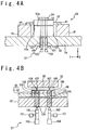
- FIG. 4A is a diagram schematically showing the configuration of the lower-side stage mechanism 24.
- the lower-side stage mechanism 24 includes a positioning stage 41, a carriage support table 42, a carriage 43 and elastic guides 44.
- the positioning stage 41 and the carriage support table 42 are supported by a bottom plate 5a of the bonding chamber 5.
- the positioning stage 41 functions as a coarse movement stage that coarsely moves the lower-side wafer 34 in a large stroke.
- the carriage support table 42 has a smooth support surface 42a at the upper end.
- the support surface 42a is perpendicular to the upper and lower direction (the Z axial direction).
- the carriage 43 holds the cartridge 32 put thereon (and the lower-side wafer 34 put on the cartridge 32).
- a function of a fine movement stage to finely move the lower-side wafer 34 in a small stroke is incorporated into the carriage 43.
- the elastic guides 44 are formed from an elastic body and are joined on the side surface of the carriage 43.
- the carriage 43 is connected to the positioning stage 41 by the elastic guides 44.
- the elastic guides 44 support the carriage 43 so that an undersurface 43a of the carriage 43 does not contact the support surface 42a of the carriage support table 42, when any load is not applied to the carriage 43.
- a gap of about 100 ⁇ m is formed between the undersurface 43a of the carriage 43 and the support surface 42a of the carriage support table 42.
- the elastic guides 44 elastically deform so that the undersurface 43a of the carriage 43 contacts the support surface 42a of the carriage support table 42.
- the positioning stage 41 drives the elastic guides 44 and the carriage 43 connected to the elastic guides 44. More specifically, the positioning stage 41 is configured to move to the axial directions of X and Y, and to rotate in an angular direction of ⁇ .
- a ball screw, a linear guide, and a moving/rotating mechanism (not shown) using a motor are incorporated into the positioning stage 41.
- the positioning stage 41 functions as the coarse movement stage.
- the carriage 43 is moved and/or rotated by the positioning stage 41, according to need.
- the cartridge 32 put on the carriage 43 (and the lower-side wafer 34 put on the cartridge 32) is moved and/or rotated.
- FIG. 4B is a diagram schematically showing the configuration of a portion of the lower-side stage mechanism 24 that is related to the alignment mechanism 27.
- the alignment mechanism 27 includes infrared illuminations 101 which generate infrared rays, lenses 102 which change the direction of the infrared rays into the vertical direction, and cameras 103.
- a transparent part 104 is formed in the carriage support table 42 and a transparent part 105 is formed (more specifically, in the stage 52 of the carriage 43 to be mentioned later) in the carriage 43.
- the transparent parts 104 and 105 are formed of transparent material to the infrared rays irradiated from the infrared illuminations 101.
- the transparent part 105 of the carriage 43 is arranged in the neighborhood of the transparent part 104 of the carriage support table 42.
- the alignment mechanism 27 detects the differences in the position and the orientation between the upper-side wafer 33 and the lower-side wafer 34, by using a transparent part 106 that is provided in the cartridge 32 put on the carriage 43, an alignment mark 107 that is provided on the upper-side wafer 33, and an alignment mark 108 that is provided on the lower-side wafer 34.
- the transparent part 106 is formed of the transparent material to the infrared rays irradiated from the infrared illuminations 101.
- the lenses 102 changes the irradiation direction of the infrared rays generated by the infrared illuminations 101 to the vertical direction such that the infrared rays are incident on the upper-side wafer 33 and the lower-side wafer 34 through the transparent parts 104, 105, and 106.
- insulation material e.g. glass
- semiconductor material e.g. silicon
- the lenses 102 lead the infrared rays reflected by the upper-side wafer 33 and the lower-side wafer 34 to the cameras 103.
- the cameras 103 pick up the reflected infrared rays which have passed through the lenses 102, to provide partial images of the upper-side wafer 33 and the lower-side wafer 34 (that is, the partial images in the neighborhood of the alignment marks 107 and 108).
- the obtained images are sent to the control unit 3 to be subject to image processing by the control unit 3.
- the differences in the position and the orientation between the upper-side wafer 33 and the lower-side wafer 34 are detected through the image processing.
- a cavity may be disposed to pass the infrared rays, instead of the transparent part 104 of the carriage support table 42.
- cavities may be disposed to pass the infrared rays, instead of the transparent parts 105 and 106 of the carriage 43 and cartridge 32.
- the transparent part 104 may be disposed in the carriage support table 42 and the cavities may be disposed in the carriage 43 and the cartridge 32 to pass the infrared rays.
- FIG. 5A is a plan view showing the configuration of the carriage 43.
- the carriage 43 includes a frame 51 and a table 52.
- the frame 51 is connected to the positioning stage 41 by the above-mentioned elastic guides 44.
- the table 52 is used as a lower-side wafer holding section that holds the cartridge 32 put thereon (and the lower-side wafer 34 put on the cartridge 32).
- the above-mentioned transparent parts 105 are formed in the table 52.
- the cavity (or the hole) may be disposed in the table 52 of the carriage 43 to pass the infrared rays, instead of the transparent part 105.
- the table 52 is surrounded by the frame 51 and is supported to the frame 51 by a plurality of hinge sections 53 to be movable. In the present example, four corners of the table 52 are connected to the frame 51 by the four hinge sections 53.
- FIG. 5B is a plan view showing the configuration of the hinge section 53.
- Each hinge section 53 has fragment members 61 and 62.
- the fragment member 61 is connected to the table 52 by a narrow section 63 and is connected to the fragment member 62 by a narrow section 64.
- the fragment member 62 is connected to the frame 51 by a narrow section 65.
- FIG. 5C is a perspective view showing the configuration of the narrow section 63.
- the narrow section 63 is configured to have a structure narrow in width, and to be curveable.
- each of the narrow sections 64 and 65 is configured to have a structure narrow in width and to be curveable.
- the hinge section 53 of such a configuration is connected with the frame 51 to allow the table 52 to move in the axial directions of X and Y, and to rotate in the angular direction of ⁇ .
- the angular direction of ⁇ is an angular direction in the XY plane.
- the carriage 43 includes three driving mechanisms 54 1 to 54 3 which drive the table 52.
- the driving mechanisms 54 1 and 54 2 drive the table 52 in the axial direction of X
- the driving mechanism 54 3 drives the table 52 in the axial direction of Y.
- the three driving mechanisms 54 1 to 54 3 are used as the fine movement mechanism to finely move the table 52.
- the driving mechanism 54 1 includes a piezo-electric device 55 1 and a connection section 56 1 .
- the piezo-electric device 55 1 has one end connected to the frame 51, and the other end connected to a connection section 56 1 .
- the piezo-electric device 55 1 moves the connection section 56 1 in the axial direction of X according to a voltage supplied to it.
- the connection section 56 1 has one end connected to the piezo-electric device 55 1 , and the other end connected to the table 52.
- the connection section 56 1 is disposed with two narrow sections 57 and can be curved there. In such a configuration, even when the table 52 is driven in the axial direction of Y by the driving mechanism 54 3 , the displacement of the table 52 in the axial direction of Y can be absorbed by curving of the narrow section 57.
- the driving mechanism 54 2 is configured like the driving mechanism 54 1 and includes a piezo-electric device 55 2 and a connection section 56 2 .
- the piezo-electric device 55 2 has one end connected to the frame 51, and the other end connected to the connection section 56 2 .
- the piezo-electric device 55 2 moves the connection section 56 2 into the axial direction of X according to a voltage supplied to it.
- the connection section 56 2 has one end connected to the piezo-electric device 55 2 , and the other end connected to the table 52.
- the connection section 56 2 is disposed with two narrow sections and can be curved there. In such a configuration, even when the table 52 is driven in the axial direction of Y by the driving mechanism 54 3 , the displacement of the table 52 in the axial direction of Y can be absorbed by curving of the narrow sections of the connection section 56 2 .
- the driving mechanism 54 3 is configured like the driving mechanisms 54 1 and 54 2 , excluding the driving direction of the table 52.
- the driving mechanism 54 3 includes a piezo-electric device 55 3 and a connection section 56 3 .
- the piezo-electric device 55 3 has one end connected to the frame 51, and the other end connected to the connection section 56 3 .
- the piezo-electric device 55 3 moves the connection section 56 3 in the axial direction of Y according to a voltage supplied to it.
- the connection section 56 3 has one end connected to the piezo-electric device 55 3 , and the other end connected to the table 52.
- the connection section 56 3 is disposed with two narrow sections and can be curved in the narrow sections.
- the carriage 43 of such a configuration functions as the fine movement stage that can move the table 52 in the axial directions of X and Y and rotate it in the angular direction of ⁇ .
- the voltages are supplied to the piezo-electric devices 55 1 and 55 2 of the driving mechanisms 54 1 and 54 2 such that the piezo-electric devices 55 1 and 55 2 are operated by a same quantity.
- the voltages supplied to the piezo-electric devices 55 1 and 55 2 it is possible to move the table 52 to a desired position in the axial direction of X.
- the voltages are supplied to the piezo-electric devices 55 1 and 55 2 of the driving mechanisms 54 1 and 54 2 such that the piezo-electric devices 55 1 and 55 2 are operated by an identical quantity.
- the voltages are supplied to the piezo-electric devices 55 1 and 55 2 of the driving mechanisms 54 1 and 54 2 such that the piezo-electric devices 55 1 and 55 2 are operated by different quantities.
- the carriage 43 of such a configuration can move or rotate the table 52 in a high precision because the piezo-electric devices 55 1 , 55 2 and 55 3 are used for the movement or rotation of the table 52.
- the carriage 43 can carry out the positioning of the lower-side wafer 34 which is held by the cartridge 32 put on the table 52 in a high precision.
- the positioning stage 41 operates as a coarse movement stage mechanism and the carriage 43 operates as a fine movement stage mechanism. That is, the positioning stage 41 operates as a stage mechanism in which the stroke is large but the precision is low, compared with the carriage 43.
- the carriage 43 operates as a stage mechanism in which the stroke is small but the precision is high, compared with the positioning stage 41.
- the lower-side wafer 34 when the lower-side wafer 34 should be moved or rotated in at least one of the directions of X, Y and ⁇ in a small displacement, the lower-side wafer 34 is moved or rotated by the carriage 43. Through such an operation, the lower-side stage mechanism 24 can realize a sufficiently large stroke and the precise positioning of the wafer.
- the undersurface 43a of the carriage 43 contacts the support surface 42a of the carriage support table 42 so that the load is mainly applied to the carriage support table 42. Therefore, the load applied to the positioning stage 41 functioning as the coarse movement stage is reduced. According to such a configuration, the withstand load property of the lower-side stage mechanism 24 can be increased.
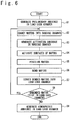
- FIG. 6 is a flow chart showing the room-temperature bonding method of the present example. This room-temperature bonding method is performed by using the above-mentioned room-temperature bonding apparatus 1.
- the user sets the cartridge 31 having the upper-side wafer 33 thereon on the cartridge stand 12 of the load lock chamber 4 and the cartridge 32 having the lower-side wafer 34 thereon on the cartridge stand 13.
- the plurality of cartridges 31 may be set on the cartridge stand 12, and the cartridges 32 of the same number may be set on the cartridge stand 13.
- the preliminary ambience is a vacuum ambience of an extent that it is permitted that the load lock chamber 4 and the bonding chamber 5 are communicated through the conveyance passage 6 by opening the gate valve 7.
- Step S2 one sheet of upper-side wafer 33 and one sheet of lower-side wafer 34 are conveyed to the bonding chamber 5 (Step S2). Specifically, the gate valve 7 is opened, and the cartridge 31 having the upper-side wafer 33 is conveyed from the cartridge stand 12 of the load lock chamber 4 onto the table 52 of the carriage 43 of the bonding chamber 5 by the conveyance robot 14.
- the electrostatic chuck 25 is dropped down by the pressure welding mechanism 26. The dropping operation of the electrostatic chuck 25 is stopped at the timing that the upper-side wafer 33 on the cartridge 31 is in contact with the electrostatic chuck 25. Subsequently, the upper-side wafer 33 is held by the electrostatic chuck 25.
- the electrostatic chuck 25 is raised to a predetermined standby position by the pressure welding mechanism 26.
- the cartridge 31 is conveyed from the carriage 43 to the cartridge stand 12 by the conveyance robot 14.
- the cartridge 32 having the lower-side wafer 34 is conveyed from the cartridge stand 13 onto the table 52 of the carriage 43 by the conveyance robot 14.
- the gate valve 7 is closed.
- Step S3 an activation ambience is generated inside the bonding chamber 5 (Step S3). More specifically, the degree of vacuum inside the bonding chamber 5 is controlled to about 10 -5 to 10 -6 Pa by the vacuum exhaust unit 21.
- Step S4 the surface of the upper-side wafer 33 and the surface of the lower-side wafer 34 are activated. Specifically, an ion beam 22a is irradiated from the ion gun 22 to the surface of the upper-side wafer 33 and the surface of the lower-side wafer 34. Thus, the surface of the upper-side wafer 33 and the surface of the lower-side wafer 34 are etched. During the irradiation of the ion beam 22a, the degree of vacuum inside the bonding chamber 5 becomes about 10 -2 to 10 -3 Pa.
- Step S5 the positioning of the upper-side wafer 33 and the lower-side wafer 34 is carried out by the upper-side stage mechanism 23 and the lower-side stage mechanism 24 (Step S5).
- the electrostatic chuck 25 is dropped down by the pressure welding mechanism 26 of the upper-side stage mechanism 23, such that the electrostatic chuck 25 is arranged at a predetermined alignment position.
- the upper-side wafer 33 and the lower-side wafer 34 are away from each other by a predetermined alignment distance.
- the lower-side wafer 34 is moved and/or rotated by the lower-side stage mechanism 24 and the alignment with the upper-side wafer 33 is carried out in a horizontal plane.
- the alignment between the upper-side wafer 33 and the lower-side wafer 34 is carried out according to the following procedure.
- an positional deviation quantity between the alignment marks 107 and 108 of the upper-side wafer 33 and the lower-side wafer 34 positional deviation quantities in the axial direction of X and the axial direction of Y
- an orientational deviation quantity a deviation in the angular direction of ⁇
- the positional deviation quantities are calculated as a positional difference between the alignment marks 107 and 108
- the orientational deviation quantity is calculated as an angular difference between the alignment marks 107 and 108.
- the lower-side stage mechanism 24 moves or rotates the lower-side wafer 34 to cancel the at least one deviation quantity.
- each of the coarse movement of the lower-side wafer 34 by the positioning stage 41 and the fine movement of the lower-side wafer 34 by the driving mechanisms 54 1 to 54 3 of the carriage 43 is selectively carried out according to the positional deviation quantities and the orientational deviation quantity between the alignment marks.
- the carriage 43 is driven by the positioning stage 41 so as to move or rotate the carriage 43.
- the table 52 is driven by the driving mechanisms 54 1 to 54 3 of the carriage 43.
- the lower-side wafer 34 put on the cartridge 32 which has been held on the table 52 is driven to cancel the positional deviation quantities and the orientational deviation quantity between the alignment markers.
- a procedure of detecting the positions of the alignment marks and an angle between the alignment marks is repeatedly carried out until both of the positional deviation quantities and the orientational deviation quantity between the alignment marks fall within the reference range.
- Step S6 the upper-side wafer 33 and the lower-side wafer 34 are brought into contact with each other and are bonded to each other.
- the electrostatic chuck 25 is dropped down by the pressure welding mechanism 26 such that the surface of the upper-side wafer 33 is brought into contact with the surface of the lower-side wafer 34.
- the dropping operation of the electrostatic chuck 25 is stopped at the timing that the load applied to the electrostatic chuck 25 reaches a predetermined bonding load. That is, the bonding load is applied to the upper-side wafer 33 and the lower-side wafer 34.
- the upper-side wafer 33 and the lower-side wafer 34 are bonded by applying the bonding load, to form one sheet of the bonded wafer.
- the application of the bonding load to the bonded wafer continues for a predetermined bonding time.
- the load is applied to the table 52 of the carriage 43 in the vertically lower direction.
- the elastic guides 44 are deformed elastically, such that the undersurface 43a of the carriage 43 contacts the support surface 42a of the carriage support table 42.
- the load applied to the table 52 is mainly applied to the carriage support table 42, while the load applying on the positioning stage 41 is reduced. This means that the withstand load property of the lower-side stage mechanism 24 can be increased.
- Step S7 the bonded wafer is conveyed to the load lock chamber 4 (Step S7). Specifically, after the bonded wafer is separated from the electrostatic chuck 25, the electrostatic chuck 25 is raised by the pressure bonding mechanism 26. At this time, the bonded wafer is left in the state that it is put on the cartridge 32. After that, when the gate valve 7 is opened, the cartridge 32 on which the bonded wafer has been put on is conveyed from the table 52 of the carriage 43 to the load lock chamber 4 by the conveyance robot 14 and then is returned to the cartridge stand 13.
- step S8 YES
- the operation of step S2 to step S7 is carried out once again.
- Step S9 the vacuum exhaust unit 11 of the load lock chamber 4 is controlled to generate an atmospheric ambience inside the load lock chamber 4.
- the user can open the lid of the load lock chamber 4 and take out the cartridge 32 on which the bonded wafer has been put and the cartridge 31 having no wafer from the cartridge stands 12 and 13.
- the procedure of the bonding of the upper-side wafer 33 and the lower-side wafer 34 completes.
- the above-mentioned steps S1 to S9 are realized by executing a computer program 36a by the control unit 3.
- the positioning stage 41 of the lower-side stage mechanism 24 operates as the coarse movement stage mechanism in which the lower-side wafer 34 is coarsely moved, and the carriage 43 operates as the fine movement stage mechanism in which the lower-side wafer 34 is finely moved.
- the lower-side stage mechanism 24 can realize a sufficiently large stroke and precise positioning of the wafer.
- the elastic guides 44 which support the carriage 43 are deformed elastically so that the undersurface 43a of the carriage 43 contacts the support surface 42a of the carriage support table 42.
- the load is mainly applied to the carriage support table 42. Therefore, the load applied to the positioning stage 41 which functions as the coarse movement stage mechanism is reduced. According to such a configuration, the withstand load property of the lower-side stage mechanism 24 can be increased.
- FIG. 7 is a sectional view schematically showing the configuration of the room-temperature bonding apparatus 1 according to an embodiment of the present invention, especially, the configuration of a lower-side stage mechanism 24A.
- the configuration of the room-temperature bonding apparatus 1 of the embodiment is almost same as that of the room-temperature bonding apparatus 1 of the first example.
- the configuration of the lower-side stage mechanism 24A is different from the configuration of the lower-side stage mechanism 24 of the first example.
- the alignment mechanism 27 may be incorporated into the lower-side stage 24A, like the first example, but is not shown in FIG. 7 .
- a carriage 43A of the lower-side stage mechanism 24A includes a carriage plate 46 and a fine movement stage 47 mounted on the carriage plate 46.
- the carriage plate 46 is connected to the positioning stage 41 by the elastic guides 44.
- the positioning stage 41 functions as the coarse movement stage having a large stroke.
- the carriage plate 46 has a smooth upper surface and a smooth undersurface.
- the elastic guides 44 support the carriage plate 46 so as for the lower surface of the carriage plate 46 not to contact the support surface 42a of the carriage support table 42, when a load is not applied to the carriage 43A. At this time, a gap of about 100 ⁇ m is provided between the undersurface of the carriage plate 46 and the support surface 42a of the carriage support table 42.
- the elastic guides 44 elastically deform so that the undersurface of the carriage plate 46 contacts the support surface 42a of the carriage support table 42.
- the fine movement stage 47 has the same configuration as the carriage 43 shown in FIG. 5A to FIG. 5C (in this case, the frame 51 is not directly connected to the elastic guides 44).
- the fine movement stage 47 includes the frame 51 and the table 52.
- the table 52 is used as a lower-side wafer holding section having the cartridge 32 put thereon (and the lower-side wafer 34 put on the cartridge 32).
- the table 52 is surrounded by the frame 51 and is movably supported to the frame 51 by the four hinge sections 53.
- the fine movement stage 47 includes three driving mechanisms 54 1 to 54 3 which drive the table 52.
- the driving mechanisms 54 1 and 54 2 drive the table 52 in the axial direction of X and the driving mechanism 54 3 drives the table 52 in the axial direction of Y.
- the undersurfaces of the frame 51 and table 52 of the fine movement stage 47 are bonded to the surface of the carriage plate 46.
- the configuration of the lower-side stage mechanism 24A of the present embodiment can satisfy the requests of the precise positioning of the wafer and the large withstand load property, while providing a sufficiently large stroke, like the first example.
- the positioning stage 41 of the lower-side stage mechanism 24A operates as the coarse movement stage mechanism coarsely moving the lower-side wafer 34 while the fine movement stage 47 of the carriage 43A is used to finely move the lower-side wafer 34.
- the lower-side stage mechanism 24 can realize the sufficiently large stroke and the precise positioning of the wafer.
- the elastic guides 44 supporting the carriage plate 46 deform elastically so that the undersurface of the carriage plate 46 contacts the support surface 42a of the carriage support table 42.
- the load is mainly applied to the carriage support table 42. Therefore, the load applied to the positioning stage 41 functioning as the coarse movement stage mechanism is reduced and it is possible to increase the withstand load property of the lower-side stage mechanism 24.
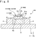
- FIG. 8 is a sectional view schematically showing the configuration of the lower-side stage mechanism 24A in a modification example of the room-temperature bonding apparatus 1 according to the embodiment.
- the table 52 of the fine movement stage 47 is supported by the hinge sections 53 to be movable in an upper and lower direction (the axial direction of Z).
- the table 52 is supported such that there is a gap between the undersurface of the table 52 and the upper surface of the carriage plate 46.
- the configuration having the gap between the undersurface of the table 52 and the upper surface of the carriage plate 46 is effective in that it is possible to make the operation of the fine movement stage 47 smooth and to prevent a precision drop, because the table 52 never grazes the carriage plate 46 when the table 52 moves. Also, it is possible to restrain the generation of particles when the table 52 grazes the carriage plate 46.
- the hinge sections 53 supporting the table 52 deform elastically so that the undersurface 52a of the table 52 is brought into contact with the upper surface 46a of the carriage plate 46.
- the carriage plate 46 is also pushed in the vertically lower direction so that the undersurface of the carriage plate 46 is brought into contact with the support surface 42a of the carriage support table 42.
- the load is mainly applied to the carriage support table 42.
- the load acting on the hinge sections 53 of the fine movement stage 47 is reduced so that the damaging of the hinge sections 53 can be prevented.
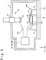
- FIG. 9 is a sectional view schematically showing the configuration of the room-temperature bonding apparatus 1 according to a second example serving to explain aspects of the present invention, especially, the configuration of the lower-side stage mechanism 24B.
- the configuration of the room-temperature bonding apparatus 1 of the second example is similar to that of the room-temperature bonding apparatus 1 of the first example and the embodiment.
- the configuration of the lower-side stage mechanism 24B is different from the configurations of the lower-side stage mechanism 24 of the first example and the lower-side stage mechanism 24A of the embodiment.
- the alignment mechanism 27 may be incorporated into the lower-side stage 24B, like the first example, but is not shown in FIG. 9 .
- the lower-side stage mechanism 24B includes the positioning stage 41, the carriage support table 42, a fine movement stage 71, a carriage 72 and an elastic guide 73.
- the positioning stage 41 functions as the coarse movement stage having a large stroke.
- the carriage support table 42 has the smooth support surface 42a as the upper end.
- the support surface 42a is perpendicular to the upper and lower direction (the axial direction of Z).
- the fine movement stage 71 has the configuration similar to the carriage 43 (fine movement stage 47) shown in FIG. 5A to FIG. 5C .
- the fine movement stage 71 includes the frame 51 and the table 52.
- the table 52 is used as the wafer holding section that holds the cartridge 32 put thereon (and the lower-side wafer 34 put on the cartridge 32).
- the table 52 is arranged to be surrounded by the frame 51, and is supported to the frame 51 by four hinge sections 53.
- the fine movement stage 47 includes three driving mechanisms 54 1 to 54 3 for driving the table 52.
- the driving mechanisms 54 1 and 54 2 drive the table 52 to the axial direction of X, and the driving mechanism 54 3 drives the table 52 to the axial direction of Y.
- the frame 51 of the fine movement stage 47 is joined to the surface of the positioning stage 41.
- the carriage 72 functions as the lower-side wafer holding section that holds the cartridge 32 put thereon (and the lower-side wafer 34 put on the cartridge 32).
- the elastic guide 73 is formed of elastic body and is joined to the side surface of the carriage 72.
- the carriage 72 is connected to the table 52 of the fine movement stage 71 by the elastic guide 73.
- the elastic guide 73 supports the carriage 72 so as for the lower surface 72a of the carriage 72 not to contact the support surface 42a of the carriage support table 42 when any load is not applied to the carriage 72.
- a gap of about 100 ⁇ m is provided between an undersurface 72a of the carriage 72 and the support surface 42a of the carriage support table 42.
- the elastic guide 73 deforms elastically for the undersurface 72a of the carriage 72 to contact the support surface 42a of the carriage support table 42.
- the configuration of the lower-side stage mechanism 24B in the present example can satisfy the requests of the precise positioning of the wafer and the large withstand load property while providing the sufficiently large stroke, like the first example.
- the positioning stage 41 of the lower-side stage mechanism 24B functions as the coarse movement stage mechanism which coarsely moves the lower-side wafer 34. That is, the positioning stage 41 moves and/or rotates the fine movement stage, by driving the whole fine movement stage 71, when the coarse movement of the lower-side wafer 34 should be carried out. Because the carriage 72 that holds the lower-side wafer 34 is connected to the table 52 of the fine movement stage 71 by the elastic guide 73, the lower-side wafer 34 can be moved by moving the whole fine movement stage 71.
- the fine movement stage 71 is used to move the lower-side wafer 34.
- the driving mechanisms 54 1 to 54 3 of the fine movement stage 71 move and/or rotate the table 52. Because the carriage 72 that holds the lower-side wafer 34 is connected to the table 52 by the elastic guide 73, the lower-side wafer 34 can be moved by moving the table 52. By such an operation, the lower-side stage mechanism 24B can realize a sufficiently large stroke and the precise positioning of the wafer.
- the elastic guide 73 supporting the carriage 72 deforms elastically such that the undersurface 72a of the carriage 72 is brought into contact with the support surface 42a of the carriage support table 42.
- the load is mainly applied to the carriage support table 42.
- the effect is obtained that the load applied to the fine movement stage 71 can be reduced, in addition to the reducing of the load applied to the positioning stage 41 that functions as the coarse movement stage mechanism. This contributes the increase of the withstand load property of the lower-side stage mechanism 24B.
- FIG. 11 is a side view schematically showing the configuration of an upper-side stage mechanism 23A having such a configuration.
- the upper-side stage mechanism 23A has an elevation rod 81 that moves in the upper and lower direction.
- the electrostatic chuck 83 is installed at the bottom end of the elevation rod 81 to hold the upper-side wafer 33 through the angle adjustment mechanism 82.
- the angle adjustment mechanism 82 includes a spherical seat 84 connected to the bottom end of the elevation rod 81, a fixation flange 85 and a spherical flange 86 attached to the electrostatic chuck 83.
- the spherical flange 86 has a supporting section and a flange section. The supporting section is joined to the electrostatic chuck 83.
- the flange section is formed as a sphere having a point 86a as a center.
- the spherical seat 84 has a spherical seat surface to tightly fit to the flange section of the spherical flange 86.
- the fixation flange 85 is joined to the spherical seat 84 with a fastening member such as a bolt, and supports the flange section of the spherical flange 86 to make the flange section tightly fit to the spherical seat surface of the spherical seat 84.
- the flange section of spherical flange 86 is slidably connected to the spherical seat surface of the spherical seat 84 with the fixation flange 85.
- FIG. 12 is a perspective view showing the configuration of the fixation flange 85.
- the fixation flange 85 includes divisional rings 87a and 87b.
- the divisional rings 87a and 87b have the shapes of parts of a ring, respectively.
- the divisional rings 87a and 87b are respectively connected to the spherical seat 84 by the fastening member such as a bolt.
- the divisional rings 87a and 87b are arranged to contact the flange section of the spherical flange 86 in its inner side to support the flange section therebetween.
- the upper-side wafer 33 and the lower-side wafer 34 can be bonded while maintaining a parallelism between the upper-side wafer 33 and the lower-side wafer 34. This is effective to apply a large bonding load uniformly to the upper-side wafer 33 and the lower-side wafer 34.
Landscapes
- Engineering & Computer Science (AREA)
- Physics & Mathematics (AREA)
- Condensed Matter Physics & Semiconductors (AREA)
- General Physics & Mathematics (AREA)
- Manufacturing & Machinery (AREA)
- Computer Hardware Design (AREA)
- Microelectronics & Electronic Packaging (AREA)
- Power Engineering (AREA)
- Container, Conveyance, Adherence, Positioning, Of Wafer (AREA)
- Pressure Welding/Diffusion-Bonding (AREA)
Claims (4)
- Dispositif (1) de liaison à température ambiante, comprenant :une chambre (5) de liaison ;un mécanisme (23) d'étage du côté supérieur configuré pour supporter une pastille (33) du côté supérieur dans la chambre (5) de liaison pour qu'elle soit mobile dans un sens vers le haut et vers le bas ;un mécanisme (24) d'étage de côté inférieur configuré pour supporter une pastille (34) de côté inférieur dans la chambre (5) de liaison pour qu'elle soit mobile dans un plan horizontal ;un mécanisme (27) d'alignement incorporé au mécanisme (24) d'étage du côté inférieur et configuré pour prendre une image d'un repère (107) d'alignement formé sur une surface de la pastille (33) de côté supérieur maintenue par le mécanisme (23) d'étage du côté supérieur et une image d'un repère (108) d'alignement formé sur une surface de la pastille (34) de côté inférieur mise sur le mécanisme (24) d'étage du côté inférieur etune unité (3) de commande configurée pour détecter une différence de position et d'orientation entre la pastille (33) de côté supérieur et la pastille (34) de côté inférieur par un traitement des images des repères (107, 108) d'alignement pris par le mécanisme (27) d'alignement,dans lequel le mécanisme (24) d'étage du côté inférieur comprend :un chariot (43; 43A) ayant une partie de maintien de la pastille de côté inférieur configuré pour maintenir la pastille (34) de côté inférieur ;une glissière (44; 73) élastique reliée au chariot (43; 43A) pour supporter le chariot (43; 43A) ;un étage (41) de mise en position configuré pour déplacer grossièrement la partie de maintien de la pastille de côté inférieur sous la commande de l'unité (3) de commande en fonction de la différence détectée de position et d'orientation ;
etun socle (42) de support de chariot,dans lequel la glissière (44; 73) élastique supporte le chariot (43; 43A), de manière à ce que le chariot (43; 43A) n'entre pas en contact avec le socle (42) de support du chariot, lorsqu'une charge n'est pas appliquée au chariot (43; 43A) à partir du mécanisme (23) d'étage du côté supérieur, et est configurée pour se déformer élastiquement, de manière à ce que le chariot (43; 43A) entre en contact avec le socle (42) de support du chariot, lorsque la pastille (33) de côté supérieur entre en contact avec la pastille (34) de côté inférieur et lorsqu'une charge est appliquée au chariot (43; 43A) dans un sens vers le haut et vers le bas par le mécanisme (23) d'étage du côté supérieur,caractérisé en ce quele mécanisme (24) d'étage du côté inférieur comprend un mécanisme de déplacement fin configuré pour déplacer finement la partie de maintien de la pastille de côté inférieur sous la commande de l'unité (3) de commande en fonction de la différence détectée de position et d'orientation etune partie (105) transparente est formée dans le mécanisme de déplacement fin, de manière à ce que le mécanisme (27) d'alignement puisse prendre l'image du repère (107) d'alignement formé sur la surface de la pastille (33) de côté supérieur,dans lequel l'étage (41) de mise en position est configurée pour entraîner la glissière (44; 73) élastique, afin qu'elle déplace grossièrement la partie de maintien de la pastille de côté inférieur,dans lequel le mécanisme de mouvement fin est incorporé au chariot (43; 43A),dans lequel le chariot (43; 43A) comprend une plaque (46) de chariot, à laquelle la glissière (44) élastique est jointe,dans lequel la partie de maintien de la pastille de côté inférieur est disposée au-dessus de la plaque (46) du chariot,dans lequel le mécanisme de déplacement fin comprend :un bâti (51) disposé sur la plaque (46) du chariot etun mécanisme (54) d'entraînement relié au bâti (51) pour entraîner la partie de maintien de la pastille de côté inférieur etdans lequel, lorsque le mécanisme (23) d'étage du côté supérieur met la pastille (33) de côté supérieur en contact avec la pastille (34) de côté inférieur et applique la charge au chariot (43A) dans la direction vers le haut et vers le bas, la glissière (44) élastique est configurée pour se déformer élastiquement, de manière à ce que la plaque (46) du chariot entre en contact avec le socle (42) de support de chariot. - Dispositif (1) de liaison à la température ambiante suivant la revendication 1, dans lequel un mécanisme de support est disposé dans le bâti (51) pour supporter, de manière mobile, la partie de maintien de la pastille de côté inférieur dans le sens vers le haut et vers le bas et
dans lequel le mécanisme de support supporte la partie de maintien de la pastille de côté inférieur, de manière à ce que la partie de maintien de la pastille de côté inférieur n'entre pas en contact avec la plaque (46) du chariot, lorsqu'une charge n'est pas appliquée à la partie de maintien de la pastille de côté inférieur à partir du mécanisme (23) d'étage du côté supérieur, et est configuré pour se déformer élastiquement, de manière à ce que la partie de maintien de la pastille de côté inférieur entre en contact avec la plaque (46) du chariot, lorsque le mécanisme (23) d'étage du côté supérieur met la pastille (33) de côté supérieur en contact avec la pastille (34) de côté inférieur et applique une charge à la partie de maintien de la pastille de côté inférieur dans la direction vers le haut et vers le bas. - Dispositif (1) de liaison à la température ambiante suivant la revendication 1 ou 2, dans lequel le mécanisme (23A) d'étage de côté supérieur comprend :une partie de maintien de la pastille de côté supérieur configurée pour maintenir la pastille (33) de côté supérieur etun mécanisme (82) de réglage d'angle configuré pour régler une orientation de la partie de maintien de la pastille de côté supérieur.
- Dispositif (1) de liaison à la température ambiante suivant la revendication 3, dans lequel le mécanisme (23) d'étage de côté supérieur comprend, en outre, une barre (81) d'élévation configurée pour se déplacer dans la direction vers le haut et vers le bas et
le mécanisme (82) de réglage d'angle comprend :une bride (86) sphérique fixée à la partie de maintien de la pastille de côté supérieur ;un siège (84) sphérique fixé à la barre (80) d'élévation etune bride (85) de fixation fixée au siège (84) sphérique, et configurée pour relier la bride (86) sphérique au siège (84) sphérique en y supportant la bride (85) sphérique.
Applications Claiming Priority (2)
| Application Number | Priority Date | Filing Date | Title |
|---|---|---|---|
| JP2014006869A JP6125443B2 (ja) | 2014-01-17 | 2014-01-17 | 常温接合装置 |
| PCT/JP2014/084495 WO2015107855A1 (fr) | 2014-01-17 | 2014-12-26 | Dispositif de liaison à température normale |
Publications (3)
| Publication Number | Publication Date |
|---|---|
| EP3062333A1 EP3062333A1 (fr) | 2016-08-31 |
| EP3062333A4 EP3062333A4 (fr) | 2016-12-28 |
| EP3062333B1 true EP3062333B1 (fr) | 2019-06-12 |
Family
ID=53542755
Family Applications (1)
| Application Number | Title | Priority Date | Filing Date |
|---|---|---|---|
| EP14878983.7A Active EP3062333B1 (fr) | 2014-01-17 | 2014-12-26 | Dispositif de liaison à température normale |
Country Status (4)
| Country | Link |
|---|---|
| US (1) | US20170162428A1 (fr) |
| EP (1) | EP3062333B1 (fr) |
| JP (1) | JP6125443B2 (fr) |
| WO (1) | WO2015107855A1 (fr) |
Families Citing this family (4)
| Publication number | Priority date | Publication date | Assignee | Title |
|---|---|---|---|---|
| WO2014105989A1 (fr) * | 2012-12-31 | 2014-07-03 | Flir Systems, Inc. | Encapsulation sur tranche d'ensembles boîtiers sous vide de microbolomètre |
| JP6165127B2 (ja) * | 2014-12-22 | 2017-07-19 | 三菱重工工作機械株式会社 | 半導体装置及び半導体装置の製造方法 |
| JP6731805B2 (ja) * | 2016-07-12 | 2020-07-29 | 東京エレクトロン株式会社 | 接合システム |
| US10663661B1 (en) * | 2018-01-26 | 2020-05-26 | Partow Technologies, Llc. | Apparatus for bonding wafers and an optically-transparent thin film made from the same |
Citations (1)
| Publication number | Priority date | Publication date | Assignee | Title |
|---|---|---|---|---|
| US20030179353A1 (en) * | 2000-08-25 | 2003-09-25 | Akira Yamauchi | Alignment device |
Family Cites Families (10)
| Publication number | Priority date | Publication date | Assignee | Title |
|---|---|---|---|---|
| JP2984441B2 (ja) * | 1991-12-06 | 1999-11-29 | 光正 小柳 | 三次元lsi積層装置 |
| JP4822577B2 (ja) | 2000-08-18 | 2011-11-24 | 東レエンジニアリング株式会社 | 実装方法および装置 |
| TW588926U (en) * | 2003-06-13 | 2004-05-21 | Hon Hai Prec Ind Co Ltd | Heat sink clip |
| JP4459687B2 (ja) | 2004-03-31 | 2010-04-28 | 地方独立行政法人山口県産業技術センター | 砥石とその製造方法 |
| JP2005288673A (ja) * | 2004-04-06 | 2005-10-20 | Mitsubishi Heavy Ind Ltd | 微小構造体の製造装置 |
| JP4669766B2 (ja) | 2005-09-29 | 2011-04-13 | ボンドテック株式会社 | 位置決め方法、この方法を用いた加圧方法および位置決め装置、この装置を備える加圧装置 |
| JP3970304B1 (ja) | 2006-03-27 | 2007-09-05 | 三菱重工業株式会社 | 常温接合装置 |
| FR2924274B1 (fr) * | 2007-11-22 | 2012-11-30 | Saint Gobain | Substrat porteur d'une electrode, dispositif electroluminescent organique l'incorporant, et sa fabrication |
| JP4209457B1 (ja) * | 2008-02-29 | 2009-01-14 | 三菱重工業株式会社 | 常温接合装置 |
| JP5565792B2 (ja) * | 2009-11-02 | 2014-08-06 | ボンドテック株式会社 | アライメント装置 |
-
2014
- 2014-01-17 JP JP2014006869A patent/JP6125443B2/ja active Active
- 2014-12-26 US US15/039,545 patent/US20170162428A1/en not_active Abandoned
- 2014-12-26 WO PCT/JP2014/084495 patent/WO2015107855A1/fr active Application Filing
- 2014-12-26 EP EP14878983.7A patent/EP3062333B1/fr active Active
Patent Citations (1)
| Publication number | Priority date | Publication date | Assignee | Title |
|---|---|---|---|---|
| US20030179353A1 (en) * | 2000-08-25 | 2003-09-25 | Akira Yamauchi | Alignment device |
Also Published As
| Publication number | Publication date |
|---|---|
| JP2015135903A (ja) | 2015-07-27 |
| EP3062333A1 (fr) | 2016-08-31 |
| EP3062333A4 (fr) | 2016-12-28 |
| WO2015107855A1 (fr) | 2015-07-23 |
| US20170162428A1 (en) | 2017-06-08 |
| JP6125443B2 (ja) | 2017-05-10 |
Similar Documents
| Publication | Publication Date | Title |
|---|---|---|
| US6214692B1 (en) | Method and apparatus for the aligned joining of disk-shaped semiconductor substrates | |
| TWI825958B (zh) | 用於對準基板之方法及裝置 | |
| JP4887913B2 (ja) | 基板処理装置、基板処理方法及び記憶媒体 | |
| US9379082B2 (en) | Pressure application apparatus and pressure application method | |
| KR102191735B1 (ko) | 기판 위치 맞춤 장치, 기판 접합 장치, 기판 위치 맞춤 방법, 적층 반도체 장치의 제조 방법, 및 기판 접합 방법 | |
| KR102429940B1 (ko) | 적층 기판 제조 방법, 적층 기판 제조 장치, 적층 기판 제조 시스템, 및 기판 처리 장치 | |
| EP3062333B1 (fr) | Dispositif de liaison à température normale | |
| CN110383446B (zh) | 用于接合至少三个衬底的方法 | |
| US20210313211A1 (en) | Component mounting system and component mounting method | |
| CN110718495A (zh) | 接合装置和接合方法 | |
| US6825915B2 (en) | Alignment device | |
| JP7542885B2 (ja) | 接合方法および接合装置 | |
| WO2016024364A1 (fr) | Dispositif de montage et procédé de mesure | |
| JP7290988B2 (ja) | アライメント装置、成膜装置、アライメント方法、成膜方法および電子デバイスの製造方法 | |
| KR20190029697A (ko) | 본딩 정렬을 위한 디바이스 및 방법 | |
| JP5454310B2 (ja) | 基板貼り合わせ装置および基板貼り合わせ方法 | |
| CN112626475A (zh) | 成膜装置及成膜方法、信息获取装置、对准方法和电子设备的制造装置及制造方法 | |
| US20160001543A1 (en) | Bonding device, bonding system, and bonding method | |
| CN112813381B (zh) | 成膜装置 | |
| JP6275632B2 (ja) | 常温接合装置及び常温接合方法 | |
| KR101394312B1 (ko) | 웨이퍼 정렬장치 | |
| JPH06510639A (ja) | ボンディングによって結合される基板をスタックする方法及び装置 | |
| US20130230371A1 (en) | Processing apparatus and device manufacturing method | |
| JP4681241B2 (ja) | アライメント方法、この方法を用いた接合方法、接合装置 | |
| US20160064266A1 (en) | Processing apparatus, processing method, and device manufacturing method |
Legal Events
| Date | Code | Title | Description |
|---|---|---|---|
| PUAI | Public reference made under article 153(3) epc to a published international application that has entered the european phase |
Free format text: ORIGINAL CODE: 0009012 |
|
| 17P | Request for examination filed |
Effective date: 20160523 |
|
| AK | Designated contracting states |
Kind code of ref document: A1 Designated state(s): AL AT BE BG CH CY CZ DE DK EE ES FI FR GB GR HR HU IE IS IT LI LT LU LV MC MK MT NL NO PL PT RO RS SE SI SK SM TR |
|
| AX | Request for extension of the european patent |
Extension state: BA ME |
|
| A4 | Supplementary search report drawn up and despatched |
Effective date: 20161124 |
|
| RIC1 | Information provided on ipc code assigned before grant |
Ipc: H01L 21/02 20060101AFI20161118BHEP Ipc: B23K 20/00 20060101ALI20161118BHEP Ipc: H01L 21/683 20060101ALI20161118BHEP Ipc: H01L 21/68 20060101ALI20161118BHEP |
|
| DAX | Request for extension of the european patent (deleted) | ||
| STAA | Information on the status of an ep patent application or granted ep patent |
Free format text: STATUS: EXAMINATION IS IN PROGRESS |
|
| 17Q | First examination report despatched |
Effective date: 20171023 |
|
| REG | Reference to a national code |
Ref country code: DE Ref legal event code: R079 Ref document number: 602014048430 Country of ref document: DE Free format text: PREVIOUS MAIN CLASS: H01L0021020000 Ipc: H01L0021670000 |
|
| GRAP | Despatch of communication of intention to grant a patent |
Free format text: ORIGINAL CODE: EPIDOSNIGR1 |
|
| STAA | Information on the status of an ep patent application or granted ep patent |
Free format text: STATUS: GRANT OF PATENT IS INTENDED |
|
| RIC1 | Information provided on ipc code assigned before grant |
Ipc: H01L 21/68 20060101ALI20181115BHEP Ipc: H01L 21/687 20060101ALI20181115BHEP Ipc: H01L 21/67 20060101AFI20181115BHEP |
|
| INTG | Intention to grant announced |
Effective date: 20181210 |
|
| GRAS | Grant fee paid |
Free format text: ORIGINAL CODE: EPIDOSNIGR3 |
|
| GRAA | (expected) grant |
Free format text: ORIGINAL CODE: 0009210 |
|
| STAA | Information on the status of an ep patent application or granted ep patent |
Free format text: STATUS: THE PATENT HAS BEEN GRANTED |
|
| AK | Designated contracting states |
Kind code of ref document: B1 Designated state(s): AL AT BE BG CH CY CZ DE DK EE ES FI FR GB GR HR HU IE IS IT LI LT LU LV MC MK MT NL NO PL PT RO RS SE SI SK SM TR |
|
| REG | Reference to a national code |
Ref country code: GB Ref legal event code: FG4D |
|
| REG | Reference to a national code |
Ref country code: CH Ref legal event code: EP |
|
| REG | Reference to a national code |
Ref country code: AT Ref legal event code: REF Ref document number: 1143680 Country of ref document: AT Kind code of ref document: T Effective date: 20190615 |
|
| REG | Reference to a national code |
Ref country code: DE Ref legal event code: R096 Ref document number: 602014048430 Country of ref document: DE |
|
| REG | Reference to a national code |
Ref country code: IE Ref legal event code: FG4D |
|
| REG | Reference to a national code |
Ref country code: NL Ref legal event code: MP Effective date: 20190612 |
|
| REG | Reference to a national code |
Ref country code: LT Ref legal event code: MG4D |
|
| PG25 | Lapsed in a contracting state [announced via postgrant information from national office to epo] |
Ref country code: AL Free format text: LAPSE BECAUSE OF FAILURE TO SUBMIT A TRANSLATION OF THE DESCRIPTION OR TO PAY THE FEE WITHIN THE PRESCRIBED TIME-LIMIT Effective date: 20190612 Ref country code: FI Free format text: LAPSE BECAUSE OF FAILURE TO SUBMIT A TRANSLATION OF THE DESCRIPTION OR TO PAY THE FEE WITHIN THE PRESCRIBED TIME-LIMIT Effective date: 20190612 Ref country code: LT Free format text: LAPSE BECAUSE OF FAILURE TO SUBMIT A TRANSLATION OF THE DESCRIPTION OR TO PAY THE FEE WITHIN THE PRESCRIBED TIME-LIMIT Effective date: 20190612 Ref country code: HR Free format text: LAPSE BECAUSE OF FAILURE TO SUBMIT A TRANSLATION OF THE DESCRIPTION OR TO PAY THE FEE WITHIN THE PRESCRIBED TIME-LIMIT Effective date: 20190612 Ref country code: NO Free format text: LAPSE BECAUSE OF FAILURE TO SUBMIT A TRANSLATION OF THE DESCRIPTION OR TO PAY THE FEE WITHIN THE PRESCRIBED TIME-LIMIT Effective date: 20190912 Ref country code: SE Free format text: LAPSE BECAUSE OF FAILURE TO SUBMIT A TRANSLATION OF THE DESCRIPTION OR TO PAY THE FEE WITHIN THE PRESCRIBED TIME-LIMIT Effective date: 20190612 |
|
| PG25 | Lapsed in a contracting state [announced via postgrant information from national office to epo] |
Ref country code: LV Free format text: LAPSE BECAUSE OF FAILURE TO SUBMIT A TRANSLATION OF THE DESCRIPTION OR TO PAY THE FEE WITHIN THE PRESCRIBED TIME-LIMIT Effective date: 20190612 Ref country code: RS Free format text: LAPSE BECAUSE OF FAILURE TO SUBMIT A TRANSLATION OF THE DESCRIPTION OR TO PAY THE FEE WITHIN THE PRESCRIBED TIME-LIMIT Effective date: 20190612 Ref country code: BG Free format text: LAPSE BECAUSE OF FAILURE TO SUBMIT A TRANSLATION OF THE DESCRIPTION OR TO PAY THE FEE WITHIN THE PRESCRIBED TIME-LIMIT Effective date: 20190912 Ref country code: GR Free format text: LAPSE BECAUSE OF FAILURE TO SUBMIT A TRANSLATION OF THE DESCRIPTION OR TO PAY THE FEE WITHIN THE PRESCRIBED TIME-LIMIT Effective date: 20190913 |
|
| PG25 | Lapsed in a contracting state [announced via postgrant information from national office to epo] |
Ref country code: PT Free format text: LAPSE BECAUSE OF FAILURE TO SUBMIT A TRANSLATION OF THE DESCRIPTION OR TO PAY THE FEE WITHIN THE PRESCRIBED TIME-LIMIT Effective date: 20191014 Ref country code: CZ Free format text: LAPSE BECAUSE OF FAILURE TO SUBMIT A TRANSLATION OF THE DESCRIPTION OR TO PAY THE FEE WITHIN THE PRESCRIBED TIME-LIMIT Effective date: 20190612 Ref country code: RO Free format text: LAPSE BECAUSE OF FAILURE TO SUBMIT A TRANSLATION OF THE DESCRIPTION OR TO PAY THE FEE WITHIN THE PRESCRIBED TIME-LIMIT Effective date: 20190612 Ref country code: NL Free format text: LAPSE BECAUSE OF FAILURE TO SUBMIT A TRANSLATION OF THE DESCRIPTION OR TO PAY THE FEE WITHIN THE PRESCRIBED TIME-LIMIT Effective date: 20190612 Ref country code: EE Free format text: LAPSE BECAUSE OF FAILURE TO SUBMIT A TRANSLATION OF THE DESCRIPTION OR TO PAY THE FEE WITHIN THE PRESCRIBED TIME-LIMIT Effective date: 20190612 Ref country code: SK Free format text: LAPSE BECAUSE OF FAILURE TO SUBMIT A TRANSLATION OF THE DESCRIPTION OR TO PAY THE FEE WITHIN THE PRESCRIBED TIME-LIMIT Effective date: 20190612 |
|
| PG25 | Lapsed in a contracting state [announced via postgrant information from national office to epo] |
Ref country code: IT Free format text: LAPSE BECAUSE OF FAILURE TO SUBMIT A TRANSLATION OF THE DESCRIPTION OR TO PAY THE FEE WITHIN THE PRESCRIBED TIME-LIMIT Effective date: 20190612 Ref country code: IS Free format text: LAPSE BECAUSE OF FAILURE TO SUBMIT A TRANSLATION OF THE DESCRIPTION OR TO PAY THE FEE WITHIN THE PRESCRIBED TIME-LIMIT Effective date: 20191012 Ref country code: SM Free format text: LAPSE BECAUSE OF FAILURE TO SUBMIT A TRANSLATION OF THE DESCRIPTION OR TO PAY THE FEE WITHIN THE PRESCRIBED TIME-LIMIT Effective date: 20190612 Ref country code: ES Free format text: LAPSE BECAUSE OF FAILURE TO SUBMIT A TRANSLATION OF THE DESCRIPTION OR TO PAY THE FEE WITHIN THE PRESCRIBED TIME-LIMIT Effective date: 20190612 |
|
| REG | Reference to a national code |
Ref country code: DE Ref legal event code: R097 Ref document number: 602014048430 Country of ref document: DE |
|
| PG25 | Lapsed in a contracting state [announced via postgrant information from national office to epo] |
Ref country code: TR Free format text: LAPSE BECAUSE OF FAILURE TO SUBMIT A TRANSLATION OF THE DESCRIPTION OR TO PAY THE FEE WITHIN THE PRESCRIBED TIME-LIMIT Effective date: 20190612 |
|
| PLBE | No opposition filed within time limit |
Free format text: ORIGINAL CODE: 0009261 |
|
| STAA | Information on the status of an ep patent application or granted ep patent |
Free format text: STATUS: NO OPPOSITION FILED WITHIN TIME LIMIT |
|
| PG25 | Lapsed in a contracting state [announced via postgrant information from national office to epo] |
Ref country code: PL Free format text: LAPSE BECAUSE OF FAILURE TO SUBMIT A TRANSLATION OF THE DESCRIPTION OR TO PAY THE FEE WITHIN THE PRESCRIBED TIME-LIMIT Effective date: 20190612 Ref country code: DK Free format text: LAPSE BECAUSE OF FAILURE TO SUBMIT A TRANSLATION OF THE DESCRIPTION OR TO PAY THE FEE WITHIN THE PRESCRIBED TIME-LIMIT Effective date: 20190612 |
|
| 26N | No opposition filed |
Effective date: 20200313 |
|
| PG25 | Lapsed in a contracting state [announced via postgrant information from national office to epo] |
Ref country code: IS Free format text: LAPSE BECAUSE OF FAILURE TO SUBMIT A TRANSLATION OF THE DESCRIPTION OR TO PAY THE FEE WITHIN THE PRESCRIBED TIME-LIMIT Effective date: 20200224 Ref country code: SI Free format text: LAPSE BECAUSE OF FAILURE TO SUBMIT A TRANSLATION OF THE DESCRIPTION OR TO PAY THE FEE WITHIN THE PRESCRIBED TIME-LIMIT Effective date: 20190612 |
|
| PG2D | Information on lapse in contracting state deleted |
Ref country code: IS |
|
| REG | Reference to a national code |
Ref country code: CH Ref legal event code: PL |
|
| REG | Reference to a national code |
Ref country code: BE Ref legal event code: MM Effective date: 20191231 |
|
| PG25 | Lapsed in a contracting state [announced via postgrant information from national office to epo] |
Ref country code: MC Free format text: LAPSE BECAUSE OF FAILURE TO SUBMIT A TRANSLATION OF THE DESCRIPTION OR TO PAY THE FEE WITHIN THE PRESCRIBED TIME-LIMIT Effective date: 20190612 |
|
| PG25 | Lapsed in a contracting state [announced via postgrant information from national office to epo] |
Ref country code: FR Free format text: LAPSE BECAUSE OF NON-PAYMENT OF DUE FEES Effective date: 20191231 Ref country code: LU Free format text: LAPSE BECAUSE OF NON-PAYMENT OF DUE FEES Effective date: 20191226 Ref country code: IE Free format text: LAPSE BECAUSE OF NON-PAYMENT OF DUE FEES Effective date: 20191226 |
|
| PG25 | Lapsed in a contracting state [announced via postgrant information from national office to epo] |
Ref country code: BE Free format text: LAPSE BECAUSE OF NON-PAYMENT OF DUE FEES Effective date: 20191231 Ref country code: CH Free format text: LAPSE BECAUSE OF NON-PAYMENT OF DUE FEES Effective date: 20191231 Ref country code: LI Free format text: LAPSE BECAUSE OF NON-PAYMENT OF DUE FEES Effective date: 20191231 |
|
| PGFP | Annual fee paid to national office [announced via postgrant information from national office to epo] |
Ref country code: GB Payment date: 20201216 Year of fee payment: 7 |
|
| PG25 | Lapsed in a contracting state [announced via postgrant information from national office to epo] |
Ref country code: CY Free format text: LAPSE BECAUSE OF FAILURE TO SUBMIT A TRANSLATION OF THE DESCRIPTION OR TO PAY THE FEE WITHIN THE PRESCRIBED TIME-LIMIT Effective date: 20190612 |
|
| PG25 | Lapsed in a contracting state [announced via postgrant information from national office to epo] |
Ref country code: MT Free format text: LAPSE BECAUSE OF FAILURE TO SUBMIT A TRANSLATION OF THE DESCRIPTION OR TO PAY THE FEE WITHIN THE PRESCRIBED TIME-LIMIT Effective date: 20190612 Ref country code: HU Free format text: LAPSE BECAUSE OF FAILURE TO SUBMIT A TRANSLATION OF THE DESCRIPTION OR TO PAY THE FEE WITHIN THE PRESCRIBED TIME-LIMIT; INVALID AB INITIO Effective date: 20141226 |
|
| REG | Reference to a national code |
Ref country code: AT Ref legal event code: UEP Ref document number: 1143680 Country of ref document: AT Kind code of ref document: T Effective date: 20190612 |
|
| PG25 | Lapsed in a contracting state [announced via postgrant information from national office to epo] |
Ref country code: MK Free format text: LAPSE BECAUSE OF FAILURE TO SUBMIT A TRANSLATION OF THE DESCRIPTION OR TO PAY THE FEE WITHIN THE PRESCRIBED TIME-LIMIT Effective date: 20190612 |
|
| GBPC | Gb: european patent ceased through non-payment of renewal fee |
Effective date: 20211226 |
|
| PG25 | Lapsed in a contracting state [announced via postgrant information from national office to epo] |
Ref country code: GB Free format text: LAPSE BECAUSE OF NON-PAYMENT OF DUE FEES Effective date: 20211226 |
|
| P01 | Opt-out of the competence of the unified patent court (upc) registered |
Effective date: 20230520 |
|
| PGFP | Annual fee paid to national office [announced via postgrant information from national office to epo] |
Ref country code: DE Payment date: 20231219 Year of fee payment: 10 Ref country code: AT Payment date: 20231214 Year of fee payment: 10 |