EP3061688B1 - Rotor driving system - Google Patents
Rotor driving system Download PDFInfo
- Publication number
- EP3061688B1 EP3061688B1 EP13895830.1A EP13895830A EP3061688B1 EP 3061688 B1 EP3061688 B1 EP 3061688B1 EP 13895830 A EP13895830 A EP 13895830A EP 3061688 B1 EP3061688 B1 EP 3061688B1
- Authority
- EP
- European Patent Office
- Prior art keywords
- rotor
- rod
- swashplate
- blade
- clamp
- Prior art date
- Legal status (The legal status is an assumption and is not a legal conclusion. Google has not performed a legal analysis and makes no representation as to the accuracy of the status listed.)
- Active
Links
Images


Classifications
-
- B—PERFORMING OPERATIONS; TRANSPORTING
- B64—AIRCRAFT; AVIATION; COSMONAUTICS
- B64C—AEROPLANES; HELICOPTERS
- B64C27/00—Rotorcraft; Rotors peculiar thereto
- B64C27/54—Mechanisms for controlling blade adjustment or movement relative to rotor head, e.g. lag-lead movement
- B64C27/58—Transmitting means, e.g. interrelated with initiating means or means acting on blades
- B64C27/59—Transmitting means, e.g. interrelated with initiating means or means acting on blades mechanical
- B64C27/605—Transmitting means, e.g. interrelated with initiating means or means acting on blades mechanical including swash plate, spider or cam mechanisms
-
- B—PERFORMING OPERATIONS; TRANSPORTING
- B64—AIRCRAFT; AVIATION; COSMONAUTICS
- B64C—AEROPLANES; HELICOPTERS
- B64C27/00—Rotorcraft; Rotors peculiar thereto
- B64C27/04—Helicopters
- B64C27/12—Rotor drives
-
- B—PERFORMING OPERATIONS; TRANSPORTING
- B64—AIRCRAFT; AVIATION; COSMONAUTICS
- B64U—UNMANNED AERIAL VEHICLES [UAV]; EQUIPMENT THEREFOR
- B64U10/00—Type of UAV
- B64U10/10—Rotorcrafts
- B64U10/17—Helicopters
-
- B—PERFORMING OPERATIONS; TRANSPORTING
- B64—AIRCRAFT; AVIATION; COSMONAUTICS
- B64U—UNMANNED AERIAL VEHICLES [UAV]; EQUIPMENT THEREFOR
- B64U30/00—Means for producing lift; Empennages; Arrangements thereof
- B64U30/20—Rotors; Rotor supports
- B64U30/24—Coaxial rotors
-
- B—PERFORMING OPERATIONS; TRANSPORTING
- B64—AIRCRAFT; AVIATION; COSMONAUTICS
- B64U—UNMANNED AERIAL VEHICLES [UAV]; EQUIPMENT THEREFOR
- B64U40/00—On-board mechanical arrangements for adjusting control surfaces or rotors; On-board mechanical arrangements for in-flight adjustment of the base configuration
- B64U40/10—On-board mechanical arrangements for adjusting control surfaces or rotors; On-board mechanical arrangements for in-flight adjustment of the base configuration for adjusting control surfaces or rotors
-
- B—PERFORMING OPERATIONS; TRANSPORTING
- B64—AIRCRAFT; AVIATION; COSMONAUTICS
- B64U—UNMANNED AERIAL VEHICLES [UAV]; EQUIPMENT THEREFOR
- B64U50/00—Propulsion; Power supply
- B64U50/20—Transmission of mechanical power to rotors or propellers
Definitions
- the present invention relates to the field of a twin-rotor coaxial autonomous helicopter, and particularly relates to a rotor driving system.
- the so-called twin-rotor coaxial autonomous helicopter may include an upper rotor and a lower rotor with a same structure, a main shaft constituted by an inner shaft and an outer shaft that rotates reversely relative to the inner shaft, wherein, the upper rotor is mounted at one end of the inner shaft and the lower rotor is mounted at one end of the outer shaft, and the upper rotoris spaced by a certain distance with the lower rotor; wherein, the upper rotor rotates with the inner shaft and the lower rotor rotates with the outer shaft such that the lower rotor can rotate reversely relative to the upper rotor, and thus the torques generated by the upper and lower rotors can keep balance with each other in a flight state in which the course is unchanged without installation of a tail rotor and a tail beam, and the manipulation of course can be realized by the unbalanced torques generated by the differential of collective pitch of the upper and lower rotors.
- embodiments of the present invention disclose a rotor driving system so as to simplify the structure of the rotor driving system and thus to solve the problems of inconvenient testing and maintenance.
- the technical solutions are presented as follows.
- An embodiment of the present invention provides a rotor driving system that is applicable to a twin-rotor coaxial autonomous helicopter, wherein the rotor driving system comprises:
- the upper-rotor driving system comprises:
- the lower-rotor driving system may further comprise:
- the first gearbox body 5 and the second gearbox body 43 are a gear type gearbox body or a chain type gearbox body.
- the width of one end of the blade-clamp tilted arm 13 of the lower rotor that is fixed on the first blade clamping body is greater than the width of the other end of the blade-clamp tilted arm 13 of the lower rotor; the width of one end of the blade-clamp tilted arm 42 of the upper rotor that is fixed on the second blade clamping body is greater than the width of the other end of the blade-clamp tilted arm 42 of the upper rotor.
- each of the lower-rotor steering assemblies is constituted by a anti-rotation plate 21 and a lower-rotor steering rod - L arm 23, wherein, one end of the anti-rotation plate 21 is connected with one end of the lower-rotor steering rod - L arm 23 and the other end of the anti-rotation plate 21 is connected with the lower rotor hub 14, and the other end of the lower-rotor steering rod - L arm 23 is connected with the rotating lower-rotor swashplate 24.
- the first sliding block 44 penetrates into a through hole of the first anti-rotation rod 25 but does not penetrate out of this through hole; alternatively, the first sliding block 44 penetrates into the through hole of the first anti-rotation rod 25 and penetrates out of this through hole.
- the second sliding block 30 penetrates into a through hole of the second anti-rotation rod 29 but does not penetrate out of this through hole; alternatively, the second sliding block 30 penetrates into the through hole of the second anti-rotation rod 29 and penetrates out of this through hole.
- At least three first actuators 8 can drive a nonrotating lower-rotor swashplate 11 to tilt towards a specific direction by cooperating with each other (with first screw-rod sleeve rods 65 extending, shortening or stationary) such that a rotating lower-rotor swashplate 24, lower tilted-arm pull rods 35 and blade-clamp tilted arms 13 of the lower rotor are all in motion, thereby driving first blade clamping bodies to twist relative to a lower rotor hub 14; at least three second actuators 58 can drive a nonrotating upper-rotor swashplate 3 towards a specific direction by cooperating with each other (with second screw-rod sleeve rods 28 extending, shortening or stationary) such that a rotating upper-rotor swashplate 4, upper-rotor steering rod - L arms 47, lower upper-rotor steering rods 45, pull rods 56, upper upper-rotor steering rods 40, upper tilted-arm pull rods 41, blade-clamp tilte
- the embodiments of the present invention provide a rotor driving system.
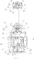
- Fig. 1 is a front view of a rotor driving system provided by an embodiment of the present invention
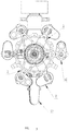
- Fig. 2 is a top view of a rotor driving system provided by an embodiment of the present invention
- Fig. 3 is a left view of a rotor driving system provided by an embodiment of the present invention
- Fig. 4 is a back view of a rotor driving system provided by an embodiment of the present invention
- Fig. 5 is a bottom view of a rotor driving system provided by an embodiment of the present invention
- Fig. 6 is a right view of a rotor driving system provided by an embodiment of the present invention
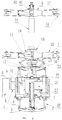
- Fig. 7 is a full section view of the front view of the rotor driving system provided by an embodiment of the present invention with its section plane being a plane through the center line of an inner shaft and perpendicular to the paper surface and the projection is leftward.
- the rotor driving system provided by the embodiments of the present invention is applicable to a twin-rotor coaxial autonomous helicopter.
- the rotor driving system may comprise:
- each of the first blade clamping bodies can be twisted relative to the lower rotor hub 14 and each of the second blade clamping bodies can be twisted relative to the upper rotor hub 16 under the action of a blade-clamp shaft, for example, a blade-clamp shaft 55 is provided within the second blade clamping body, enabling the second blade clamping body to twist relative to the upper rotor hub 16.
- a blade-clamp shaft 55 is provided within the second blade clamping body, enabling the second blade clamping body to twist relative to the upper rotor hub 16.
- the extension end 6 of the box body 27 is connected with the synchronous belt wheel 7 such that the synchronous belt wheel 7 can rotate smoothly under the action of an engine as a power device in the twin-rotor coaxial autonomous helicopter without being affected by other elements.
- the gear train housed in the box may comprise a conical-gear shaft 52, an upper conical gear 54 and a lower conical gear 50; wherein, the synchronous belt wheel 7 is connected with the conical-gear shaft 52 which in turn is respectively connected to the upper conical gear 54 and the lower conical gear 50, and the upper conical gear 54 is engaged with the outer shaft 19 and the lower conical gear 50 is connected with the inner shaft 15.
- a gear-shaft end cover 53 may be comprised, which is arranged on the extension end 6 of the box body 27 and severs for the axial locating of the conical-gear shaft 52.
- a rotor driving system applicable to a twin-rotor coaxial autonomous helicopter may comprise an upper-rotor driving system and a lower-rotor driving system; wherein, the lower-rotor driving system may comprise:
- the lower-rotor steering assembly can be constituted by two elements, for example, the lower-rotor steering assembly can be constituted by a anti-rotation plate 21 and a lower-rotor steering rod - L arm 23 as shown in Fig. 3 and 6 , wherein one end of the anti-rotation plate 21 is connected with one end of the lower-rotor steering rod - L arm 23 and the other end of the anti-rotation plate 21 is connected with the lower rotor hub 14, and the other end of the lower-rotor steering rod - L arm 23 is connected with the rotating lower-rotor swashplate 24.
- the lower-rotor steering assembly can also be constituted by one element, wherein one end of this element is connected with the lower rotor hub 14 and the other end is connected with the rotating lower-rotor swashplate 24; alternatively, it is also possible that the lower-rotor steering assembly can be constituted by at least three elements, by which the lower rotor hub 14 and the rotating lower-rotor swashplate 24 are connected with each other.
- the lengths of the first sliding block 44 and the second sliding block 30 can be set according to the actual situations.
- the first sliding block 44 may penetrate into the through hole of the first anti-rotation rod 25 but do not penetrate out of the through hole; alternatively, it is also possible that the first sliding block 44 may penetrate into and out of the through hole of the first anti-rotation rod 25; and the second sliding block 30 can penetrate into the through hole of the second anti-rotation rod 29 but do not penetrate out of the through hole; alternatively, it is also possible that the second sliding block 30 can penetrate into and out of the through hole of the second anti-rotation rod 29.
- connections between the elements described in the embodiments of the present invention can utilize, but is not limited to, a bearing connection or a threaded connection according to the actual application requirements.
- the connection between the nonrotating lower-rotor swashplate 11 and the rotating lower-rotor swashplate 24 and the connection between the nonrotating upper-rotor swashplate 3 and the rotating upper-rotor swashplate 4 can both utilize a bearing connection;
- the lower-rotor steering assembly can be connected with a bearing seat 12 of L-arm rod end that is connected to the rotating lower-rotor swashplate 24 and thus enabling the connection with the rotating lower-rotor swashplate 24;
- the lower upper-rotor steering rod 45 can be connected with the lower pull-rod plug 64 by a lower pull-rod joint bearing 32;
- the upper tilted-arm pull rod 41 can be connected to a bearing seat 36 of tilted-arm upper rod end that is connected to a blade-clamp tilted arm 42 of the upper rotor, thus enabling the
- the rotor driving system provided by the embodiments of the present invention can be connected with the frame of a twin-rotor coaxial autonomous helicopter by a first connection point 60, a second connection point 61, a third connection point 62 and a fourth connection point 63.
- first connection point 60 a first connection point 60
- second connection point 61 a second connection point 61
- third connection point 62 a fourth connection point 63.
- fourth connection point 63 a twin-rotor coaxial autonomous helicopter.
- the present invention is not limited to this.
- At least three first actuators 8 can drive a nonrotating lower-rotor swashplate 11 to tilt towards a specific direction by cooperating with each other (with first screw-rod sleeve rods 65 extending, shortening or stationary) such that a rotating lower-rotor swashplate 24, lower tilted-arm pull rods 35 and blade-clamp tilted arms 13 of the lower rotor are all in motion, thereby driving first blade clamping bodies to be twisted relative to a lower rotor hub 14; at least three second actuators 58 can cause a nonrotating upper-rotor swashplate 3 to tilt towards a specific direction by cooperating with each other (with second screw-rod sleeve rods 28 extending, shortening or stationary) such that a rotating upper-rotor swashplate 4, upper-rotor steering rod - L arms 47, lower upper-rotor steering rods 45, pull rods 56, upper upper-rotor steering rods 40, upper tilted-arm pull rods 41, blade-
- the upper-rotor driving system may include:
- shake caused when the upper upper-rotor steering rods 40 and the upper tilted-arm pull rods 41 rotate with the inner shaft 15 can be avoided by adding the upper inner-shaft head frame 37, and thus improving the structural stability; and the shake caused when the lower upper-rotor steering rods 45 rotate with the inner shaft 15 can be avoided by adding the lower inner-shaft head frame 31, and thus improving the structural stability.
- the lower-rotor driving system may further comprise: at least three first gearbox bodies 5, each of which is connected with a corresponding first motor 9, wherein, the rotational speed output by the corresponding first motor 9 is adjusted by each of the first gearbox bodies 5.
- the upper-rotor driving system may further comprise: at least three second gearbox bodies 43, each of which is connected with a corresponding second motor 49, wherein, the rotational speed output by the corresponding second motor 49 is adjusted by each of the second gearbox bodies 43.
- first gearbox body 5 and the second gearbox body 43 may be, but not be limited to, a gear type gearbox body or a chain type gearbox body.
- the selectivity of the first motor 9 is improved by providing a first gearbox body 5 for the first motor 9; and the selectivity of the second motor 49 is improved by providing a second gearbox body 43 for the second motor 49.
- a method for driving a rotor corresponding to the rotor driving system described above may comprise:
- the second screw-rod outer sleeve rod 28 of each of the second actuators 58 extends, shortens or remains stationary with rotation of the corresponding second motor 49 which can drive a nonrotating upper-rotor swashplate 3 in the upper-rotor driving system to tilt towards a specific direction and thus drive the rotating upper-rotor swashplate 4, the at least two upper-rotor steering rods - L arms 47, the at least two lower upper-rotor steering rods 45, the at least two pull rods 56 within the inner shaft 15, the at least two upper upper-rotor steering rods 40, the at least two upper tilted-arm pull rods 41 and at least two blade-clamp tilted arms 42 of the upper rotor to move, thus enabling the second blade clamping bodies to be twisted relative to the upper rotor hub 16.
- the second screw-rod outer sleeve rod 28 of the second motor 58 will remain stationary (i.e., neither extends nor shortens) with rotation of the corresponding second actuator 58 when the second rotational state of the second motor 58 and the current rotational state thereof are the same; and the second screw-rod outer sleeve rod 28 of the second motor 58 will extend or shorten with rotation of the corresponding second actuator 58 when the second rotational state of the second motor 58 and the current rotational state thereof are different.
- rotation of the lower rotor hub 14 with the outer shaft 19 drives the rotating lower-rotor swashplate 24 to rotate under the action of the at least two lower-rotor steering assemblies in the lower-rotor driving system; rotation of the upper rotor hub 16 with the inner shaft 15 drives the rotating upper-rotor swashplate 4 to rotate under the action of the upper-rotor steering rods - L arms 47 and the lower upper-rotor steering rods 45.
- the nonrotating lower-rotor swashplate 11 is not rotatable with the rotating lower-rotor swashplate 24 under the action of the first anti-rotation rod 25 and the first sliding block 44 in the lower rotor driving system; the nonrotating upper-rotor swashplate 3 is not rotatable with the rotating upper-rotor swashplate 4 under the action of the second anti-rotation rod 29 and the second sliding block 30 in the upper-rotor driving system.
- the step of determining the required first rotational states of the first motors 9 according to the command for flight control and the current rotational states of the first motors 9 may comprise:
- the required first rotational state of each of the first motors 9 can be determined according to a pre-built corresponding relationship between the twist angle by which each of the first blade clamping bodies rotates relative to the lower rotor hub 14 and the rotational states of the first motors 9 after determining the required first twist angle by which each of the first blade clamping bodies rotates relative to the lower rotor hub 14. Wherein, the required first rotational states of various first motors 9 can be the same or different.
- the step of determining the required second rotational states of the second motors 49 according to the command for flight control and the current rotational states of the second motors 10 may comprise:
- the required second rotational state of each of the second motors 49 can be determined according to the pre-established corresponding relationship between the twist angle by which each of the second blade clamping bodies rotates relative to the upper rotor hub 16 and the rotational states of the second motors 49 after the required second twist angle by which each of the second blade clamping bodies rotates relative to the upper rotor hub 16.
- the second rotational states of various second motors 49 can be the same or different.
- the rotor driving method provided by the embodiments of the present invention enables to control the telescopic ability of the screw-rod sleeve rod in the actuator connected with the rotor such that various elements between the screw-rod sleeve rod and a blade clamping body can interact so as to drive the blade clamping body to be twisted relative to the hub, thus reducing the complexity of the rotor driving process and solving the drawback of complex driving process present in the existing rotor driving method of rotor driving system.
Landscapes
- Engineering & Computer Science (AREA)
- Mechanical Engineering (AREA)
- Aviation & Aerospace Engineering (AREA)
- Chemical & Material Sciences (AREA)
- Combustion & Propulsion (AREA)
- Remote Sensing (AREA)
- Transmission Devices (AREA)
- Catching Or Destruction (AREA)
- Structures Of Non-Positive Displacement Pumps (AREA)
- Wind Motors (AREA)
Applications Claiming Priority (1)
| Application Number | Priority Date | Filing Date | Title |
|---|---|---|---|
| PCT/CN2013/085745 WO2015058364A1 (zh) | 2013-10-23 | 2013-10-23 | 旋翼驱动系统 |
Publications (3)
| Publication Number | Publication Date |
|---|---|
| EP3061688A1 EP3061688A1 (en) | 2016-08-31 |
| EP3061688A4 EP3061688A4 (en) | 2017-07-19 |
| EP3061688B1 true EP3061688B1 (en) | 2018-09-05 |
Family
ID=52992130
Family Applications (1)
| Application Number | Title | Priority Date | Filing Date |
|---|---|---|---|
| EP13895830.1A Active EP3061688B1 (en) | 2013-10-23 | 2013-10-23 | Rotor driving system |
Country Status (7)
| Country | Link |
|---|---|
| US (1) | US10081423B2 (https=) |
| EP (1) | EP3061688B1 (https=) |
| JP (1) | JP6099836B2 (https=) |
| AU (2) | AU2013403751B2 (https=) |
| BR (1) | BR112016008922B1 (https=) |
| RU (1) | RU2641396C2 (https=) |
| WO (1) | WO2015058364A1 (https=) |
Families Citing this family (3)
| Publication number | Priority date | Publication date | Assignee | Title |
|---|---|---|---|---|
| CN106915457B (zh) * | 2017-02-22 | 2019-05-17 | 北京航空航天大学 | 一种上下旋翼倾斜器平行度可变的共轴式直升机操纵系统 |
| CN109533322B (zh) * | 2018-11-15 | 2020-09-25 | 中国直升机设计研究所 | 一种自动倾斜器 |
| CN112173099A (zh) * | 2020-11-26 | 2021-01-05 | 尚良仲毅(沈阳)高新科技有限公司 | 一种用于无人机的变距装置、变距控制方法及无人机 |
Family Cites Families (6)
| Publication number | Priority date | Publication date | Assignee | Title |
|---|---|---|---|---|
| ES8102955A1 (es) * | 1980-04-18 | 1981-02-16 | Campos Herruzo Juan | Sistema control de direccion de helicoptero coaxial, paso colectivo a la vez que tambien variable simultaneamente con signo contrario |
| RU2155702C1 (ru) * | 1999-04-15 | 2000-09-10 | Кумертауское авиационное производственное предприятие | Система двух соосных несущих винтов летательного аппарата |
| DE102007002586A1 (de) * | 2007-01-12 | 2008-07-24 | Rotorfly Ltd. | Rotorsystem |
| RU2485017C2 (ru) * | 2011-08-24 | 2013-06-20 | Сергей Александрович Задорожный | Механизм автомата перекоса вертолета |
| CN102658865B (zh) * | 2012-05-17 | 2014-05-28 | 李游 | 共轴反转旋翼直升机的共轴传动和控制结构 |
| CN103318407B (zh) * | 2013-06-05 | 2016-08-31 | 北京深远世宁科技有限公司 | 一种共轴式双旋翼无人直升机操纵系统的分立控制系统 |
-
2013
- 2013-10-23 RU RU2016117177A patent/RU2641396C2/ru active
- 2013-10-23 AU AU2013403751A patent/AU2013403751B2/en active Active
- 2013-10-23 US US15/031,467 patent/US10081423B2/en active Active
- 2013-10-23 EP EP13895830.1A patent/EP3061688B1/en active Active
- 2013-10-23 JP JP2016549603A patent/JP6099836B2/ja active Active
- 2013-10-23 BR BR112016008922-7A patent/BR112016008922B1/pt active IP Right Grant
- 2013-10-23 WO PCT/CN2013/085745 patent/WO2015058364A1/zh not_active Ceased
-
2016
- 2016-04-29 AU AU2016100487A patent/AU2016100487A4/en not_active Expired
Non-Patent Citations (1)
| Title |
|---|
| None * |
Also Published As
| Publication number | Publication date |
|---|---|
| BR112016008922A2 (https=) | 2017-08-01 |
| BR112016008922B1 (pt) | 2021-09-14 |
| JP6099836B2 (ja) | 2017-03-22 |
| US10081423B2 (en) | 2018-09-25 |
| EP3061688A1 (en) | 2016-08-31 |
| US20160264238A1 (en) | 2016-09-15 |
| WO2015058364A1 (zh) | 2015-04-30 |
| AU2016100487A4 (en) | 2016-06-09 |
| RU2641396C2 (ru) | 2018-01-17 |
| AU2013403751A1 (en) | 2016-05-19 |
| AU2013403751B2 (en) | 2016-12-01 |
| EP3061688A4 (en) | 2017-07-19 |
| RU2016117177A (ru) | 2017-11-28 |
| JP2016538196A (ja) | 2016-12-08 |
Similar Documents
| Publication | Publication Date | Title |
|---|---|---|
| US9199729B1 (en) | Coaxial counter-rotating unmanned helicopter | |
| CN204223182U (zh) | 民用无人直升机旋翼控制倾斜盘驱动装置 | |
| EP3159262B1 (en) | Inter-rotor blade pitch control device of coaxial double-rotor helicopter | |
| CN106477032B (zh) | 多轴飞行器 | |
| CA2749119C (en) | Improved rotor-blade control system and method | |
| CN103158870A (zh) | 具有反馈杆的桨叶俯仰控制系统 | |
| AU2016100487A4 (en) | Rotor driving system | |
| KR20130077242A (ko) | 무인항공기의 틸팅 시스템 | |
| JP2018052227A (ja) | ピッチ変更機構及び可変ピッチ型回転翼機構 | |
| CN110901908A (zh) | 一种两舵机定轴变距旋翼模块及直升机 | |
| JP2009051381A (ja) | サイクロイダル・ブレード | |
| US9845149B2 (en) | Method and device for driving rotor | |
| CN116395162A (zh) | 一种共轴双旋翼飞行器及其控制方法 | |
| CN109466749B (zh) | 直升机变距驱动总成及直升机 | |
| CN105599893A (zh) | 一种変距螺旋桨机构 | |
| CN110920874B (zh) | 一种三舵机定轴变距旋翼模块及直升机 | |
| CN109436299B (zh) | 直升机尾桨星形变距机构及直升机 | |
| CN211731804U (zh) | 一种三舵机定轴变距旋翼模块及直升机 | |
| CN105480409A (zh) | 涵道动力装置及飞行器 | |
| CN113815853B (zh) | 一种旋翼推进装置及控制方法 | |
| CN221820276U (zh) | 一种共轴双旋翼无人机及其操控机构 | |
| CN113911337A (zh) | 一种自动倾斜器控制系统及其操控方法 | |
| CN109018431A (zh) | 一种主旋翼试验机自动倾斜器双螺旋锁紧器 | |
| JPS6212499A (ja) | 二重反転式ヘリコプタの動力伝達装置 |
Legal Events
| Date | Code | Title | Description |
|---|---|---|---|
| PUAI | Public reference made under article 153(3) epc to a published international application that has entered the european phase |
Free format text: ORIGINAL CODE: 0009012 |
|
| 17P | Request for examination filed |
Effective date: 20160426 |
|
| AK | Designated contracting states |
Kind code of ref document: A1 Designated state(s): AL AT BE BG CH CY CZ DE DK EE ES FI FR GB GR HR HU IE IS IT LI LT LU LV MC MK MT NL NO PL PT RO RS SE SI SK SM TR |
|
| AX | Request for extension of the european patent |
Extension state: BA ME |
|
| DAX | Request for extension of the european patent (deleted) | ||
| A4 | Supplementary search report drawn up and despatched |
Effective date: 20170621 |
|
| RIC1 | Information provided on ipc code assigned before grant |
Ipc: B64C 27/10 20060101AFI20170614BHEP Ipc: B64C 27/605 20060101ALI20170614BHEP Ipc: B64C 27/12 20060101ALI20170614BHEP |
|
| GRAP | Despatch of communication of intention to grant a patent |
Free format text: ORIGINAL CODE: EPIDOSNIGR1 |
|
| STAA | Information on the status of an ep patent application or granted ep patent |
Free format text: STATUS: GRANT OF PATENT IS INTENDED |
|
| RIC1 | Information provided on ipc code assigned before grant |
Ipc: B64C 27/12 20060101ALI20180227BHEP Ipc: B64C 27/10 20060101AFI20180227BHEP Ipc: B64C 27/605 20060101ALI20180227BHEP |
|
| INTG | Intention to grant announced |
Effective date: 20180403 |
|
| GRAS | Grant fee paid |
Free format text: ORIGINAL CODE: EPIDOSNIGR3 |
|
| GRAA | (expected) grant |
Free format text: ORIGINAL CODE: 0009210 |
|
| STAA | Information on the status of an ep patent application or granted ep patent |
Free format text: STATUS: THE PATENT HAS BEEN GRANTED |
|
| AK | Designated contracting states |
Kind code of ref document: B1 Designated state(s): AL AT BE BG CH CY CZ DE DK EE ES FI FR GB GR HR HU IE IS IT LI LT LU LV MC MK MT NL NO PL PT RO RS SE SI SK SM TR |
|
| REG | Reference to a national code |
Ref country code: GB Ref legal event code: FG4D |
|
| REG | Reference to a national code |
Ref country code: CH Ref legal event code: EP |
|
| REG | Reference to a national code |
Ref country code: AT Ref legal event code: REF Ref document number: 1037491 Country of ref document: AT Kind code of ref document: T Effective date: 20180915 |
|
| REG | Reference to a national code |
Ref country code: IE Ref legal event code: FG4D |
|
| REG | Reference to a national code |
Ref country code: DE Ref legal event code: R096 Ref document number: 602013043405 Country of ref document: DE |
|
| REG | Reference to a national code |
Ref country code: FR Ref legal event code: PLFP Year of fee payment: 6 |
|
| REG | Reference to a national code |
Ref country code: NL Ref legal event code: MP Effective date: 20180905 |
|
| REG | Reference to a national code |
Ref country code: LT Ref legal event code: MG4D |
|
| PG25 | Lapsed in a contracting state [announced via postgrant information from national office to epo] |
Ref country code: BG Free format text: LAPSE BECAUSE OF FAILURE TO SUBMIT A TRANSLATION OF THE DESCRIPTION OR TO PAY THE FEE WITHIN THE PRESCRIBED TIME-LIMIT Effective date: 20181205 Ref country code: RS Free format text: LAPSE BECAUSE OF FAILURE TO SUBMIT A TRANSLATION OF THE DESCRIPTION OR TO PAY THE FEE WITHIN THE PRESCRIBED TIME-LIMIT Effective date: 20180905 Ref country code: LT Free format text: LAPSE BECAUSE OF FAILURE TO SUBMIT A TRANSLATION OF THE DESCRIPTION OR TO PAY THE FEE WITHIN THE PRESCRIBED TIME-LIMIT Effective date: 20180905 Ref country code: NO Free format text: LAPSE BECAUSE OF FAILURE TO SUBMIT A TRANSLATION OF THE DESCRIPTION OR TO PAY THE FEE WITHIN THE PRESCRIBED TIME-LIMIT Effective date: 20181205 Ref country code: FI Free format text: LAPSE BECAUSE OF FAILURE TO SUBMIT A TRANSLATION OF THE DESCRIPTION OR TO PAY THE FEE WITHIN THE PRESCRIBED TIME-LIMIT Effective date: 20180905 Ref country code: GR Free format text: LAPSE BECAUSE OF FAILURE TO SUBMIT A TRANSLATION OF THE DESCRIPTION OR TO PAY THE FEE WITHIN THE PRESCRIBED TIME-LIMIT Effective date: 20181206 Ref country code: SE Free format text: LAPSE BECAUSE OF FAILURE TO SUBMIT A TRANSLATION OF THE DESCRIPTION OR TO PAY THE FEE WITHIN THE PRESCRIBED TIME-LIMIT Effective date: 20180905 |
|
| REG | Reference to a national code |
Ref country code: AT Ref legal event code: MK05 Ref document number: 1037491 Country of ref document: AT Kind code of ref document: T Effective date: 20180905 |
|
| PG25 | Lapsed in a contracting state [announced via postgrant information from national office to epo] |
Ref country code: LV Free format text: LAPSE BECAUSE OF FAILURE TO SUBMIT A TRANSLATION OF THE DESCRIPTION OR TO PAY THE FEE WITHIN THE PRESCRIBED TIME-LIMIT Effective date: 20180905 Ref country code: AL Free format text: LAPSE BECAUSE OF FAILURE TO SUBMIT A TRANSLATION OF THE DESCRIPTION OR TO PAY THE FEE WITHIN THE PRESCRIBED TIME-LIMIT Effective date: 20180905 Ref country code: HR Free format text: LAPSE BECAUSE OF FAILURE TO SUBMIT A TRANSLATION OF THE DESCRIPTION OR TO PAY THE FEE WITHIN THE PRESCRIBED TIME-LIMIT Effective date: 20180905 |
|
| PG25 | Lapsed in a contracting state [announced via postgrant information from national office to epo] |
Ref country code: PL Free format text: LAPSE BECAUSE OF FAILURE TO SUBMIT A TRANSLATION OF THE DESCRIPTION OR TO PAY THE FEE WITHIN THE PRESCRIBED TIME-LIMIT Effective date: 20180905 Ref country code: EE Free format text: LAPSE BECAUSE OF FAILURE TO SUBMIT A TRANSLATION OF THE DESCRIPTION OR TO PAY THE FEE WITHIN THE PRESCRIBED TIME-LIMIT Effective date: 20180905 Ref country code: AT Free format text: LAPSE BECAUSE OF FAILURE TO SUBMIT A TRANSLATION OF THE DESCRIPTION OR TO PAY THE FEE WITHIN THE PRESCRIBED TIME-LIMIT Effective date: 20180905 Ref country code: IS Free format text: LAPSE BECAUSE OF FAILURE TO SUBMIT A TRANSLATION OF THE DESCRIPTION OR TO PAY THE FEE WITHIN THE PRESCRIBED TIME-LIMIT Effective date: 20190105 Ref country code: IT Free format text: LAPSE BECAUSE OF FAILURE TO SUBMIT A TRANSLATION OF THE DESCRIPTION OR TO PAY THE FEE WITHIN THE PRESCRIBED TIME-LIMIT Effective date: 20180905 Ref country code: RO Free format text: LAPSE BECAUSE OF FAILURE TO SUBMIT A TRANSLATION OF THE DESCRIPTION OR TO PAY THE FEE WITHIN THE PRESCRIBED TIME-LIMIT Effective date: 20180905 Ref country code: ES Free format text: LAPSE BECAUSE OF FAILURE TO SUBMIT A TRANSLATION OF THE DESCRIPTION OR TO PAY THE FEE WITHIN THE PRESCRIBED TIME-LIMIT Effective date: 20180905 Ref country code: NL Free format text: LAPSE BECAUSE OF FAILURE TO SUBMIT A TRANSLATION OF THE DESCRIPTION OR TO PAY THE FEE WITHIN THE PRESCRIBED TIME-LIMIT Effective date: 20180905 Ref country code: CZ Free format text: LAPSE BECAUSE OF FAILURE TO SUBMIT A TRANSLATION OF THE DESCRIPTION OR TO PAY THE FEE WITHIN THE PRESCRIBED TIME-LIMIT Effective date: 20180905 |
|
| PG25 | Lapsed in a contracting state [announced via postgrant information from national office to epo] |
Ref country code: PT Free format text: LAPSE BECAUSE OF FAILURE TO SUBMIT A TRANSLATION OF THE DESCRIPTION OR TO PAY THE FEE WITHIN THE PRESCRIBED TIME-LIMIT Effective date: 20190105 Ref country code: SM Free format text: LAPSE BECAUSE OF FAILURE TO SUBMIT A TRANSLATION OF THE DESCRIPTION OR TO PAY THE FEE WITHIN THE PRESCRIBED TIME-LIMIT Effective date: 20180905 Ref country code: SK Free format text: LAPSE BECAUSE OF FAILURE TO SUBMIT A TRANSLATION OF THE DESCRIPTION OR TO PAY THE FEE WITHIN THE PRESCRIBED TIME-LIMIT Effective date: 20180905 |
|
| REG | Reference to a national code |
Ref country code: CH Ref legal event code: PL |
|
| REG | Reference to a national code |
Ref country code: DE Ref legal event code: R097 Ref document number: 602013043405 Country of ref document: DE |
|
| REG | Reference to a national code |
Ref country code: BE Ref legal event code: MM Effective date: 20181031 |
|
| PG25 | Lapsed in a contracting state [announced via postgrant information from national office to epo] |
Ref country code: LU Free format text: LAPSE BECAUSE OF NON-PAYMENT OF DUE FEES Effective date: 20181023 |
|
| PLBE | No opposition filed within time limit |
Free format text: ORIGINAL CODE: 0009261 |
|
| STAA | Information on the status of an ep patent application or granted ep patent |
Free format text: STATUS: NO OPPOSITION FILED WITHIN TIME LIMIT |
|
| REG | Reference to a national code |
Ref country code: IE Ref legal event code: MM4A |
|
| PG25 | Lapsed in a contracting state [announced via postgrant information from national office to epo] |
Ref country code: DK Free format text: LAPSE BECAUSE OF FAILURE TO SUBMIT A TRANSLATION OF THE DESCRIPTION OR TO PAY THE FEE WITHIN THE PRESCRIBED TIME-LIMIT Effective date: 20180905 Ref country code: MC Free format text: LAPSE BECAUSE OF FAILURE TO SUBMIT A TRANSLATION OF THE DESCRIPTION OR TO PAY THE FEE WITHIN THE PRESCRIBED TIME-LIMIT Effective date: 20180905 |
|
| 26N | No opposition filed |
Effective date: 20190606 |
|
| GBPC | Gb: european patent ceased through non-payment of renewal fee |
Effective date: 20181205 |
|
| PG25 | Lapsed in a contracting state [announced via postgrant information from national office to epo] |
Ref country code: SI Free format text: LAPSE BECAUSE OF FAILURE TO SUBMIT A TRANSLATION OF THE DESCRIPTION OR TO PAY THE FEE WITHIN THE PRESCRIBED TIME-LIMIT Effective date: 20180905 Ref country code: LI Free format text: LAPSE BECAUSE OF NON-PAYMENT OF DUE FEES Effective date: 20181031 Ref country code: CH Free format text: LAPSE BECAUSE OF NON-PAYMENT OF DUE FEES Effective date: 20181031 Ref country code: BE Free format text: LAPSE BECAUSE OF NON-PAYMENT OF DUE FEES Effective date: 20181031 |
|
| PG25 | Lapsed in a contracting state [announced via postgrant information from national office to epo] |
Ref country code: IE Free format text: LAPSE BECAUSE OF NON-PAYMENT OF DUE FEES Effective date: 20181023 |
|
| PG25 | Lapsed in a contracting state [announced via postgrant information from national office to epo] |
Ref country code: GB Free format text: LAPSE BECAUSE OF NON-PAYMENT OF DUE FEES Effective date: 20181205 |
|
| PG25 | Lapsed in a contracting state [announced via postgrant information from national office to epo] |
Ref country code: MT Free format text: LAPSE BECAUSE OF NON-PAYMENT OF DUE FEES Effective date: 20181023 |
|
| PG25 | Lapsed in a contracting state [announced via postgrant information from national office to epo] |
Ref country code: TR Free format text: LAPSE BECAUSE OF FAILURE TO SUBMIT A TRANSLATION OF THE DESCRIPTION OR TO PAY THE FEE WITHIN THE PRESCRIBED TIME-LIMIT Effective date: 20180905 |
|
| PG25 | Lapsed in a contracting state [announced via postgrant information from national office to epo] |
Ref country code: CY Free format text: LAPSE BECAUSE OF FAILURE TO SUBMIT A TRANSLATION OF THE DESCRIPTION OR TO PAY THE FEE WITHIN THE PRESCRIBED TIME-LIMIT Effective date: 20180905 Ref country code: MK Free format text: LAPSE BECAUSE OF NON-PAYMENT OF DUE FEES Effective date: 20180905 Ref country code: HU Free format text: LAPSE BECAUSE OF FAILURE TO SUBMIT A TRANSLATION OF THE DESCRIPTION OR TO PAY THE FEE WITHIN THE PRESCRIBED TIME-LIMIT; INVALID AB INITIO Effective date: 20131023 |
|
| REG | Reference to a national code |
Ref country code: DE Ref legal event code: R082 Ref document number: 602013043405 Country of ref document: DE Representative=s name: KANDLBINDER, MARKUS, DIPL.-PHYS., DE |
|
| PGFP | Annual fee paid to national office [announced via postgrant information from national office to epo] |
Ref country code: DE Payment date: 20251021 Year of fee payment: 13 |
|
| PGFP | Annual fee paid to national office [announced via postgrant information from national office to epo] |
Ref country code: FR Payment date: 20251030 Year of fee payment: 13 |