EP3061675A1 - Dichtstopfen, baugruppe und verfahren zum abdichten einer öffnung - Google Patents
Dichtstopfen, baugruppe und verfahren zum abdichten einer öffnung Download PDFInfo
- Publication number
- EP3061675A1 EP3061675A1 EP16150556.5A EP16150556A EP3061675A1 EP 3061675 A1 EP3061675 A1 EP 3061675A1 EP 16150556 A EP16150556 A EP 16150556A EP 3061675 A1 EP3061675 A1 EP 3061675A1
- Authority
- EP
- European Patent Office
- Prior art keywords
- opening
- sealing
- sealing plug
- component
- lip
- Prior art date
- Legal status (The legal status is an assumption and is not a legal conclusion. Google has not performed a legal analysis and makes no representation as to the accuracy of the status listed.)
- Granted
Links
Images


Classifications
-
- F—MECHANICAL ENGINEERING; LIGHTING; HEATING; WEAPONS; BLASTING
- F16—ENGINEERING ELEMENTS AND UNITS; GENERAL MEASURES FOR PRODUCING AND MAINTAINING EFFECTIVE FUNCTIONING OF MACHINES OR INSTALLATIONS; THERMAL INSULATION IN GENERAL
- F16J—PISTONS; CYLINDERS; SEALINGS
- F16J15/00—Sealings
- F16J15/02—Sealings between relatively-stationary surfaces
- F16J15/06—Sealings between relatively-stationary surfaces with solid packing compressed between sealing surfaces
-
- B—PERFORMING OPERATIONS; TRANSPORTING
- B62—LAND VEHICLES FOR TRAVELLING OTHERWISE THAN ON RAILS
- B62D—MOTOR VEHICLES; TRAILERS
- B62D25/00—Superstructure or monocoque structure sub-units; Parts or details thereof not otherwise provided for
- B62D25/24—Superstructure sub-units with access or drainage openings having movable or removable closures; Sealing means therefor
-
- B—PERFORMING OPERATIONS; TRANSPORTING
- B05—SPRAYING OR ATOMISING IN GENERAL; APPLYING FLUENT MATERIALS TO SURFACES, IN GENERAL
- B05C—APPARATUS FOR APPLYING FLUENT MATERIALS TO SURFACES, IN GENERAL
- B05C21/00—Accessories or implements for use in connection with applying liquids or other fluent materials to surfaces, not provided for in groups B05C1/00 - B05C19/00
- B05C21/005—Masking devices
-
- F—MECHANICAL ENGINEERING; LIGHTING; HEATING; WEAPONS; BLASTING
- F16—ENGINEERING ELEMENTS AND UNITS; GENERAL MEASURES FOR PRODUCING AND MAINTAINING EFFECTIVE FUNCTIONING OF MACHINES OR INSTALLATIONS; THERMAL INSULATION IN GENERAL
- F16J—PISTONS; CYLINDERS; SEALINGS
- F16J15/00—Sealings
- F16J15/02—Sealings between relatively-stationary surfaces
- F16J15/06—Sealings between relatively-stationary surfaces with solid packing compressed between sealing surfaces
- F16J15/062—Sealings between relatively-stationary surfaces with solid packing compressed between sealing surfaces characterised by the geometry of the seat
Definitions
- the invention relates to a sealing plug for closing an opening in a component, in particular a body component of a motor vehicle. Moreover, the invention relates to an assembly with such a sealing plug and a method for sealing an opening.
- openings in various body components In the manufacture of vehicle bodies, it is necessary to seal openings in various body components to prevent ingress of dirt or water. These openings are for example only closed when the respective body component is transferred during the painting process for melting and curing of the applied paint in a heating furnace.
- sealing plugs are used which are inserted into the opening of the body component and which are fixed for example by means of suitable locking elements which engage in the opening of the component.
- the plug can simultaneously seal the opening, e.g. It is known to permanently bond at least a portion of the sealing plug with the edge of the opening.
- a portion of the sealing plug is made of a material melting or expanding under the influence of temperature, so that when the component is heated, e.g. when painting, the sealing plug is firmly bonded to the edge of the opening.
- the opening is sealed watertight and at the same time attached to the sealing plug on the body part.
- Such a sealing plug is for example in the DE 602 04 131 T2 shown, wherein there are two concentric rings of melting material, which are interconnected by a plurality of ribs, wherein the radially outer ring rests next to the edge of the opening and the radially inner ring rests against the inner edge of the opening.
- sealing plug must be adapted to the diameter of the opening rather exactly, and so prefabricated for different opening diameter a variety of sealing plugs and must be kept in stock.
- the object of the invention is to provide a sealing plug which can be used for openings with different diameters.
- a sealing plug for closing an opening in a component, in particular a body component of a motor vehicle, having a base body which is formed so that it can cover the opening and engage behind an edge of the opening, wherein the base body, a sealing body is arranged, which has a ring portion and a plurality of annular portion of the projecting, circumferentially flexible lamellae with free radial ends. Due to their mobility in the circumferential direction, the lamellae can rest more or less against the ring section and thus make it possible for the sealing body to be inserted into openings of different diameters, the lamellae always resting against the inner edge of the opening.
- the diameter range depends on the length of the slats.
- a minimum diameter is defined by the fact that, when the sealing plug is inserted, the lamellae lie almost completely against the ring section, while the maximum diameter is determined by the fact that the lamellae project as far as possible radially outward.
- the fins are preferably elastic and thus exert a restoring force in the circumferential and radial directions, which ensures that the sealing plug jams in the opening and also causes a centering of the sealing plug in the opening.
- the material of the sealing body should be elastic for this purpose.
- the lamellae preferably extend in the plane of the ring portion, so that when inserted into the opening sealing plug and the ring portion is at the level of the inner edge of the opening.
- the lamellae preferably extend over the entire axial length of the ring section.
- the main body has a circumferential support lip and a circumferential locking lip for engagement with a front side and a rear side of the component, wherein the sealing body is received between the support lip and the locking lip.
- the lamellae are preferably also completely received in the space formed by the lips and are protected by them.
- the lips run obliquely and each form a truncated cone.
- the locking lip should engage behind the rear edge of the opening in the mounted state, thus allowing a locking of the entire sealing plug when inserted in the desired position.
- the main body may have a peripheral peripheral wall and the sealing body, in particular its annular portion, bear radially on the outside of the peripheral wall. This design allows a stable radial support of the sealing body and generates sufficient back pressure to fix the sealing plug when inserted into the opening.
- the slats are chamfered at their free radial ends on rastlippenschen axial end, this chamfer facilitates folding over in the circumferential direction during insertion of the sealing plug into the opening.
- this chamfer facilitates folding over in the circumferential direction during insertion of the sealing plug into the opening.
- the lamellae are unloaded at an angle of about 10 - 40 °, in particular at an angle of about 30 °, aligned with the radial direction. It has been found that in this way a simple folding takes place in the circumferential direction, since the slats are already unloaded at an angle to the radial direction, which predetermines a force component in the circumferential direction when inserted into the opening.
- the sealing body including the lamellae, preferably consists of a material which expands when exposed to heat.
- the amount of expanding sealing material is advantageously dimensioned so that when exposed to heat, for example, about 120 - 180 ° C, the space between the support lip and the locking lip and around the edge of the opening is completely filled.
- a sufficient amount of sealing material is provided in order to completely fill the space enclosed by the support lip and the locking lip, even at the maximum opening diameter provided.
- the sealing material fills the diameter of the opening from the peripheral wall of the sealing plug to the inner edge of the opening and also covers portions of the component radially outward of the opening on both the front and rear sides of the component. In this way, a circumferentially closed watertight seal is achieved.
- the expansion of the sealing body takes place, for example, during heating during painting.
- the base body should be formed of an elastic, but dimensionally stable material and is preferably integrally formed.
- a semi-rigid plastic material of a Shore D hardness of 30 - 50 is suitable, for example TEE or TPE or another suitable thermoplastic elastomer.
- the sealing body may be manufactured together with the base body in a two-component injection molding process in order to simplify the production.
- the invention also relates to an assembly with a sealing plug for closing an opening in a component, in particular a body component of a motor vehicle, and a component having an opening, wherein the sealing plug has a base body which is formed so as to cover the opening and an inner edge can engage behind the opening, wherein the base body, a sealing body is arranged, which has a heat-expanding material, wherein after heating the sealing plug, the expanding material upon heat the inner edge of the opening and radially adjacent portions of a front and a back of the component over the entire circumference encloses the opening.
- the sealing body may, as described above, have outwardly projecting fins, but could also be shaped differently. After insertion of the sealing plug into the opening and subsequent heating, the expanding sealing material fills the space around the inner edge of the opening completely and preferably without cavities, thus sealing the opening.
- the invention also relates to a method for sealing an opening in a component.
- a sealing plug described above which has a front-side support lip and a rear-side locking lip, inserted into the opening of the component, so that the rear-side locking lip engages behind the edge of the opening.
- the lamellae of the sealing body are deformed in the circumferential direction and center the sealing plug in the opening.
- the component is heated, which expands when exposed to heat material of the sealing body and surrounds the inner edge of the opening and radially adjacent areas of the front and the back of the component and completely fills the space formed between the support lip, the locking lip and the component.
- the support lip and the latching lip hold the sealing plug in position during heating.
- the sealing material completely fills the space between the lips so that no voids remain within the space enclosed by the support lip and the detent lip, which reduces the risk of corrosion.
- the pull-out force can be greater than 400 N.
- FIG. 1 shows a sealing plug 10, which has a base body 12 and a sealing body 14 arranged on the base body.
- the sealing plug 10 consists of these two components.
- the main body 12 has a circumferentially encircling support lip 16 and a circumferentially circumferential locking lip 18, both of which run obliquely along the radial direction r.
- the support lip 16 extends in the radial direction r further outward than the locking lip 18th
- Support lip 16 and locking lip 18 are integrally connected to each other via a peripheral wall 20.
- the support lip 16 merges integrally into a cover section 22, so that the support lip 16 and the cover section 22 together form a closed surface.
- the sealing body 14 consists of a circumferentially closed ring portion 24 and a plurality of outwardly projecting from the ring portion 24 fins 26 with free radial ends 28.
- the fins 26 extend here over the entire axial height of the annular portion 24.
- the fins 26 are integral with the ring portion 24 shaped. In this example, 10 fins are distributed around the circumference of the annular portion 24, but the number of fins 26 may be varied at the discretion of those skilled in the art.
- the fins 26 do not extend exactly in the radial direction r away from the ring portion 24, but are inclined at an angle of about 30 ° relative to the radial direction r (see, for example FIG. 1 ).
- the ring portion 24 is disposed radially outwardly adjacent to the peripheral wall 20 of the body.
- the entire sealing plug 10 is made in one piece in a two-component injection molding process.
- the material used for the base body in this example is a semi-rigid, dimensionally stable but elastic material, for example a TEE or a TPE (available under the trade name Arnitel®) or another suitable thermoplastic elastomer, in particular having a Shore D hardness of 30 - 50.
- the sealing body 14 here consists of a heat-expanding material, wherein any known, suitable material which increases its volume at a temperature between about 120-180 ° C can be used.
- all lamellae 26 have a chamfer 32.
- the angle of the chamfer 32 is selected to be approximately the same as the angle in which the latching lip 18 is aligned in a relaxed state with respect to the axial direction A (see, for example Figures 1 and 2 ).
- FIGS. 2 to 4 show the insertion of the sealing plug 10 in an opening 34 of a component 36 at normal room temperature before heating the sealing plug 10th
- the sealing plug 10 is inserted with the locking lip 18 first in the opening 34 (see FIG. 2 ), wherein the locking lip 18 first comes into contact with the inner edge 38 of the opening 34.
- the locking lip 18 is thereby deformed radially inwardly while it is pushed through the opening 34.
- FIG. 3 can be seen, the locking lip 18 in abutment with the chamfer 32 of the slats 26th
- the respective blade 26 Due to the already existing angle ⁇ to the radial direction r when force is applied in the axial direction A, the respective blade 26 is folded in the circumferential direction U, whereby the effective diameter of the sealing body 14 is reduced and adapts to the diameter d of the opening 34.
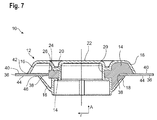
- the locking lip 18 After the locking lip 18 has passed the edge of the opening 34, it engages behind this on a rear side 40 of the component 36 (see FIGS. 4 and 7 ). In this case, the locking lip 18 releases again from the slats 26, and these relax due to their inherent elasticity until the free radial ends 28 of the slats 26 come into contact with the inner edge 38 of the opening 34. In this way, the sealing plug 10 is centered in the opening 34.
- the sealing plug 10 is designed for use in openings 34 with different diameters d between a minimum diameter and a maximum diameter d max .
- the slats deform more or less in the circumferential direction U.
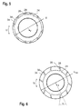
- FIG. 5 shows the situation in an opening 34 near the minimum diameter, where the lamellae 26 are folded at a nearly maximum angle to the radial direction r
- FIG. 6 shows the situation in an opening 34 with a maximum diameter d max where the fins 26 are almost in their unloaded condition.
- the slats 26 abut surface on the outer circumference of the annular portion 24, but it is achieved a better centering effect when the slats 26 still have some play.
- the diameter d of the opening 34 is always chosen larger than the outer diameter of the annular portion 24 and smaller than a diameter d max described by the free radial ends 28 of the fins 26 (see also FIG FIGS. 5 and 6 ).
- opening diameters d of approximately 30-35 mm can thus be covered, wherein the length of the lamellae 26, measured along their extent starting from the circumference of the annular section 24, can be approximately 3-5 mm.
- the component 36 is heated together with the sealing plug 10 used.
- the material of the sealing body 14 expands.
- the amount of material of the sealing body 14 is dimensioned so that the space enclosed by the peripheral wall 20, the support lip 16 and the locking lip 18 is completely filled by the now expanding sealing material.
- the sealing body of the sealing plug on no flexible, outwardly projecting slats, but in particular has a smooth outer contour.
- the outer contour could also be ribbed or studded, for example, but also conical, to adapt to different ones To allow opening diameter.
- edge of the opening 34 By embedding the edge of the opening 34 in the sealing material can be very high pull-out forces, for example,> 400 N and a high water density, such as a tightness, which corresponds to a tightness in a water depth of 1 m for one hour, achieve.
Landscapes
- Engineering & Computer Science (AREA)
- Mechanical Engineering (AREA)
- General Engineering & Computer Science (AREA)
- Chemical & Material Sciences (AREA)
- Combustion & Propulsion (AREA)
- Transportation (AREA)
- Physics & Mathematics (AREA)
- Geometry (AREA)
- Pressure Vessels And Lids Thereof (AREA)
- Connector Housings Or Holding Contact Members (AREA)
Abstract
Description
- Die Erfindung betrifft einen Dichtstopfen zum Verschließen einer Öffnung in einem Bauteil, insbesondere einem Karosseriebauteil eines Kraftfahrzeugs. Außerdem betrifft die Erfindung eine Baugruppe mit einem solchen Dichtstopfen sowie ein Verfahren zum Abdichten einer Öffnung.
- Bei der Herstellung von Fahrzeugkarosserien ist es erforderlich, Öffnungen in diversen Karosseriebauteilen abzudichten, um das Eindringen von Schmutz oder Wasser zu verhindern. Diese Öffnungen werden beispielsweise erst verschlossen, wenn das jeweilige Karosseriebauteil während des Lackiervorgangs zum Schmelzen und Aushärten des aufgebrachten Lacks in einen Heizofen überführt wird.
- Hierzu werden Verschlussstopfen verwendet, die in die Öffnung des Karosseriebauteils eingesetzt werden und die beispielsweise mittels geeigneter Rastelemente, die in die Öffnung des Bauteils eingreifen, fixiert werden. Der Verschlussstopfen kann gleichzeitig eine Abdichtung der Öffnung bewirken, wobei z.B. bekannt ist, zumindest einen Abschnitt des Dichtstopfens mit dem Rand der Öffnung permanent zu verkleben. Beispielsweise ist ein Abschnitt des Dichtstopfens aus einem bei Temperatureinwirkung schmelzenden oder expandierenden Material gefertigt, sodass bei einem Erhitzen des Bauteils, z.B. beim Lackieren, der Dichtstopfen stoffschlüssig mit dem Rand der Öffnung verbunden wird. So wird die Öffnung wasserdicht versiegelt und gleichzeitig der Dichtstopfen am Karosserieteil befestigt.
- Ein derartiger Dichtstopfen ist beispielsweise in der
DE 602 04 131 T2 dargestellt, wobei dort zwei konzentrische Ringe aus schmelzendem Material vorgesehen sind, die durch mehrere Rippen miteinander verbunden sind, wobei der radial äußere Ring neben dem Rand der Öffnung aufliegt und der radial innere Ring am Innenrand der Öffnung anliegt. - Nachteilig bei allen bekannten Konzepten ist es, dass der Dichtstopfen ziemlich exakt an den Durchmesser der Öffnung angepasst sein muss, und so für unterschiedliche Öffnungsdurchmesser eine Vielzahl von Dichtstopfen vorgefertigt und auf Lager gehalten werden muss.
- Aufgabe der Erfindung ist es, einen Dichtstopfen zu schaffen, der für Öffnungen mit unterschiedlichen Durchmessern verwendet werden kann.
- Dies wird erfindungsgemäß mit einem Dichtstopfen zum Verschließen einer Öffnung in einem Bauteil, insbesondere einem Karosseriebauteil eines Kraftfahrzeugs, erreicht, der einen Grundkörper aufweist, der so ausgebildet ist, dass er die Öffnung abdecken und einen Rand der Öffnung hintergreifen kann, wobei am Grundkörper ein Dichtkörper angeordnet ist, der einen Ringabschnitt und mehrere vom Ringabschnitt abstehende, in Umfangsrichtung flexible Lamellen mit freien radialen Enden aufweist. Durch ihre Beweglichkeit in Umfangsrichtung können sich die Lamellen mehr oder weniger an den Ringabschnitt anlegen und ermöglichen es so, dass der Dichtkörper in Öffnungen mit unterschiedlichem Durchmesser eingesetzt werden kann, wobei die Lamellen stets am Innenrand der Öffnung anliegen.
- Der Durchmesserbereich ist hierbei von der Länge der Lamellen abhängig. Ein minimaler Durchmesser ist dadurch definiert, dass bei eingesetztem Dichtstopfen die Lamellen praktisch vollständig am Ringabschnitt anliegen, während der maximale Durchmesser sich dadurch bestimmt, dass die Lamellen weitmöglichst radial nach außen abstehen.
- Die Lamellen sind vorzugsweise elastisch ausgebildet und üben so eine Rückstellkraft in Umfangs- und Radialrichtung aus, was dafür sorgt, dass der Dichtstopfen in der Öffnung klemmt und außerdem eine Zentrierung des Dichtstopfens in der Öffnung bewirkt. Das Material des Dichtkörpers sollte zu diesem Zweck elastisch sein.
- Beispielsweise können etwa zehn Lamellen mit einer Länge von etwa 3 - 5 mm vorgesehen sein, was eine Variation des Öffnungsdurchmessers von etwa 5 mm erlaubt, etwa für die Verwendung von Öffnungen zwischen 30 und 35 mm Durchmesser.
- Die Lamellen erstrecken sich vorzugsweise in der Ebene des Ringabschnitts, sodass bei in die Öffnung eingesetztem Dichtstopfen auch der Ringabschnitt auf Höhe des Innenrandes der Öffnung liegt. Die Lamellen verlaufen bevorzugt über die gesamte axiale Länge des Ringabschnitts.
- In einer bevorzugten Ausführungsform weist der Grundkörper eine umlaufende Stützlippe und eine umlaufende Rastlippe zur Anlage an einer Vorderseite und einer Rückseite des Bauteils auf, wobei der Dichtkörper zwischen der Stützlippe und der Rastlippe aufgenommen ist. Auch die Lamellen sind vorzugsweise vollständig in dem von den Lippen gebildeten Raum aufgenommen und werden durch diese geschützt.
- Die Lippen verlaufen beispielsweise schräg und bilden jeweils einen Kegelstumpf.
- Die Rastlippe sollte den rückseitigen Rand der Öffnung im montierten Zustand hintergreifen und so ein Verrasten des gesamten Dichtstopfens beim Einsetzen in der gewünschten Position ermöglichen.
- Der Grundkörper kann eine umlaufende Umfangswand aufweisen und der Dichtkörper, insbesondere dessen Ringabschnitt, radial außen an der Umfangswand anliegen. Diese Konstruktion ermöglicht eine stabile radiale Abstützung des Dichtkörpers und erzeugt einen ausreichenden Gegendruck, um den Dichtstopfen beim Einsetzen in der Öffnung zu fixieren.
- Wenn die Lamellen an ihren freien radialen Enden am rastlippenseitigen axialen Ende abgeschrägt sind, erleichtert diese Abschrägung das Umklappen in Umfangsrichtung beim Einschieben des Dichtstopfens in die Öffnung. Beim Einschieben liegt die Abschrägung am öffnungsseitigen axialen Ende der Lamellen auf der Innenseite der Rastlippe auf. Beim Auftreffen der Rastlippe auf den Innenrand der Öffnung übt die Rastlippe eine schräg nach innen wirkende Kraft auf die Lamellen aus und leitet ein Umklappen der Lamellen in Umfangsrichtung ein. Beim weiteren Einschieben in die Öffnung werden die Lamellen dann durch die elastische Verformung der Rastlippe in Umfangsrichtung umgeklappt. Wenn die Rastlippe in montierter Stellung den Rand der Öffnung hintergreift, strecken sich die Lamellen aufgrund ihrer Eigenelastizität wieder so weit, dass sie am Innenrand der Öffnung anliegen. Hierbei zentrieren sie den Dichtstopfen in der Öffnung. In diesem montierten Zustand liegen die Lamellen direkt am Innenrand der Öffnung an, während die Rastlippe den Rand der Öffnung hintergreift. Dabei muss kein Kontakt mehr zwischen den Lamellen und der Rastlippe bestehen.
- In einer möglichen Ausführungsform sind die Lamellen unbelastet in einem Winkel von etwa 10 - 40°, insbesondere in einem Winkel von etwa 30°, zur Radialrichtung ausgerichtet. Es hat sich herausgestellt, dass auf diese Weise ein einfaches Umklappen in Umfangsrichtung erfolgt, da die Lamellen bereits unbelastet in einem Winkel zur Radialrichtung stehen, was beim Einschieben in die Öffnung eine Kraftkomponente in Umfangsrichtung vorgibt.
- Der Dichtkörper, inklusive der Lamellen, besteht vorzugsweise aus einem bei Wärmeeinwirkung expandierenden Material. Die Menge an expandierendem Dichtmaterial ist vorteilhaft so bemessen, dass bei Wärmeeinwirkung von beispielsweise etwa 120 - 180 °C der Raum zwischen der Stützlippe und der Rastlippe und um den Rand der Öffnung vollständig ausgefüllt wird. Vorzugsweise ist eine ausreichende Menge von Dichtmaterial vorgesehen, um den von der Stützlippe und der Rastlippe umschlossenen Raum auch bei maximal vorgesehenem Öffnungsdurchmesser vollständig auszufüllen. Bei seiner Expansion füllt das Dichtmaterial den Durchmesser der Öffnung von der Umfangswand des Dichtstopfens bis zum Innenrand des Öffnung und bedeckt darüber hinaus auch Abschnitte des Bauteils radial außerhalb der Öffnung sowohl auf der Vorder- als auch auf der Rückseite des Bauteils. Auf diese Weise wird eine umfangsmäßig geschlossene wasserdichte Versiegelung erreicht. Das Expandieren des Dichtkörpers erfolgt beispielsweise beim Aufheizen während des Lackierens.
- Der Grundkörper sollte hingegen aus einem elastischen, aber formstabilen Material ausgebildet sein und ist vorzugsweise einstückig geformt. Hier kommt beispielsweise ein halbsteifes Kunststoffmaterial von einer Shore-D-Härte von 30 - 50 infrage, beispielsweise TEE oder TPE oder ein anderes geeignetes thermoplastisches Elastomer.
- Der Dichtkörper kann zusammen mit dem Grundkörper in einem Zweikomponenten-Spritzgussverfahren gefertigt sein, um die Herstellung zu vereinfachen.
- Die Erfindung betrifft auch eine Baugruppe mit einem Dichtstopfen zum Verschließen einer Öffnung in einem Bauteil, insbesondere einem Karosseriebauteil eines Kraftfahrzeugs, und einem Bauteil mit einer Öffnung, wobei der Dichtstopfen einen Grundkörper aufweist, der so ausgebildet ist, dass er die Öffnung abdecken und einen Innenrand der Öffnung hintergreifen kann, wobei am Grundkörper ein Dichtkörper angeordnet ist, der ein bei Wärmeeinwirkung expandierendes Material aufweist, wobei nach Erhitzen des Dichtstopfens das bei Wärmeeinwirkung expandierende Material den Innenrand der Öffnung sowie radial anschließende Bereiche einer Vorderseite und einer Rückseite des Bauteils über den gesamten Umfang der Öffnung umschließt.
- Der Dichtkörper kann, wie oben beschrieben, nach außen abstehende Lamellen aufweisen, könnte aber auch anders geformt sein. Nach dem Einsetzen des Dichtstopfens in die Öffnung und nachfolgendem Erhitzen füllt das expandierende Dichtmaterial den Raum rings um den Innenrand der Öffnung komplett und möglichst ohne Hohlräume aus und dichtet so die Öffnung ab.
- Die Erfindung betrifft außerdem ein Verfahren zum Abdichten einer Öffnung in einem Bauteil. Dabei wird ein oben beschriebener Dichtstopfen, der eine frontseitige Stützlippe sowie eine rückseitige Rastlippe aufweist, in die Öffnung des Bauteils eingeschoben, sodass die rückseitige Rastlippe den Rand der Öffnung hintergreift. Dabei werden die Lamellen des Dichtkörpers in Umfangsrichtung verformt und zentrieren den Dichtstopfen in der Öffnung. Das Bauteil wird erhitzt, wobei sich ein bei Hitzeeinwirkung expandierendes Material des Dichtkörpers ausdehnt und den Innenrand der Öffnung sowie radial anschließende Bereiche der Vorderseite und der Rückseite des Bauteils umschließt sowie den zwischen der Stützlippe, der Rastlippe und dem Bauteil gebildeten Raum vollständig ausfüllt. Die Stützlippe und die Rastlippe halten den Dichtstopfen während des Erhitzens in Position. Vorzugsweise füllt das Dichtmaterial nach dem Erhitzen den Raum zwischen den Lippen vollständig aus, sodass keine Hohlräume innerhalb des von der Stützlippe und der Rastlippe umschlossenen Raums zurückbleiben, was das Korrosionsrisiko senkt.
- Nach dem Expandieren des Materials des Dichtkörpers kann die Auszugskraft größer als 400 N sein.
- Die Erfindung wird nachfolgend anhand eines Ausführungsbeispiels mit Bezug auf die beigefügten Zeichnungen näher beschrieben. In den Zeichnungen zeigen:
-
Figur 1 eine schematische, perspektivische, teilgeschnittene Darstellung eines erfindungsgemäßen Dichtstopfens; -
Figur 2 eine schematische Schnittansicht des Dichtstopfens ausFigur 1 während eines ersten Schritts beim Einsetzen in eine Öffnung in einem Bauteil; -
Figur 3 eine schematische Schnittansicht des Dichtstopfens ausFigur 1 während eines zweiten Schritts beim Einsetzen in die Öffnung; -
Figur 4 den Dichtstopfen ausFigur 1 in einer schematischen Schnittansicht in seiner endgültigen Position eingesetzt in die Öffnung des Bauteils, vor dem Erhitzen; -
Figur 5 eine schematische Schnittansicht des Dichtstopfens ausFigur 1 eingesetzt in ein Bauteil mit einem ersten Öffnungsdurchmesser; -
Figur 6 eine schematische Schnittansicht des Dichtstopfens ausFigur 1 eingesetzt in ein Bauteil mit einem maximalen Öffnungsdurchmesser; und -
Figur 7 eine schematische Schnittansicht des Dichtstopfens, eingesetzt in eine Öffnung, wobei die linke Seite der Figur den Dichtstopfen vor dem Erhitzen und die rechte Seite der Figur den Dichtstopfen nach dem Erhitzen zeigt. -
Figur 1 zeigt einen Dichtstopfen 10, der einen Grundkörper 12 und einen am Grundkörper angeordneten Dichtkörper 14 aufweist. In diesem Beispiel besteht der Dichtstopfen 10 aus diesen beiden Komponenten. - Der Grundkörper 12 weist eine umfangsmäßig umlaufende Stützlippe 16 sowie eine umfangsmäßig umlaufende Rastlippe 18 auf, die beide entlang der Radialrichtung r schräg aufeinander zu verlaufen. Die Stützlippe 16 erstreckt sich dabei in Radialrichtung r weiter nach außen als die Rastlippe 18.
- Stützlippe 16 und Rastlippe 18 sind über eine Umfangswand 20 einstückig miteinander verbunden.
- Die Stützlippe 16 geht einstückig in einen Deckelabschnitt 22 über, sodass die Stützlippe 16 und der Deckelabschnitt 22 zusammen eine geschlossene Fläche bilden.
- Der Dichtkörper 14 besteht aus einem umfangsmäßig geschlossenen Ringabschnitt 24 und mehreren, nach außen vom Ringabschnitt 24 abstehenden Lamellen 26 mit freien radialen Enden 28. Die Lamellen 26 erstrecken sich hier über die gesamte axiale Höhe des Ringabschnitts 24. Die Lamellen 26 sind einstückig mit dem Ringabschnitt 24 geformt. In diesem Beispiel sind 10 Lamellen über den Umfang des Ringabschnitts 24 verteilt, die Zahl der Lamellen 26 kann jedoch im Ermessen des Fachmanns variiert werden.
- Die Lamellen 26 erstrecken sich nicht exakt in Radialrichtung r vom Ringabschnitt 24 weg, sondern sind in einem Winkel von etwa 30° gegenüber der Radialrichtung r geneigt (siehe z.B.
Figur 1 ). - Der Ringabschnitt 24 ist radial außerhalb anliegend an die Umfangswand 20 des Grundkörpers angeordnet.
- Bei der hier gezeigten Ausführungsform ist der gesamte Dichtstopfen 10 einstückig in einem Zweikomponenten-Spritzgussverfahren hergestellt.
- Als Material für den Grundkörper wird in diesem Beispiel ein halbsteifes, formstabiles, aber elastisches Material verwendet, beispielsweise ein TEE oder ein TPE (unter dem Handelsnamen Arnitel® erhältlich) oder ein anderes geeignetes thermoplastisches Elastomer, insbesondere mit einer Shore-D-Härte von 30 - 50.
- Der Dichtkörper 14 besteht hier jedoch aus einem bei Wärmeeinwirkung expandierenden Material, wobei jedes bekannte, geeignete Material, das bei einer Temperatur zwischen etwa 120 - 180 °C sein Volumen vergrößert, verwendet werden kann.
- An ihrem zur Stützlippe 18 weisenden axialen Ende 30 haben sämtliche Lamellen 26 eine Abschrägung 32. Der Winkel der Abschrägung 32 ist in etwa so groß gewählt wie der Winkel, in dem die Rastlippe 18 in entspanntem Zustand zur Axialrichtung A ausgerichtet ist (siehe beispielsweise
Figuren 1 und 2 ). -
Figuren 2 bis 4 zeigen das Einsetzen des Dichtstopfens 10 in eine Öffnung 34 eines Bauteils 36 bei normaler Raumtemperatur vor dem Erhitzen des Dichtstopfens 10. - Der Dichtstopfen 10 wird mit der Rastlippe 18 voran in die Öffnung 34 eingeschoben (siehe
Figur 2 ), wobei die Rastlippe 18 zunächst in Anlage an den Innenrand 38 der Öffnung 34 gelangt. Die Rastlippe 18 wird hierdurch radial nach innen verformt, während sie durch die Öffnung 34 hindurchgeschoben wird. Infolgedessen gelangt, wie inFigur 3 zu erkennen ist, die Rastlippe 18 in Anlage an die Abschrägung 32 der Lamellen 26. - Aufgrund des bereits bestehenden Winkels α zur Radialrichtung r wird bei Krafteinwirkung in Axialrichtung A die jeweilige Lamelle 26 in Umfangsrichtung U umgeklappt, wodurch sich der effektive Durchmesser des Dichtkörpers 14 verringert und an den Durchmesser d der Öffnung 34 anpasst.
- Nachdem die Rastlippe 18 den Rand der Öffnung 34 passiert hat, hintergreift sie diesen auf einer Rückseite 40 des Bauteils 36 (siehe
Figuren 4 und7 ). Dabei löst sich die Rastlippe 18 wieder von den Lamellen 26, und diese entspannen sich aufgrund ihrer Eigenelastizität so weit, bis die freien radialen Enden 28 der Lamellen 26 am Innenrand 38 der Öffnung 34 in Anlage kommen. Auf diese Weise wird der Dichtstopfen 10 in der Öffnung 34 zentriert. - Der Dichtstopfen 10 ist für die Verwendung in Öffnungen 34 mit unterschiedlichen Durchmessern d zwischen einem minimalen Durchmesser und einem maximalen Durchmesser dmax ausgelegt. Je nach Größe des Durchmessers d verformen sich die Lamellen 26 in Umfangsrichtung U mehr oder weniger.
Figur 5 zeigt dabei die Situation in einer Öffnung 34 nahe dem minimalen Durchmesser, wo die Lamellen 26 in einem nahezu maximalen Winkel zur Radialrichtung r umgeklappt sind, währendFigur 6 die Situation in einer Öffnung 34 mit einem maximalen Durchmesser dmax zeigt, wo die Lamellen 26 fast in ihrem unbelasteten Zustand sind. Im Prinzip können bei einer Öffnung mit minimalem Durchmesser die Lamellen 26 flächig am Außenumfang des Ringabschnitts 24 anliegen, es wird aber eine bessere Zentrierwirkung erreicht, wenn die Lamellen 26 noch etwas Spiel haben. - Der Durchmesser d der Öffnung 34 ist dabei natürlich stets größer gewählt als der Außendurchmesser des Ringabschnitts 24 und kleiner als ein durch die freien radialen Enden 28 der Lamellen 26 beschriebener Durchmesser dmax (siehe auch
Figuren 5 und 6 ). - Beispielsweise können so Öffnungsdurchmesser d von etwa 30 - 35 mm abgedeckt werden, wobei die Länge der Lamellen 26, gemessen entlang ihrer Erstreckung ausgehend vom Umfang des Ringabschnitts 24 etwa 3 - 5 mm betragen kann.
- In der vormontierten Position, in der die Rastlippe 18 die Rückseite 40 des Bauteils 36 hintergreift, liegt der radial äußere Rand 42 der Stützlippe 16 auf einer Vorderseite 44 des Bauteils 36 auf, während ein radial äußerer Rand 46 der Rastlippe 30 an der Rückseite 40 des Bauteils 36 anliegt.
- Nachdem der Dichtstopfen 10 in der in den
Figuren 4 und auf der linken Seite vonFigur 7 gezeigten Position in der Öffnung 34 verrastet wurde und die Lamellen 26 in Anlage an den Innenrand 38 der Öffnung 34 sind, wird das Bauteil 36 zusammen mit dem eingesetzten Dichtstopfen 10 erwärmt. Hierbei dehnt sich das Material des Dichtkörpers 14 aus. Die Materialmenge des Dichtkörpers 14 ist so bemessen, dass der von der Umfangswand 20, der Stützlippe 16 und der Rastlippe 18 umschlossene Raum vollständig durch das nun expandierende Dichtmaterial ausgefüllt wird. - Auf diese Weise ist der gesamte Rand der Öffnung 34, sowohl der Innenrand der Öffnung als auch die radial daran anschließenden Bereiche der Rückseite 40 und der Vorderseite 44, vollständig und umfangsmäßig umlaufend von Dichtmaterial bedeckt. Innerhalb des so vom Grundkörper 12 des Dichtstopfens 10 umschlossenen Raums bleiben vorzugsweise keine Hohlräume bestehen, um ein Auskondensieren von Wasserdampf und einen Kontakt von Wasser mit dem Bauteil 36 im Bereich des Dichtstopfens 10 zu vermeiden.
- In einer nicht dargestellten Ausführungsform weist der Dichtkörper des Dichtstopfens keine biegsamen, nach außen abstehenden Lamellen auf, sondern hat insbesondere eine glatte Außenkontur. Die Außenkontur könnte auch beispielsweise gerippt oder genoppt ausgebildet sein, aber auch konisch verlaufen, um auch hier eine Anpassung an unterschiedliche Öffnungsdurchmesser zu ermöglichen. Auch hier ist jedoch nach dem Erhitzen des Dichtstopfens der gesamte Rand der Öffnung 34, sowohl der Innenrand der Öffnung als auch die radial daran anschließenden Bereiche der Rückseite 40 und der Vorderseite 44, vollständig und umfangsmäßig umlaufend von Dichtmaterial bedeckt.
- Durch die Einbettung des Randes der Öffnung 34 in das Dichtmaterial lassen sich sehr hohe Auszugskräfte von beispielsweise > 400 N und eine hohe Wasserdichte, beispielsweise eine Dichtigkeit, die einer Dichtigkeit in einer Wassertiefe von 1 m für eine Stunde entspricht, erzielen.
Claims (10)
- Dichtstopfen zum Verschließen einer Öffnung (34) in einem Bauteil (36), insbesondere einem Karosseriebauteil eines Kraftfahrzeugs, mit einem Grundkörper (12), der so ausgebildet ist, dass er die Öffnung (34) abdecken und einen Rand der Öffnung (34) hintergreifen kann, wobei am Grundkörper (12) ein Dichtkörper (14) angeordnet ist, der einen Ringabschnitt (24) und mehrere vom Ringabschnitt (24) abstehende, in Umfangsrichtung (U) flexible Lamellen (26) mit freien radialen Enden (28) aufweist.
- Dichtstopfen nach Anspruch 1, dadurch gekennzeichnet, dass der Grundkörper (12) eine umlaufende Stützlippe (16) und eine umlaufende Rastlippe (18) zur Anlage an einer Vorderseite (44) und einer Rückseite (40) des Bauteils (36) aufweist und dass der Dichtkörper (14) zwischen der Stützlippe (16) und der Rastlippe (18) aufgenommen ist.
- Dichtstopfen nach einem der vorhergehenden Ansprüche, dadurch gekennzeichnet, dass der Grundkörper (12) eine umlaufende Umfangswand (20) aufweist und der Dichtkörper (14) radial außen an der Umfangswand (20) anliegt.
- Dichtstopfen nach einem der Ansprüche 2 und 3, dadurch gekennzeichnet, dass die Lamellen (26) an ihren freien radialen Enden (28) am rastlippenseitigen axialen Ende (30) abgeschrägt sind.
- Dichtstopfen nach einem der vorhergehenden Ansprüche, dadurch gekennzeichnet, dass die Lamellen (26) unbelastet in einem Winkel von 0 - 40°, insbesondere ca. 30°, zur Radialrichtung (r) ausgerichtet sind.
- Dichtstopfen nach einem der vorhergehenden Ansprüche, dadurch gekennzeichnet, dass der Dichtkörper (14) aus einem bei Wärmeeinwirkung expandierenden Material besteht.
- Dichtstopfen nach einem der vorhergehenden Ansprüche, dadurch gekennzeichnet, dass der Grundkörper (12) einstückig aus einem elastischen, aber formstabilen Material ausgebildet ist.
- Dichtstopfen nach einem der vorhergehenden Ansprüche, dadurch gekennzeichnet, dass der Dichtkörper (14) zusammen mit dem Grundkörper (12) in einem Zweikomponenten-Spritzgussverfahren gefertigt ist.
- Baugruppe mit einem Dichtstopfen (10) insbesondere nach einem der vorhergehenden Ansprüche und mit einem Bauteil (36) mit einer Öffnung (34), in die der Dichtstopfen (10) eingesetzt ist, wobei der Dichtstopfen (10) einen Grundkörper (12) aufweist, der so ausgebildet ist, dass er die Öffnung (34) abdecken und einen Innenrand (38) der Öffnung (34) hintergreifen kann, wobei am Grundkörper (12) ein Dichtkörper (14) angeordnet ist, der ein bei Wärmeeinwirkung expandierendes Material aufweist und wobei nach Erhitzen des Dichtstopfens (10) das bei Wärmeeinwirkung expandierendes Dichtmaterial des Dichtkörpers (14) den Innenrand (38) der Öffnung (34) sowie radial anschließende Bereiche der Vorderseite (44) und der Rückseite (40) des Bauteils (36) über den gesamten Umfang der Öffnung (34) umschließt.
- Verfahren zum Abdichten einer Öffnung (34) in einem Bauteil (36), dadurch gekennzeichnet, dass ein Dichtstopfen (10) nach einem der Ansprüche 1 bis 8, der eine frontseitige Stützlippe (16) sowie eine rückseitige Rastlippe (18) aufweist, in die Öffnung (34) des Bauteils (36) eingeschoben wird, sodass die rückseitige Rastlippe (18) den Rand der Öffnung (34) hintergreift, wobei die Lamellen (26) des Dichtkörpers (14) in Umfangsrichtung (U) verformt werden und den Dichtstopfen (!0) in der Öffnung (34) zentrieren, und dass das Bauteil (36) erhitzt wird, wobei sich ein bei Hitzeeinwirkung expandierendes Material des Dichtkörpers (14) ausdehnt und den Innenrand (38) der Öffnung (34) sowie radial anschließende Bereiche der Vorderseite (44) und der Rückseite (40) des Bauteils (36) über den gesamten Umfang der Öffnung (34) umschließt sowie den zwischen der Stützlippe (16), der Rastlippe (18) und dem Bauteil (36) gebildeten Raum vollständig ausfüllt.
Applications Claiming Priority (1)
| Application Number | Priority Date | Filing Date | Title |
|---|---|---|---|
| FR1551554A FR3032947B1 (fr) | 2015-02-24 | 2015-02-24 | Bouchons d'etancheite , assemblage et methode pour etancheifier une ouverture |
Publications (2)
| Publication Number | Publication Date |
|---|---|
| EP3061675A1 true EP3061675A1 (de) | 2016-08-31 |
| EP3061675B1 EP3061675B1 (de) | 2018-03-21 |
Family
ID=54007774
Family Applications (1)
| Application Number | Title | Priority Date | Filing Date |
|---|---|---|---|
| EP16150556.5A Active EP3061675B1 (de) | 2015-02-24 | 2016-01-08 | Dichtstopfen, baugruppe und verfahren zum abdichten einer öffnung |
Country Status (5)
| Country | Link |
|---|---|
| US (1) | US9783243B2 (de) |
| EP (1) | EP3061675B1 (de) |
| KR (1) | KR102533927B1 (de) |
| CN (1) | CN105909789B (de) |
| FR (1) | FR3032947B1 (de) |
Cited By (6)
| Publication number | Priority date | Publication date | Assignee | Title |
|---|---|---|---|---|
| WO2018102060A1 (en) | 2016-12-01 | 2018-06-07 | Illinois Tool Works Inc. | Adaptable sealing hole plug |
| WO2018111505A1 (en) | 2016-12-14 | 2018-06-21 | Illinois Tool Works Inc. | Sealing hole plug |
| US11054032B2 (en) | 2018-01-11 | 2021-07-06 | Illinois Tool Works Inc. | Light weight hole plug |
| EP4001639A1 (de) | 2020-11-12 | 2022-05-25 | Siemens Gamesa Renewable Energy A/S | Kupplungsbaugruppe |
| EP4047203A1 (de) | 2021-02-19 | 2022-08-24 | Siemens Gamesa Renewable Energy A/S | Stopfen für flanschlöcher |
| US11578800B2 (en) | 2019-06-05 | 2023-02-14 | Illinois Tool Works Inc. | Sealing plugs |
Families Citing this family (12)
| Publication number | Priority date | Publication date | Assignee | Title |
|---|---|---|---|---|
| US10179612B2 (en) * | 2016-09-02 | 2019-01-15 | Ford Global Technologies, Llc | Body aperture plug and body conversion |
| JP6769793B2 (ja) * | 2016-09-09 | 2020-10-14 | イリノイ トゥール ワークス インコーポレイティド | 発泡性穴プラグ |
| JP6947628B2 (ja) * | 2017-12-27 | 2021-10-13 | トヨタ車体株式会社 | ホールプラグの取付構造 |
| JP6783748B2 (ja) * | 2017-12-27 | 2020-11-11 | トヨタ車体株式会社 | ホールプラグ |
| DE102018203967A1 (de) * | 2018-03-15 | 2019-09-19 | Bayerische Motoren Werke Aktiengesellschaft | Ladeanschlusselement eines Fahrzeugs |
| CN112392955A (zh) * | 2019-08-16 | 2021-02-23 | 伊利诺斯工具制品有限公司 | 密封塞 |
| US11408509B2 (en) * | 2019-08-16 | 2022-08-09 | Illinois Tool Works Inc. | Sealing plug |
| US11773975B2 (en) * | 2019-12-12 | 2023-10-03 | Illinois Tool Works Inc. | Sealing plug |
| CN113074251B (zh) * | 2020-01-03 | 2025-01-03 | 伊利诺斯工具制品有限公司 | 密封塞 |
| DE102022126780A1 (de) * | 2021-10-29 | 2023-05-04 | Illinois Tool Works Inc. | Verschlussstopfen |
| US20250074661A1 (en) * | 2023-09-05 | 2025-03-06 | Illinois Tool Works Inc. | Sealing Plug |
| GB2641258A (en) * | 2024-05-22 | 2025-11-26 | Jaguar Land Rover Ltd | Baffle for sealing an aperture in a vehicle body panel |
Citations (3)
| Publication number | Priority date | Publication date | Assignee | Title |
|---|---|---|---|---|
| DE19546160A1 (de) * | 1995-12-11 | 1997-06-12 | United Carr Gmbh Trw | Auf zwei Kunststoffkomponenten bestehender Verschlußdeckel |
| US20040091335A1 (en) * | 2002-11-13 | 2004-05-13 | Nifco Inc | Hole plug |
| DE60204131T2 (de) | 2002-06-19 | 2006-02-02 | I.T.W. España, S.A., Las Franquesas del Valles | Verschlussdeckel zum Verschliessen von Öffnungen |
Family Cites Families (16)
| Publication number | Priority date | Publication date | Assignee | Title |
|---|---|---|---|---|
| DE3713503C1 (de) * | 1987-04-22 | 1988-01-14 | United Carr Gmbh Trw | Verschlussdeckel aus Kunststoff |
| DE4022307A1 (de) * | 1990-07-13 | 1992-01-16 | United Carr Gmbh Trw | Verschlussdeckel |
| DE4242154C2 (de) * | 1992-12-14 | 1995-04-20 | United Carr Gmbh Trw | Verschlußdeckel |
| FR2731984B1 (fr) * | 1995-03-21 | 1997-04-30 | Rapid Sa | Bouchon d'obturation d'une ouverture quelconque et procede de fabrication de ce bouchon |
| US6319436B1 (en) * | 1997-10-27 | 2001-11-20 | Trw Inc. | Method for making floor fan seal plug with thermoexpanding seal ring and axial guide members |
| US6290279B1 (en) * | 1999-06-25 | 2001-09-18 | Collins & Aikman Product Corp. | Insertable vehicle floor drain |
| FR2805503B1 (fr) * | 2000-02-28 | 2002-05-31 | Itw De France | Obturateur pour une ouverture realisee dans une tole |
| DE10060236C1 (de) * | 2000-12-05 | 2002-07-04 | Itw Automotive Prod Gmbh & Co | Clipartiges Bauteil aus Kunststoff |
| US6880620B2 (en) | 2002-06-25 | 2005-04-19 | Delphi Technologies, Inc. | Heating, ventilating, and air conditioning module having an improved heater core configuration |
| DE10333578B3 (de) * | 2003-07-24 | 2004-10-14 | A. Raymond & Cie | Abdeckkappe |
| CN100540958C (zh) * | 2004-05-24 | 2009-09-16 | 大和化成工业株式会社 | 孔塞 |
| DE102006007914B4 (de) * | 2006-02-16 | 2008-02-28 | Itw Automotive Products Gmbh & Co. Kg | Verschlussstopfen mit Druckausgleichskammer |
| JP4896679B2 (ja) * | 2006-11-24 | 2012-03-14 | 株式会社パイオラックス | ホールプラグ |
| DE102007026543B4 (de) * | 2007-06-08 | 2017-02-09 | Itw Fastener Products Gmbh | Entwässerungsstopfen |
| JP5832186B2 (ja) * | 2010-09-03 | 2015-12-16 | 株式会社ニフコ | ホールプラグ |
| DE102013112629A1 (de) * | 2013-11-15 | 2015-05-21 | Trw Automotive Electronics & Components Gmbh | Verschlussstopfen |
-
2015
- 2015-02-24 FR FR1551554A patent/FR3032947B1/fr not_active Expired - Fee Related
-
2016
- 2016-01-08 EP EP16150556.5A patent/EP3061675B1/de active Active
- 2016-01-28 US US15/008,493 patent/US9783243B2/en not_active Expired - Fee Related
- 2016-02-16 KR KR1020160017831A patent/KR102533927B1/ko active Active
- 2016-02-23 CN CN201610098614.7A patent/CN105909789B/zh active Active
Patent Citations (3)
| Publication number | Priority date | Publication date | Assignee | Title |
|---|---|---|---|---|
| DE19546160A1 (de) * | 1995-12-11 | 1997-06-12 | United Carr Gmbh Trw | Auf zwei Kunststoffkomponenten bestehender Verschlußdeckel |
| DE60204131T2 (de) | 2002-06-19 | 2006-02-02 | I.T.W. España, S.A., Las Franquesas del Valles | Verschlussdeckel zum Verschliessen von Öffnungen |
| US20040091335A1 (en) * | 2002-11-13 | 2004-05-13 | Nifco Inc | Hole plug |
Cited By (10)
| Publication number | Priority date | Publication date | Assignee | Title |
|---|---|---|---|---|
| WO2018102060A1 (en) | 2016-12-01 | 2018-06-07 | Illinois Tool Works Inc. | Adaptable sealing hole plug |
| US11001312B2 (en) | 2016-12-01 | 2021-05-11 | Illinois Tool Works Inc. | Adaptable sealing hole plug |
| WO2018111505A1 (en) | 2016-12-14 | 2018-06-21 | Illinois Tool Works Inc. | Sealing hole plug |
| CN110062729A (zh) * | 2016-12-14 | 2019-07-26 | 伊利诺斯工具制品有限公司 | 密封孔塞 |
| CN110062729B (zh) * | 2016-12-14 | 2022-08-23 | 伊利诺斯工具制品有限公司 | 密封孔塞 |
| US11054032B2 (en) | 2018-01-11 | 2021-07-06 | Illinois Tool Works Inc. | Light weight hole plug |
| US11578800B2 (en) | 2019-06-05 | 2023-02-14 | Illinois Tool Works Inc. | Sealing plugs |
| EP4001639A1 (de) | 2020-11-12 | 2022-05-25 | Siemens Gamesa Renewable Energy A/S | Kupplungsbaugruppe |
| US11719014B2 (en) | 2020-11-12 | 2023-08-08 | Siemens Gamesa Renewable Energy A/S | Coupling assembly |
| EP4047203A1 (de) | 2021-02-19 | 2022-08-24 | Siemens Gamesa Renewable Energy A/S | Stopfen für flanschlöcher |
Also Published As
| Publication number | Publication date |
|---|---|
| FR3032947B1 (fr) | 2020-02-21 |
| US20160244104A1 (en) | 2016-08-25 |
| KR20160103515A (ko) | 2016-09-01 |
| CN105909789A (zh) | 2016-08-31 |
| CN105909789B (zh) | 2020-03-17 |
| KR102533927B1 (ko) | 2023-05-17 |
| US9783243B2 (en) | 2017-10-10 |
| EP3061675B1 (de) | 2018-03-21 |
| FR3032947A1 (fr) | 2016-08-26 |
Similar Documents
| Publication | Publication Date | Title |
|---|---|---|
| EP3061675B1 (de) | Dichtstopfen, baugruppe und verfahren zum abdichten einer öffnung | |
| DE102007008066B4 (de) | Fitting | |
| DE69307460T2 (de) | Rückhalteelement für Druckleitungsverbindungen | |
| DE102009057750B4 (de) | Vorrichtung zum Einsetzen in eine Bauteilöffnung eines Automobils | |
| EP1931904B1 (de) | Verbindungs- und anschlussstück für wellrohre | |
| DE102013112629A1 (de) | Verschlussstopfen | |
| DE102009018395B4 (de) | Dichtstopfen | |
| DE2050754B2 (de) | Kupplungsstück für Rohre | |
| DE3808383A1 (de) | Leitungsverbindung | |
| DE3317061A1 (de) | Flanschverbindungsanordnung | |
| DE102015102169A1 (de) | Verschlussstopfen | |
| EP2615346B1 (de) | Federbandschelle | |
| DE4205539A1 (de) | Zentralheizungsanlage und rohrkupplung hierfuer | |
| EP4630229B1 (de) | Verfahren zur anbringung einer tülle an einem leitungsstrang sowie leitungsstrang mit tülle | |
| DE102018200254A1 (de) | Sicherheitsventil für ein Gehäuse sowie Energiespeicher zur Speicherung elektrischer Energie | |
| DE2510074A1 (de) | Endverbindungsstueck fuer schlaeuche | |
| EP1749167B1 (de) | Verfahren zur herstellung einer steckverbindung | |
| DE19548249A1 (de) | Steckstück | |
| EP2822118A2 (de) | Dichtungsmuffe für einen Rohrverband | |
| DE102020119002B3 (de) | Rohrmuffe | |
| EP3884229B1 (de) | Kältegerät mit leitungsdurchführung | |
| DE102018122507A1 (de) | Anschlussvorrichtung für Rohrleitungen mit Leckageanzeige | |
| EP3959115B1 (de) | Längenverstellbare lenkwelle für ein kraftfahrzeug und profilhülse für eine lenkwelle | |
| EP2716824A2 (de) | Schlauch, insbesondere Brauseschlauch | |
| DE10146148B4 (de) | Verschließen von Bohrungen mit in diese einsetzbaren Verschlußdeckeln |
Legal Events
| Date | Code | Title | Description |
|---|---|---|---|
| PUAI | Public reference made under article 153(3) epc to a published international application that has entered the european phase |
Free format text: ORIGINAL CODE: 0009012 |
|
| AK | Designated contracting states |
Kind code of ref document: A1 Designated state(s): AL AT BE BG CH CY CZ DE DK EE ES FI FR GB GR HR HU IE IS IT LI LT LU LV MC MK MT NL NO PL PT RO RS SE SI SK SM TR |
|
| AX | Request for extension of the european patent |
Extension state: BA ME |
|
| STAA | Information on the status of an ep patent application or granted ep patent |
Free format text: STATUS: REQUEST FOR EXAMINATION WAS MADE |
|
| RAP1 | Party data changed (applicant data changed or rights of an application transferred) |
Owner name: ITW FASTENER PRODUCTS GMBH |
|
| 17P | Request for examination filed |
Effective date: 20170228 |
|
| RBV | Designated contracting states (corrected) |
Designated state(s): AL AT BE BG CH CY CZ DE DK EE ES FI FR GB GR HR HU IE IS IT LI LT LU LV MC MK MT NL NO PL PT RO RS SE SI SK SM TR |
|
| RAP1 | Party data changed (applicant data changed or rights of an application transferred) |
Owner name: ILLINOIS TOOL WORKS INC. |
|
| GRAP | Despatch of communication of intention to grant a patent |
Free format text: ORIGINAL CODE: EPIDOSNIGR1 |
|
| STAA | Information on the status of an ep patent application or granted ep patent |
Free format text: STATUS: GRANT OF PATENT IS INTENDED |
|
| INTG | Intention to grant announced |
Effective date: 20171027 |
|
| GRAS | Grant fee paid |
Free format text: ORIGINAL CODE: EPIDOSNIGR3 |
|
| GRAA | (expected) grant |
Free format text: ORIGINAL CODE: 0009210 |
|
| STAA | Information on the status of an ep patent application or granted ep patent |
Free format text: STATUS: THE PATENT HAS BEEN GRANTED |
|
| AK | Designated contracting states |
Kind code of ref document: B1 Designated state(s): AL AT BE BG CH CY CZ DE DK EE ES FI FR GB GR HR HU IE IS IT LI LT LU LV MC MK MT NL NO PL PT RO RS SE SI SK SM TR |
|
| REG | Reference to a national code |
Ref country code: GB Ref legal event code: FG4D Free format text: NOT ENGLISH |
|
| REG | Reference to a national code |
Ref country code: CH Ref legal event code: EP |
|
| REG | Reference to a national code |
Ref country code: AT Ref legal event code: REF Ref document number: 980771 Country of ref document: AT Kind code of ref document: T Effective date: 20180415 |
|
| REG | Reference to a national code |
Ref country code: IE Ref legal event code: FG4D Free format text: LANGUAGE OF EP DOCUMENT: GERMAN |
|
| REG | Reference to a national code |
Ref country code: DE Ref legal event code: R096 Ref document number: 502016000728 Country of ref document: DE |
|
| REG | Reference to a national code |
Ref country code: NL Ref legal event code: MP Effective date: 20180321 |
|
| PG25 | Lapsed in a contracting state [announced via postgrant information from national office to epo] |
Ref country code: LT Free format text: LAPSE BECAUSE OF FAILURE TO SUBMIT A TRANSLATION OF THE DESCRIPTION OR TO PAY THE FEE WITHIN THE PRESCRIBED TIME-LIMIT Effective date: 20180321 Ref country code: NO Free format text: LAPSE BECAUSE OF FAILURE TO SUBMIT A TRANSLATION OF THE DESCRIPTION OR TO PAY THE FEE WITHIN THE PRESCRIBED TIME-LIMIT Effective date: 20180621 Ref country code: FI Free format text: LAPSE BECAUSE OF FAILURE TO SUBMIT A TRANSLATION OF THE DESCRIPTION OR TO PAY THE FEE WITHIN THE PRESCRIBED TIME-LIMIT Effective date: 20180321 Ref country code: CY Free format text: LAPSE BECAUSE OF FAILURE TO SUBMIT A TRANSLATION OF THE DESCRIPTION OR TO PAY THE FEE WITHIN THE PRESCRIBED TIME-LIMIT Effective date: 20180321 Ref country code: HR Free format text: LAPSE BECAUSE OF FAILURE TO SUBMIT A TRANSLATION OF THE DESCRIPTION OR TO PAY THE FEE WITHIN THE PRESCRIBED TIME-LIMIT Effective date: 20180321 |
|
| REG | Reference to a national code |
Ref country code: LT Ref legal event code: MG4D |
|
| PG25 | Lapsed in a contracting state [announced via postgrant information from national office to epo] |
Ref country code: GR Free format text: LAPSE BECAUSE OF FAILURE TO SUBMIT A TRANSLATION OF THE DESCRIPTION OR TO PAY THE FEE WITHIN THE PRESCRIBED TIME-LIMIT Effective date: 20180622 Ref country code: SE Free format text: LAPSE BECAUSE OF FAILURE TO SUBMIT A TRANSLATION OF THE DESCRIPTION OR TO PAY THE FEE WITHIN THE PRESCRIBED TIME-LIMIT Effective date: 20180321 Ref country code: BG Free format text: LAPSE BECAUSE OF FAILURE TO SUBMIT A TRANSLATION OF THE DESCRIPTION OR TO PAY THE FEE WITHIN THE PRESCRIBED TIME-LIMIT Effective date: 20180621 Ref country code: LV Free format text: LAPSE BECAUSE OF FAILURE TO SUBMIT A TRANSLATION OF THE DESCRIPTION OR TO PAY THE FEE WITHIN THE PRESCRIBED TIME-LIMIT Effective date: 20180321 Ref country code: RS Free format text: LAPSE BECAUSE OF FAILURE TO SUBMIT A TRANSLATION OF THE DESCRIPTION OR TO PAY THE FEE WITHIN THE PRESCRIBED TIME-LIMIT Effective date: 20180321 |
|
| PG25 | Lapsed in a contracting state [announced via postgrant information from national office to epo] |
Ref country code: MT Free format text: LAPSE BECAUSE OF FAILURE TO SUBMIT A TRANSLATION OF THE DESCRIPTION OR TO PAY THE FEE WITHIN THE PRESCRIBED TIME-LIMIT Effective date: 20180321 |
|
| PG25 | Lapsed in a contracting state [announced via postgrant information from national office to epo] |
Ref country code: RO Free format text: LAPSE BECAUSE OF FAILURE TO SUBMIT A TRANSLATION OF THE DESCRIPTION OR TO PAY THE FEE WITHIN THE PRESCRIBED TIME-LIMIT Effective date: 20180321 Ref country code: AL Free format text: LAPSE BECAUSE OF FAILURE TO SUBMIT A TRANSLATION OF THE DESCRIPTION OR TO PAY THE FEE WITHIN THE PRESCRIBED TIME-LIMIT Effective date: 20180321 Ref country code: PL Free format text: LAPSE BECAUSE OF FAILURE TO SUBMIT A TRANSLATION OF THE DESCRIPTION OR TO PAY THE FEE WITHIN THE PRESCRIBED TIME-LIMIT Effective date: 20180321 Ref country code: NL Free format text: LAPSE BECAUSE OF FAILURE TO SUBMIT A TRANSLATION OF THE DESCRIPTION OR TO PAY THE FEE WITHIN THE PRESCRIBED TIME-LIMIT Effective date: 20180321 Ref country code: ES Free format text: LAPSE BECAUSE OF FAILURE TO SUBMIT A TRANSLATION OF THE DESCRIPTION OR TO PAY THE FEE WITHIN THE PRESCRIBED TIME-LIMIT Effective date: 20180321 Ref country code: EE Free format text: LAPSE BECAUSE OF FAILURE TO SUBMIT A TRANSLATION OF THE DESCRIPTION OR TO PAY THE FEE WITHIN THE PRESCRIBED TIME-LIMIT Effective date: 20180321 |
|
| PG25 | Lapsed in a contracting state [announced via postgrant information from national office to epo] |
Ref country code: SM Free format text: LAPSE BECAUSE OF FAILURE TO SUBMIT A TRANSLATION OF THE DESCRIPTION OR TO PAY THE FEE WITHIN THE PRESCRIBED TIME-LIMIT Effective date: 20180321 Ref country code: CZ Free format text: LAPSE BECAUSE OF FAILURE TO SUBMIT A TRANSLATION OF THE DESCRIPTION OR TO PAY THE FEE WITHIN THE PRESCRIBED TIME-LIMIT Effective date: 20180321 Ref country code: SK Free format text: LAPSE BECAUSE OF FAILURE TO SUBMIT A TRANSLATION OF THE DESCRIPTION OR TO PAY THE FEE WITHIN THE PRESCRIBED TIME-LIMIT Effective date: 20180321 |
|
| PG25 | Lapsed in a contracting state [announced via postgrant information from national office to epo] |
Ref country code: PT Free format text: LAPSE BECAUSE OF FAILURE TO SUBMIT A TRANSLATION OF THE DESCRIPTION OR TO PAY THE FEE WITHIN THE PRESCRIBED TIME-LIMIT Effective date: 20180723 |
|
| REG | Reference to a national code |
Ref country code: DE Ref legal event code: R097 Ref document number: 502016000728 Country of ref document: DE |
|
| PLBE | No opposition filed within time limit |
Free format text: ORIGINAL CODE: 0009261 |
|
| STAA | Information on the status of an ep patent application or granted ep patent |
Free format text: STATUS: NO OPPOSITION FILED WITHIN TIME LIMIT |
|
| PG25 | Lapsed in a contracting state [announced via postgrant information from national office to epo] |
Ref country code: DK Free format text: LAPSE BECAUSE OF FAILURE TO SUBMIT A TRANSLATION OF THE DESCRIPTION OR TO PAY THE FEE WITHIN THE PRESCRIBED TIME-LIMIT Effective date: 20180321 |
|
| 26N | No opposition filed |
Effective date: 20190102 |
|
| PG25 | Lapsed in a contracting state [announced via postgrant information from national office to epo] |
Ref country code: IT Free format text: LAPSE BECAUSE OF FAILURE TO SUBMIT A TRANSLATION OF THE DESCRIPTION OR TO PAY THE FEE WITHIN THE PRESCRIBED TIME-LIMIT Effective date: 20180321 |
|
| PG25 | Lapsed in a contracting state [announced via postgrant information from national office to epo] |
Ref country code: SI Free format text: LAPSE BECAUSE OF FAILURE TO SUBMIT A TRANSLATION OF THE DESCRIPTION OR TO PAY THE FEE WITHIN THE PRESCRIBED TIME-LIMIT Effective date: 20180321 |
|
| PG25 | Lapsed in a contracting state [announced via postgrant information from national office to epo] |
Ref country code: MC Free format text: LAPSE BECAUSE OF FAILURE TO SUBMIT A TRANSLATION OF THE DESCRIPTION OR TO PAY THE FEE WITHIN THE PRESCRIBED TIME-LIMIT Effective date: 20180321 |
|
| REG | Reference to a national code |
Ref country code: CH Ref legal event code: PL |
|
| PG25 | Lapsed in a contracting state [announced via postgrant information from national office to epo] |
Ref country code: LU Free format text: LAPSE BECAUSE OF NON-PAYMENT OF DUE FEES Effective date: 20190108 |
|
| REG | Reference to a national code |
Ref country code: BE Ref legal event code: MM Effective date: 20190131 |
|
| REG | Reference to a national code |
Ref country code: IE Ref legal event code: MM4A |
|
| PG25 | Lapsed in a contracting state [announced via postgrant information from national office to epo] |
Ref country code: FR Free format text: LAPSE BECAUSE OF NON-PAYMENT OF DUE FEES Effective date: 20190131 |
|
| PG25 | Lapsed in a contracting state [announced via postgrant information from national office to epo] |
Ref country code: BE Free format text: LAPSE BECAUSE OF NON-PAYMENT OF DUE FEES Effective date: 20190131 |
|
| PG25 | Lapsed in a contracting state [announced via postgrant information from national office to epo] |
Ref country code: LI Free format text: LAPSE BECAUSE OF NON-PAYMENT OF DUE FEES Effective date: 20190131 Ref country code: CH Free format text: LAPSE BECAUSE OF NON-PAYMENT OF DUE FEES Effective date: 20190131 |
|
| PG25 | Lapsed in a contracting state [announced via postgrant information from national office to epo] |
Ref country code: IE Free format text: LAPSE BECAUSE OF NON-PAYMENT OF DUE FEES Effective date: 20190108 |
|
| PG25 | Lapsed in a contracting state [announced via postgrant information from national office to epo] |
Ref country code: TR Free format text: LAPSE BECAUSE OF FAILURE TO SUBMIT A TRANSLATION OF THE DESCRIPTION OR TO PAY THE FEE WITHIN THE PRESCRIBED TIME-LIMIT Effective date: 20180321 |
|
| GBPC | Gb: european patent ceased through non-payment of renewal fee |
Effective date: 20200108 |
|
| PG25 | Lapsed in a contracting state [announced via postgrant information from national office to epo] |
Ref country code: GB Free format text: LAPSE BECAUSE OF NON-PAYMENT OF DUE FEES Effective date: 20200108 |
|
| PG25 | Lapsed in a contracting state [announced via postgrant information from national office to epo] |
Ref country code: IS Free format text: LAPSE BECAUSE OF FAILURE TO SUBMIT A TRANSLATION OF THE DESCRIPTION OR TO PAY THE FEE WITHIN THE PRESCRIBED TIME-LIMIT Effective date: 20180721 |
|
| PG25 | Lapsed in a contracting state [announced via postgrant information from national office to epo] |
Ref country code: HU Free format text: LAPSE BECAUSE OF FAILURE TO SUBMIT A TRANSLATION OF THE DESCRIPTION OR TO PAY THE FEE WITHIN THE PRESCRIBED TIME-LIMIT; INVALID AB INITIO Effective date: 20160108 |
|
| REG | Reference to a national code |
Ref country code: AT Ref legal event code: MM01 Ref document number: 980771 Country of ref document: AT Kind code of ref document: T Effective date: 20210108 |
|
| PG25 | Lapsed in a contracting state [announced via postgrant information from national office to epo] |
Ref country code: AT Free format text: LAPSE BECAUSE OF NON-PAYMENT OF DUE FEES Effective date: 20210108 |
|
| PG25 | Lapsed in a contracting state [announced via postgrant information from national office to epo] |
Ref country code: MK Free format text: LAPSE BECAUSE OF FAILURE TO SUBMIT A TRANSLATION OF THE DESCRIPTION OR TO PAY THE FEE WITHIN THE PRESCRIBED TIME-LIMIT Effective date: 20180321 |
|
| P01 | Opt-out of the competence of the unified patent court (upc) registered |
Effective date: 20230606 |
|
| PGFP | Annual fee paid to national office [announced via postgrant information from national office to epo] |
Ref country code: DE Payment date: 20260128 Year of fee payment: 11 |