EP3060824B1 - Procédé de fabrication d'un disque de frein et disque de frein - Google Patents
Procédé de fabrication d'un disque de frein et disque de frein Download PDFInfo
- Publication number
- EP3060824B1 EP3060824B1 EP14784085.4A EP14784085A EP3060824B1 EP 3060824 B1 EP3060824 B1 EP 3060824B1 EP 14784085 A EP14784085 A EP 14784085A EP 3060824 B1 EP3060824 B1 EP 3060824B1
- Authority
- EP
- European Patent Office
- Prior art keywords
- enamel coating
- brake disk
- main body
- brake
- enamel
- Prior art date
- Legal status (The legal status is an assumption and is not a legal conclusion. Google has not performed a legal analysis and makes no representation as to the accuracy of the status listed.)
- Not-in-force
Links
Images

Classifications
-
- F—MECHANICAL ENGINEERING; LIGHTING; HEATING; WEAPONS; BLASTING
- F16—ENGINEERING ELEMENTS AND UNITS; GENERAL MEASURES FOR PRODUCING AND MAINTAINING EFFECTIVE FUNCTIONING OF MACHINES OR INSTALLATIONS; THERMAL INSULATION IN GENERAL
- F16D—COUPLINGS FOR TRANSMITTING ROTATION; CLUTCHES; BRAKES
- F16D65/00—Parts or details
- F16D65/02—Braking members; Mounting thereof
- F16D65/12—Discs; Drums for disc brakes
- F16D65/127—Discs; Drums for disc brakes characterised by properties of the disc surface; Discs lined with friction material
-
- C—CHEMISTRY; METALLURGY
- C23—COATING METALLIC MATERIAL; COATING MATERIAL WITH METALLIC MATERIAL; CHEMICAL SURFACE TREATMENT; DIFFUSION TREATMENT OF METALLIC MATERIAL; COATING BY VACUUM EVAPORATION, BY SPUTTERING, BY ION IMPLANTATION OR BY CHEMICAL VAPOUR DEPOSITION, IN GENERAL; INHIBITING CORROSION OF METALLIC MATERIAL OR INCRUSTATION IN GENERAL
- C23D—ENAMELLING OF, OR APPLYING A VITREOUS LAYER TO, METALS
- C23D5/00—Coating with enamels or vitreous layers
- C23D5/10—Coating with enamels or vitreous layers with refractory materials
-
- F—MECHANICAL ENGINEERING; LIGHTING; HEATING; WEAPONS; BLASTING
- F16—ENGINEERING ELEMENTS AND UNITS; GENERAL MEASURES FOR PRODUCING AND MAINTAINING EFFECTIVE FUNCTIONING OF MACHINES OR INSTALLATIONS; THERMAL INSULATION IN GENERAL
- F16D—COUPLINGS FOR TRANSMITTING ROTATION; CLUTCHES; BRAKES
- F16D65/00—Parts or details
- F16D65/02—Braking members; Mounting thereof
- F16D65/12—Discs; Drums for disc brakes
- F16D65/125—Discs; Drums for disc brakes characterised by the material used for the disc body
-
- F—MECHANICAL ENGINEERING; LIGHTING; HEATING; WEAPONS; BLASTING
- F16—ENGINEERING ELEMENTS AND UNITS; GENERAL MEASURES FOR PRODUCING AND MAINTAINING EFFECTIVE FUNCTIONING OF MACHINES OR INSTALLATIONS; THERMAL INSULATION IN GENERAL
- F16D—COUPLINGS FOR TRANSMITTING ROTATION; CLUTCHES; BRAKES
- F16D69/00—Friction linings; Attachment thereof; Selection of coacting friction substances or surfaces
- F16D2069/005—Friction linings; Attachment thereof; Selection of coacting friction substances or surfaces having a layered structure
- F16D2069/006—Friction linings; Attachment thereof; Selection of coacting friction substances or surfaces having a layered structure comprising a heat-insulating layer
-
- F—MECHANICAL ENGINEERING; LIGHTING; HEATING; WEAPONS; BLASTING
- F16—ENGINEERING ELEMENTS AND UNITS; GENERAL MEASURES FOR PRODUCING AND MAINTAINING EFFECTIVE FUNCTIONING OF MACHINES OR INSTALLATIONS; THERMAL INSULATION IN GENERAL
- F16D—COUPLINGS FOR TRANSMITTING ROTATION; CLUTCHES; BRAKES
- F16D69/00—Friction linings; Attachment thereof; Selection of coacting friction substances or surfaces
- F16D69/04—Attachment of linings
- F16D2069/0425—Attachment methods or devices
- F16D2069/045—Bonding
-
- F—MECHANICAL ENGINEERING; LIGHTING; HEATING; WEAPONS; BLASTING
- F16—ENGINEERING ELEMENTS AND UNITS; GENERAL MEASURES FOR PRODUCING AND MAINTAINING EFFECTIVE FUNCTIONING OF MACHINES OR INSTALLATIONS; THERMAL INSULATION IN GENERAL
- F16D—COUPLINGS FOR TRANSMITTING ROTATION; CLUTCHES; BRAKES
- F16D2200/00—Materials; Production methods therefor
- F16D2200/0004—Materials; Production methods therefor metallic
- F16D2200/0008—Ferro
- F16D2200/0013—Cast iron
-
- F—MECHANICAL ENGINEERING; LIGHTING; HEATING; WEAPONS; BLASTING
- F16—ENGINEERING ELEMENTS AND UNITS; GENERAL MEASURES FOR PRODUCING AND MAINTAINING EFFECTIVE FUNCTIONING OF MACHINES OR INSTALLATIONS; THERMAL INSULATION IN GENERAL
- F16D—COUPLINGS FOR TRANSMITTING ROTATION; CLUTCHES; BRAKES
- F16D2200/00—Materials; Production methods therefor
- F16D2200/0034—Materials; Production methods therefor non-metallic
- F16D2200/0039—Ceramics
- F16D2200/0043—Ceramic base, e.g. metal oxides or ceramic binder
-
- F—MECHANICAL ENGINEERING; LIGHTING; HEATING; WEAPONS; BLASTING
- F16—ENGINEERING ELEMENTS AND UNITS; GENERAL MEASURES FOR PRODUCING AND MAINTAINING EFFECTIVE FUNCTIONING OF MACHINES OR INSTALLATIONS; THERMAL INSULATION IN GENERAL
- F16D—COUPLINGS FOR TRANSMITTING ROTATION; CLUTCHES; BRAKES
- F16D2250/00—Manufacturing; Assembly
- F16D2250/0038—Surface treatment
- F16D2250/0046—Coating
Definitions
- the present invention relates to a method for producing a brake disk for a vehicle, as well as a brake disk for a vehicle.
- the DE AS 1 625 680 is concerned with a friction body for wet clutches and brakes, with a carrier and at least one mounted on the carrier, sintered, porous and metallic friction lining. It has been proposed that the friction lining consists of metal fibers, the degree of porosity should be at least 50%.
- a brake disc can be made integral with a hub, so that the flattening of the brake disc should be reducible.
- the friction surfaces of the brake disc could be provided with a friction coating, which may consist of a hard metal or a ceramic.
- the EP 1 987 267 B1 is concerned with a brake disc, which is based on the use of materials, one of which is to perform a structural function and the other a braking function.
- the brake disc comprises a carrier or structural disc whose sides are equipped with a first and a second friction disc.
- the friction plates are made of suitable material to fulfill the braking function.
- the structural disc is made of composite material.
- the composite material of the structural disc may be made of a resin optionally between epoxy, phenolic, cyanate ester, cyan epoxy, ceramic resins and enamel, or a combination thereof.
- the friction discs may be made of a material selected between steel, cast iron, hardened aluminum, alumina (ceramic), silicon carbide, silicon nitride, titanium carbide and carbon ceramic.
- Disc brakes are essentially composed of a brake disc and a brake caliper which surrounds the brake disc at the edge.
- the brake disc is connected via a rotatably mounted in the steering knuckle with the wheel to be braked the vehicle.
- the caliper is fixed to the steering knuckle. The actual delay is achieved by applying to the brake disc brake pads, which are arranged on both sides of the brake disc between it and the caliper.
- brake discs made of both iron e.g. made of cast iron (GG) but also made of carbon ceramic or aluminum.
- brake discs should have a low-wear as possible and little fine dust-emitting surface.
- the aim is to have the hardest possible surface.
- silicon carbide (SiC) which precipitates as a wear-resistant protective layer on the surface, is correspondingly added to aluminum brake disks.
- SiC silicon carbide
- Such a protective layer can be achieved with thermal spraying.
- the material to be applied to the surface of a base body of the brake disc is previously softened by the action of heat and accelerated in the form of individual particles via a gas flow.
- the materials may be metals as well as oxide ceramic or carbide materials.
- the disadvantage here is in addition to the high cost, in particular the durability of such protective layers.
- only a moderate roughening of the surface by means of sandblasting is usually possible, resulting in no durable durable mechanical connection.
- a dovetail-shaped roughening which is advantageous in itself is not possible.
- nitride diffusion coating based on Fe nitride.
- This coating leads to short-term wear and corrosion protection; the lifetime of this coating is limited. In countries with high permissible speeds for vehicles, eg Germany, resulting high braking temperatures, which is why in these countries, the NAO pads are not suitable. In addition, the process is very time consuming and very expensive due to the necessary large furnace chamber.
- thermal spraying processes which have already been mentioned above
- electroplating processes are used. These layers are very expensive to produce.
- the entire component In the galvanic processes, the entire component must e.g. coated with chromium or nickel or Ni plus hard particles. In salt spray tests, however, both such galvanic coatings and thermally sprayed coatings tend to perform poorly. Thus, the infiltration of thermal spray coatings can not be reliably avoided even with additional sealing processes.
- the invention has for its object to provide a method for producing a brake disc for a vehicle, which allows a cost-effective, yet durable mass production. Furthermore, a brake disc for a vehicle to be shown, which in addition to a cost-effective production in particular has improved resistance to corrosive attacks and improved life.
- the enamel coating according to the invention is preferably a melt mixture.
- the glass-forming oxides melt together to form a glass melt.
- Glass-forming oxides can thereby be SiO 2, B 2 O 3, Na 2 O, K 2 O and Al 2 O 3.
- Base enamels contain about 23-34% by weight (by weight) of borax, 28-52% by weight of feldspar, 5-20% by weight of quartz, about 5% by weight of fluoride, and the balance of soda and sodium nitrate.
- the oxides of Ti, Zr and Mo can serve.
- the enamel coating firmly adheres to the metallic substrate, ie on the base material of the base body, for example, components of cobalt, manganese or nickel oxides are provided. It is still possible to use ceramic pigments, e.g. Iron oxides, chromium oxides and spinels use.
- ceramic pigments e.g. Iron oxides, chromium oxides and spinels use.
- the substances mentioned are finely ground and melted in a preferred embodiment.
- the melt is quenched, so preferably added to water, wherein the resulting granular glassy frit is finely ground again in the subsequent step.
- 30% to 40% of water is added together with clay and quartz flour.
- the opacifiers and color oxides mentioned are added.
- an enamel slip is formed, which for a better mixture should rest for some time, preferably a few days, before the enamel slip would continue to be used.
- suitable adjusting means it is ensured that a uniform layer thickness, for example after a dip coating results, with a possible dip coating will be discussed in more detail.
- the brake disc, so the base body is preferably made by sand casting.
- the base body so the blank on a peripheral outer brake ring, which is provided for contact with a brake pad of a caliper, wherein the brake pads or brake pads, of course, on both sides of the brake ring, so attack the friction surfaces.
- an opening is provided, which is arranged in an exhibition of the base body.
- five through-holes are preferably arranged at regular intervals through the exhibition. Said through holes serve to receive wheel bolts, by means of which the brake disk together with a wheel can be connected to a wheel hub.
- the exhibition which can also be referred to as a disc hatch, can be made integral with the brake ring, so be cast, or be connected as a separate element with the brake ring in a suitable manner.
- the base body can be made as an unvented or ventilated brake disc, which is known per se.
- the ventilated brake disk the friction surfaces are arranged on cover disks, the opposite cover disks being spaced apart by ribs.
- each cover disc also has only one friction surface, which is known per se.
- an air gap between the cover plates is formed, but this is also known, so it will not be discussed further.
- This blank is then at least partially preprocessed, in particular, the future friction surfaces are pre-machined.
- the pre-processing can be carried out by means of mechanical processes, the pre-processing preferably being carried out by means of a turning process, more preferably by means of a dry-turning process (dry-turning).
- the regions to be coated, ie, for example, the friction surfaces are preferably processed so that they have a roughness of, for example, 6 to 7 ⁇ m.
- the enamel coating can be applied. This can be done by spraying, but it may also be useful to apply by brushing or in an immersion bath. In this respect, it is expedient if the coating, ie the enamel slip is applied as a wet enamel coating.
- the enamel coating is applied as an aqueous suspension (enamel slip). It is advantageous that at least the pre-machined area is very easy to reach, since the spray device can individually cover the area to be coated.
- the coating can be applied so that preferably rotates the base body. It is possible to rotate the brake disc at 80 rpm.
- the enamel coating can be sprayed on with a pressure of eg 2 to 4 bar by atomizing with compressed air.
- the enamel coating can be applied within a very short time of eg 20 seconds in the desired material thickness, the delivery rate of enamel slurry is controlled by automatic parameter monitoring, eg by computer-controlled spray robots within narrow limits to produce the respective enamel coating, each with small variations in thickness to be able to.
- a single-stage enamel coating process is preferably selected.
- a rotating sprayer is also possible with fixed disc brake to be coated, but not preferred.
- only the area of the friction surfaces can be provided with the enamel coating. This can be done with unventilated, but also with ventilated brake discs.
- the base body can be coated in a dip, wherein also an aqueous solution (enamel slip) is provided. Again, only the brake ring, so only the friction surfaces are coated. In this case, the base body is not completely immersed in the dip, but only so deep that the brake rim is partially immersed.
- a ventilated brake disc is to provide meaningful way by means of the dip with the enamel coating, since the wet enamel coating also completely into the space between the two cover plates can reach so that the opposite surfaces of the friction surfaces can be coated, of course, the ribs can also be coated.
- the base body can also be completely coated. So the brake disc is then completely protected against corrosion. Suitably, it is then provided that the base body is also completely preprocessed.
- an enamel coating by means of a spray device or immersion bath.
- the brake disc In the dipping bath, the brake disc is completely submerged when the brake disc is to be completely coated. A rotation of the same is not required, but can be sought.
- the enamel coating is applied by means of the spray device, different enamel coatings can be applied at least in their color appearance.
- the exhibition ie the disc hatchet e.g. could be designed bright even in the absence of light. This makes sense, since the exhibition itself is not exposed to frictional forces, such as the friction surfaces. Nevertheless, of course, the friction surfaces could be performed with a certain color appearance, if it would be ensured that the color appearance would remain unchanged even after the attack of the brake pads, so after wear on the respective friction surfaces.
- the enamel coating is first dried after application, wherein then an annealing treatment is provided.
- the brake disc is fed to a drying device, wherein the enamel-coated brake disc is dried at about 90 to 120 ° C, even at about 80 to 100 ° C over a period of 5 to 30 min.
- the drying process is carried out in a convection oven.
- the enamel-coated brake disc in a continuous furnace at about 800 to 940 ° C, for example in a continuous furnace annealed.
- the enamel coating can metallurgically connect by phase formation with the base material of the base body. In this baking process, the formation of a dense, closed oxide layer is achieved, which is very resistant to the corrosive attack of rainwater and salt water in particular.
- Enamel coatings according to the invention are distinguished from the electroplated or sprayed coatings in that they can not be infiltrated. When undercoating protective layers, the Fe oxide phase forms under the coating, which then leads to a large increase in volume, associated with the flaking of the topcoat. It is also objective that enamel coatings according to the invention are not further damaged even if local damage (stone chips, mechanical damage) has worn away the layer to the base material. It will then only in the area of missing enamel coating a rust damage occur, but not further increase. A further advantage of the enamel coating according to the invention is that it has a very low weight, which is due to the chemical composition of the aluminas, silicates, etc. as well as in the enamel-typical pore and bubble structure.
- the enamel coating of the invention is characterized by good wear resistance due to the high layer hardness, which may have up to three times higher hardness than the gray cast iron base material.
- Resistance to wear and / or thermal cracking can be further increased by the use of so-called "semi-crystalline enamels" in which crystallizing precipitates in the glass matrix increase the wear resistance compared to conventional enamels.
- the aim is also that the wear behavior of the enamels can be drastically improved by incorporation of nanoscale hard materials. These carbide hard materials provide a much higher resistance to wear than the amorphous enamel matrix. By varying the carbide particle size, the wear resistance can be further optimized.
- Cast iron (GG) can preferably be used as base material.
- the enamel coating surface may be subjected to a final treatment, ie a finish. It is preferably provided to work the friction surfaces in a rotating manner and to remove the scale layer which was formed as a result of the annealing process.
- the brake discs can of course be used without any machining in the region of the friction surface.
- thinner enamel layers and the use of induction coils for sintering the layers under rotating motion can minimize a possible runout and the roughness.
- a reworking of the discs by regrinding, with diamond or hard material cup wheels are used.
- the target is when an enamel coating with a layer thickness of 50 microns to 1000 microns is applied. This makes it possible to produce brake discs which could have a service life of more than 240,000 km, depending on the layer thickness of the enamel coating.
- the wear resistance is sufficiently high, it has proven to be useful to adjust the composition of the enamel coating so that after sintering, ie after the annealing process, hardness values of> 650 HV0.1 are present.
- this composition results in a not completely melted glassy enamel coating with the typical e-mail smooth surfaces, but rather rough surface, caused by the higher proportion of crystalline phases. Idealerhe the crystal content can be 20%, but also 30 - 50%.
- the enamelling method according to the invention is particularly suitable for the manufacture of brake discs due to the excellent corrosion and wear resistance of the friction layer.
- the inventive method provides the possibility of adding by adding certain oxides, the coefficients of friction in wide limits set so that conventional friction linings can be used, with both the corrosion resistance and the wear resistance are significantly improved with respect to conventional cast iron brake discs.
- the enamel coating can be additionally colored, whereby individually different colors can be selected, as already mentioned above.
- an enamel coating on the entire brake disc as corrosion protection (prevention of red rust) are applied, the enamel coating also applied only in the region of the friction surface, as a wear pad with adjusted friction coefficient (avoiding grind noise) can be.
- the enamel coating can be applied as a decorative, easy-to-clean surface in the area outside the friction lining contact surface, the enamel coating can be applied in the contact area to prevent the removal of the brake disc (preventing Anrostens to wheel hub).
- the process of the invention may comprise the steps of pre-processing, application of the slurry by dipping / spraying, drying and sintering, and finishing to achieve a desired roughness.
- the enamel coating can also have a heat-insulating effect, so that the resulting heat would not dissipate so quickly.
- the disc is completely immersed in a low-cost enamel slurry, which is particularly useful in ventilated discs with the many webs between the two covers, then in a subsequent spray application in the area between friction lining and pot bearing surface (Disc hat) an expensive, high-quality colored enamel layer is applied.
- Disc hat pot bearing surface
- the edges of the base body provided with an enamel coating have a radius R which is at least 3 times greater than the layer thickness of the enamel coating in the region of the radius of the edges. This will be ensured a uniform layer thickness in the range of edges. Too sharp transitions or edges, the resulting enamel layer can be too thin.
- Fig. 1 is a schematic illustration of a brake disc 1 according to the invention.
- This has a circular base body 2 by way of example of cast iron, for example, gray cast iron (GG) on.
- the base body 2 typically has a circumferential outer brake ring 3, which is provided for contact with a brake lining, not shown.
- an opening 4 is provided, which is arranged in an exhibition 5 of the base body 2.
- the exhibition 5 can also be referred to as a disc hat 5.
- Around the opening 4 around five through holes 6 are arranged through the exhibition 5 at regular intervals in the present case. Said through holes 6 are used to hold wheel bolts, not shown here, via which the brake disk 1 can be connected together with a wheel (not shown) to a wheel hub (also not shown).
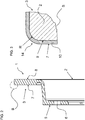
- FIG. 2 shows a section through the plane aa of the brake disc 1 from Fig. 1 , As can be seen, the exhibition 5 is facing the brake rim 3 of the base body 2.
- the brake ring 3 comprises two mutually parallel braking surfaces, ie friction surfaces 7, 8, that is to say a first friction surface 7 and a second friction surface 8
- FIG. 2 is a dash-dotted circle B located, wherein the area of the brake ring 3 within the circle B content of Fig. 3 is.
- Fig. 3 shows a detail of the brake ring 3 Fig. 2 Within the circle B.
- the enlargement of the brake ring 3 in the region of its first friction surface 7 can be seen that on a surface 9 of the base body 2 in this area an enamel coating 10 is applied.
- the enamel coating 10 also covers the outer peripheral surface here.
- the entire brake disc 1 may have an enamel coating 10. It is also conceivable if only the friction surfaces 7 and 8 have the enamel coating 10.
- the edge 14 is designed with a radius R, so that in this area a uniform enamel layer is applied.
- the radius R is approximately 3 times the layer thickness of the enamel coating 10. Larger radii are unproblematic, with smaller radii, the layer thickness in the region of the edge 14 may be distributed unevenly.
- the enamel coating 10 can also be applied at least partially on the brake disc, wherein only the friction surfaces 7 and 8 are provided with the enamel coating 10. But it is also possible, as mentioned, to provide the brake disc 1 completely with the enamel coating.
- the enamel coating can be applied by means of spraying devices or in a dipping bath.
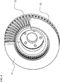
- FIG. 4 shows a brake disc 1, which has cover plates 11 and 12 between which ribs 13 are arranged, so that a ventilated brake disc 1 is formed.
- the ventilated brake disc can have the enamel coating 10 only at its friction surfaces 7 and 8. It is favorable, however, if the ventilated brake disc 1 is completely coated with enamel.
- the ventilated brake disc 1 can be placed in a dip, so that the inner surfaces the opposite cover plates 11 and 12 and the ribs 13 are coated with enamel.
- the brake disc 1 has different enamel coatings.
- the brake disc On the surfaces required to decelerate the vehicle, the brake disc may have an enamel coating, e.g. Signal effects in the form of bright even in the dark colors. It is quite within the meaning of the invention to provide the friction surfaces with corresponding signaling enamel coating.
- the brake disk should be at least partially preprocessed before applying the enamel coating 10. It is favorable to process the area of the brake disk 1, which is also to be coated.
- a drying and an annealing treatment is provided.
- a mechanical post-processing can be made.
Landscapes
- Engineering & Computer Science (AREA)
- General Engineering & Computer Science (AREA)
- Mechanical Engineering (AREA)
- Chemical & Material Sciences (AREA)
- Materials Engineering (AREA)
- Metallurgy (AREA)
- Organic Chemistry (AREA)
- Braking Arrangements (AREA)
Claims (16)
- Procédé de fabrication d'un disque de frein (1) pour un véhicule, selon lequel une couche de protection est agencée sur un corps de base (2) du disque de frein (1) ,
comprenant au moins les étapes suivantes :- le prétraitement au moins en zones du corps de base (2) présent à l'état d'ébauche ;- l'application au moins en zones d'un revêtement d'émail (10) sur le corps de base (2) ; et- le post-traitement du corps de base (2) revêtu au moins en zones, le revêtement d'émail (10) étant relié au matériau de base du corps de base (2) métallurgiquement par formation de phase. - Procédé selon la revendication 1, caractérisé en ce que le revêtement d'émail (10) est un mélange fondu qui comprend des oxydes formant du verre, ainsi que du borax, du feldspath, du quartz, un fluorure, de la soude, du nitrate de sodium et un agent opacifiant.
- Procédé selon la revendication 1 ou 2, caractérisé en ce que le revêtement d'émail (10) comprend des oxydes de cobalt, de manganèse et/ou de nickel.
- Procédé selon l'une quelconque des revendications précédentes, caractérisé en ce qu'au moins les surfaces de frottement (7, 8) du disque de frein sont prétraitées.
- Procédé selon l'une quelconque des revendications précédentes, caractérisé en ce que le prétraitement au moins en zones du disque de frein (1) est réalisé au moyen d'un procédé rotatif, de préférence au moyen d'un procédé rotatif de séchage.
- Procédé selon l'une quelconque des revendications précédentes, caractérisé en ce que la zone prétraitée présente une rugosité de 6 à 7 µm.
- Procédé selon l'une quelconque des revendications précédentes, caractérisé en ce que le revêtement d'émail (10) est appliqué par pulvérisation.
- Procédé selon l'une quelconque des revendications 1 à 6, caractérisé en ce que le revêtement d'émail (10) est appliqué dans un bain d'immersion.
- Procédé selon l'une quelconque des revendications précédentes, caractérisé en ce que le revêtement d'émail appliqué (10) est séché, le disque de frein (1) étant ensuite soumis à un traitement de recuit.
- Procédé selon l'une quelconque des revendications précédentes, caractérisé en ce que le revêtement d'émail appliqué (10) est soumis à un post-traitement mécanique.
- Disque de frein pour un véhicule, fabriqué par un procédé selon l'une quelconque des revendications précédentes, comprenant un corps de base (2) muni d'une couche de protection agencée au moins en zones, caractérisé en ce que le corps de base (2) comprend au moins en zones un revêtement d'émail (10).
- Disque de frein selon la revendication 11, caractérisé en ce que le revêtement d'émail (10) est agencé au moins sur les surfaces de frottement (7, 8).
- Disque de frein selon la revendication 11 ou 12, caractérisé en ce que le revêtement d'émail (10) est entièrement agencé sur le corps de base (2).
- Disque de frein selon l'une quelconque des revendications 11 à 13, caractérisé en ce que le revêtement d'émail (10) présente une épaisseur comprise entre 50 et 1 000 µm.
- Disque de frein selon l'une quelconque des revendications 11 à 14, caractérisé en ce que les bords munis d'un revêtement d'émail (10) du corps de base (2) présentent un rayon R qui est au moins 3 fois supérieur à l'épaisseur de couche du revêtement d'émail (10) dans la zone du rayon des bords.
- Disque de frein selon l'une quelconque des revendications 11 à 15, caractérisé en ce que le corps de base (2) est constitué de fonte grise.
Applications Claiming Priority (2)
| Application Number | Priority Date | Filing Date | Title |
|---|---|---|---|
| DE201310221737 DE102013221737A1 (de) | 2013-10-25 | 2013-10-25 | Verfahren zur Herstellung einer Bremsscheibe sowie Bremsscheibe |
| PCT/EP2014/072130 WO2015059011A2 (fr) | 2013-10-25 | 2014-10-15 | Procédé de fabrication d'un disque de frein et disque de frein |
Publications (2)
| Publication Number | Publication Date |
|---|---|
| EP3060824A2 EP3060824A2 (fr) | 2016-08-31 |
| EP3060824B1 true EP3060824B1 (fr) | 2017-08-23 |
Family
ID=51703182
Family Applications (1)
| Application Number | Title | Priority Date | Filing Date |
|---|---|---|---|
| EP14784085.4A Not-in-force EP3060824B1 (fr) | 2013-10-25 | 2014-10-15 | Procédé de fabrication d'un disque de frein et disque de frein |
Country Status (6)
| Country | Link |
|---|---|
| US (1) | US20160273601A1 (fr) |
| EP (1) | EP3060824B1 (fr) |
| CN (1) | CN105814333A (fr) |
| DE (1) | DE102013221737A1 (fr) |
| RU (1) | RU2646715C2 (fr) |
| WO (1) | WO2015059011A2 (fr) |
Families Citing this family (9)
| Publication number | Priority date | Publication date | Assignee | Title |
|---|---|---|---|---|
| US8893863B2 (en) | 2007-08-22 | 2014-11-25 | Tech M3, Inc. | Reduction of particulate emissions from vehicle braking systems |
| WO2009026458A1 (fr) * | 2007-08-22 | 2009-02-26 | Tech M3, Inc. | Disque de frein et procédé de fabrication de celui-ci |
| US20160348744A1 (en) * | 2014-02-05 | 2016-12-01 | Ford Global Technologies, Llc | Method for producing a brake disc and brake disc |
| DE102015212511B4 (de) | 2014-07-24 | 2019-06-06 | Ford Global Technologies, Llc | Verfahren zur Herstellung einer Bremsscheibe sowie Bremsscheibe |
| RU2674899C1 (ru) * | 2016-07-12 | 2018-12-13 | Владимир Владимирович Шаповалов | Способ повышения эффективности фрикционных систем |
| RO132861B1 (ro) * | 2017-04-12 | 2021-09-30 | Dumitru Meseşan | Metodă de comba- tere a poluării cauzate de dispozitivele de frânare |
| US10962070B2 (en) * | 2017-09-21 | 2021-03-30 | Robert Bosch Gmbh | Brake disk and method for producing a brake disk |
| DE102018200321A1 (de) * | 2018-01-11 | 2019-07-11 | Robert Bosch Gmbh | Verfahren zum Herstellen einer Bremsscheibe, Bremsscheibe |
| CN112119236B (zh) | 2018-05-16 | 2023-03-31 | 天纳克公司 | 制动垫块背衬板 |
Family Cites Families (18)
| Publication number | Priority date | Publication date | Assignee | Title |
|---|---|---|---|---|
| GB634478A (en) * | 1941-06-19 | 1950-03-22 | Poor & Co | Improvement in enamel coatings for ferrous metals |
| US3061482A (en) * | 1959-09-16 | 1962-10-30 | Nicholas J Grant | Ceramic coated metal bodies |
| US3390750A (en) | 1966-10-25 | 1968-07-02 | Borg Warner | Friction element having a layer of porous sintered metal fibers |
| US3844800A (en) * | 1969-02-14 | 1974-10-29 | Bendix Corp | Friction material |
| US4394064A (en) * | 1981-06-30 | 1983-07-19 | Ppg Industries, Inc. | Durable ceramic enamel spandrels |
| DE323349T1 (de) * | 1987-12-30 | 1990-02-08 | Seb S.A., Selongey, Cote D'or, Fr | Mit glasperlen gefuellte email-beschichtung fuer kochgeraete und so bekleidete kochgeraete. |
| DE4122763A1 (de) * | 1991-07-10 | 1993-01-14 | Email Bruegge Nv | Emailschlicker, verfahren zur emaillierung von aluminiumbeschichtetem stahlblech sowie emailliertes stahlblech |
| CA2099397A1 (fr) * | 1992-07-07 | 1994-01-08 | Gerald S. Cole | Rotor de frein a disque composite et methode de fabrication correspondante |
| US5339931A (en) * | 1993-05-07 | 1994-08-23 | Allied-Signal Inc. | Porous copper powder modified friction material |
| FR2718130B1 (fr) * | 1994-04-05 | 1996-06-21 | Europ Propulsion | Procédé pour l'application d'une protection anti-oxydation sur des disques de frein en matériau composite contenant du carbone. |
| DE10056161A1 (de) * | 2000-11-13 | 2002-05-29 | Knorr Bremse Systeme | Bremsscheibe und Verfahren zu deren Herstellung |
| DE102005008569A1 (de) * | 2005-02-24 | 2006-10-05 | FNE Forschungsinstitut für Nichteisen-Metalle Freiberg GmbH | Reibelement und Verfahren zu dessen Herstellung |
| DE102005022264A1 (de) * | 2005-05-10 | 2006-11-16 | Fachhochschule Münster | Flüssigauftragbare Einbrennbeschichtung |
| ITMI20060314A1 (it) | 2006-02-21 | 2007-08-22 | Mako Shark Srl | Disco freno |
| DE102006050985A1 (de) * | 2006-10-26 | 2008-04-30 | Fachhochschule Münster | Flüssigauftragbare verschleißbeständige Einbrennbeschichtung |
| DE102009003161A1 (de) * | 2009-05-15 | 2010-11-18 | Ford Global Technologies, LLC, Dearborn | Beschichtete Leichtmetallscheibe und Verfahren zu deren Herstellung |
| DE102010049797A1 (de) | 2010-10-27 | 2012-05-03 | Daimler Ag | Radnabe und Bremsscheibe |
| DE102011012320B4 (de) * | 2011-02-25 | 2015-05-28 | Daimler Ag | Verfahren zur Herstellung einer Bremsscheibe |
-
2013
- 2013-10-25 DE DE201310221737 patent/DE102013221737A1/de not_active Withdrawn
-
2014
- 2014-10-15 CN CN201480058234.XA patent/CN105814333A/zh active Pending
- 2014-10-15 US US15/031,895 patent/US20160273601A1/en not_active Abandoned
- 2014-10-15 WO PCT/EP2014/072130 patent/WO2015059011A2/fr active Application Filing
- 2014-10-15 EP EP14784085.4A patent/EP3060824B1/fr not_active Not-in-force
- 2014-10-15 RU RU2016119946A patent/RU2646715C2/ru not_active IP Right Cessation
Non-Patent Citations (1)
| Title |
|---|
| None * |
Also Published As
| Publication number | Publication date |
|---|---|
| RU2646715C2 (ru) | 2018-03-06 |
| EP3060824A2 (fr) | 2016-08-31 |
| DE102013221737A1 (de) | 2015-04-30 |
| WO2015059011A2 (fr) | 2015-04-30 |
| CN105814333A (zh) | 2016-07-27 |
| WO2015059011A3 (fr) | 2015-06-18 |
| US20160273601A1 (en) | 2016-09-22 |
| RU2016119946A (ru) | 2017-11-27 |
Similar Documents
| Publication | Publication Date | Title |
|---|---|---|
| EP3102844B1 (fr) | Procédé de production d'un disque de frein, et disque de frein | |
| EP3060824B1 (fr) | Procédé de fabrication d'un disque de frein et disque de frein | |
| DE102014205666A1 (de) | Verfahren zur Herstellung einer Bremsscheibe sowie Bremsscheibe | |
| EP3026288B1 (fr) | Procédé de fabrication d'un disque de frein et disque de frein | |
| DE102019212844A1 (de) | Bremsscheibe und Verfahren zum Herstellen einer Bremsscheibe | |
| EP4085158B1 (fr) | Disque de frein doté d'une protection contre l'usure et la corrosion et son procédé de production | |
| EP3620545B1 (fr) | Disque de frein et procédé de fabrication d'un disque de frein | |
| WO2010130529A1 (fr) | Disque en alliage léger revêtu | |
| DE102015204813B4 (de) | Verfahren zur Herstellung einer Bremsscheibe sowie Bremsscheibe | |
| DE102019210088A1 (de) | Bremsscheibe und Verfahren zum Herstellen einer Bremsscheibe | |
| EP3620546A2 (fr) | Disque de frein et procédé de fabrication d'un disque de frein | |
| EP3022338B1 (fr) | Procédé pour la fabrication d'un disque de frein ainsi que disque de frein | |
| DE102010048075A1 (de) | Bremsscheibe und Verfahren zu deren Herstellung | |
| DE102015200054A1 (de) | Verfahren zur Herstellung einer Bremsscheibe sowie Bremsscheibe | |
| DE102008036996B4 (de) | Gleit- und/oder Gegenring einer Laufwerkdichtung | |
| DE102014221377A1 (de) | Verfahren zur Herstellung einer Bremsscheibe sowie Bremsscheibe | |
| WO2019219551A1 (fr) | Corps de freinage et procédé de fabrication associé | |
| EP4278109A1 (fr) | Procédé de fabrication d'un élément de freinage et élément de freinage | |
| EP4278108A1 (fr) | Procédé de production d'un élément de freinage et élément de freinage | |
| EP2213901A1 (fr) | Disque de frein pour frein à disque ainsi que procédé de fabrication d'un disque de frein |
Legal Events
| Date | Code | Title | Description |
|---|---|---|---|
| PUAI | Public reference made under article 153(3) epc to a published international application that has entered the european phase |
Free format text: ORIGINAL CODE: 0009012 |
|
| 17P | Request for examination filed |
Effective date: 20160525 |
|
| AK | Designated contracting states |
Kind code of ref document: A2 Designated state(s): AL AT BE BG CH CY CZ DE DK EE ES FI FR GB GR HR HU IE IS IT LI LT LU LV MC MK MT NL NO PL PT RO RS SE SI SK SM TR |
|
| AX | Request for extension of the european patent |
Extension state: BA ME |
|
| DAX | Request for extension of the european patent (deleted) | ||
| GRAP | Despatch of communication of intention to grant a patent |
Free format text: ORIGINAL CODE: EPIDOSNIGR1 |
|
| INTG | Intention to grant announced |
Effective date: 20170530 |
|
| GRAS | Grant fee paid |
Free format text: ORIGINAL CODE: EPIDOSNIGR3 |
|
| GRAA | (expected) grant |
Free format text: ORIGINAL CODE: 0009210 |
|
| AK | Designated contracting states |
Kind code of ref document: B1 Designated state(s): AL AT BE BG CH CY CZ DE DK EE ES FI FR GB GR HR HU IE IS IT LI LT LU LV MC MK MT NL NO PL PT RO RS SE SI SK SM TR |
|
| REG | Reference to a national code |
Ref country code: GB Ref legal event code: FG4D Free format text: NOT ENGLISH |
|
| REG | Reference to a national code |
Ref country code: CH Ref legal event code: EP |
|
| REG | Reference to a national code |
Ref country code: AT Ref legal event code: REF Ref document number: 921686 Country of ref document: AT Kind code of ref document: T Effective date: 20170915 |
|
| REG | Reference to a national code |
Ref country code: IE Ref legal event code: FG4D Free format text: LANGUAGE OF EP DOCUMENT: GERMAN |
|
| REG | Reference to a national code |
Ref country code: FR Ref legal event code: PLFP Year of fee payment: 4 |
|
| REG | Reference to a national code |
Ref country code: DE Ref legal event code: R096 Ref document number: 502014005185 Country of ref document: DE |
|
| REG | Reference to a national code |
Ref country code: NL Ref legal event code: MP Effective date: 20170823 |
|
| REG | Reference to a national code |
Ref country code: LT Ref legal event code: MG4D |
|
| PG25 | Lapsed in a contracting state [announced via postgrant information from national office to epo] |
Ref country code: SE Free format text: LAPSE BECAUSE OF FAILURE TO SUBMIT A TRANSLATION OF THE DESCRIPTION OR TO PAY THE FEE WITHIN THE PRESCRIBED TIME-LIMIT Effective date: 20170823 Ref country code: NL Free format text: LAPSE BECAUSE OF FAILURE TO SUBMIT A TRANSLATION OF THE DESCRIPTION OR TO PAY THE FEE WITHIN THE PRESCRIBED TIME-LIMIT Effective date: 20170823 Ref country code: LT Free format text: LAPSE BECAUSE OF FAILURE TO SUBMIT A TRANSLATION OF THE DESCRIPTION OR TO PAY THE FEE WITHIN THE PRESCRIBED TIME-LIMIT Effective date: 20170823 Ref country code: FI Free format text: LAPSE BECAUSE OF FAILURE TO SUBMIT A TRANSLATION OF THE DESCRIPTION OR TO PAY THE FEE WITHIN THE PRESCRIBED TIME-LIMIT Effective date: 20170823 Ref country code: NO Free format text: LAPSE BECAUSE OF FAILURE TO SUBMIT A TRANSLATION OF THE DESCRIPTION OR TO PAY THE FEE WITHIN THE PRESCRIBED TIME-LIMIT Effective date: 20171123 Ref country code: HR Free format text: LAPSE BECAUSE OF FAILURE TO SUBMIT A TRANSLATION OF THE DESCRIPTION OR TO PAY THE FEE WITHIN THE PRESCRIBED TIME-LIMIT Effective date: 20170823 |
|
| PG25 | Lapsed in a contracting state [announced via postgrant information from national office to epo] |
Ref country code: GR Free format text: LAPSE BECAUSE OF FAILURE TO SUBMIT A TRANSLATION OF THE DESCRIPTION OR TO PAY THE FEE WITHIN THE PRESCRIBED TIME-LIMIT Effective date: 20171124 Ref country code: BG Free format text: LAPSE BECAUSE OF FAILURE TO SUBMIT A TRANSLATION OF THE DESCRIPTION OR TO PAY THE FEE WITHIN THE PRESCRIBED TIME-LIMIT Effective date: 20171123 Ref country code: PL Free format text: LAPSE BECAUSE OF FAILURE TO SUBMIT A TRANSLATION OF THE DESCRIPTION OR TO PAY THE FEE WITHIN THE PRESCRIBED TIME-LIMIT Effective date: 20170823 Ref country code: ES Free format text: LAPSE BECAUSE OF FAILURE TO SUBMIT A TRANSLATION OF THE DESCRIPTION OR TO PAY THE FEE WITHIN THE PRESCRIBED TIME-LIMIT Effective date: 20170823 Ref country code: IS Free format text: LAPSE BECAUSE OF FAILURE TO SUBMIT A TRANSLATION OF THE DESCRIPTION OR TO PAY THE FEE WITHIN THE PRESCRIBED TIME-LIMIT Effective date: 20171223 Ref country code: LV Free format text: LAPSE BECAUSE OF FAILURE TO SUBMIT A TRANSLATION OF THE DESCRIPTION OR TO PAY THE FEE WITHIN THE PRESCRIBED TIME-LIMIT Effective date: 20170823 Ref country code: RS Free format text: LAPSE BECAUSE OF FAILURE TO SUBMIT A TRANSLATION OF THE DESCRIPTION OR TO PAY THE FEE WITHIN THE PRESCRIBED TIME-LIMIT Effective date: 20170823 |
|
| PG25 | Lapsed in a contracting state [announced via postgrant information from national office to epo] |
Ref country code: DK Free format text: LAPSE BECAUSE OF FAILURE TO SUBMIT A TRANSLATION OF THE DESCRIPTION OR TO PAY THE FEE WITHIN THE PRESCRIBED TIME-LIMIT Effective date: 20170823 Ref country code: CZ Free format text: LAPSE BECAUSE OF FAILURE TO SUBMIT A TRANSLATION OF THE DESCRIPTION OR TO PAY THE FEE WITHIN THE PRESCRIBED TIME-LIMIT Effective date: 20170823 Ref country code: RO Free format text: LAPSE BECAUSE OF FAILURE TO SUBMIT A TRANSLATION OF THE DESCRIPTION OR TO PAY THE FEE WITHIN THE PRESCRIBED TIME-LIMIT Effective date: 20170823 |
|
| REG | Reference to a national code |
Ref country code: DE Ref legal event code: R097 Ref document number: 502014005185 Country of ref document: DE |
|
| PG25 | Lapsed in a contracting state [announced via postgrant information from national office to epo] |
Ref country code: SM Free format text: LAPSE BECAUSE OF FAILURE TO SUBMIT A TRANSLATION OF THE DESCRIPTION OR TO PAY THE FEE WITHIN THE PRESCRIBED TIME-LIMIT Effective date: 20170823 Ref country code: MC Free format text: LAPSE BECAUSE OF FAILURE TO SUBMIT A TRANSLATION OF THE DESCRIPTION OR TO PAY THE FEE WITHIN THE PRESCRIBED TIME-LIMIT Effective date: 20170823 Ref country code: SK Free format text: LAPSE BECAUSE OF FAILURE TO SUBMIT A TRANSLATION OF THE DESCRIPTION OR TO PAY THE FEE WITHIN THE PRESCRIBED TIME-LIMIT Effective date: 20170823 Ref country code: EE Free format text: LAPSE BECAUSE OF FAILURE TO SUBMIT A TRANSLATION OF THE DESCRIPTION OR TO PAY THE FEE WITHIN THE PRESCRIBED TIME-LIMIT Effective date: 20170823 Ref country code: IT Free format text: LAPSE BECAUSE OF FAILURE TO SUBMIT A TRANSLATION OF THE DESCRIPTION OR TO PAY THE FEE WITHIN THE PRESCRIBED TIME-LIMIT Effective date: 20170823 |
|
| REG | Reference to a national code |
Ref country code: CH Ref legal event code: PL |
|
| PLBE | No opposition filed within time limit |
Free format text: ORIGINAL CODE: 0009261 |
|
| STAA | Information on the status of an ep patent application or granted ep patent |
Free format text: STATUS: NO OPPOSITION FILED WITHIN TIME LIMIT |
|
| REG | Reference to a national code |
Ref country code: IE Ref legal event code: MM4A |
|
| PG25 | Lapsed in a contracting state [announced via postgrant information from national office to epo] |
Ref country code: LU Free format text: LAPSE BECAUSE OF NON-PAYMENT OF DUE FEES Effective date: 20171015 Ref country code: CH Free format text: LAPSE BECAUSE OF NON-PAYMENT OF DUE FEES Effective date: 20171031 Ref country code: LI Free format text: LAPSE BECAUSE OF NON-PAYMENT OF DUE FEES Effective date: 20171031 |
|
| 26N | No opposition filed |
Effective date: 20180524 |
|
| REG | Reference to a national code |
Ref country code: BE Ref legal event code: MM Effective date: 20171031 |
|
| PG25 | Lapsed in a contracting state [announced via postgrant information from national office to epo] |
Ref country code: BE Free format text: LAPSE BECAUSE OF NON-PAYMENT OF DUE FEES Effective date: 20171031 Ref country code: SI Free format text: LAPSE BECAUSE OF FAILURE TO SUBMIT A TRANSLATION OF THE DESCRIPTION OR TO PAY THE FEE WITHIN THE PRESCRIBED TIME-LIMIT Effective date: 20170823 |
|
| REG | Reference to a national code |
Ref country code: FR Ref legal event code: PLFP Year of fee payment: 5 |
|
| PG25 | Lapsed in a contracting state [announced via postgrant information from national office to epo] |
Ref country code: MT Free format text: LAPSE BECAUSE OF FAILURE TO SUBMIT A TRANSLATION OF THE DESCRIPTION OR TO PAY THE FEE WITHIN THE PRESCRIBED TIME-LIMIT Effective date: 20170823 |
|
| PG25 | Lapsed in a contracting state [announced via postgrant information from national office to epo] |
Ref country code: IE Free format text: LAPSE BECAUSE OF NON-PAYMENT OF DUE FEES Effective date: 20171015 |
|
| PGFP | Annual fee paid to national office [announced via postgrant information from national office to epo] |
Ref country code: FR Payment date: 20180920 Year of fee payment: 5 |
|
| PGFP | Annual fee paid to national office [announced via postgrant information from national office to epo] |
Ref country code: GB Payment date: 20180926 Year of fee payment: 5 |
|
| PGFP | Annual fee paid to national office [announced via postgrant information from national office to epo] |
Ref country code: DE Payment date: 20180917 Year of fee payment: 5 |
|
| PG25 | Lapsed in a contracting state [announced via postgrant information from national office to epo] |
Ref country code: HU Free format text: LAPSE BECAUSE OF FAILURE TO SUBMIT A TRANSLATION OF THE DESCRIPTION OR TO PAY THE FEE WITHIN THE PRESCRIBED TIME-LIMIT; INVALID AB INITIO Effective date: 20141015 |
|
| PG25 | Lapsed in a contracting state [announced via postgrant information from national office to epo] |
Ref country code: CY Free format text: LAPSE BECAUSE OF FAILURE TO SUBMIT A TRANSLATION OF THE DESCRIPTION OR TO PAY THE FEE WITHIN THE PRESCRIBED TIME-LIMIT Effective date: 20170823 |
|
| PG25 | Lapsed in a contracting state [announced via postgrant information from national office to epo] |
Ref country code: MK Free format text: LAPSE BECAUSE OF FAILURE TO SUBMIT A TRANSLATION OF THE DESCRIPTION OR TO PAY THE FEE WITHIN THE PRESCRIBED TIME-LIMIT Effective date: 20170823 |
|
| PG25 | Lapsed in a contracting state [announced via postgrant information from national office to epo] |
Ref country code: TR Free format text: LAPSE BECAUSE OF FAILURE TO SUBMIT A TRANSLATION OF THE DESCRIPTION OR TO PAY THE FEE WITHIN THE PRESCRIBED TIME-LIMIT Effective date: 20170823 |
|
| REG | Reference to a national code |
Ref country code: DE Ref legal event code: R119 Ref document number: 502014005185 Country of ref document: DE |
|
| PG25 | Lapsed in a contracting state [announced via postgrant information from national office to epo] |
Ref country code: PT Free format text: LAPSE BECAUSE OF FAILURE TO SUBMIT A TRANSLATION OF THE DESCRIPTION OR TO PAY THE FEE WITHIN THE PRESCRIBED TIME-LIMIT Effective date: 20170823 |
|
| PG25 | Lapsed in a contracting state [announced via postgrant information from national office to epo] |
Ref country code: DE Free format text: LAPSE BECAUSE OF NON-PAYMENT OF DUE FEES Effective date: 20200501 Ref country code: AL Free format text: LAPSE BECAUSE OF FAILURE TO SUBMIT A TRANSLATION OF THE DESCRIPTION OR TO PAY THE FEE WITHIN THE PRESCRIBED TIME-LIMIT Effective date: 20170823 |
|
| GBPC | Gb: european patent ceased through non-payment of renewal fee |
Effective date: 20191015 |
|
| PG25 | Lapsed in a contracting state [announced via postgrant information from national office to epo] |
Ref country code: GB Free format text: LAPSE BECAUSE OF NON-PAYMENT OF DUE FEES Effective date: 20191015 Ref country code: FR Free format text: LAPSE BECAUSE OF NON-PAYMENT OF DUE FEES Effective date: 20191031 |
|
| REG | Reference to a national code |
Ref country code: AT Ref legal event code: MM01 Ref document number: 921686 Country of ref document: AT Kind code of ref document: T Effective date: 20191015 |
|
| PG25 | Lapsed in a contracting state [announced via postgrant information from national office to epo] |
Ref country code: AT Free format text: LAPSE BECAUSE OF NON-PAYMENT OF DUE FEES Effective date: 20191015 |