EP3059801B1 - Structure d'alimentation en électricité, plaque en résine pour fenêtre dotée de ladite structure et procédé de production de plaque en résine pour fenêtre dotée de structure d'alimentation en électricité - Google Patents
Structure d'alimentation en électricité, plaque en résine pour fenêtre dotée de ladite structure et procédé de production de plaque en résine pour fenêtre dotée de structure d'alimentation en électricité Download PDFInfo
- Publication number
- EP3059801B1 EP3059801B1 EP14853433.2A EP14853433A EP3059801B1 EP 3059801 B1 EP3059801 B1 EP 3059801B1 EP 14853433 A EP14853433 A EP 14853433A EP 3059801 B1 EP3059801 B1 EP 3059801B1
- Authority
- EP
- European Patent Office
- Prior art keywords
- resin
- power feeding
- electrical conductive
- conductive portion
- plate body
- Prior art date
- Legal status (The legal status is an assumption and is not a legal conclusion. Google has not performed a legal analysis and makes no representation as to the accuracy of the status listed.)
- Active
Links
- 229920005989 resin Polymers 0.000 title claims description 332
- 239000011347 resin Substances 0.000 title claims description 332
- 238000004519 manufacturing process Methods 0.000 title claims description 14
- 238000000034 method Methods 0.000 title description 2
- 239000004020 conductor Substances 0.000 claims description 104
- 238000001746 injection moulding Methods 0.000 claims description 25
- 229910052751 metal Inorganic materials 0.000 claims description 23
- 239000002184 metal Substances 0.000 claims description 23
- 239000000463 material Substances 0.000 claims description 17
- 238000002347 injection Methods 0.000 claims description 11
- 239000007924 injection Substances 0.000 claims description 11
- 238000003466 welding Methods 0.000 claims description 6
- 238000002844 melting Methods 0.000 claims description 5
- 230000008018 melting Effects 0.000 claims description 5
- 229920001169 thermoplastic Polymers 0.000 claims description 3
- 239000004416 thermosoftening plastic Substances 0.000 claims description 3
- 239000010410 layer Substances 0.000 description 20
- 239000000853 adhesive Substances 0.000 description 15
- 230000001070 adhesive effect Effects 0.000 description 9
- 239000011888 foil Substances 0.000 description 7
- PXHVJJICTQNCMI-UHFFFAOYSA-N Nickel Chemical compound [Ni] PXHVJJICTQNCMI-UHFFFAOYSA-N 0.000 description 4
- BQCADISMDOOEFD-UHFFFAOYSA-N Silver Chemical compound [Ag] BQCADISMDOOEFD-UHFFFAOYSA-N 0.000 description 4
- 229910052709 silver Inorganic materials 0.000 description 4
- 239000004332 silver Substances 0.000 description 4
- RYGMFSIKBFXOCR-UHFFFAOYSA-N Copper Chemical compound [Cu] RYGMFSIKBFXOCR-UHFFFAOYSA-N 0.000 description 3
- 238000007796 conventional method Methods 0.000 description 3
- 229910052802 copper Inorganic materials 0.000 description 3
- 239000010949 copper Substances 0.000 description 3
- PCHJSUWPFVWCPO-UHFFFAOYSA-N gold Chemical compound [Au] PCHJSUWPFVWCPO-UHFFFAOYSA-N 0.000 description 3
- 229910052737 gold Inorganic materials 0.000 description 3
- 239000010931 gold Substances 0.000 description 3
- 238000010438 heat treatment Methods 0.000 description 3
- 229920000515 polycarbonate Polymers 0.000 description 3
- 239000004417 polycarbonate Substances 0.000 description 3
- 238000007639 printing Methods 0.000 description 3
- 238000007650 screen-printing Methods 0.000 description 3
- 229910000679 solder Inorganic materials 0.000 description 3
- OKTJSMMVPCPJKN-UHFFFAOYSA-N Carbon Chemical compound [C] OKTJSMMVPCPJKN-UHFFFAOYSA-N 0.000 description 2
- 229910052782 aluminium Inorganic materials 0.000 description 2
- XAGFODPZIPBFFR-UHFFFAOYSA-N aluminium Chemical compound [Al] XAGFODPZIPBFFR-UHFFFAOYSA-N 0.000 description 2
- 229910052799 carbon Inorganic materials 0.000 description 2
- 230000001419 dependent effect Effects 0.000 description 2
- 230000000694 effects Effects 0.000 description 2
- 239000005357 flat glass Substances 0.000 description 2
- 238000012986 modification Methods 0.000 description 2
- 230000004048 modification Effects 0.000 description 2
- 229910052759 nickel Inorganic materials 0.000 description 2
- 229920006289 polycarbonate film Polymers 0.000 description 2
- 238000010079 rubber tapping Methods 0.000 description 2
- 239000004925 Acrylic resin Substances 0.000 description 1
- 239000004642 Polyimide Substances 0.000 description 1
- 239000012790 adhesive layer Substances 0.000 description 1
- 239000002390 adhesive tape Substances 0.000 description 1
- 230000008878 coupling Effects 0.000 description 1
- 238000010168 coupling process Methods 0.000 description 1
- 238000005859 coupling reaction Methods 0.000 description 1
- 238000001035 drying Methods 0.000 description 1
- 238000001704 evaporation Methods 0.000 description 1
- 239000011521 glass Substances 0.000 description 1
- 238000000465 moulding Methods 0.000 description 1
- 230000010355 oscillation Effects 0.000 description 1
- 239000003973 paint Substances 0.000 description 1
- 230000000149 penetrating effect Effects 0.000 description 1
- 229920000728 polyester Polymers 0.000 description 1
- 229920001721 polyimide Polymers 0.000 description 1
- 229920000098 polyolefin Polymers 0.000 description 1
- 229920000915 polyvinyl chloride Polymers 0.000 description 1
- 239000004800 polyvinyl chloride Substances 0.000 description 1
- 239000002904 solvent Substances 0.000 description 1
- 229920005992 thermoplastic resin Polymers 0.000 description 1
- 230000037303 wrinkles Effects 0.000 description 1
Images


Classifications
-
- B—PERFORMING OPERATIONS; TRANSPORTING
- B60—VEHICLES IN GENERAL
- B60L—PROPULSION OF ELECTRICALLY-PROPELLED VEHICLES; SUPPLYING ELECTRIC POWER FOR AUXILIARY EQUIPMENT OF ELECTRICALLY-PROPELLED VEHICLES; ELECTRODYNAMIC BRAKE SYSTEMS FOR VEHICLES IN GENERAL; MAGNETIC SUSPENSION OR LEVITATION FOR VEHICLES; MONITORING OPERATING VARIABLES OF ELECTRICALLY-PROPELLED VEHICLES; ELECTRIC SAFETY DEVICES FOR ELECTRICALLY-PROPELLED VEHICLES
- B60L1/00—Supplying electric power to auxiliary equipment of vehicles
- B60L1/02—Supplying electric power to auxiliary equipment of vehicles to electric heating circuits
-
- B—PERFORMING OPERATIONS; TRANSPORTING
- B29—WORKING OF PLASTICS; WORKING OF SUBSTANCES IN A PLASTIC STATE IN GENERAL
- B29C—SHAPING OR JOINING OF PLASTICS; SHAPING OF MATERIAL IN A PLASTIC STATE, NOT OTHERWISE PROVIDED FOR; AFTER-TREATMENT OF THE SHAPED PRODUCTS, e.g. REPAIRING
- B29C45/00—Injection moulding, i.e. forcing the required volume of moulding material through a nozzle into a closed mould; Apparatus therefor
- B29C45/14—Injection moulding, i.e. forcing the required volume of moulding material through a nozzle into a closed mould; Apparatus therefor incorporating preformed parts or layers, e.g. injection moulding around inserts or for coating articles
- B29C45/14639—Injection moulding, i.e. forcing the required volume of moulding material through a nozzle into a closed mould; Apparatus therefor incorporating preformed parts or layers, e.g. injection moulding around inserts or for coating articles for obtaining an insulating effect, e.g. for electrical components
-
- B—PERFORMING OPERATIONS; TRANSPORTING
- B60—VEHICLES IN GENERAL
- B60J—WINDOWS, WINDSCREENS, NON-FIXED ROOFS, DOORS, OR SIMILAR DEVICES FOR VEHICLES; REMOVABLE EXTERNAL PROTECTIVE COVERINGS SPECIALLY ADAPTED FOR VEHICLES
- B60J1/00—Windows; Windscreens; Accessories therefor
- B60J1/002—Windows; Windscreens; Accessories therefor with means for clear vision, e.g. anti-frost or defog panes, rain shields
-
- B—PERFORMING OPERATIONS; TRANSPORTING
- B60—VEHICLES IN GENERAL
- B60J—WINDOWS, WINDSCREENS, NON-FIXED ROOFS, DOORS, OR SIMILAR DEVICES FOR VEHICLES; REMOVABLE EXTERNAL PROTECTIVE COVERINGS SPECIALLY ADAPTED FOR VEHICLES
- B60J1/00—Windows; Windscreens; Accessories therefor
- B60J1/08—Windows; Windscreens; Accessories therefor arranged at vehicle sides
-
- B—PERFORMING OPERATIONS; TRANSPORTING
- B60—VEHICLES IN GENERAL
- B60J—WINDOWS, WINDSCREENS, NON-FIXED ROOFS, DOORS, OR SIMILAR DEVICES FOR VEHICLES; REMOVABLE EXTERNAL PROTECTIVE COVERINGS SPECIALLY ADAPTED FOR VEHICLES
- B60J1/00—Windows; Windscreens; Accessories therefor
- B60J1/18—Windows; Windscreens; Accessories therefor arranged at the vehicle rear
-
- B—PERFORMING OPERATIONS; TRANSPORTING
- B60—VEHICLES IN GENERAL
- B60J—WINDOWS, WINDSCREENS, NON-FIXED ROOFS, DOORS, OR SIMILAR DEVICES FOR VEHICLES; REMOVABLE EXTERNAL PROTECTIVE COVERINGS SPECIALLY ADAPTED FOR VEHICLES
- B60J7/00—Non-fixed roofs; Roofs with movable panels, e.g. rotary sunroofs
- B60J7/02—Non-fixed roofs; Roofs with movable panels, e.g. rotary sunroofs of sliding type, e.g. comprising guide shoes
- B60J7/04—Non-fixed roofs; Roofs with movable panels, e.g. rotary sunroofs of sliding type, e.g. comprising guide shoes with rigid plate-like element or elements, e.g. open roofs with harmonica-type folding rigid panels
- B60J7/043—Sunroofs e.g. sliding above the roof
-
- H—ELECTRICITY
- H01—ELECTRIC ELEMENTS
- H01Q—ANTENNAS, i.e. RADIO AERIALS
- H01Q1/00—Details of, or arrangements associated with, antennas
- H01Q1/12—Supports; Mounting means
- H01Q1/1271—Supports; Mounting means for mounting on windscreens
-
- B—PERFORMING OPERATIONS; TRANSPORTING
- B29—WORKING OF PLASTICS; WORKING OF SUBSTANCES IN A PLASTIC STATE IN GENERAL
- B29K—INDEXING SCHEME ASSOCIATED WITH SUBCLASSES B29B, B29C OR B29D, RELATING TO MOULDING MATERIALS OR TO MATERIALS FOR MOULDS, REINFORCEMENTS, FILLERS OR PREFORMED PARTS, e.g. INSERTS
- B29K2069/00—Use of PC, i.e. polycarbonates or derivatives thereof, as moulding material
-
- B—PERFORMING OPERATIONS; TRANSPORTING
- B29—WORKING OF PLASTICS; WORKING OF SUBSTANCES IN A PLASTIC STATE IN GENERAL
- B29K—INDEXING SCHEME ASSOCIATED WITH SUBCLASSES B29B, B29C OR B29D, RELATING TO MOULDING MATERIALS OR TO MATERIALS FOR MOULDS, REINFORCEMENTS, FILLERS OR PREFORMED PARTS, e.g. INSERTS
- B29K2701/00—Use of unspecified macromolecular compounds for preformed parts, e.g. for inserts
- B29K2701/12—Thermoplastic materials
-
- B—PERFORMING OPERATIONS; TRANSPORTING
- B29—WORKING OF PLASTICS; WORKING OF SUBSTANCES IN A PLASTIC STATE IN GENERAL
- B29K—INDEXING SCHEME ASSOCIATED WITH SUBCLASSES B29B, B29C OR B29D, RELATING TO MOULDING MATERIALS OR TO MATERIALS FOR MOULDS, REINFORCEMENTS, FILLERS OR PREFORMED PARTS, e.g. INSERTS
- B29K2705/00—Use of metals, their alloys or their compounds, for preformed parts, e.g. for inserts
- B29K2705/08—Transition metals
- B29K2705/10—Copper
-
- B—PERFORMING OPERATIONS; TRANSPORTING
- B29—WORKING OF PLASTICS; WORKING OF SUBSTANCES IN A PLASTIC STATE IN GENERAL
- B29K—INDEXING SCHEME ASSOCIATED WITH SUBCLASSES B29B, B29C OR B29D, RELATING TO MOULDING MATERIALS OR TO MATERIALS FOR MOULDS, REINFORCEMENTS, FILLERS OR PREFORMED PARTS, e.g. INSERTS
- B29K2705/00—Use of metals, their alloys or their compounds, for preformed parts, e.g. for inserts
- B29K2705/08—Transition metals
- B29K2705/14—Noble metals, e.g. silver, gold or platinum
-
- B—PERFORMING OPERATIONS; TRANSPORTING
- B29—WORKING OF PLASTICS; WORKING OF SUBSTANCES IN A PLASTIC STATE IN GENERAL
- B29K—INDEXING SCHEME ASSOCIATED WITH SUBCLASSES B29B, B29C OR B29D, RELATING TO MOULDING MATERIALS OR TO MATERIALS FOR MOULDS, REINFORCEMENTS, FILLERS OR PREFORMED PARTS, e.g. INSERTS
- B29K2995/00—Properties of moulding materials, reinforcements, fillers, preformed parts or moulds
- B29K2995/0018—Properties of moulding materials, reinforcements, fillers, preformed parts or moulds having particular optical properties, e.g. fluorescent or phosphorescent
- B29K2995/0026—Transparent
-
- B—PERFORMING OPERATIONS; TRANSPORTING
- B29—WORKING OF PLASTICS; WORKING OF SUBSTANCES IN A PLASTIC STATE IN GENERAL
- B29L—INDEXING SCHEME ASSOCIATED WITH SUBCLASS B29C, RELATING TO PARTICULAR ARTICLES
- B29L2031/00—Other particular articles
- B29L2031/30—Vehicles, e.g. ships or aircraft, or body parts thereof
- B29L2031/3052—Windscreens
-
- B—PERFORMING OPERATIONS; TRANSPORTING
- B60—VEHICLES IN GENERAL
- B60Y—INDEXING SCHEME RELATING TO ASPECTS CROSS-CUTTING VEHICLE TECHNOLOGY
- B60Y2410/00—Constructional features of vehicle sub-units
- B60Y2410/12—Production or manufacturing of vehicle parts
Definitions
- the present invention relates to a power feeding structure and a resin plate body for window including the power feeding structure. Further, the present invention relates to a method of manufacturing a resin plate body for window including a power feeding structure.
- the resin plate body for window is started to be used instead of a window glass, in particular, for vehicles.
- the resin plate body for window it is difficult to print an electrical conductor such as a glass antenna or the like at a surface of the resin plate body by printing a silver paste and baking it, similarly as the window glass.
- the resin plate body for window including an electrical conductor is configured by interposing a printed electrical conductor formed at a surface of a resin film between the resin film and a resin panel. In such a case, as the printed electrical conductor is sealed inside the resin plate body for window, it is difficult to feed electrical power to the printed electrical conductor.
- Patent Document 1 discloses a metal foil as such an electrical conductive portion.
- Patent Document 2 discloses a connector for a flat multilayer element.
- the present invention is made in light of the above problems, and provides a power feeding structure, a resin plate body for window including the power feeding structure and a method of manufacturing a resin plate body for window including a power feeding structure in which stable bonding of an electrical conductive portion that contacts an object to have power fed provided inside the resin plate body for window is ensured.
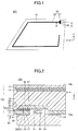
- Fig. 1 is a plan view of a resin plate body for window with a power feeding structure 100 of the embodiment.
- the "resin plate body for window including the power feeding structure” is referred to as a "plate body with a power feeding structure”.
- the plate body with the power feeding structure 100 is an example of a plate body with a power feeding structure for a side window attached at a side surface of an automobile.
- the plate body with the power feeding structure of the embodiment is not limited to outlines illustrated in the drawings, and may be one that is used for a window for a vehicle attached to the vehicle such as an automobile or the like, may be one that is used for a rear window attached to a rear portion of the vehicle, and one that is used for a roof window (sunroof) attached to a ceiling portion of the vehicle, for example.
- the plate body with the power feeding structure 100 is a resin plate body for window 10 including an electrical conductor pattern 20.
- the resin plate body for window 10 is a transparent or semitransparent plate member that is attached to a window frame of a vehicle, and is a member including a resin layer.
- the resin plate body for window 10 is a resin plate body for window in which a resin panel and a resin film at which the electrical conductor pattern 20 is provided are stacked such that the electrical conductor pattern 20 is interposed therebetween.
- the electrical conductor pattern 20 is a planar electrical conductor that is provided at the resin plate body for window 10.
- the electrical conductor pattern 20 includes a linear electrical conductor 22 and a power feeding portion 21.
- the linear electrical conductor 22 is an electrical conductor that is formed at the resin plate body for window 10
- the power feeding portion 21 is an electrical conductor for feeding power to the linear electrical conductor 22.
- the power feeding portion 21 is electrically connected to the linear electrical conductor 22 and is formed wider than the linear electrical conductor 22.
- the shape of the electrical conductor pattern 20 is not limited to that illustrated in the drawings and the electrical conductor pattern 20 may be arbitrarily formed in other shapes.
- the linear electrical conductor 22 and the power feeding portion 21 are formed such that they are provided inside the resin plate body for window 10, the linear electrical conductor 22 may be formed at a surface of the resin plate body for window 10.
- the linear electrical conductor 22 may be electrically connected to the power feeding portion 21 that is provided inside the resin plate body for window 10 by capacitive coupling, for example.
- the linear electrical conductor 22 corresponds to an antenna element or a feeder to an antenna element. Further, when the electrical conductor pattern 20 is a defogger that prevents fog of the resin plate body for window 10, for example, the linear electrical conductor 22 corresponds to a heater line.
- the electrical conductor pattern 20 may be used for other purposes.
- the power feeding portion 21 is not limited to a portion for feeding power to a linear element such as the linear electrical conductor 22, and may be a portion for feeding power to an arbitrary electrical conductor such as an electrical conductive film or the like formed at the resin plate body for window 10.
- feeding power may mean to feed power to an electrical conductor such as the linear electrical conductor 22 or the like, or may mean receiving power from an electrical conductor such as the linear electrical conductor 22 or the like.
- a power feeding component 30 is electrically connected to the power feeding portion 21.
- the power feeding component 30 is a terminal component used for feeding power to the electrical conductor pattern 20, and feeds power to the electrical conductor such as the linear electrical conductor 22 or the like via the power feeding portion 21.
- an electrical wire not illustrated in the drawings, such as a wire harness or the like of a vehicle is connected.
- the electrical conductor pattern 20 is an antenna electrical conductor
- the power feeding component 30 is connected to a receiver mounted on the vehicle via the electrical wire
- the electrical conductor pattern 20 is a defogger, for example, the power feeding component 30 is connected to a power source or ground mounted on the vehicle via the electrical wire.
- the power feeding component 30 may be a component including a signal processing circuit such as an amplifier or the like. Further, the power feeding component 30 may be just an electrical conductive metal terminal for electrically connecting the electrical wire and the power feeding portion 21.
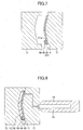
- Fig. 2 is a cross-sectional view of the plate body with the power feeding structure 100 taken along A-A of Fig. 1 .
- a lower side is inside of a vehicle, and a upper side an outside of the vehicle.
- the plate body with the power feeding structure 100 is the resin plate body for window 10 including a power feeding structure 80.
- the power feeding structure 80 includes an electrical conductive portion 40 that contacts a surface of the power feeding portion 21 of the electrical conductor pattern 20 provided inside the resin plate body for window 10, and is configured to feed power to the power feeding portion 21 of the electrical conductor pattern 20 via the electrical conductive portion 40.
- the surface of the power feeding portion 21 which the electrical conductive portion 40 contacts is an inside surface of the resin plate body for window 10 of two surfaces of the power feeding portion 21 in a thickness direction Z of the resin plate body for window 10.
- the thickness direction Z is a direction to view the resin plate body for window in a plan view and is a direction parallel to a Z axis, for the illustrated case.
- the electrical conductor pattern 20 is an example of an object to have power fed to which power is fed by the power feeding structure 80 via the electrical conductive portion 40.
- the power feeding structure 80 feeds power to the power feeding portion 21, to which the linear electrical conductor 22 is electrically connected, via the electrical conductive portion 40 and feeds power to the linear electrical conductor 22 via the power feeding portion 21.
- the electrical conductive portion 40 is provided at a resin sheet 50 and is an example of an electrical conductive portion that contacts the object to have power fed provided inside the resin plate body for window 10.
- the electrical conductive portion 40 is an electrical conductive layer that overlaps and contacts a surface of the power feeding portion 21 of the electrical conductor pattern 20 in the thickness direction Z, and is an electrical conductor provided inside the resin plate body for window 10.
- the power feeding structure 80 includes the resin sheet 50 provided inside the resin plate body for window 10 such that the electrical conductive portion 40 is interposed between the power feeding portion 21 of the electrical conductor pattern 20 and the resin sheet 50.
- the resin sheet 50 is an example of a resin sheet provided inside the resin plate body for window 10 such that the electrical conductive portion that contacts the object to have power fed provided inside the resin plate body for window 10 is interposed between the object to have power fed and the resin sheet.
- the resin sheet 50 is a resin sheet provided with a surface 51 that contacts a surface of the electrical conductive portion 40 opposite from the power feeding portion 21.
- the surface 51 is a surface that faces the power feeding portion 21 among the surfaces of the resin sheet 50 in the thickness direction Z.
- the resin sheet 50 may be a transparent polycarbonate sheet, for example, or may be a multiple layered sheet combined with another material.
- the resin sheet 50 is a resin material provided to be encapsulated in the resin panel 12. By forming the resin sheet 50 with a resin component similar to that of the resin panel 12, a stable bonding can be obtained as the resin sheet 50 and the resin panel 12 are strongly resin welded.
- the resin panel 12 is a resin panel placed inside the resin plate body for window 10, and is an injection molded resin material.
- the resin panel 12 is a transparent polycarbonate plate, for example.
- the electrical conductive portion 40 is interposed between the power feeding portion 21 of the electrical conductor pattern 20 and the resin sheet 50 provided inside the resin panel 12, a stable bonding of the electrical conductive portion 40 is ensured.
- the electrical conductive portion 40 does not include a portion that is bonded to the resin panel 12 in the thickness direction Z, and includes only a portion that is contacted to the resin panel 12 in a direction parallel to the XY plane that is perpendicular to the thickness direction Z.
- the electrical conductive portion 40 can be stably held by the resin panel 12.
- a difference between the coefficients of expansion of the resin sheet 50 and the resin panel 12 is smaller than a difference between the coefficients of expansion of the electrical conductive portion 40 and the resin panel 12.
- the electrical conductive portion 40 and the resin sheet 50 of the power feeding structure 80 are provided inside the resin plate body for window 10. Thus, even in a relative large shaking environment such as a vehicle or the like, durability of the plate body with the power feeding structure 100 can be ensured.
- a resin component 26 contained in the power feeding portion 21 of the electrical conductor pattern 20 and a resin component 46 contained in the electrical conductive portion 40 are resin welded (stuck) in the power feeding structure 80.
- the resin components of the resin component 26 and the resin component 46 are resin welded (stuck)
- a stable bonding of the electrical conductive portion 40 can be ensured.
- bonding strength between the power feeding portion 21 and the electrical conductive portion 40 can be increased.
- the resin plate body for window 10 is configured as a resin layer in which the resin film 11 and the resin panel 12 are stacked.
- the electrical conductor pattern 20, the electrical conductive portion 40 and the resin sheet 50 are provided between the resin film 11 and the resin panel 12.
- the resin panel 12 is bonded to a part of an inside surface 11b of the resin film 11.
- the resin film 11 is a resin film provided with an outside surface 11a that is exposed inside of the vehicle and an inside surface 11b that is opposite from the outside surface 11a.
- the outside surface 11a is also a surface 10a of the resin plate body for window 10 at inside of the vehicle.
- a hard coat process may be performed on the outside surface 11a.
- the electrical conductor pattern 20 is planarly formed on the inside surface 11b.
- the resin film 11 may be a transparent polycarbonate film, for example, or may be a multiple layered film combined with another material.
- the power feeding portion 21 and the linear electrical conductor 22 of the electrical conductor pattern 20 are printed electrical conductors planarly formed by screen printing of electrical conductive ink on the inside surface 11b of the resin film 11, for example.
- the electrical conductive ink is configured to include silver, which is an electrical conductive material (copper, gold, nickel, carbon, aluminum or the like is also usable).
- the resin film 11 has a thickness greater than or equal to 120 ⁇ m and less than or equal to 250 ⁇ m. By setting the thickness greater than or equal to 120 ⁇ m, wrinkles are hardly generated when performing injection molding.
- the electrical conductor pattern 20 is thinner than the resin film 11 and has a thickness greater than or equal to 7 ⁇ m and less than or equal to 45 ⁇ m. Although the thickness depends on a required resistance value, by setting within this range, the electrical conductor pattern 20 can be stably formed by screen printing.
- the electrical conductive portion 40 may be planarly formed on the surface 51 of the resin sheet 50, for example, and may be a printed electrical conductor that is planarly formed on the surface 51 of the resin sheet 50 by screen printing electrical conductive ink.
- the electrical conductive ink is configured to include silver, which is an electrical conductive material (copper, gold, nickel, carbon, aluminum or the like is also usable).
- the resin sheet 50 has a thickness greater than or equal to 120 ⁇ m and less than or equal to 250 ⁇ m, the electrical conductor pattern 20 is thinner than the resin sheet 50 and has a thickness greater than or equal to 7 ⁇ m and less than or equal to 45 ⁇ m.
- the power feeding structure 80 is provided with a power feeding hole 60 as a hole for feeding power from the surface 10a of the resin plate body for window 10 to reach the electrical conductive portion 40, for example.
- the surface 10a is a surface at the power feeding portion 21 of the electrical conductor pattern 20 side with respect to the electrical conductive portion 40, among the surfaces 10a and 10b of the resin plate body for window 10 in the thickness direction Z.
- the power feeding hole 60 is formed from the outside surface 11a to penetrate the resin film 11 to reach the surface 42 of the electrical conductive portion 40 that faces the power feeding portion 21.
- the number of the power feeding holes 60 is not limited to one and a plurality of holes may be formed. Further, the shape of the power feeding hole 60 may be a circle, a polygon or other arbitrarily selected shapes.
- the power feeding structure 80 includes the power feeding component 30 electrically connected to the power feeding portion 21 of the electrical conductor pattern 20 via the power feeding hole 60 and the electrical conductive portion 40.
- the power feeding hole 60 is provided, even when the power feeding portion 21 of the electrical conductor pattern 20 is provided inside the resin plate body for window 10, it is easy to feed power to the power feeding portion 21 via the power feeding hole 60 and the electrical conductive portion 40 by electrically connecting the power feeding component 30 to the power feeding portion 21.
- the power feeding component 30 it is easy for the power feeding component 30 to electrically conductively contact the surface 42 of the electrical conductive portion 40 at the power feeding portion 21 side via the power feeding hole 60.
- the power feeding component 30 is provided at the outside surface 11a of the resin film 11 via an adhesive material 41.
- the outside surface 11a is the surface 10a of the resin plate body for window 10 at which the power feeding hole 60 is provided.
- the adhesive material 41 is provided between the resin film 11 and the power feeding component 30 and is an adhesive layer for adhering the resin film 11 and the power feeding component 30.
- an adhesive agent, an adhesive tape or the like may be used.
- the power feeding component 30 can be easily attached and fixed to the outside surface 11a of the resin film 11 by the adhesive material 41. Further, as the power feeding component 30 can be attached to the resin plate body for window 10 without using a tapping screw by using the adhesive material 41, durability of the power feeding structure 80 and the resin plate body for window 10 can be improved.
- the power feeding component 30 conductively contacts the surface 42 of the electrical conductive portion 40 via a contacting portion 31 provided in the power feeding hole 60 formed at the resin plate body for window 10, for example. It is possible to further easily conductively connect the power feeding component 30 and the electrical conductive portion 40 by the contacting portion 31.
- the contacting portion 31 is a portion (component) at the power feeding component 30 side, and is provided to protrude from a surface of the power feeding component 30 at the power feeding portion 21 side.
- the contacting portion 31 may not be a portion at the power feeding component 30 and may be a portion (component) at the electrical conductive portion 40 side, and may be provided to protrude from the surface 42 toward the power feeding portion 21 side.
- the contacting portion 31 may be a single component or a portion (component) configured with a plurality of members including members not illustrated in the drawings.
- the contacting portion 31 is an electrical conductive elastic body because durability in assembling the power feeding component 30 and the resin plate body for window 10 is improved while a sufficient electrical conductivity between the power feeding component 30 and the electrical conductive portion 40 is ensured.
- the power feeding component 30 may be fixed to the outside surface 11a by the adhesive material 41 under a state that the contacting portion 31 is elastically deformed while being in contact with the surface 42 of the electrical conductive portion 40. With this configuration, even when the resin plate body for window 10 is oscillated due to a shaking of a vehicle or the like, sufficient electrical conductivity between the power feeding component 30 and the electrical conductive portion 40 and durability can be ensured by absorbing oscillation by deformation of the contacting portion 31.
- a leaf spring, a spring coil, a rubber or the like may be used.
- the power feeding component 30 may conductively contact the electrical conductive portion 40 via an electrical conductive adhesive agent.
- the contacting portion 31 can be adhered to the electrical conductive portion 40 and/or the power feeding component 30 by an electrical conductive adhesive agent such as an electrical conductive adhesive agent, solder or the like, or the contacting portion 31 may be substituted for by an electrical conductive adhesive agent such as an electrical conductive adhesive agent, solder or the like.
- the resin plate body for window 10 may include a concealing layer 14 that conceals a part of the electrical conductor pattern 20 and the electrical conductive portion 40 in a plan view in the thickness direction Z from outside toward inside of the vehicle at an opposite side of the power feeding portion 21 with respect to the electrical conductive portion 40 (this means at the resin sheet 50 with respect to the electrical conductive portion 40).
- the part of the electrical conductor pattern 20 concealed by the concealing layer 14 is a part or the entirety of the power feeding portion 21, for example.
- the concealing layer 14 is formed at the film with a concealing layer 13 that is provided opposite side of the power feeding portion 21 with respect to the electrical conductive portion 40.
- the film with the concealing layer 13 is bonded to the resin panel 12 and the concealing layer 14 is interposed between the resin panel 12 and the film with the concealing layer 13.
- the film with the concealing layer 13 is a transparent polycarbonate film, for example.
- the concealing layer 14 may be black paint, for example.
- Fig. 3 is a flowchart illustrating an example of a method of manufacturing the plate body with the power feeding structure 100.
- a preparing step of step S1 of Fig. 3 is a step of preparing the resin film 11 provided with the electrical conductor pattern 20, and the resin sheet 50 provided with the electrical conductive portion 40.
- the preparing step of step S1 is a step of forming the electrical conductor pattern 20 by printing electrical conductive ink on the resin film 11, for example.
- the step is a step of forming the electrical conductive portion 40 by printing electrical conductive ink on the resin sheet 50.
- the step may include a step of baking the electrical conductive ink or a step of drying and evaporating solvent.
- a stacking step of step S2 of Fig. 3 is a step of stacking the resin film 11 and the resin sheet 50 such that the electrical conductive portion 40 is interposed between the surface 21a of the power feeding portion 21 of the electrical conductor pattern 20 and the resin sheet 50.
- the surface 21a is a surface at the outside of the vehicle that is opposite from the resin film 11.
- the stacking step of step S2 is a step of stacking the resin sheet 50 at which the electrical conductive portion 40 is formed on the inside surface 11b of the resin film 11 such that the electrical conductive portion 40 and the power feeding portion 21 make contact, for example.
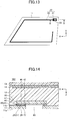
- Fig. 6 is a cross-sectional view at a YZ plane seen from an X axis direction of Fig. 5 .
- the resin sheet 50 is temporarily adhered at the inside surface 11b of the resin film 11 by an adhering portion 90 (the adhering portion 90 is not illustrated in Fig. 5 for explanation purposes).
- the adhering portion 90 By the adhering portion 90, the resin sheet 50 is prevented from being separated from the resin film 11 in a setting step of step S3, which will be explained later.
- a double sided tape or an adhesive material may be used.
- the adhering portion 90 may be a portion at which the resin sheet 50 and the resin film 11 are resin welded by heat. For example, when overlapping the resin sheet 50 and the resin film 11, by heating the resin sheet 50 and the resin film 11 in the thickness direction Z, the resin sheet 50 and the resin film 11 can be thermally resin welded (stuck) by the adhering portion 90.
- the stacking step of step S2 may include a step of providing a tape for peeling 91 between the electrical conductive portion 40 and the resin film 11.
- the tape for peeling 91 is a welding suppressing member that suppresses resin welding of the resin component 46 contained in the electrical conductive portion 40 and the resin component 16 contained in the resin film 11 by the heat and the pressure in an injection molding step S4, which will be explained later.
- the welding suppressing member such as the tape for peeling 91 or the like has a melting point higher than that of the temperature (heat) at the injection molding in order not to be melted by the heat at the injection molding. It is preferable that the tape for peeling 91 is a tape made of fluroresin or polyimide.
- the setting step of step S3 of Fig. 3 is a step of setting the resin film 11 in which the resin sheet 50 with the electrical conductive portion 40 is stacked and adhered to the surface 21a of the power feeding portion 21 of the electrical conductor pattern 20, in an injection die for manufacturing the plate body with a power feeding structure.
- the injection die is a die including a first die 71 and a second die 72, for example.
- the resin film 11 is set in a die (cavity) of the first die 71 and the second die 72 while being aligned at the first die 71.
- electrostatic, a magnet, a pin or the like may be used, for example.
- the injection molding step of step S4 of Fig. 3 is a step of molding by injecting a molten resin 74 (molten polycarbonate, for example) in the die (in the cavity) of the first die 71 and the second die 72.
- a molten resin 74 molten polycarbonate, for example
- the molten resin 74 reserved in a heating cylinder 73 is injected and filled in the cavity.
- the resin component 26 contained in the power feeding portion 21 of the electrical conductor pattern 20 and the resin component 46 contained in the electrical conductive portion 40 are resin welded (stuck) by the heat at the injection molding, bonding strength between the power feeding portion 21 and the electrical conductive portion 40 can be increased.
- a removing step of opening the first die 71 and the second die 72 is performed and an injection molded part is obtained. With this configuration, the resin panel 12 is formed when the molten resin 74 is solidified (see Fig. 9 ).
- both of the resin sheet 50 and the resin panel 12 contain resin components, respectively, compatibility between the resin components contained in the resin sheet 50 and the resin panel 12, respectively, is high. Thus, even when the resin sheet 50 is injection molded such that to be encapsulated in the resin panel 12, a sufficient bonding between the resin sheet 50 and the resin panel 12 can be ensured.
- Each of the resin component 26 contained in the electrical conductor pattern 20 and the resin component 46 contained in the electrical conductive portion 40 has a melting point lower than that of a resin material (the resin panel 12, the resin sheet 50, the resin film 11 or the like, for example) that contacts the electrical conductor pattern 20 or the electrical conductive portion 40. It is for preventing the resin material that contacts the conductor pattern 20 or the electrical conductive portion 40 from being melted by the heat at the injection molding before the resin components 26 and 46 are melted.
- each of the resin components 26 and 46 has a melting point higher than the temperature at which the power feeding component 30 or the contacting portion 31 is attached to the resin plate body for window 10 in a providing step of step S6, which will be explained later.
- each of the resin components 26 and 46 has a melting point higher than 150 °C to 200 °C. This is to prevent the resin components 26 and 46 from being melted by the attaching temperature of the power feeding component 30 or the like.
- each of the resin components 26 and 46 has a thermoplastic property.
- thermoplastic property it is easier for the electrical conductive portion 40 and the electrical conductor pattern 20 to deform in accordance with the deformation of the resin material that contacts the electrical conductor pattern 20 and the electrical conductive portion 40 due to heat expansion, respectively. With this, bonding stability between the electrical conductive portion 40 and the electrical conductor pattern 20 can be improved.
- thermoplastic resin component polyester, polyvinyl chloride, acrylate resin, polyolefin or the like may be used, for example.
- each of the electrical conductor pattern 20 and the electrical conductive portion 40 contains a metal component in addition to the resin component.
- the electrical conductor pattern 20 contains a metal component 27 and the electrical conductive portion 40 contains a metal component 47.
- the electrical conductive portion 40 contains the metal component 47 and the resin component 46 by the ratio of the Equation 1, the Equation 2 or the Equation 3.
- each of the electrical conductor pattern 20 and the electrical conductive portion 40 contains the metal component and the resin component by such a weight ratio, an effect to increase the bonding stability between the electrical conductor pattern 20 and the electrical conductive portion 40 becomes large.
- the metal components 27 and 47 in an order having a higher effect of increasing stability, gold, silver, copper or the like may be used.
- a step of forming a hole of step S5 of Fig. 3 is a step of forming the power feeding hole 60 by linearly penetrating the resin film 11 from the outside surface 11a to reach the electrical conductive portion 40. With this, a plate body with power feeding structure 101 is obtained.
- the step of forming hole of step S5 is performed after the injection molding step of step S4. If the step of forming hole is performed before the injection molding step, a deformation amount of the electrical conductive portion 40 in a convex shape toward the power feeding hole 60 in the injection molding tends to become large, and the bonding stability between the electrical conductive portion 40 and the electrical conductor pattern 20 tends to be lowered. On the other hand, if the step of forming hole is performed after the injection molding step, the deformation amount of the electrical conductive portion 40 in the injection molding can be suppressed, and it is possible to suppress lowering of the bonding stability between the electrical conductive portion 40 and the electrical conductor pattern 20.
- a tape for peeling 91 (see Fig. 9 ) is interposed between the electrical conductive portion 40 and the resin film 11. Due to the tape for peeling 91, the resin component 46 contained in the electrical conductive portion 40 and the resin component 16 contained in the resin film 11 are suppressed to be welded by the heat and the pressure at the injection molding. Thus, the resin film 11 can be easily removed by peeling. By removing the resin film 11 by peeling, the power feeding hole 60 of Fig. 10 can be easily formed.
- a cut portion 61 such as perforation or the like (see Fig. 4 , Fig. 9 ) is formed in the resin film 11 in the preparing step of step S1.
- the resin film 11 can be easily removed by peeling along the cut portion 61 at a state of Fig. 9 .
- the power feeding hole 60 of Fig. 10 can be easily formed.
- the cut portion 61 has an outline width L1 that is narrower than an outline width L2 of a portion of the electrical conductive portion 40 that is not bonded to the power feeding portion 21.
- Fig. 6 illustrates outline widths in a direction that is in parallel to a Y axis
- the cut portion 61 has an outline width narrower than an outline width of the electrical conductive portion 40 that is not bonded to the power feeding portion 21 in each of the directions in an XY plane.
- the film with the concealing layer 13 at which the concealing layer 14 that conceals the power feeding portion 21 and the electrical conductive portion 40 in a plan view is planarly formed may be set at the second die 72 such that to be positioned opposite from the power feeding portion 21 with respect to the electrical conductive portion 40.
- the film with the concealing layer 13 is integrally formed with the resin panel 12 and a plate body with power feeding structure 102 in which the concealing layer 14 is formed is obtained.
- a providing step of the power feeding component of step S6 of Fig. 3 is a step of providing the power feeding component 30 at the outside surface 11a of the resin film 11 so as to be electrically connected to the power feeding portion 21 via the power feeding hole 60 and the electrical conductive portion 40.
- the power feeding component 30 is provided at the outside surface 11a of the resin film 11 to conductively contact the electrical conductive portion 40 via the power feeding hole 60.
- the power feeding component 30 is fixed to the resin plate body for window 10 by being adhered at the outside surface 11a by the adhesive material 41.
- a plate body with a power feeding structure 200 including a power feeding structure different from that of the plate body with the power feeding structure 100 is described.
- components same as those of the plate body with the power feeding structure 100 are given the same reference numerals, and explanations are not repeated.
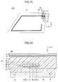
- Fig. 15 is a plan view of a plate body with a power feeding structure 200 of an embodiment.
- the plate body with the power feeding structure 200 is different from the plate body with the power feeding structure 100 of Fig. 1 in an embodiment of providing the resin plate body for window 10 and the power feeding component 30.
- a notch or a hole is provided at a part of the resin film 11 at a periphery of the power feeding portion 21.
- Fig. 16 is a cross-sectional view illustrating the plate body with the power feeding structure 200, and is a C-C cross-section of Fig. 15 .
- a bracket 15 is integrally formed with the resin panel 12 of the resin plate body for window 10.
- the bracket 15 provided at the resin plate body for window 10 is an attaching leg for fixing the power feeding component 30 to the outside surface 11a of the resin film 11, and includes a hooking portion for hooking and fixing the power feeding component 30, for example.
- the power feeding component 30 is provided at the outside surface 11a of the resin film 11 via the bracket 15.
- the bracket 15 is integrally injection molded with the resin panel 12 of the resin plate body for window 10 with the resin panel 12 in the injection molding step of step S4 of Fig. 3 .
Landscapes
- Engineering & Computer Science (AREA)
- Mechanical Engineering (AREA)
- Power Engineering (AREA)
- Transportation (AREA)
- Manufacturing & Machinery (AREA)
- Injection Moulding Of Plastics Or The Like (AREA)
- Details Of Aerials (AREA)
Claims (11)
- Structure d'alimentation électrique (80) comprenant :un corps de plaque en résine pour une fenêtre (10) comprenant un panneau en résine empilé (12) et un film de résine (11) et un objet devant être alimenté en puissance, dans laquelle l'objet devant être alimenté en puissance est interposé entre le panneau en résine (12) et le film de résine (11), etune portion conductrice électrique (40) qui est configurée pour venir en contact avec l'objet devant être alimenté en puissance et qui est prévue à l'intérieur du corps de plaque en résine pour une fenêtre (10),la structure d'alimentation électrique (80) est configurée pour alimenter de la puissance à l'objet devant être alimenté en puissance par le biais de la portion conductrice électrique (40),la structure d'alimentation électrique comprenant en outre une feuille de résine (50), dans laquelle la portion conductrice électrique (40) est prévue sur la feuille de résine (50),la feuille de résine (50) est prévue à l'intérieur du corps de plaque de sorte que la portion conductrice électrique (40) est interposée entre la feuille de résine (50) et l'objet devant être alimenté en puissance,le panneau en résine (12) et la feuille de résine (50) étant soudés par résine, etla structure d'alimentation électrique comprenant en outre des composants de résine (26, 46) contenus dans l'objet devant être alimenté en puissance et la portion conductrice électrique (40), respectivement, qui sont soudés par résine les uns aux autres, etdans laquelle la structure d'alimentation électrique (80) est pourvu d'un orifice d'alimentation électrique (60) formé depuis une surface du corps de plaque de manière à atteindre la portion conductrice électrique (40), et la structure d'alimentation électrique (80) comprenant en outre un composant d'alimentation électrique connecté électriquement à l'objet devant être alimenté en puissance par le biais de l'orifice d'alimentation électrique (60) et la portion conductrice électrique (40).
- Structure d'alimentation électrique (80) selon la revendication 1,
dans laquelle la portion conductrice électrique (40) est un conducteur électrique imprimé formé au niveau d'une surface de la feuille de résine (50). - Structure d'alimentation électrique (80) selon la revendication 1 ou 2,
dans laquelle chacun des composants de résine (26, 46) a une propriété thermoplastique. - Structure d'alimentation électrique (80) selon une des revendications 1 à 3,
dans laquelle chacun des composants de résine (26, 46) a un point de fusion inférieur à celui d'un matériau de résine qui est configuré pour venir en contact avec l'objet devant être alimenté en puissance ou la portion conductrice électrique (40). - Structure d'alimentation électrique (80) selon une des revendications 1 à 4,
dans laquelle chacun de l'objet devant être alimenté en puissance et de la portion conductrice électrique (40) contient un composant métallique (27, 47) outre le composant de résine respectif (26, 46), et contient le composant métallique (27, 47) et le composant de résine (26, 46) par un rapport pondéral de
α/β qui est supérieur ou égal à 7/3 et inférieur ou égal à 19/1, où un poids du composant métallique est « α » et un poids du composant de résine est « β ». - Structure d'alimentation électrique (80) selon la revendication 1,
dans laquelle le composant d'alimentation électrique est prévu au niveau d'une surface du corps de plaque au niveau de laquelle l'orifice d'alimentation électrique (60) est formé par le biais d'un support (15) prévu au niveau du corps de plaque. - Corps de plaque en résine pour une fenêtre (10) comprenant la structure d'alimentation électrique (80) selon une des revendications 1 à 6.
- Procédé de fabrication d'un corps de plaque en résine pour une fenêtre (10) incluant une structure d'alimentation électrique (80), comprenant :une étape de préparation consistant à préparer un film de résine (11) au niveau duquel un objet devant être alimenté en puissance est prévu et une feuille de résine (50) au niveau de laquelle une portion conductrice électrique (40) est prévue ;une étape d'empilement consistant à empiler le film de résine (11) et la feuille de résine (50) de sorte que la portion conductrice électrique (40) est interposée entre l'objet devant être alimenté en puissance et la feuille de résine (50) ;une étape de durcissement consistant à faire durcir le film de résine (11) sur lequel la feuille de résine (50) est empilée au niveau d'un moule à injection ;une étape de moulage par injection consistant à injecter de la résine fondue dans le moule à injection ;une étape de formation d'un orifice, après l'étape de moulage par injection, consistant à former un orifice d'alimentation électrique (60) depuis une surface du film de résine (11) de manière à atteindre la portion conductrice électrique (40) ; etune étape de fourniture consistant à fournir un composant d'alimentation électrique (30) de manière à être connecté électriquement à l'objet devant être alimenté en puissance par le biais de l'orifice d'alimentation électrique (60) et la portion conductrice électrique (40) après l'étape de moulage par injection,dans lequel une portion découpée pour former l'orifice dans l'étape de formation d'un orifice est formée au niveau du film de résine (11) dans l'étape de préparation.
- Procédé de fabrication du corps de plaque en résine pour une fenêtre (10) incluant la structure d'alimentation électrique (80) selon la revendication 8,
dans lequel la portion découpée a une largeur de contour plus étroite que celle de la portion conductrice électrique (40). - Procédé de fabrication du corps de plaque en résine pour une fenêtre (10) incluant la structure d'alimentation électrique (80) selon la revendication 8 ou 9,
dans lequel un élément de suppression de soudure qui supprime une soudure par résine de composants de résine (16, 46) contenus dans la portion conductrice électrique (40) et le film de résine (11), respectivement, dans l'étape de moulage par injection est prévu entre la portion conductrice électrique (40) et le film de résine (11) dans l'étape d'empilement. - Procédé de fabrication du corps de plaque en résine pour une fenêtre (10) incluant la structure d'alimentation électrique (80) selon une des revendications 8 à 10,
dans lequel un support (15) est intégralement formé avec le corps de plaque en résine pour une fenêtre (10) qui fixe un composant d'alimentation électrique (30) dans l'étape de moulage par injection.
Applications Claiming Priority (2)
| Application Number | Priority Date | Filing Date | Title |
|---|---|---|---|
| JP2013215855 | 2013-10-16 | ||
| PCT/JP2014/076537 WO2015056582A1 (fr) | 2013-10-16 | 2014-10-03 | Structure d'alimentation en électricité, plaque en résine pour fenêtre dotée de ladite structure et procédé de production de plaque en résine pour fenêtre dotée de structure d'alimentation en électricité |
Publications (3)
| Publication Number | Publication Date |
|---|---|
| EP3059801A1 EP3059801A1 (fr) | 2016-08-24 |
| EP3059801A4 EP3059801A4 (fr) | 2017-06-07 |
| EP3059801B1 true EP3059801B1 (fr) | 2019-04-24 |
Family
ID=52828030
Family Applications (1)
| Application Number | Title | Priority Date | Filing Date |
|---|---|---|---|
| EP14853433.2A Active EP3059801B1 (fr) | 2013-10-16 | 2014-10-03 | Structure d'alimentation en électricité, plaque en résine pour fenêtre dotée de ladite structure et procédé de production de plaque en résine pour fenêtre dotée de structure d'alimentation en électricité |
Country Status (5)
| Country | Link |
|---|---|
| US (1) | US9873330B2 (fr) |
| EP (1) | EP3059801B1 (fr) |
| JP (1) | JP6350533B2 (fr) |
| CN (1) | CN105637705B (fr) |
| WO (1) | WO2015056582A1 (fr) |
Families Citing this family (9)
| Publication number | Priority date | Publication date | Assignee | Title |
|---|---|---|---|---|
| CN105637705B (zh) * | 2013-10-16 | 2019-04-19 | Agc株式会社 | 供电结构、窗用树脂制板状体及其制造方法 |
| JP6753414B2 (ja) * | 2015-11-05 | 2020-09-09 | Agc株式会社 | 電気接続構造、端子付きガラス板、及び端子付きガラス板の製造方法 |
| JP2017149380A (ja) * | 2016-02-26 | 2017-08-31 | イビデン株式会社 | 樹脂製リアウインドウ及び樹脂製ウインドウ |
| JP6832658B2 (ja) * | 2016-09-23 | 2021-02-24 | スタンレー電気株式会社 | 光透過基板、表示装置、信号装置、および、照明装置 |
| DE102018123268A1 (de) * | 2018-09-21 | 2020-03-26 | Webasto SE | Deckel für ein Fahrzeugdach eines Kraftfahrzeugs, Dachanordnung für ein Kraftfahrzeug sowie Verfahren zum Herstellen eines Deckels |
| DE102020004282A1 (de) * | 2019-07-24 | 2021-01-28 | AGC lnc. | Elektrische verbindungsstruktur |
| JP2022026581A (ja) * | 2020-07-31 | 2022-02-10 | 株式会社日本製鋼所 | 成形方法および成形システム |
| WO2023090245A1 (fr) * | 2021-11-19 | 2023-05-25 | Agc株式会社 | Structure d'alimentation électrique, corps en forme de plaque et verre de fenêtre |
| WO2023176727A1 (fr) * | 2022-03-17 | 2023-09-21 | Agc株式会社 | Dispositif d'antenne de véhicule |
Family Cites Families (26)
| Publication number | Priority date | Publication date | Assignee | Title |
|---|---|---|---|---|
| DE8815848U1 (fr) * | 1988-12-21 | 1989-02-09 | Flachglas Ag, 8510 Fuerth, De | |
| US6043782A (en) * | 1995-12-18 | 2000-03-28 | Ppg Industries Ohio, Inc. | Antenna connector arrangement |
| JP2000006654A (ja) | 1998-06-19 | 2000-01-11 | Toyota Autom Loom Works Ltd | 導線入り樹脂ウインド及びその製造法 |
| JP4207321B2 (ja) * | 1999-07-29 | 2009-01-14 | 株式会社豊田自動織機 | 印刷入り樹脂パネル及びインサート用フィルム又はシート |
| ES2261981T3 (es) * | 2002-09-10 | 2006-11-16 | Saint-Gobain Glass France | Dispositivo de conexion para un elemento plano en varias capas equipado de elementos funcionales electricos y elemento plano. |
| US8653419B2 (en) * | 2004-05-17 | 2014-02-18 | Exatec Llc | Window defroster assembly having transparent conductive layer |
| US7223939B2 (en) * | 2004-11-12 | 2007-05-29 | Agc Automotive Americas, R & D, Inc. | Electrical connector for a window pane of a vehicle |
| EP1770676B1 (fr) * | 2005-09-30 | 2017-05-03 | Semiconductor Energy Laboratory Co., Ltd. | Dispositif d'affichage et dispositif électronique |
| JP4696827B2 (ja) * | 2005-10-11 | 2011-06-08 | 旭硝子株式会社 | 車両窓用樹脂製板状体およびその製造方法 |
| US7612727B2 (en) | 2005-12-29 | 2009-11-03 | Exatec, Llc | Antenna for plastic window panel |
| EP1895545B1 (fr) * | 2006-08-31 | 2014-04-23 | Semiconductor Energy Laboratory Co., Ltd. | Dispositif d'affichage aux cristaux liquides |
| JP2008072471A (ja) * | 2006-09-14 | 2008-03-27 | Nippon Sheet Glass Co Ltd | 車両用フィルムアンテナ装置 |
| TWI442368B (zh) * | 2006-10-26 | 2014-06-21 | Semiconductor Energy Lab | 電子裝置,顯示裝置,和半導體裝置,以及其驅動方法 |
| JP5216204B2 (ja) * | 2006-10-31 | 2013-06-19 | 株式会社半導体エネルギー研究所 | 液晶表示装置及びその作製方法 |
| FR2921520B1 (fr) * | 2007-09-20 | 2014-03-14 | Saint Gobain | Element de connexion electrique et vitrage pourvu d'un tel element |
| JP2009180769A (ja) * | 2008-01-29 | 2009-08-13 | Seiko Epson Corp | カラーフィルター用インクセット、カラーフィルターの製造方法、カラーフィルター、画像表示装置、および、電子機器 |
| CN103237657A (zh) * | 2010-12-06 | 2013-08-07 | 柯尼卡美能达株式会社 | 气体阻隔性膜、气体阻隔性膜的制造方法及电子器件 |
| EA026715B1 (ru) | 2011-04-06 | 2017-05-31 | Сэн-Гобэн Гласс Франс | Ленточный соединительный элемент для антенной конструкции |
| PT2794366T (pt) * | 2011-12-20 | 2017-03-29 | Saint Gobain | Placa de vidro polímera com estrutura condutora de eletricidade |
| WO2014021970A2 (fr) * | 2012-05-08 | 2014-02-06 | Battelle Memorial Institute | Cellule multifonction pour applications structurales |
| WO2013172359A1 (fr) * | 2012-05-14 | 2013-11-21 | コニカミノルタ株式会社 | Film de barrière vis-à-vis des gaz, procédé de fabrication pour film de barrière vis-à-vis des gaz, et dispositif électronique |
| JP6171876B2 (ja) | 2012-11-14 | 2017-08-02 | 旭硝子株式会社 | 給電構造及びそれを備えた窓用樹脂製板状体、並びに給電構造を備えた窓用樹脂製板状体の製造方法 |
| CN105637705B (zh) * | 2013-10-16 | 2019-04-19 | Agc株式会社 | 供电结构、窗用树脂制板状体及其制造方法 |
| US20170131445A1 (en) * | 2014-07-30 | 2017-05-11 | Konica Minolta, Inc. | Optical film and method for manufacturing optical film |
| US10384649B2 (en) * | 2014-11-17 | 2019-08-20 | Dai Nippon Printing Co., Ltd. | Heating plate, conductive pattern sheet, vehicle, and method of manufacturing heating plate |
| JP2017005354A (ja) * | 2015-06-05 | 2017-01-05 | 旭硝子株式会社 | 車両用ガラスアンテナ及び車両用アンテナを備えた後部窓ガラス |
-
2014
- 2014-10-03 CN CN201480056548.6A patent/CN105637705B/zh active Active
- 2014-10-03 JP JP2015542572A patent/JP6350533B2/ja active Active
- 2014-10-03 WO PCT/JP2014/076537 patent/WO2015056582A1/fr active Application Filing
- 2014-10-03 EP EP14853433.2A patent/EP3059801B1/fr active Active
-
2016
- 2016-04-12 US US15/096,598 patent/US9873330B2/en active Active
Non-Patent Citations (1)
| Title |
|---|
| None * |
Also Published As
| Publication number | Publication date |
|---|---|
| US9873330B2 (en) | 2018-01-23 |
| JP6350533B2 (ja) | 2018-07-04 |
| WO2015056582A1 (fr) | 2015-04-23 |
| CN105637705A (zh) | 2016-06-01 |
| US20160221442A1 (en) | 2016-08-04 |
| EP3059801A1 (fr) | 2016-08-24 |
| EP3059801A4 (fr) | 2017-06-07 |
| JPWO2015056582A1 (ja) | 2017-03-09 |
| CN105637705B (zh) | 2019-04-19 |
Similar Documents
| Publication | Publication Date | Title |
|---|---|---|
| EP3059801B1 (fr) | Structure d'alimentation en électricité, plaque en résine pour fenêtre dotée de ladite structure et procédé de production de plaque en résine pour fenêtre dotée de structure d'alimentation en électricité | |
| EP2953210B1 (fr) | Module électronique monté sur véhicule | |
| JP5401462B2 (ja) | 電気接続エレメントおよびそのようなエレメントを備えるディスク | |
| US6103998A (en) | Resin windows having electrically conductive terminals | |
| JP6211823B2 (ja) | 自動車用ウインドウガラス及びその製造方法 | |
| EP2833489A2 (fr) | Module de dispositif électronique | |
| KR20060009848A (ko) | 안테나 장치 | |
| EP3734745A1 (fr) | Ensemble fpcb pour module de batterie, son procédé de fabrication, et module de batterie le comprenant | |
| US10601149B2 (en) | Window assembly with casing for solder joint | |
| EP1157892A1 (fr) | Joint de faisceau de câbles | |
| US9345134B2 (en) | Printed wiring board | |
| JP2008270021A (ja) | 導電体付き板状体及びその製造方法 | |
| EP4015186A1 (fr) | Procédé de fabrication d'une structure tridimensionnelle et structure tridimensionnelle | |
| US20120031662A1 (en) | Sensor module having an electromagnetically shielded electrical component | |
| JP2018094949A (ja) | 車両用窓ガラス及び車両用窓ガラスの製造方法 | |
| JP6171876B2 (ja) | 給電構造及びそれを備えた窓用樹脂製板状体、並びに給電構造を備えた窓用樹脂製板状体の製造方法 | |
| CN114556685B (zh) | 布线模块 | |
| US10111324B2 (en) | Electrical component | |
| JP6699584B2 (ja) | 導電性ペースト層と給電部を備えた樹脂部材の製造方法、および導電性ペースト層と給電部を備えた樹脂部材と外部給電部材の接続方法 | |
| CN113632446A (zh) | 电子设备、拍摄装置以及移动体 | |
| CN207800890U (zh) | 车载天线装置以及车载天线装置的供电端子部 | |
| JP3417123B2 (ja) | フラット・ハーネス | |
| JP2005167666A (ja) | アンテナ装置を備えた成形品及びその製造方法 | |
| JP2002160519A (ja) | 車両用樹脂製窓 | |
| JP2001052846A (ja) | 導線入り窓とその製造方法 |
Legal Events
| Date | Code | Title | Description |
|---|---|---|---|
| PUAI | Public reference made under article 153(3) epc to a published international application that has entered the european phase |
Free format text: ORIGINAL CODE: 0009012 |
|
| 17P | Request for examination filed |
Effective date: 20160414 |
|
| AK | Designated contracting states |
Kind code of ref document: A1 Designated state(s): AL AT BE BG CH CY CZ DE DK EE ES FI FR GB GR HR HU IE IS IT LI LT LU LV MC MK MT NL NO PL PT RO RS SE SI SK SM TR |
|
| AX | Request for extension of the european patent |
Extension state: BA ME |
|
| DAX | Request for extension of the european patent (deleted) | ||
| REG | Reference to a national code |
Ref country code: DE Ref legal event code: R079 Ref document number: 602014045506 Country of ref document: DE Free format text: PREVIOUS MAIN CLASS: H01Q0001320000 Ipc: H01Q0001120000 |
|
| A4 | Supplementary search report drawn up and despatched |
Effective date: 20170511 |
|
| RIC1 | Information provided on ipc code assigned before grant |
Ipc: H01Q 1/12 20060101AFI20170504BHEP |
|
| STAA | Information on the status of an ep patent application or granted ep patent |
Free format text: STATUS: EXAMINATION IS IN PROGRESS |
|
| 17Q | First examination report despatched |
Effective date: 20180321 |
|
| RAP1 | Party data changed (applicant data changed or rights of an application transferred) |
Owner name: AGC INC. |
|
| GRAP | Despatch of communication of intention to grant a patent |
Free format text: ORIGINAL CODE: EPIDOSNIGR1 |
|
| STAA | Information on the status of an ep patent application or granted ep patent |
Free format text: STATUS: GRANT OF PATENT IS INTENDED |
|
| INTG | Intention to grant announced |
Effective date: 20181212 |
|
| GRAS | Grant fee paid |
Free format text: ORIGINAL CODE: EPIDOSNIGR3 |
|
| GRAA | (expected) grant |
Free format text: ORIGINAL CODE: 0009210 |
|
| STAA | Information on the status of an ep patent application or granted ep patent |
Free format text: STATUS: THE PATENT HAS BEEN GRANTED |
|
| RIN1 | Information on inventor provided before grant (corrected) |
Inventor name: WATANABE, MITSUROU Inventor name: ATSUMI, TOSHIHIRO |
|
| AK | Designated contracting states |
Kind code of ref document: B1 Designated state(s): AL AT BE BG CH CY CZ DE DK EE ES FI FR GB GR HR HU IE IS IT LI LT LU LV MC MK MT NL NO PL PT RO RS SE SI SK SM TR |
|
| REG | Reference to a national code |
Ref country code: GB Ref legal event code: FG4D |
|
| REG | Reference to a national code |
Ref country code: CH Ref legal event code: EP |
|
| REG | Reference to a national code |
Ref country code: AT Ref legal event code: REF Ref document number: 1125235 Country of ref document: AT Kind code of ref document: T Effective date: 20190515 Ref country code: IE Ref legal event code: FG4D |
|
| REG | Reference to a national code |
Ref country code: DE Ref legal event code: R096 Ref document number: 602014045506 Country of ref document: DE |
|
| REG | Reference to a national code |
Ref country code: NL Ref legal event code: MP Effective date: 20190424 |
|
| REG | Reference to a national code |
Ref country code: LT Ref legal event code: MG4D |
|
| PG25 | Lapsed in a contracting state [announced via postgrant information from national office to epo] |
Ref country code: NL Free format text: LAPSE BECAUSE OF FAILURE TO SUBMIT A TRANSLATION OF THE DESCRIPTION OR TO PAY THE FEE WITHIN THE PRESCRIBED TIME-LIMIT Effective date: 20190424 |
|
| PG25 | Lapsed in a contracting state [announced via postgrant information from national office to epo] |
Ref country code: LT Free format text: LAPSE BECAUSE OF FAILURE TO SUBMIT A TRANSLATION OF THE DESCRIPTION OR TO PAY THE FEE WITHIN THE PRESCRIBED TIME-LIMIT Effective date: 20190424 Ref country code: FI Free format text: LAPSE BECAUSE OF FAILURE TO SUBMIT A TRANSLATION OF THE DESCRIPTION OR TO PAY THE FEE WITHIN THE PRESCRIBED TIME-LIMIT Effective date: 20190424 Ref country code: HR Free format text: LAPSE BECAUSE OF FAILURE TO SUBMIT A TRANSLATION OF THE DESCRIPTION OR TO PAY THE FEE WITHIN THE PRESCRIBED TIME-LIMIT Effective date: 20190424 Ref country code: ES Free format text: LAPSE BECAUSE OF FAILURE TO SUBMIT A TRANSLATION OF THE DESCRIPTION OR TO PAY THE FEE WITHIN THE PRESCRIBED TIME-LIMIT Effective date: 20190424 Ref country code: NO Free format text: LAPSE BECAUSE OF FAILURE TO SUBMIT A TRANSLATION OF THE DESCRIPTION OR TO PAY THE FEE WITHIN THE PRESCRIBED TIME-LIMIT Effective date: 20190724 Ref country code: AL Free format text: LAPSE BECAUSE OF FAILURE TO SUBMIT A TRANSLATION OF THE DESCRIPTION OR TO PAY THE FEE WITHIN THE PRESCRIBED TIME-LIMIT Effective date: 20190424 Ref country code: SE Free format text: LAPSE BECAUSE OF FAILURE TO SUBMIT A TRANSLATION OF THE DESCRIPTION OR TO PAY THE FEE WITHIN THE PRESCRIBED TIME-LIMIT Effective date: 20190424 Ref country code: PT Free format text: LAPSE BECAUSE OF FAILURE TO SUBMIT A TRANSLATION OF THE DESCRIPTION OR TO PAY THE FEE WITHIN THE PRESCRIBED TIME-LIMIT Effective date: 20190824 |
|
| PG25 | Lapsed in a contracting state [announced via postgrant information from national office to epo] |
Ref country code: GR Free format text: LAPSE BECAUSE OF FAILURE TO SUBMIT A TRANSLATION OF THE DESCRIPTION OR TO PAY THE FEE WITHIN THE PRESCRIBED TIME-LIMIT Effective date: 20190725 Ref country code: PL Free format text: LAPSE BECAUSE OF FAILURE TO SUBMIT A TRANSLATION OF THE DESCRIPTION OR TO PAY THE FEE WITHIN THE PRESCRIBED TIME-LIMIT Effective date: 20190424 Ref country code: RS Free format text: LAPSE BECAUSE OF FAILURE TO SUBMIT A TRANSLATION OF THE DESCRIPTION OR TO PAY THE FEE WITHIN THE PRESCRIBED TIME-LIMIT Effective date: 20190424 Ref country code: LV Free format text: LAPSE BECAUSE OF FAILURE TO SUBMIT A TRANSLATION OF THE DESCRIPTION OR TO PAY THE FEE WITHIN THE PRESCRIBED TIME-LIMIT Effective date: 20190424 Ref country code: BG Free format text: LAPSE BECAUSE OF FAILURE TO SUBMIT A TRANSLATION OF THE DESCRIPTION OR TO PAY THE FEE WITHIN THE PRESCRIBED TIME-LIMIT Effective date: 20190724 |
|
| REG | Reference to a national code |
Ref country code: AT Ref legal event code: MK05 Ref document number: 1125235 Country of ref document: AT Kind code of ref document: T Effective date: 20190424 |
|
| PG25 | Lapsed in a contracting state [announced via postgrant information from national office to epo] |
Ref country code: IS Free format text: LAPSE BECAUSE OF FAILURE TO SUBMIT A TRANSLATION OF THE DESCRIPTION OR TO PAY THE FEE WITHIN THE PRESCRIBED TIME-LIMIT Effective date: 20190824 |
|
| REG | Reference to a national code |
Ref country code: DE Ref legal event code: R097 Ref document number: 602014045506 Country of ref document: DE |
|
| PG25 | Lapsed in a contracting state [announced via postgrant information from national office to epo] |
Ref country code: RO Free format text: LAPSE BECAUSE OF FAILURE TO SUBMIT A TRANSLATION OF THE DESCRIPTION OR TO PAY THE FEE WITHIN THE PRESCRIBED TIME-LIMIT Effective date: 20190424 Ref country code: EE Free format text: LAPSE BECAUSE OF FAILURE TO SUBMIT A TRANSLATION OF THE DESCRIPTION OR TO PAY THE FEE WITHIN THE PRESCRIBED TIME-LIMIT Effective date: 20190424 Ref country code: SK Free format text: LAPSE BECAUSE OF FAILURE TO SUBMIT A TRANSLATION OF THE DESCRIPTION OR TO PAY THE FEE WITHIN THE PRESCRIBED TIME-LIMIT Effective date: 20190424 Ref country code: CZ Free format text: LAPSE BECAUSE OF FAILURE TO SUBMIT A TRANSLATION OF THE DESCRIPTION OR TO PAY THE FEE WITHIN THE PRESCRIBED TIME-LIMIT Effective date: 20190424 Ref country code: DK Free format text: LAPSE BECAUSE OF FAILURE TO SUBMIT A TRANSLATION OF THE DESCRIPTION OR TO PAY THE FEE WITHIN THE PRESCRIBED TIME-LIMIT Effective date: 20190424 Ref country code: AT Free format text: LAPSE BECAUSE OF FAILURE TO SUBMIT A TRANSLATION OF THE DESCRIPTION OR TO PAY THE FEE WITHIN THE PRESCRIBED TIME-LIMIT Effective date: 20190424 |
|
| PG25 | Lapsed in a contracting state [announced via postgrant information from national office to epo] |
Ref country code: SM Free format text: LAPSE BECAUSE OF FAILURE TO SUBMIT A TRANSLATION OF THE DESCRIPTION OR TO PAY THE FEE WITHIN THE PRESCRIBED TIME-LIMIT Effective date: 20190424 Ref country code: IT Free format text: LAPSE BECAUSE OF FAILURE TO SUBMIT A TRANSLATION OF THE DESCRIPTION OR TO PAY THE FEE WITHIN THE PRESCRIBED TIME-LIMIT Effective date: 20190424 |
|
| PLBE | No opposition filed within time limit |
Free format text: ORIGINAL CODE: 0009261 |
|
| STAA | Information on the status of an ep patent application or granted ep patent |
Free format text: STATUS: NO OPPOSITION FILED WITHIN TIME LIMIT |
|
| PG25 | Lapsed in a contracting state [announced via postgrant information from national office to epo] |
Ref country code: TR Free format text: LAPSE BECAUSE OF FAILURE TO SUBMIT A TRANSLATION OF THE DESCRIPTION OR TO PAY THE FEE WITHIN THE PRESCRIBED TIME-LIMIT Effective date: 20190424 |
|
| 26N | No opposition filed |
Effective date: 20200127 |
|
| PG25 | Lapsed in a contracting state [announced via postgrant information from national office to epo] |
Ref country code: MC Free format text: LAPSE BECAUSE OF FAILURE TO SUBMIT A TRANSLATION OF THE DESCRIPTION OR TO PAY THE FEE WITHIN THE PRESCRIBED TIME-LIMIT Effective date: 20190424 Ref country code: SI Free format text: LAPSE BECAUSE OF FAILURE TO SUBMIT A TRANSLATION OF THE DESCRIPTION OR TO PAY THE FEE WITHIN THE PRESCRIBED TIME-LIMIT Effective date: 20190424 |
|
| REG | Reference to a national code |
Ref country code: CH Ref legal event code: PL |
|
| PG25 | Lapsed in a contracting state [announced via postgrant information from national office to epo] |
Ref country code: LU Free format text: LAPSE BECAUSE OF NON-PAYMENT OF DUE FEES Effective date: 20191003 Ref country code: LI Free format text: LAPSE BECAUSE OF NON-PAYMENT OF DUE FEES Effective date: 20191031 Ref country code: CH Free format text: LAPSE BECAUSE OF NON-PAYMENT OF DUE FEES Effective date: 20191031 |
|
| REG | Reference to a national code |
Ref country code: BE Ref legal event code: MM Effective date: 20191031 |
|
| PG25 | Lapsed in a contracting state [announced via postgrant information from national office to epo] |
Ref country code: BE Free format text: LAPSE BECAUSE OF NON-PAYMENT OF DUE FEES Effective date: 20191031 |
|
| GBPC | Gb: european patent ceased through non-payment of renewal fee |
Effective date: 20191003 |
|
| PG25 | Lapsed in a contracting state [announced via postgrant information from national office to epo] |
Ref country code: GB Free format text: LAPSE BECAUSE OF NON-PAYMENT OF DUE FEES Effective date: 20191003 Ref country code: IE Free format text: LAPSE BECAUSE OF NON-PAYMENT OF DUE FEES Effective date: 20191003 Ref country code: FR Free format text: LAPSE BECAUSE OF NON-PAYMENT OF DUE FEES Effective date: 20191031 |
|
| PG25 | Lapsed in a contracting state [announced via postgrant information from national office to epo] |
Ref country code: CY Free format text: LAPSE BECAUSE OF FAILURE TO SUBMIT A TRANSLATION OF THE DESCRIPTION OR TO PAY THE FEE WITHIN THE PRESCRIBED TIME-LIMIT Effective date: 20190424 |
|
| PG25 | Lapsed in a contracting state [announced via postgrant information from national office to epo] |
Ref country code: HU Free format text: LAPSE BECAUSE OF FAILURE TO SUBMIT A TRANSLATION OF THE DESCRIPTION OR TO PAY THE FEE WITHIN THE PRESCRIBED TIME-LIMIT; INVALID AB INITIO Effective date: 20141003 Ref country code: MT Free format text: LAPSE BECAUSE OF FAILURE TO SUBMIT A TRANSLATION OF THE DESCRIPTION OR TO PAY THE FEE WITHIN THE PRESCRIBED TIME-LIMIT Effective date: 20190424 |
|
| PG25 | Lapsed in a contracting state [announced via postgrant information from national office to epo] |
Ref country code: MK Free format text: LAPSE BECAUSE OF FAILURE TO SUBMIT A TRANSLATION OF THE DESCRIPTION OR TO PAY THE FEE WITHIN THE PRESCRIBED TIME-LIMIT Effective date: 20190424 |
|
| PGFP | Annual fee paid to national office [announced via postgrant information from national office to epo] |
Ref country code: DE Payment date: 20231020 Year of fee payment: 10 |