EP3059756A1 - Appareil d'ionisation - Google Patents
Appareil d'ionisation Download PDFInfo
- Publication number
- EP3059756A1 EP3059756A1 EP16156663.3A EP16156663A EP3059756A1 EP 3059756 A1 EP3059756 A1 EP 3059756A1 EP 16156663 A EP16156663 A EP 16156663A EP 3059756 A1 EP3059756 A1 EP 3059756A1
- Authority
- EP
- European Patent Office
- Prior art keywords
- ion
- ionization chamber
- electron
- ions
- electric field
- Prior art date
- Legal status (The legal status is an assumption and is not a legal conclusion. Google has not performed a legal analysis and makes no representation as to the accuracy of the status listed.)
- Withdrawn
Links
Images


Classifications
-
- H—ELECTRICITY
- H01—ELECTRIC ELEMENTS
- H01J—ELECTRIC DISCHARGE TUBES OR DISCHARGE LAMPS
- H01J49/00—Particle spectrometers or separator tubes
- H01J49/02—Details
- H01J49/10—Ion sources; Ion guns
-
- H—ELECTRICITY
- H01—ELECTRIC ELEMENTS
- H01J—ELECTRIC DISCHARGE TUBES OR DISCHARGE LAMPS
- H01J49/00—Particle spectrometers or separator tubes
- H01J49/02—Details
- H01J49/10—Ion sources; Ion guns
- H01J49/14—Ion sources; Ion guns using particle bombardment, e.g. ionisation chambers
- H01J49/147—Ion sources; Ion guns using particle bombardment, e.g. ionisation chambers with electrons, e.g. electron impact ionisation, electron attachment
-
- H—ELECTRICITY
- H01—ELECTRIC ELEMENTS
- H01J—ELECTRIC DISCHARGE TUBES OR DISCHARGE LAMPS
- H01J27/00—Ion beam tubes
- H01J27/02—Ion sources; Ion guns
- H01J27/022—Details
- H01J27/024—Extraction optics, e.g. grids
-
- H—ELECTRICITY
- H01—ELECTRIC ELEMENTS
- H01J—ELECTRIC DISCHARGE TUBES OR DISCHARGE LAMPS
- H01J27/00—Ion beam tubes
- H01J27/02—Ion sources; Ion guns
- H01J27/20—Ion sources; Ion guns using particle beam bombardment, e.g. ionisers
- H01J27/205—Ion sources; Ion guns using particle beam bombardment, e.g. ionisers with electrons, e.g. electron impact ionisation, electron attachment
-
- H—ELECTRICITY
- H01—ELECTRIC ELEMENTS
- H01J—ELECTRIC DISCHARGE TUBES OR DISCHARGE LAMPS
- H01J49/00—Particle spectrometers or separator tubes
- H01J49/02—Details
- H01J49/06—Electron- or ion-optical arrangements
- H01J49/067—Ion lenses, apertures, skimmers
-
- H—ELECTRICITY
- H01—ELECTRIC ELEMENTS
- H01J—ELECTRIC DISCHARGE TUBES OR DISCHARGE LAMPS
- H01J49/00—Particle spectrometers or separator tubes
- H01J49/02—Details
- H01J49/10—Ion sources; Ion guns
- H01J49/14—Ion sources; Ion guns using particle bombardment, e.g. ionisation chambers
- H01J49/145—Ion sources; Ion guns using particle bombardment, e.g. ionisation chambers using chemical ionisation
Definitions
- the present invention relates to an ionization apparatus for ionizing sample molecules and atoms, and, more specifically, relates to an ionization apparatus using thermal electrons according to an electron ionization (EI) method, a chemical ionization (CI) method, and other such methods.
- EI electron ionization
- CI chemical ionization
- the ionization apparatus according to the present invention can be used as, for example, an ion source of a mass spectrometer, and can also be used for various apparatuses using ions such as an ion implantation apparatus.
- a gas sample is ionized in a mass spectrometer
- an ionization method using thermal electrons such as an electron ionization method and a chemical ionization method
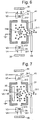
- Fig. 6 and Fig. 7 are configuration diagrams of conventional general EI ion sources. Although an example case where positive ions are analyzed is described here, even in the case where negative ions are to be analyzed, a basic operation is the same except that the polarities of voltages are reversed.
- a box-like ionization chamber 31 installed inside of a vacuum chamber (not illustrated) maintained at high vacuum has, formed therein: a sample introduction port 314 through which a sample gas is supplied; an ion emission port 311 from which ions are emitted; an electron introduction port 312 through which thermal electrons are introduced; and an electron discharge port 313 from which the thermal electrons are discharged.
- a filament 34 housed in a filament chamber 341 is arranged on the outer side of the electron introduction port 312. When a heating current If is supplied to the filament 34 from a heating current source (not illustrated), the temperature of the filament 34 rises, and thermal electrons are emitted from the surface of the filament 34.
- a counter filament 35 housed in a filament chamber 351 is arranged as a trap electrode on the outer side of the electron discharge port 313.
- a voltage V1 of, for example, -70 [V] is applied to the filament 34.
- a voltage V2 of, for example, -71 [V], which is slightly lower than the voltage V1, is applied to the filament chamber 341.
- a positive voltage V4 of, for example, approximately +10 [V] is applied to the counter filament 35.
- the ionization chamber 31 has a ground potential (0 [V]).
- the thermal electrons produced from the filament 34 are accelerated by a potential difference (-71 [V] ⁇ 0 [V]) between the filament chamber 341 and the ionization chamber 31, and are introduced into the ionization chamber 31 through the electron introduction port 312.
- the sample gas is introduced into the ionization chamber 31 from the sample introduction port 314.
- the electrons are attracted by the positive voltage V4 applied to the counter filament 35 to reach the counter filament 35, and a trap current Ib flows in the counter filament 35.
- the number of electrons trapped by the counter filament 35 depends on the number of electrons emitted from the filament 34.
- a control circuit (not illustrated) controls the heating current If such that the trap current Ib has a predetermined value. This makes the amount of thermal electrons produced from the filament 34 substantially constant, so that stable ionization is achieved in the ionization chamber 31.
- a pair of magnets 38 are installed on the outer sides of the filament 34 and the counter filament 35, and the pair of magnets 38 form a magnetic field inside and around the ionization chamber 31. Due to this magnetic field, the thermal electrons produced from the filament 34 and passing through the inside of the ionization chamber 31 toward the counter filament 35 fly on spirally whirling trajectories. Consequently, compared with the case where the electrons simply linearly fly, chances of contact between the electrons and the sample molecules increase, whereby the ionization efficiency can be enhanced.
- sample-derived ions are produced in the ionization chamber 31 in such a manner as described above.
- the sample-derived ions thus produced are emitted to the outside of the ionization chamber 31 through the ion emission port 311 to be used for mass spectrometry.
- a mechanism for the ion emission is different between Fig. 6 and Fig. 7 .
- a negative DC voltage V5 is applied to an extraction electrode 41 arranged on the outer side of the ion emission port 311.
- An electric field formed by a potential difference between the extraction electrode 41 and the ionization chamber 31 intrudes into the ionization chamber 31 through the ion emission port 311. Due to an action of this electric field, the ions produced in the ionization chamber 31 are extracted rightward in Fig. 6 (this operation is hereinafter referred to as an "extracting mode"), and are sent to a mass analyzer (not illustrated) such as a quadrupole mass filter.
- a repeller electrode 32 is arranged inside of the ionization chamber 31 and at a position opposed to the ion emission port 311, and a positive DC voltage V6 is applied to the repeller electrode 32. Due to an action of an electric field thus formed, the ions produced in the ionization chamber 31 are repelled rightward in Fig. 7 (this operation is hereinafter referred to as a "repelling mode"), are caused to pass through the ion emission port 311, and are sent to a mass analyzer (not illustrated). In some cases, both the ion repelling action of the repeller electrode 32 and the ion extracting action of the extraction electrode 41 are used.
- ions produced in a region around a central part of the ionization chamber 31 receive sufficient energy to move toward the ion emission port 311 and are sent out from the ion emission port 311, whereas ions produced around the corners on the ion emission port 311 side in the ionization chamber 31 less easily pass through the ion emission port 311 and most of the ions disappear upon contacting a wall surface of the ionization chamber 31 around the ion emission port 311.
- ions produced near the electron introduction port 312 and the electron discharge port 313 easily flow out through the electron introduction port 312 and the electron discharge port 313.
- the repelling mode only the ions produced in a relatively narrow region around the center of the ionization chamber 31 can be mainly used for mass spectrometry, and it is difficult to achieve high analysis sensitivity.
- the electric field that is formed outside of the ionization chamber 31 by the voltage applied to the extraction electrode 41 intrudes into the ionization chamber 31 through the ion emission port 311, and the ions are extracted by the extracting electric field thus formed.
- the extracting electric field that intrudes through the ion emission port 311 reaches even a region around the center of the ionization chamber 31, and hence the ions produced around the center of the ionization chamber 31 are favorably extracted from the ionization chamber 31.
- the electric field around the ion emission port 311 near the extraction electrode 41 is strong, and hence, compared with the repelling mode described above, a larger amount of the ions produced around the corners on the ion emission port 311 side in the ionization chamber 31 can be extracted. Accordingly, compared with the repelling mode, the extracting mode can more efficiently send out the ions produced in the ionization chamber 31 from the ion emission port 311, and is more advantageous to enhancement of the analysis sensitivity.
- the extracting electric field less easily reaches a region around the electron introduction port 312 and a region around the electron discharge port 313 in the ionization chamber 31, and hence the ions produced around these ports may flow out through the electron introduction port 312 and the electron discharge port 313.
- ion leakage preventing electrodes each including an opening that allows passing of electrons are respectively arranged between the filament 34 and the electron introduction port 312 and between the electron discharge port 313 and the counter filament 35, and a predetermined voltage is applied to each ion leakage preventing electrode such that an electric field whose gradient becomes steeper for the ions from each of the electron introduction port 312 and the electron discharge port 313 toward the ion leakage preventing electrode is formed. Consequently, the ions that are about to flow to the outside from the electron introduction port 312 and the electron discharge port 313 are returned to the inside of the ionization chamber 31, whereby an ion loss can be suppressed.
- the ionization apparatus described in Patent Literature 1 is further advantageous to enhancement of the analysis sensitivity.
- the extracting mode is more advantageous than the repelling mode in terms of achieving high sensitivity.
- the extracting mode is more disadvantageous than the repelling mode in terms of achieving the stability of the sensitivity.
- the potential gradient for moving the ions is given by the intrusion of the electric field formed by the voltage applied to the extraction electrode 41 arranged outside of the ionization chamber 31, and hence the potential gradient around the center of the ionization chamber 31 is gentler than that of the electric field that is formed in the ionization chamber 31 in the repelling mode.
- a charge-up phenomenon may occur in the ionization chamber 31, which is made of a conductor, so that the state of the electric field formed in the ionization chamber 31 changes.
- the potential gradient in the ionization chamber 31 is gentler, influences of such a change in electric field due to, so to speak, disturbance are larger.
- the extracting mode and the repelling mode As described above, comparing the extracting mode and the repelling mode with each other, the former is more advantageous in terms of high sensitivity but inferior in terms of stable sensitivity, whereas the latter is superior in terms of stable sensitivity but has relatively low sensitivity.
- the extracting mode and the repelling mode have advantages and disadvantages, and it is difficult to stably maintain high sensitivity. This also applies to the combination use of the extracting mode and the repelling mode. This is because optimal values of the voltage applied to the repeller electrode 32 and the voltage applied to the extraction electrode 41 are not the same between when high sensitivity is achieved and when the stability of the sensitivity is achieved.
- An object of the present invention which has been made in order to solve the above-mentioned problems, is to provide an ionization apparatus capable of sending out ions produced in an ionization chamber to the subsequent stage with as low a loss as possible, minimizing influences of a charge-up phenomenon that occurs along with long-term use of the apparatus, and thus achieving both high analysis sensitivity and high stability of the sensitivity.
- the present invention provides an ionization apparatus for ionizing predetermined sample molecules or atoms, the ionization apparatus including:
- sample molecules or atoms in a sample gas introduced into the ionization chamber contact thermal electrons, or the sample molecules or atoms react chemically with buffer ions produced by contact between a buffer gas contained in the sample gas or a separately supplied buffer gas and the thermal electrons, whereby the sample molecules or atoms are ionized.
- the sample-derived ions thus produced in the ionization chamber move toward the ion emission port due to an action of the repelling electric field that is formed in the ionization chamber by applying a predetermined voltage to the repeller electrode that is arranged inside of the ionization chamber so as to be opposed to the ion emission port.
- the sample-derived ions are sent out from the ion emission port in the repelling mode.
- the focusing electric field formed by applying a predetermined voltage to the ion focusing electrode arranged outside of the ionization chamber intrudes into the ionization chamber through the electron introduction port and/or the electron discharge port, and the focusing electric field gives a force to the ions such that the ions diffusing in directions toward the electron introduction port and the electron discharge port are focused toward a central part of the ionization chamber.
- the ion emission port is provided such that the ions are emitted in a direction substantially orthogonal to a direction in which the thermal electrons are introduced into the ionization chamber through the electron introduction port.
- the direction in which the focusing electric field pushes the ions in the ionization chamber is a direction substantially orthogonal to the direction in which the repelling electric field repels the ions.
- the combined force of the force of the repelling electric field and the force of the focusing electric field is given to the ions at positions relatively close to the electron introduction port and the electron discharge port in the ionization chamber. Consequently, the ions move so as to be focused around the central axis of the ion flow while travelling toward the ion emission port.
- the ions that will otherwise contact a wall or the like of the ionization chamber around the ion emission port and disappear in the state where only the repelling electric field acts on the ions can more easily pass through the ion emission port, so that a larger amount of ions can be sent to the subsequent stage.
- the ions are sent out from the ion emission port using the repelling electric field which is less easily influenced by disturbance such as a charge-up phenomenon, and further the potential gradient of the focusing electric field that intrudes into the ionization chamber through the electron introduction port and the electron discharge port is also less easily influenced by the charge-up phenomenon around the ion emission port.
- the trajectories of the sample-derived ions less easily change when the ions are sent out through the ion emission port, so that an ion low-loss state can be maintained.
- the ionization apparatus according to the present invention used as an ion source of a mass spectrometer, high analysis sensitivity can be achieved, and such high analysis sensitivity can be maintained even in long-term use of the apparatus.
- the ionization apparatus may further include a voltage applying unit for applying a DC voltage Vr having the same polarity as that of the sample-derived ions, to the repeller electrode and for applying a DC voltage Vs having the same polarity as that of the sample-derived ions, to the ion focusing electrode, the DC voltage Vr may be between 1 and 20 [V] and more preferably 1 and 8 [V], and the DC voltage Vs may be between 5 and 50 [V] and more preferably 5 and 20 [V]. Appropriate values for the applied voltages may be determined in accordance with the sizes and distances of the ionization chamber and other components.
- the ions produced in the ionization chamber are led to the ion emission port, and are sent out to the subsequent stage through the ion emission port. Consequently, an ion loss can be suppressed compared with an ionization apparatus using the conventional repelling mode, and a larger amount of ions can be sent out from the ion emission port. In addition, even if the charge-up phenomenon occurs along with long-term use of the apparatus, a change in ion trajectories can be reduced.
- the ionization apparatus according to the present invention used as an ion source of a mass spectrometer, the amount of ions to be used for mass spectrometry increases, enhancement of the analysis sensitivity can be achieved, and such high sensitivity can be maintained over a long period.
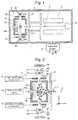
- Fig. 1 is a schematic configuration diagram of a mass spectrometer using the ion source according to the present embodiment
- Fig. 2 is a configuration diagram of the ion source according to the present embodiment.
- the same constituent elements as those in the conventional ion sources that have already been described with reference to Fig. 6 and Fig. 7 are denoted by the same reference signs.
- a mass spectrometer using the ion source of the present embodiment is described with reference to Fig. 1 .
- An ion source 3, an ion transport optical system 4, a quadrupole mass filter 5 as a mass analyzer, and an ion detector 6 are arranged inside of a chamber 1 that is evacuated by a vacuum pump 2.
- a sample gas that flows out from a column of a gas chromatograph (not illustrated) is communicated with a sample introduction port 314 of an ionization chamber 31, and sample molecules or atoms contained in the sample gas continuously supplied to the ionization chamber 31 are ionized upon contacting thermal electrons produced from a filament 34.
- the sample-derived ions thus produced are sent out from the ionization chamber 31 through an ion emission port 311, are focused by the ion transport optical system 4, and are introduced to a space in the long axis direction of the quadrupole mass filter 5.
- a voltage in which a DC voltage and an RF voltage are superposed is applied to the quadrupole mass filter 5 from a power source (not illustrated), and only ions having a mass-to-charge ratio m/z corresponding to the applied voltage pass through the space in the long axis direction and reach the ion detector 6 to be detected by the ion detector 6.
- the other unnecessary ionic species cannot pass through the space in the long axis direction of the quadrupole mass filter 5, and thus diverge and disappear on the way.
- a repeller electrode 32 is arranged at a position opposed to the ion emission port 311 in the ionization chamber 31, and a predetermined DC voltage is applied to the repeller electrode 32 from a repeller voltage source 73.
- Ion focusing electrodes 36 and 37 are respectively arranged between an electron introduction port 312 and a filament chamber 341 and between an electron discharge port 313 and a filament chamber 351.
- Each of the ion focusing electrodes 36 and 37 is, for example, a ring-like conductor including an electron pass opening having an inner diameter that is substantially the same as or slightly smaller than the inner diameter of each of the electron introduction port 312 and the electron discharge port 313.
- a predetermined DC voltage is applied to the ion focusing electrode 36 from a first ion focusing voltage source 71, and a predetermined DC voltage is applied to the ion focusing electrode 37 from another second ion focusing voltage source 72.
- independent voltages can be respectively applied to the two ion focusing electrodes 36 and 37.
- the applied voltages Vr and Vs are different depending on the size of the ionization chamber 31, the sizes of the electron introduction port 312 and the electron discharge port 313, the shapes of the ion focusing electrodes 36 and 37, distances from the electron introduction port 312 and the electron discharge port 313, and other factors. For example, appropriate values for the applied voltages Vr and Vs may be determined in advance based on simulations and experiments.
- the thermal electrons produced from the filament 34 enter the inside of the ionization chamber 31 through the electron introduction port 312, and move toward the electron discharge port 313 while each flying on a spiral trajectory due to an action of a magnetic field formed by a pair of magnets 38.
- the thermal electrons contact sample molecules or atoms on the way, the sample molecules or atoms are ionized.
- the ionization chamber 31 is grounded, and the positive DC voltage Vr of approximately 1 and 20 [V] is applied to the repeller electrode 32 as described above.
- Vr of approximately 1 and 20 [V]
- the thermal electrons each having a negative charge exist in an elongated region in the y-axis direction in the ionization chamber 31. Due to a space-charge effect produced by the electrons, the sample-derived ions each having the polarity opposite to that of the electrons tend to spread in the y-axis direction.
- the positive DC voltage Vs of approximately 5 and 50 [V] is applied to the ion focusing electrodes 36 and 37 respectively closely arranged on the outer sides of the electron introduction port 312 and the electron discharge port 313 as described above.
- an electric field is formed by a potential difference between the ion focusing electrodes 36 and 37 and the ionization chamber 31, and the electric field intrudes into the ionization chamber 31 through the electron introduction port 312 and the electron discharge port 313.
- This focusing electric field acts to push the ions in the y-axis negative direction (downward in Fig. 2 ) around the electron introduction port 312, and acts to push the ions in the y-axis positive direction (upward in Fig. 2 ) around the electron discharge port 313.
- this focusing electric field acts to confine the ions spreading in the y-axis positive-negative direction to a central part of the ionization chamber 31.
- the ions existing around the center of the ionization chamber 31 are pushed in the z-axis positive direction, and the ions existing at positions closer to the electron introduction port 312 and the electron discharge port 313 than the ions existing around the center are pushed toward the ion emission port 311 while approaching an ion optical axis C as the central axis of the ion flow.
- collisions of ions against a wall surface of the ionization chamber 31 around the ion emission port 311 as in the simple repelling mode can be avoided, and these ions can be sent out from the ion emission port 311.
- the amount of ions that can be sent out from the ion emission port 311 in other words, can be used for mass spectrometry is larger than that in the conventional repelling mode, and this leads to enhancement of the analysis sensitivity.
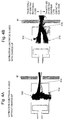
- Fig. 3A to Fig. 5B each illustrate a calculation result of ion trajectories according to a computer simulation, in order to verify a difference in ion trajectories between the ion source 3 of the present embodiment and the conventional ion sources (the repelling mode and the extracting mode).
- Fig. 3A and Fig. 3B are diagrams each illustrating a simulation result of ion trajectories at the time of using the repeller electrode (repelling mode) in the conventional ion source
- Fig. 4A and Fig. 4B are diagrams each illustrating a simulation result of ion trajectories at the time of using the extraction electrode (extracting mode) in the conventional ion source
- Fig. 3A to Fig. 5B each illustrate a calculation result of ion trajectories according to a computer simulation, in order to verify a difference in ion trajectories between the ion source 3 of the present embodiment and the conventional ion sources
- FIG. 5A and Fig. 5B are diagrams each illustrating a simulation result of ion trajectories in the ion source 3 of the present embodiment.
- Fig. 3A , Fig. 4A , and Fig. 5A each illustrate the case without a charge-up phenomenon
- Fig. 3B , Fig. 4B , and Fig. 5B each illustrate the case where a charge-up phenomenon occurs on the surface of the ionization chamber 31.
- constituent elements colored in solid black are constituent elements to which a positive DC voltage having the same polarity as that of the ions is applied.
- an upper half range illustrates the trajectories of ions that can reach the mass filter (not illustrated)
- a lower half range illustrates the trajectories of ions that disappear by colliding against the electrode or the like on the way.
- the ion trajectories in the ion source 3 of the present embodiment are almost the same even in the state where the charge-up phenomenon occurs.
- the trajectories of the thermal electrons produced from the filament 34 are also obtained together with the simulations of the ion trajectories. As a result, because the acceleration of the thermal electrons is high, it is verified that the trajectories of the thermal electrons are hardly influenced if the voltage Vs applied to each of the ion focusing electrodes 36 and 37 is within the above-mentioned range.
- the ion focusing electrodes 36 and 37 are respectively provided on the outer sides of the electron introduction port 312 and the electron discharge port 313, and this is desirable in terms of an ion focusing effect.
- the ion focusing electrode may be provided on the outer side of only any one of the two ports.
- different voltages can be applied to the two ion focusing electrodes 36 and 37, it is sufficient to apply the same voltage to the two electrodes in a normal operation.
- the ion source of the above-mentioned embodiment is an EI ion source
- the present invention can also be applied to a CI ion source.
- the present invention can also be used as ion sources of other apparatuses using ions such as an ion implantation apparatus.
Applications Claiming Priority (1)
| Application Number | Priority Date | Filing Date | Title |
|---|---|---|---|
| JP2015032833A JP6323362B2 (ja) | 2015-02-23 | 2015-02-23 | イオン化装置 |
Publications (1)
| Publication Number | Publication Date |
|---|---|
| EP3059756A1 true EP3059756A1 (fr) | 2016-08-24 |
Family
ID=55405220
Family Applications (1)
| Application Number | Title | Priority Date | Filing Date |
|---|---|---|---|
| EP16156663.3A Withdrawn EP3059756A1 (fr) | 2015-02-23 | 2016-02-22 | Appareil d'ionisation |
Country Status (4)
| Country | Link |
|---|---|
| US (1) | US9679755B2 (fr) |
| EP (1) | EP3059756A1 (fr) |
| JP (1) | JP6323362B2 (fr) |
| CN (1) | CN105914124B (fr) |
Cited By (2)
| Publication number | Priority date | Publication date | Assignee | Title |
|---|---|---|---|---|
| WO2018231631A1 (fr) * | 2017-06-13 | 2018-12-20 | Mks Instruments, Inc. | Source d'ions robuste |
| CN112599397A (zh) * | 2020-12-14 | 2021-04-02 | 兰州空间技术物理研究所 | 一种储存式离子源 |
Families Citing this family (18)
| Publication number | Priority date | Publication date | Assignee | Title |
|---|---|---|---|---|
| WO2018100621A1 (fr) * | 2016-11-29 | 2018-06-07 | 株式会社島津製作所 | Ioniseur et spectromètre de masse |
| JP6733819B2 (ja) | 2017-06-29 | 2020-08-05 | 株式会社島津製作所 | 四重極型質量分析装置 |
| KR101819534B1 (ko) | 2017-07-14 | 2018-03-02 | 한국기초과학지원연구원 | 이온화 소스 및 그를 포함하는 이차이온 질량분석기 |
| EP3688789A4 (fr) * | 2017-09-29 | 2021-09-29 | Perkinelmer Health Sciences Canada, Inc | Dispositifs et systèmes d'ionisation hors-axe |
| JP6908138B2 (ja) | 2018-02-06 | 2021-07-21 | 株式会社島津製作所 | イオン化装置及び質量分析装置 |
| CN108231529B (zh) * | 2018-03-09 | 2024-04-05 | 晓睿真空设备(嘉兴)有限公司 | 低压磁控阴极离子源 |
| US10622200B2 (en) * | 2018-05-18 | 2020-04-14 | Perkinelmer Health Sciences Canada, Inc. | Ionization sources and systems and methods using them |
| CN109212113B (zh) * | 2018-10-22 | 2023-05-12 | 南京国科精准医学科技有限公司 | 一种离子捕集气体分子分离方法及装置 |
| CN109406689B (zh) * | 2018-10-22 | 2023-05-12 | 南京国科精准医学科技有限公司 | 一种离子渗透气体分子分离方法及装置 |
| DE112019007323B4 (de) * | 2019-05-15 | 2023-08-03 | Shimadzu Corporation | Ionenanalysator |
| US11120966B2 (en) | 2019-09-03 | 2021-09-14 | Applied Materials, Inc. | System and method for improved beam current from an ion source |
| US11232925B2 (en) | 2019-09-03 | 2022-01-25 | Applied Materials, Inc. | System and method for improved beam current from an ion source |
| CN111146049A (zh) * | 2019-12-25 | 2020-05-12 | 兰州空间技术物理研究所 | 一种碳纳米管场发射阴极的小型离子源 |
| WO2021120539A1 (fr) * | 2020-06-08 | 2021-06-24 | 中国计量科学研究院 | Dispositif de source d'ionisation par impact d'électrons, procédé d'impact d'ionisation et procédé d'analyse de substance |
| US11581172B2 (en) | 2020-11-27 | 2023-02-14 | Shimadzu Corporation | Method for mass spectrometry and mass spectrometer |
| CN116997992A (zh) * | 2021-05-14 | 2023-11-03 | 株式会社岛津制作所 | 质量分析装置 |
| US11768176B2 (en) | 2022-01-06 | 2023-09-26 | Mks Instruments, Inc. | Ion source with gas delivery for high-fidelity analysis |
| US20240055247A1 (en) * | 2022-08-10 | 2024-02-15 | Exum Instruments | Off-axis ion extraction and shield glass assemblies for sample analysis systems |
Citations (5)
| Publication number | Priority date | Publication date | Assignee | Title |
|---|---|---|---|---|
| JP2005259482A (ja) | 2004-03-11 | 2005-09-22 | Shimadzu Corp | イオン化装置 |
| WO2012024468A2 (fr) * | 2010-08-19 | 2012-02-23 | Leco Corporation | Spectromètre de masse à temps de vol à source d'ionisation par impact électronique à accumulation |
| US20120205534A1 (en) * | 2011-02-14 | 2012-08-16 | The Massachusetts Institute Of Technology | Methods, apparatus, and system for mass spectrometry |
| WO2013163530A2 (fr) * | 2012-04-26 | 2013-10-31 | Leco Corporation | Source ionique de choc électronique à réponse rapide |
| WO2015153644A1 (fr) * | 2014-03-31 | 2015-10-08 | Leco Corporation | Cg-sm tof à limite de détection améliorée |
Family Cites Families (6)
| Publication number | Priority date | Publication date | Assignee | Title |
|---|---|---|---|---|
| DE10325579B4 (de) * | 2003-06-05 | 2007-10-11 | Bruker Daltonik Gmbh | Ionenfragmentierung durch Elektroneneinfang in linearen Ionenfallen |
| JP2010244903A (ja) * | 2009-04-07 | 2010-10-28 | Shimadzu Corp | 質量分析装置 |
| US9865422B2 (en) * | 2013-03-15 | 2018-01-09 | Nissin Ion Equipment Co., Ltd. | Plasma generator with at least one non-metallic component |
| US9881780B2 (en) * | 2013-04-23 | 2018-01-30 | Leco Corporation | Multi-reflecting mass spectrometer with high throughput |
| EP3094958B1 (fr) * | 2014-01-14 | 2023-07-12 | 908 Devices Inc. | Collecte d'échantillons dans des systèmes compacts de spectrométrie de masse |
| US9698000B2 (en) * | 2014-10-31 | 2017-07-04 | 908 Devices Inc. | Integrated mass spectrometry systems |
-
2015
- 2015-02-23 JP JP2015032833A patent/JP6323362B2/ja active Active
-
2016
- 2016-02-22 US US15/049,366 patent/US9679755B2/en not_active Expired - Fee Related
- 2016-02-22 EP EP16156663.3A patent/EP3059756A1/fr not_active Withdrawn
- 2016-02-23 CN CN201610099211.4A patent/CN105914124B/zh not_active Expired - Fee Related
Patent Citations (5)
| Publication number | Priority date | Publication date | Assignee | Title |
|---|---|---|---|---|
| JP2005259482A (ja) | 2004-03-11 | 2005-09-22 | Shimadzu Corp | イオン化装置 |
| WO2012024468A2 (fr) * | 2010-08-19 | 2012-02-23 | Leco Corporation | Spectromètre de masse à temps de vol à source d'ionisation par impact électronique à accumulation |
| US20120205534A1 (en) * | 2011-02-14 | 2012-08-16 | The Massachusetts Institute Of Technology | Methods, apparatus, and system for mass spectrometry |
| WO2013163530A2 (fr) * | 2012-04-26 | 2013-10-31 | Leco Corporation | Source ionique de choc électronique à réponse rapide |
| WO2015153644A1 (fr) * | 2014-03-31 | 2015-10-08 | Leco Corporation | Cg-sm tof à limite de détection améliorée |
Cited By (5)
| Publication number | Priority date | Publication date | Assignee | Title |
|---|---|---|---|---|
| WO2018231631A1 (fr) * | 2017-06-13 | 2018-12-20 | Mks Instruments, Inc. | Source d'ions robuste |
| US10541122B2 (en) | 2017-06-13 | 2020-01-21 | Mks Instruments, Inc. | Robust ion source |
| TWI776904B (zh) * | 2017-06-13 | 2022-09-11 | 美商Mks儀器股份有限公司 | 強健型離子源、質譜儀系統及使用離子源以產生用於質譜儀的離子的方法 |
| CN112599397A (zh) * | 2020-12-14 | 2021-04-02 | 兰州空间技术物理研究所 | 一种储存式离子源 |
| CN112599397B (zh) * | 2020-12-14 | 2023-06-06 | 兰州空间技术物理研究所 | 一种储存式离子源 |
Also Published As
| Publication number | Publication date |
|---|---|
| US20160247669A1 (en) | 2016-08-25 |
| JP6323362B2 (ja) | 2018-05-16 |
| US9679755B2 (en) | 2017-06-13 |
| CN105914124A (zh) | 2016-08-31 |
| CN105914124B (zh) | 2018-07-10 |
| JP2016157523A (ja) | 2016-09-01 |
Similar Documents
| Publication | Publication Date | Title |
|---|---|---|
| US9679755B2 (en) | Ionization apparatus | |
| JP5792203B2 (ja) | イオンを抑制させたプラズマ質量分析器 | |
| US8324565B2 (en) | Ion funnel for mass spectrometry | |
| US7372042B2 (en) | Lens device for introducing a second ion beam into a primary ion path | |
| JP4384542B2 (ja) | 質量分析装置 | |
| US10176977B2 (en) | Ion source for soft electron ionization and related systems and methods | |
| JP6423615B2 (ja) | 軸方向磁気イオン源及び関連するイオン化方法 | |
| JP6666919B2 (ja) | 電子誘起解離デバイスおよび方法 | |
| JP6292722B2 (ja) | 質量分析のためのイオンガイド | |
| US11495447B2 (en) | Ionizer and mass spectrometer | |
| US10541122B2 (en) | Robust ion source | |
| JP4232662B2 (ja) | イオン化装置 | |
| US10290485B2 (en) | Fourier transform ion cyclotron resonance mass spectrometry | |
| KR102215830B1 (ko) | 이온을 선택하기 위해 가스 혼합물을 사용하는 시스템 및 방법 | |
| CN113496866A (zh) | 逆流均匀场离子迁移率谱仪 | |
| CN110612595B (zh) | 离子检测装置及质谱分析装置 | |
| JP2020535622A (ja) | 軸外イオン化デバイスおよびシステム | |
| US20230245878A1 (en) | Mass spectrometer | |
| CN114245931A (zh) | 电离源以及使用电离源的方法和系统 | |
| KR20110071320A (ko) | 이온 주입기, 이를 포함하는 질량 분석기 및 이를 이용한 이온 집속 방법 |
Legal Events
| Date | Code | Title | Description |
|---|---|---|---|
| PUAI | Public reference made under article 153(3) epc to a published international application that has entered the european phase |
Free format text: ORIGINAL CODE: 0009012 |
|
| AK | Designated contracting states |
Kind code of ref document: A1 Designated state(s): AL AT BE BG CH CY CZ DE DK EE ES FI FR GB GR HR HU IE IS IT LI LT LU LV MC MK MT NL NO PL PT RO RS SE SI SK SM TR |
|
| AX | Request for extension of the european patent |
Extension state: BA ME |
|
| 17P | Request for examination filed |
Effective date: 20170116 |
|
| RBV | Designated contracting states (corrected) |
Designated state(s): AL AT BE BG CH CY CZ DE DK EE ES FI FR GB GR HR HU IE IS IT LI LT LU LV MC MK MT NL NO PL PT RO RS SE SI SK SM TR |
|
| 17Q | First examination report despatched |
Effective date: 20191010 |
|
| STAA | Information on the status of an ep patent application or granted ep patent |
Free format text: STATUS: THE APPLICATION HAS BEEN WITHDRAWN |
|
| 18W | Application withdrawn |
Effective date: 20191218 |