EP3059486B1 - Unterstützungsstruktur, player und mobile vorrichtung damit - Google Patents
Unterstützungsstruktur, player und mobile vorrichtung damit Download PDFInfo
- Publication number
- EP3059486B1 EP3059486B1 EP14853803.6A EP14853803A EP3059486B1 EP 3059486 B1 EP3059486 B1 EP 3059486B1 EP 14853803 A EP14853803 A EP 14853803A EP 3059486 B1 EP3059486 B1 EP 3059486B1
- Authority
- EP
- European Patent Office
- Prior art keywords
- player
- supporting structure
- stationary shafts
- stoppers
- stopper
- Prior art date
- Legal status (The legal status is an assumption and is not a legal conclusion. Google has not performed a legal analysis and makes no representation as to the accuracy of the status listed.)
- Not-in-force
Links
Images




Classifications
-
- B—PERFORMING OPERATIONS; TRANSPORTING
- B62—LAND VEHICLES FOR TRAVELLING OTHERWISE THAN ON RAILS
- B62B—HAND-PROPELLED VEHICLES, e.g. HAND CARTS OR PERAMBULATORS; SLEDGES
- B62B3/00—Hand carts having more than one axis carrying transport wheels; Steering devices therefor; Equipment therefor
- B62B3/14—Hand carts having more than one axis carrying transport wheels; Steering devices therefor; Equipment therefor characterised by provisions for nesting or stacking, e.g. shopping trolleys
- B62B3/1408—Display devices mounted on it, e.g. advertisement displays
- B62B3/1416—Display devices mounted on it, e.g. advertisement displays mounted on the handle
-
- B—PERFORMING OPERATIONS; TRANSPORTING
- B62—LAND VEHICLES FOR TRAVELLING OTHERWISE THAN ON RAILS
- B62B—HAND-PROPELLED VEHICLES, e.g. HAND CARTS OR PERAMBULATORS; SLEDGES
- B62B5/00—Accessories or details specially adapted for hand carts
-
- B—PERFORMING OPERATIONS; TRANSPORTING
- B62—LAND VEHICLES FOR TRAVELLING OTHERWISE THAN ON RAILS
- B62B—HAND-PROPELLED VEHICLES, e.g. HAND CARTS OR PERAMBULATORS; SLEDGES
- B62B3/00—Hand carts having more than one axis carrying transport wheels; Steering devices therefor; Equipment therefor
- B62B3/14—Hand carts having more than one axis carrying transport wheels; Steering devices therefor; Equipment therefor characterised by provisions for nesting or stacking, e.g. shopping trolleys
- B62B3/1408—Display devices mounted on it, e.g. advertisement displays
- B62B3/1424—Electronic display devices
-
- F—MECHANICAL ENGINEERING; LIGHTING; HEATING; WEAPONS; BLASTING
- F16—ENGINEERING ELEMENTS AND UNITS; GENERAL MEASURES FOR PRODUCING AND MAINTAINING EFFECTIVE FUNCTIONING OF MACHINES OR INSTALLATIONS; THERMAL INSULATION IN GENERAL
- F16M—FRAMES, CASINGS OR BEDS OF ENGINES, MACHINES OR APPARATUS, NOT SPECIFIC TO ENGINES, MACHINES OR APPARATUS PROVIDED FOR ELSEWHERE; STANDS; SUPPORTS
- F16M11/00—Stands or trestles as supports for apparatus or articles placed thereon ; Stands for scientific apparatus such as gravitational force meters
- F16M11/02—Heads
- F16M11/04—Means for attachment of apparatus; Means allowing adjustment of the apparatus relatively to the stand
- F16M11/06—Means for attachment of apparatus; Means allowing adjustment of the apparatus relatively to the stand allowing pivoting
- F16M11/10—Means for attachment of apparatus; Means allowing adjustment of the apparatus relatively to the stand allowing pivoting around a horizontal axis
-
- F—MECHANICAL ENGINEERING; LIGHTING; HEATING; WEAPONS; BLASTING
- F16—ENGINEERING ELEMENTS AND UNITS; GENERAL MEASURES FOR PRODUCING AND MAINTAINING EFFECTIVE FUNCTIONING OF MACHINES OR INSTALLATIONS; THERMAL INSULATION IN GENERAL
- F16M—FRAMES, CASINGS OR BEDS OF ENGINES, MACHINES OR APPARATUS, NOT SPECIFIC TO ENGINES, MACHINES OR APPARATUS PROVIDED FOR ELSEWHERE; STANDS; SUPPORTS
- F16M11/00—Stands or trestles as supports for apparatus or articles placed thereon ; Stands for scientific apparatus such as gravitational force meters
- F16M11/20—Undercarriages with or without wheels
- F16M11/22—Undercarriages with or without wheels with approximately constant height, e.g. with constant length of column or of legs
-
- F—MECHANICAL ENGINEERING; LIGHTING; HEATING; WEAPONS; BLASTING
- F16—ENGINEERING ELEMENTS AND UNITS; GENERAL MEASURES FOR PRODUCING AND MAINTAINING EFFECTIVE FUNCTIONING OF MACHINES OR INSTALLATIONS; THERMAL INSULATION IN GENERAL
- F16M—FRAMES, CASINGS OR BEDS OF ENGINES, MACHINES OR APPARATUS, NOT SPECIFIC TO ENGINES, MACHINES OR APPARATUS PROVIDED FOR ELSEWHERE; STANDS; SUPPORTS
- F16M11/00—Stands or trestles as supports for apparatus or articles placed thereon ; Stands for scientific apparatus such as gravitational force meters
- F16M11/42—Stands or trestles as supports for apparatus or articles placed thereon ; Stands for scientific apparatus such as gravitational force meters with arrangement for propelling the support stands on wheels
-
- B—PERFORMING OPERATIONS; TRANSPORTING
- B62—LAND VEHICLES FOR TRAVELLING OTHERWISE THAN ON RAILS
- B62B—HAND-PROPELLED VEHICLES, e.g. HAND CARTS OR PERAMBULATORS; SLEDGES
- B62B2202/00—Indexing codes relating to type or characteristics of transported articles
- B62B2202/56—Computers; Screens
Definitions
- the present invention relates to a supporting structure, in particular to a supporting structure being capable of adjusting angles of a supported article, a player employing the supporting structure and a mobile device employing the player.
- Air travel has become more and more common. Since airport area is too large, passengers may have to ask for directions several times before reaching a registration desk. In this case, a trolley with a multimedia player for broadcasting and guiding emerges, which provides convenience for users.
- various problems may arise when passengers use the trolley, for example: some passengers may use the player as a temporary dining-table for a momentary convenience and put drink and foods on the surface of the player's display screen, and some passengers may use the player as a child seat to allow children sitting on the player.
- overall assembling process and technology of a trolley's frame are not yet perfect, a stress is easily to generate in the interior of the frame. This stress exists for long, which may undermine the overall structure of the player. Such phenomenon is likely to cause damage to the trolley's player, and may have a safety problem.
- a typical supporting structure is shown in US2010/0051761 .
- An object of the present invention is to provide a supporting structure capable of adjusting angles of a supported member.
- the supporting structure comprises a support body, stationary shafts and stoppers disposed at opposite ends of said support body and being coaxial with the stationary shafts, wherein each of said stationary shafts is provided with an arc-shaped notch matching with each of the stoppers circumferentially, so that the stoppers are rotatable about the stationary shafts along the arc-shaped notch, which causes the supported body to rotate about the stationary shaft, thereby allowing an installing angle of the supported body on a mobile device, such as trolleys, etc., to be set and adjusted to meet different needs of users for angles of the supported member.
- a mobile device such as trolleys, etc.
- the stopper comprises a stopper body and a stopper projection provided on an inner wall of the stopper body.
- the stoppers can rotate stably along the stationary shafts through cooperation of the stopper bodies and the stationary shafts.
- the stopper body is U-shaped.
- the U-shaped stopper body can facilitate a rotation of the stopper about the stationary shaft. Meanwhile, the bottom of the U-shaped stopper body can prevent foreign material from entering into the arc-shaped notch, and thus effectively avoid failure of the stopper's rotation about the stationary shafts due to entering of the foreign material into the arc-shaped notch.
- the fixed shaft comprises a shaft base and a shaft portion in a T-shaped connection with the shaft base, the arc-shaped notch is provided at an end of the shaft portion connected to the stationary shaft base.
- the shaft base and the shaft portion have a hollow structure, which reduces the weight of the supporting structure and saves makings.
- a central angle of the arc-shaped notch is an acute angle.
- the supported member may rotate about the stationary shafts within an acute angle range after installed on the supporting structure, so as to satisfy different needs of users for the orientation of the supported member.
- the outer diameter of the shaft portion is smaller than the inner diameter of an arc portion at the bottom of the stopper body. This may reduce the wear therebetween when the stoppers rotate about the stationary shafts, which causes the rotation of the stoppers more efficiently.
- support plates are disposed on the support body, and an end of the support plate is inserted into the interior of the stationary shafts. After the support body is installed on a movable device, it can prevent the internal structure of the support body from being damaged due to the internal stress of the movable device, which increases the strength of the support body and protect the same. Meanwhile, deformation of the mobile device due to its internal stress can be avoided.
- a player which comprises a player member and a supporting structure mentioned above.
- the player member comprises a multimedia player device and is disposed in the support body.
- the player member can rotate about the stationary shafts along with the stoppers, which provides convenience to users.
- a movable device which comprises a movable device body and a player mentioned above, stationary shafts of the supporting structure of the player are disposed on the movable device body.
- the player according to the invention can rotate about the stationary shafts so as to prevent the player from being damaged due to the improper use of users when the player can only be disposed horizontally, and meet different needs of users for the orientation of the player.
- Figs. 1 to 5 schematically show a supporting structure according to an embodiment of the present invention.
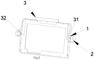
- the supporting structure comprises stoppers 1, stationary shafts 2 and a support body 3.
- the support body 3 may be formed as a rectangular frame.
- Support plates 31 are disposed at left and right sides of the support body 3 respectively.
- the support plates 31 are L-shaped.
- each of the support plates 31 is fixedly connected at one end with the support body and the other end thereof passes through a side plate of the support body 3 through a groove 32 on the side plate.
- the support plate 31 on the left of the structure is not shown for the clarity purpose.
- each of stoppers 1 comprises a stopper body 11 and a stopper projection 12.
- the stopper body 11 is U-shaped, and the stopper projection 12 is provided at the bottom of the inner wall of the stopper body 11.
- Two stoppers 1 are disposed on opposite sides of the support body 3 respectively. That is, two stopper bodies 11 of two stoppers 1 are fixedly connected to left and right side plates of the support body 3, respectively. Meanwhile, two stoppers 1 are disposed coaxially.
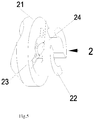
- each of the stationary shafts 2 comprises a shaft base 21 and a shaft portion 22 which are integrally connected with each other.
- the stationary shafts 2 are T-shaped along its longitudinal section.
- the shaft base 21 and the shaft portion 22 are formed to be cylindrical and with a hollow structure.
- An arc-shaped notch 23 is disposed circumferentially at an end of the shaft portion connected to the shaft base.
- the arc-shaped notch 23 and the stopper projection 12 are matched in shape and size, so that the stoppers 1 can rotate about the stationary shafts 2 along the arc-shaped notch 23.
- the outer diameter of the shaft portion 22 is smaller (such as 0.5mm) than the inner diameter of an arc portion at the bottom of the U-shaped stopper body, which can reduce the wear of the supporting structure and make the rotation of the stoppers around the stationary shaft 2 more efficient.
- a central angle of the arc-shaped notch 23 is an acute angle, so that a range of the rotational angle of the stoppers 1 around the stationary shafts 2 is 0 ° ⁇ 90 °. For example, as shown in Fig. 5 , the central angle of the curve notch 23 is 60 °, thus the range of the rotational angle of the stoppers 1 is 60°.
- An opening 24 is formed at the other end of the shaft portion not connected to the shaft base 21 and is communicated with the arc-shaped notch 23, thereby facilitating the installation of the stoppers on the stationary shafts.
- the stationary shafts 2 may be disposed on a movable device and is coaxial with the stopper 1.
- the stopper 1 is positioned corresponding to the groove 32 so that one end of the support plate 32 is inserted into the hollow portion of the interior of the stationary shaft 2 when the stopper 1 is coupled with the stationary shaft 2.
- a player according to an embodiment of the invention comprises a supporting structure as described above, a player member 4 and a housing 5.
- the player member 4 comprises a conventional multimedia player, which is referred to as supported member.
- the player member 4 is disposed in the support body 3 of the supporting structure.
- the housing 5 is disposed outside the supporting structure. A hole is provided at a position where the housing 5 corresponds in position with the stopper 1 to accommodate the stopper and allow the installation of the stationary shaft.
- a movable device comprising a movable device body and a player mentioned above will be described below.
- the stationary shafts of the supporting structure of the player are disposed on the movable device body.
- trolley is described as an example of the movable device in the illustration of following embodiments. It will be understood for those skilled in the art that the embodiments of the invention will apply to any movable devices similar to the trolley.
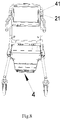
- the trolley comprises a trolley body 41 and a player mentioned above.
- the player is installed between the left and right frames of the trolley body 41, two shaft bodies 21 of the stationary shafts 2 on respective sides of the player are fixedly connected to the left and right frames of the trolley body 41 by welding or the like. Further, the player's stoppers 1 and the stationary shafts 2 are disposed coaxially, so that the player member 3 can rotate around the stationary shafts 2.
Landscapes
- Engineering & Computer Science (AREA)
- General Engineering & Computer Science (AREA)
- Mechanical Engineering (AREA)
- Chemical & Material Sciences (AREA)
- Combustion & Propulsion (AREA)
- Transportation (AREA)
- Casings For Electric Apparatus (AREA)
- Pivots And Pivotal Connections (AREA)
- Toys (AREA)
- Handcart (AREA)
Claims (7)
- Stützstruktur, umfassend einem Stützkörper (3), stationäre Wellen (2) und Anschläge (1), die an gegenüberliegenden Enden des Stützkörpers (3) und auf einer gleichen Achse wie die stationären Wellen (2) angeordnet sind, wobei jede der stationären Wellen (2) mit einer bogenförmigen Kerbe (23) versehen ist, die an einem jeweiligen Anschlag der Anschläge (1) umfangsseitig angepasst ist, so dass die Anschläge (1) um die Stationäre Wellen (2) entlang der bogenförmigen Kerbe (23) drehbar sind, dadurch gekennzeichnet, dass jeder der Anschläge (1) einen U-förmigen Anschlagkörper (11) und einen Anschlagvorsprung (12) umfasst, der an einer Innenwand des Anschlagkörpers (11) vorgesehen ist, jede der stationären Wellen (2) eine Wellenbasis (21) und einen Wellenabschnitt (22) umfasst, der T-förmig mit der Wellenbasis (21) verbunden ist, die bogenförmige Kerbe (23) an einem Ende des Wellenabschnitts (22) vorgesehen ist, das mit der Wellenbasis (21) verbunden ist.
- Stützstruktur nach Anspruch 1, wobei die Wellenbasis (21) und der Wellenabschnitt (22) eine hohle Struktur aufweisen.
- Stützstruktur nach Anspruch 1, wobei ein zentraler Winkel der bogenförmigen Kerbe (23) ein spitzer Winkel ist.
- Stützstruktur nach Anspruch 2, wobei der Außendurchmesser des Wellenabschnitts (22) kleiner ist als der Innendurchmesser eines Bogenabschnitts am Boden des Anschlagkörpers (11).
- Stützstruktur nach Anspruch 2, wobei Stützplatten (31) an dem Stützkörper (3) angeordnet sind, und ein Ende der Stützplatten (31) in das Innere der stationären Wellen (2) eingesetzt ist.
- Spieler, umfassend ein Spielerelement (4) und eine Stützstruktur nach einem der Ansprüche 1 bis 5, wobei das Spielerelement eine Multimedia-Spielervorrichtung umfasst und in dem Stützkörper (3) angeordnet ist.
- Bewegliche Vorrichtung, umfassend einen beweglichen Vorrichtungskörper und den Spieler nach Anspruch 6, wobei die stationären Wellen (2) der Stützstruktur des Spielers auf dem beweglichen Vorrichtungskörper angeordnet sind.
Applications Claiming Priority (2)
| Application Number | Priority Date | Filing Date | Title |
|---|---|---|---|
| CN201320640581.6U CN203500788U (zh) | 2013-10-16 | 2013-10-16 | 支撑结构、播放器及使用该播放器的移动设备 |
| PCT/CN2014/085176 WO2015055050A1 (zh) | 2013-10-16 | 2014-08-26 | 支撑结构、播放器及使用该播放器的移动设备 |
Publications (3)
| Publication Number | Publication Date |
|---|---|
| EP3059486A1 EP3059486A1 (de) | 2016-08-24 |
| EP3059486A4 EP3059486A4 (de) | 2017-06-14 |
| EP3059486B1 true EP3059486B1 (de) | 2019-02-06 |
Family
ID=50331764
Family Applications (1)
| Application Number | Title | Priority Date | Filing Date |
|---|---|---|---|
| EP14853803.6A Not-in-force EP3059486B1 (de) | 2013-10-16 | 2014-08-26 | Unterstützungsstruktur, player und mobile vorrichtung damit |
Country Status (7)
| Country | Link |
|---|---|
| US (1) | US20160272231A1 (de) |
| EP (1) | EP3059486B1 (de) |
| JP (1) | JP2017500497A (de) |
| KR (1) | KR101827909B1 (de) |
| CN (1) | CN203500788U (de) |
| HK (1) | HK1222696A1 (de) |
| WO (1) | WO2015055050A1 (de) |
Families Citing this family (3)
| Publication number | Priority date | Publication date | Assignee | Title |
|---|---|---|---|---|
| CN203103711U (zh) * | 2013-01-10 | 2013-07-31 | 无锡知谷网络科技有限公司 | 电连接器及移动设备 |
| CN203500788U (zh) * | 2013-10-16 | 2014-03-26 | 无锡知谷网络科技有限公司 | 支撑结构、播放器及使用该播放器的移动设备 |
| CN111409678B (zh) * | 2020-05-06 | 2024-05-31 | 苏州佳智彩光电科技有限公司 | 一种便于简易操作的Tray盘搬运上料小车 |
Family Cites Families (18)
| Publication number | Priority date | Publication date | Assignee | Title |
|---|---|---|---|---|
| JPS5840639Y2 (ja) * | 1979-11-07 | 1983-09-13 | ホリエ電機株式会社 | 電気器具の脚取付装置 |
| JPS63135991A (ja) * | 1986-11-27 | 1988-06-08 | 日本精機株式会社 | 手押し車用情報表示装置 |
| JPH0740792Y2 (ja) * | 1989-01-26 | 1995-09-20 | 松下電工株式会社 | タスクアームのベース部 |
| JPH02274657A (ja) * | 1989-04-18 | 1990-11-08 | Kazunori Okada | 買物情報提供カート |
| JP3459727B2 (ja) * | 1996-06-24 | 2003-10-27 | シャープ株式会社 | チルト機構 |
| JP2002372036A (ja) * | 2001-06-15 | 2002-12-26 | Matsushita Electric Ind Co Ltd | 角度調整装置 |
| KR200348250Y1 (ko) * | 2004-01-16 | 2004-04-28 | 박병근 | 각도 조절이 가능한 핸드폰 진열대 |
| US20060007191A1 (en) * | 2004-06-03 | 2006-01-12 | International Business Machines Corporation | System and method for adjusting a screen |
| CN2911878Y (zh) * | 2006-05-23 | 2007-06-13 | 天津三星电子显示器有限公司 | 一种可调整角度的支架 |
| EP1887273A3 (de) * | 2006-08-10 | 2009-06-10 | Samsung Electronics Co., Ltd. | Trägvorrichtung für Anzeigegeräte und Anzeigegerät damit |
| JP4799323B2 (ja) * | 2006-08-31 | 2011-10-26 | 富士通株式会社 | 買物支援プログラム、ショッピングカート、および買物支援方法 |
| CN101660650B (zh) * | 2008-08-26 | 2012-03-28 | 鸿富锦精密工业(深圳)有限公司 | 支撑机构及采用该支撑机构的电子装置 |
| JP5681894B2 (ja) * | 2010-08-31 | 2015-03-11 | パナソニックIpマネジメント株式会社 | 電子装置 |
| CN201882122U (zh) * | 2010-11-19 | 2011-06-29 | 无锡知谷网络科技有限公司 | 一种可携带播放器的手推车 |
| JP2013075545A (ja) * | 2011-09-29 | 2013-04-25 | Jvc Kenwood Corp | 携帯電子機器の取り付け構造 |
| CN203071613U (zh) * | 2013-01-10 | 2013-07-17 | 无锡知谷网络科技有限公司 | 可充电的移动设备 |
| CN203103711U (zh) * | 2013-01-10 | 2013-07-31 | 无锡知谷网络科技有限公司 | 电连接器及移动设备 |
| CN203500788U (zh) * | 2013-10-16 | 2014-03-26 | 无锡知谷网络科技有限公司 | 支撑结构、播放器及使用该播放器的移动设备 |
-
2013
- 2013-10-16 CN CN201320640581.6U patent/CN203500788U/zh not_active Expired - Lifetime
-
2014
- 2014-08-26 HK HK16110742.2A patent/HK1222696A1/en unknown
- 2014-08-26 WO PCT/CN2014/085176 patent/WO2015055050A1/zh not_active Ceased
- 2014-08-26 US US15/029,412 patent/US20160272231A1/en not_active Abandoned
- 2014-08-26 EP EP14853803.6A patent/EP3059486B1/de not_active Not-in-force
- 2014-08-26 JP JP2016524115A patent/JP2017500497A/ja not_active Ceased
- 2014-08-26 KR KR1020167012473A patent/KR101827909B1/ko not_active Expired - Fee Related
Non-Patent Citations (1)
| Title |
|---|
| None * |
Also Published As
| Publication number | Publication date |
|---|---|
| CN203500788U (zh) | 2014-03-26 |
| KR20160070811A (ko) | 2016-06-20 |
| WO2015055050A1 (zh) | 2015-04-23 |
| JP2017500497A (ja) | 2017-01-05 |
| HK1222696A1 (en) | 2017-07-07 |
| EP3059486A1 (de) | 2016-08-24 |
| US20160272231A1 (en) | 2016-09-22 |
| EP3059486A4 (de) | 2017-06-14 |
| KR101827909B1 (ko) | 2018-03-22 |
Similar Documents
| Publication | Publication Date | Title |
|---|---|---|
| US9480326B2 (en) | Hand-wearable camera harness and method of assembling the hand-wearable camera harness | |
| EP3059486A1 (de) | Unterstützungsstruktur, player und mobile vorrichtung damit | |
| JP2013241765A5 (de) | ||
| EP3180246B1 (de) | Gepäckfach | |
| KR20160128349A (ko) | 카트 | |
| JP2008290638A (ja) | 双方向ローラ | |
| CA2545130A1 (en) | Paper roll and paper roll dispenser | |
| US9821652B2 (en) | Structure for opening and closing fuel filler opening | |
| EP2594456A3 (de) | Fahrzeuglenkungssystem | |
| CN110127031B (zh) | 一种折叠组件及无人机 | |
| US20110278119A1 (en) | Rotary damper mounting assembly and rotary damper apparatus | |
| US20120218770A1 (en) | Easily Maintainable Lamp Connection Device | |
| US20150040707A1 (en) | Reducer for vehicle | |
| CN204250385U (zh) | 一种硬式空中加油试验加油杆支撑机构 | |
| CN104827974A (zh) | 手套箱限位器及具有其的手套箱总成 | |
| KR20160131235A (ko) | 접이식 운반 카트 | |
| JP5714121B2 (ja) | キャスター | |
| US20130029820A1 (en) | Sleeve and multi-function printer | |
| US7624686B2 (en) | Permanent magnetic levitation bogie apparatus | |
| CN104149903A (zh) | 折叠车的把立收折锁紧机构 | |
| CN105417290A (zh) | 便于运输的电缆存放装置 | |
| CN211859321U (zh) | 电气开关设备的操作机构的滚轮支撑装置及电气开关设备 | |
| JP2015021550A (ja) | 転がり軸受 | |
| CN105752327B (zh) | 双圆锥滚子轴承定位的机架及无人直升机 | |
| CN204647017U (zh) | 组合轴承座 |
Legal Events
| Date | Code | Title | Description |
|---|---|---|---|
| PUAI | Public reference made under article 153(3) epc to a published international application that has entered the european phase |
Free format text: ORIGINAL CODE: 0009012 |
|
| 17P | Request for examination filed |
Effective date: 20160331 |
|
| AK | Designated contracting states |
Kind code of ref document: A1 Designated state(s): AL AT BE BG CH CY CZ DE DK EE ES FI FR GB GR HR HU IE IS IT LI LT LU LV MC MK MT NL NO PL PT RO RS SE SI SK SM TR |
|
| AX | Request for extension of the european patent |
Extension state: BA ME |
|
| RAP1 | Party data changed (applicant data changed or rights of an application transferred) |
Owner name: CHIGOO INTERACTIVE TECHNOLOGY CO., LTD. |
|
| RIN1 | Information on inventor provided before grant (corrected) |
Inventor name: PAN, CHUANRONG Inventor name: LAN, WEIJIAN Inventor name: CHEN, TAO Inventor name: YANG, YONG Inventor name: ZHOU, HUA Inventor name: HAN, RONG |
|
| DAX | Request for extension of the european patent (deleted) | ||
| A4 | Supplementary search report drawn up and despatched |
Effective date: 20170517 |
|
| RIC1 | Information provided on ipc code assigned before grant |
Ipc: F16M 11/10 20060101AFI20170511BHEP |
|
| REG | Reference to a national code |
Ref country code: HK Ref legal event code: DE Ref document number: 1222696 Country of ref document: HK |
|
| STAA | Information on the status of an ep patent application or granted ep patent |
Free format text: STATUS: EXAMINATION IS IN PROGRESS |
|
| 17Q | First examination report despatched |
Effective date: 20180221 |
|
| GRAP | Despatch of communication of intention to grant a patent |
Free format text: ORIGINAL CODE: EPIDOSNIGR1 |
|
| STAA | Information on the status of an ep patent application or granted ep patent |
Free format text: STATUS: GRANT OF PATENT IS INTENDED |
|
| INTG | Intention to grant announced |
Effective date: 20180815 |
|
| GRAS | Grant fee paid |
Free format text: ORIGINAL CODE: EPIDOSNIGR3 |
|
| GRAA | (expected) grant |
Free format text: ORIGINAL CODE: 0009210 |
|
| STAA | Information on the status of an ep patent application or granted ep patent |
Free format text: STATUS: THE PATENT HAS BEEN GRANTED |
|
| AK | Designated contracting states |
Kind code of ref document: B1 Designated state(s): AL AT BE BG CH CY CZ DE DK EE ES FI FR GB GR HR HU IE IS IT LI LT LU LV MC MK MT NL NO PL PT RO RS SE SI SK SM TR |
|
| REG | Reference to a national code |
Ref country code: GB Ref legal event code: FG4D |
|
| REG | Reference to a national code |
Ref country code: CH Ref legal event code: EP Ref country code: AT Ref legal event code: REF Ref document number: 1095133 Country of ref document: AT Kind code of ref document: T Effective date: 20190215 |
|
| REG | Reference to a national code |
Ref country code: DE Ref legal event code: R096 Ref document number: 602014040857 Country of ref document: DE |
|
| REG | Reference to a national code |
Ref country code: IE Ref legal event code: FG4D |
|
| REG | Reference to a national code |
Ref country code: NL Ref legal event code: MP Effective date: 20190206 |
|
| REG | Reference to a national code |
Ref country code: LT Ref legal event code: MG4D |
|
| PG25 | Lapsed in a contracting state [announced via postgrant information from national office to epo] |
Ref country code: SE Free format text: LAPSE BECAUSE OF FAILURE TO SUBMIT A TRANSLATION OF THE DESCRIPTION OR TO PAY THE FEE WITHIN THE PRESCRIBED TIME-LIMIT Effective date: 20190206 Ref country code: PT Free format text: LAPSE BECAUSE OF FAILURE TO SUBMIT A TRANSLATION OF THE DESCRIPTION OR TO PAY THE FEE WITHIN THE PRESCRIBED TIME-LIMIT Effective date: 20190606 Ref country code: NL Free format text: LAPSE BECAUSE OF FAILURE TO SUBMIT A TRANSLATION OF THE DESCRIPTION OR TO PAY THE FEE WITHIN THE PRESCRIBED TIME-LIMIT Effective date: 20190206 Ref country code: LT Free format text: LAPSE BECAUSE OF FAILURE TO SUBMIT A TRANSLATION OF THE DESCRIPTION OR TO PAY THE FEE WITHIN THE PRESCRIBED TIME-LIMIT Effective date: 20190206 Ref country code: NO Free format text: LAPSE BECAUSE OF FAILURE TO SUBMIT A TRANSLATION OF THE DESCRIPTION OR TO PAY THE FEE WITHIN THE PRESCRIBED TIME-LIMIT Effective date: 20190506 Ref country code: FI Free format text: LAPSE BECAUSE OF FAILURE TO SUBMIT A TRANSLATION OF THE DESCRIPTION OR TO PAY THE FEE WITHIN THE PRESCRIBED TIME-LIMIT Effective date: 20190206 |
|
| REG | Reference to a national code |
Ref country code: AT Ref legal event code: MK05 Ref document number: 1095133 Country of ref document: AT Kind code of ref document: T Effective date: 20190206 |
|
| PG25 | Lapsed in a contracting state [announced via postgrant information from national office to epo] |
Ref country code: IS Free format text: LAPSE BECAUSE OF FAILURE TO SUBMIT A TRANSLATION OF THE DESCRIPTION OR TO PAY THE FEE WITHIN THE PRESCRIBED TIME-LIMIT Effective date: 20190606 Ref country code: BG Free format text: LAPSE BECAUSE OF FAILURE TO SUBMIT A TRANSLATION OF THE DESCRIPTION OR TO PAY THE FEE WITHIN THE PRESCRIBED TIME-LIMIT Effective date: 20190506 Ref country code: LV Free format text: LAPSE BECAUSE OF FAILURE TO SUBMIT A TRANSLATION OF THE DESCRIPTION OR TO PAY THE FEE WITHIN THE PRESCRIBED TIME-LIMIT Effective date: 20190206 Ref country code: RS Free format text: LAPSE BECAUSE OF FAILURE TO SUBMIT A TRANSLATION OF THE DESCRIPTION OR TO PAY THE FEE WITHIN THE PRESCRIBED TIME-LIMIT Effective date: 20190206 Ref country code: GR Free format text: LAPSE BECAUSE OF FAILURE TO SUBMIT A TRANSLATION OF THE DESCRIPTION OR TO PAY THE FEE WITHIN THE PRESCRIBED TIME-LIMIT Effective date: 20190507 Ref country code: HR Free format text: LAPSE BECAUSE OF FAILURE TO SUBMIT A TRANSLATION OF THE DESCRIPTION OR TO PAY THE FEE WITHIN THE PRESCRIBED TIME-LIMIT Effective date: 20190206 |
|
| PG25 | Lapsed in a contracting state [announced via postgrant information from national office to epo] |
Ref country code: IT Free format text: LAPSE BECAUSE OF FAILURE TO SUBMIT A TRANSLATION OF THE DESCRIPTION OR TO PAY THE FEE WITHIN THE PRESCRIBED TIME-LIMIT Effective date: 20190206 Ref country code: SK Free format text: LAPSE BECAUSE OF FAILURE TO SUBMIT A TRANSLATION OF THE DESCRIPTION OR TO PAY THE FEE WITHIN THE PRESCRIBED TIME-LIMIT Effective date: 20190206 Ref country code: AL Free format text: LAPSE BECAUSE OF FAILURE TO SUBMIT A TRANSLATION OF THE DESCRIPTION OR TO PAY THE FEE WITHIN THE PRESCRIBED TIME-LIMIT Effective date: 20190206 Ref country code: DK Free format text: LAPSE BECAUSE OF FAILURE TO SUBMIT A TRANSLATION OF THE DESCRIPTION OR TO PAY THE FEE WITHIN THE PRESCRIBED TIME-LIMIT Effective date: 20190206 Ref country code: EE Free format text: LAPSE BECAUSE OF FAILURE TO SUBMIT A TRANSLATION OF THE DESCRIPTION OR TO PAY THE FEE WITHIN THE PRESCRIBED TIME-LIMIT Effective date: 20190206 Ref country code: ES Free format text: LAPSE BECAUSE OF FAILURE TO SUBMIT A TRANSLATION OF THE DESCRIPTION OR TO PAY THE FEE WITHIN THE PRESCRIBED TIME-LIMIT Effective date: 20190206 Ref country code: RO Free format text: LAPSE BECAUSE OF FAILURE TO SUBMIT A TRANSLATION OF THE DESCRIPTION OR TO PAY THE FEE WITHIN THE PRESCRIBED TIME-LIMIT Effective date: 20190206 Ref country code: CZ Free format text: LAPSE BECAUSE OF FAILURE TO SUBMIT A TRANSLATION OF THE DESCRIPTION OR TO PAY THE FEE WITHIN THE PRESCRIBED TIME-LIMIT Effective date: 20190206 |
|
| REG | Reference to a national code |
Ref country code: DE Ref legal event code: R097 Ref document number: 602014040857 Country of ref document: DE |
|
| PG25 | Lapsed in a contracting state [announced via postgrant information from national office to epo] |
Ref country code: SM Free format text: LAPSE BECAUSE OF FAILURE TO SUBMIT A TRANSLATION OF THE DESCRIPTION OR TO PAY THE FEE WITHIN THE PRESCRIBED TIME-LIMIT Effective date: 20190206 Ref country code: PL Free format text: LAPSE BECAUSE OF FAILURE TO SUBMIT A TRANSLATION OF THE DESCRIPTION OR TO PAY THE FEE WITHIN THE PRESCRIBED TIME-LIMIT Effective date: 20190206 |
|
| PLBE | No opposition filed within time limit |
Free format text: ORIGINAL CODE: 0009261 |
|
| STAA | Information on the status of an ep patent application or granted ep patent |
Free format text: STATUS: NO OPPOSITION FILED WITHIN TIME LIMIT |
|
| PG25 | Lapsed in a contracting state [announced via postgrant information from national office to epo] |
Ref country code: AT Free format text: LAPSE BECAUSE OF FAILURE TO SUBMIT A TRANSLATION OF THE DESCRIPTION OR TO PAY THE FEE WITHIN THE PRESCRIBED TIME-LIMIT Effective date: 20190206 |
|
| 26N | No opposition filed |
Effective date: 20191107 |
|
| PG25 | Lapsed in a contracting state [announced via postgrant information from national office to epo] |
Ref country code: SI Free format text: LAPSE BECAUSE OF FAILURE TO SUBMIT A TRANSLATION OF THE DESCRIPTION OR TO PAY THE FEE WITHIN THE PRESCRIBED TIME-LIMIT Effective date: 20190206 |
|
| REG | Reference to a national code |
Ref country code: DE Ref legal event code: R119 Ref document number: 602014040857 Country of ref document: DE |
|
| PG25 | Lapsed in a contracting state [announced via postgrant information from national office to epo] |
Ref country code: TR Free format text: LAPSE BECAUSE OF FAILURE TO SUBMIT A TRANSLATION OF THE DESCRIPTION OR TO PAY THE FEE WITHIN THE PRESCRIBED TIME-LIMIT Effective date: 20190206 |
|
| GBPC | Gb: european patent ceased through non-payment of renewal fee |
Effective date: 20190826 |
|
| PG25 | Lapsed in a contracting state [announced via postgrant information from national office to epo] |
Ref country code: MC Free format text: LAPSE BECAUSE OF FAILURE TO SUBMIT A TRANSLATION OF THE DESCRIPTION OR TO PAY THE FEE WITHIN THE PRESCRIBED TIME-LIMIT Effective date: 20190206 Ref country code: CH Free format text: LAPSE BECAUSE OF NON-PAYMENT OF DUE FEES Effective date: 20190831 Ref country code: LU Free format text: LAPSE BECAUSE OF NON-PAYMENT OF DUE FEES Effective date: 20190826 Ref country code: LI Free format text: LAPSE BECAUSE OF NON-PAYMENT OF DUE FEES Effective date: 20190831 |
|
| REG | Reference to a national code |
Ref country code: BE Ref legal event code: MM Effective date: 20190831 |
|
| PG25 | Lapsed in a contracting state [announced via postgrant information from national office to epo] |
Ref country code: DE Free format text: LAPSE BECAUSE OF NON-PAYMENT OF DUE FEES Effective date: 20200303 Ref country code: IE Free format text: LAPSE BECAUSE OF NON-PAYMENT OF DUE FEES Effective date: 20190826 Ref country code: FR Free format text: LAPSE BECAUSE OF NON-PAYMENT OF DUE FEES Effective date: 20190831 |
|
| PG25 | Lapsed in a contracting state [announced via postgrant information from national office to epo] |
Ref country code: BE Free format text: LAPSE BECAUSE OF NON-PAYMENT OF DUE FEES Effective date: 20190831 Ref country code: GB Free format text: LAPSE BECAUSE OF NON-PAYMENT OF DUE FEES Effective date: 20190826 |
|
| PG25 | Lapsed in a contracting state [announced via postgrant information from national office to epo] |
Ref country code: CY Free format text: LAPSE BECAUSE OF FAILURE TO SUBMIT A TRANSLATION OF THE DESCRIPTION OR TO PAY THE FEE WITHIN THE PRESCRIBED TIME-LIMIT Effective date: 20190206 |
|
| PG25 | Lapsed in a contracting state [announced via postgrant information from national office to epo] |
Ref country code: MT Free format text: LAPSE BECAUSE OF FAILURE TO SUBMIT A TRANSLATION OF THE DESCRIPTION OR TO PAY THE FEE WITHIN THE PRESCRIBED TIME-LIMIT Effective date: 20190206 Ref country code: HU Free format text: LAPSE BECAUSE OF FAILURE TO SUBMIT A TRANSLATION OF THE DESCRIPTION OR TO PAY THE FEE WITHIN THE PRESCRIBED TIME-LIMIT; INVALID AB INITIO Effective date: 20140826 |
|
| PG25 | Lapsed in a contracting state [announced via postgrant information from national office to epo] |
Ref country code: MK Free format text: LAPSE BECAUSE OF FAILURE TO SUBMIT A TRANSLATION OF THE DESCRIPTION OR TO PAY THE FEE WITHIN THE PRESCRIBED TIME-LIMIT Effective date: 20190206 |
|
| REG | Reference to a national code |
Ref country code: HK Ref legal event code: WD Ref document number: 1222696 Country of ref document: HK |