EP3180246B1 - Gepäckfach - Google Patents
Gepäckfach Download PDFInfo
- Publication number
- EP3180246B1 EP3180246B1 EP15748246.4A EP15748246A EP3180246B1 EP 3180246 B1 EP3180246 B1 EP 3180246B1 EP 15748246 A EP15748246 A EP 15748246A EP 3180246 B1 EP3180246 B1 EP 3180246B1
- Authority
- EP
- European Patent Office
- Prior art keywords
- cable
- shaft
- guide
- central axis
- shaft element
- Prior art date
- Legal status (The legal status is an assumption and is not a legal conclusion. Google has not performed a legal analysis and makes no representation as to the accuracy of the status listed.)
- Active
Links
Images



Classifications
-
- B—PERFORMING OPERATIONS; TRANSPORTING
- B64—AIRCRAFT; AVIATION; COSMONAUTICS
- B64D—EQUIPMENT FOR FITTING IN OR TO AIRCRAFT; FLIGHT SUITS; PARACHUTES; ARRANGEMENT OR MOUNTING OF POWER PLANTS OR PROPULSION TRANSMISSIONS IN AIRCRAFT
- B64D11/00—Passenger or crew accommodation; Flight-deck installations not otherwise provided for
- B64D11/003—Stowage devices for passengers' personal luggage
Definitions
- the invention relates to an aircraft luggage bin with a cable guide arrangement.
- a passenger cabin of a modern commercial aircraft there are provided a plurality of overhead luggage bins which are installed along a longitudinal axis of the passenger cabin above rows of passenger seats.
- Luggage bins with a lowerable shell so-called "movable bins”, such as are described, for example, in DE 10 2005 33 259 B4 or US 7,938,363 , advantageously permit optimum use of space and at the same time high ease of use.
- Such luggage bins comprise a housing as well as a lowerable shell which is pivotable between a closed transport position, in which optimum head room for the passengers seated beneath the luggage bins is ensured, and an open loading or unloading position. In the loading or unloading position, even shorter people can comfortably deposit items of luggage in the shell or remove them therefrom.
- DE 10 2010 034 027 A1 discloses a luggage bin having a housing half-shell in which a compartment provided with an electrical component is held so as to be pivotable about a pivot axis.
- the pivot axis extends through two shafts which connect the compartment to the housing half-shells, one of which shafts has a through-hole extending in the axial direction through which a cable for connection of the electrical component is guided.
- the cable is guided through a channel formed by two mutually opposite guide rollers.
- DE 601 04 358 T2 describes a motor vehicle having a dashboard and a storage module which is arranged to be pivotable relative to the dashboard about an axis.
- the pivot axis is in the form of a hollow shaft inside which there extend cables for supplying power to members that are formed integrally with the storage module.
- US 2012/0038253 A1 discloses an overhead luggage compartment with a ledge pivotably held in a housing half-shell about a pivot axis, wherein the pivot axis extends through two axles connecting the ledge to the housing half-shell.
- the ledge is provided with an electrical component, and for connecting the electrical component to a cable, one of the axles is configured as an axle bush which has a through-hole extending in the axial direction and through which the cable is guided.
- the axle bush engages in a first axle bearing bush attached to a housing half-shell side wall and/or in a second axle bearing bush attached to a ledge side wall.
- a plug holder is inserted into the first axle bearing bush.
- U1 discloses a device for guiding a cable through a passage of a wall which comprises a sleeve element for receiving the cable and a supporting element.
- the supporting element comprises a funnel-shaped section on which a cable extending in a radial direction with respect to a longitudinal axis of the sleeve element may bear.
- the object underlying the invention is to provide an aircraft luggage bin with a cable guide arrangement which allows a cable to be guided into an interior of the aircraft luggage bin in a manner that is more secure and less susceptible to faults.
- a cable guide arrangement of an aircraft luggage bin comprises a shaft bearing element and a shaft element which is rotatably mounted in the shaft bearing element and through which there passes an opening extending along a central axis of the shaft element.
- the shaft bearing element is intended in particular to be connected to the housing in a luggage bin that comprises a housing and a shell which is pivotable relative to the housing between a closed transport position and an open loading or unloading position.
- the shaft element is preferably intended to be connected to the shell, which is pivotable relative to the housing, that is to say to form the pivot axis about which the shell is pivotable relative to the housing.
- a cable may be guided from outside the luggage bin into an interior of the luggage bin, that is to say into an interior of the shell of the luggage bin.
- the cable may serve, for example, to supply electrical energy to an electrical or electronic component which is provided in the interior of the luggage bin, for example a light source.
- the cable guide arrangement further comprises a cable guide element which is connected to the shaft bearing element or to the shaft element and comprises a first guide portion and a second guide portion.
- the first guide portion is configured to deflect a cable, which extends in the radial direction with respect to the central axis of the shaft element, with a defined bending radius in the direction of the central axis of the shaft element.
- the first guide portion thus reliably prevents the cable from being guided with an undesirably small or undesirably large bending radius into the opening extending through the shaft element. Damage to the cable can thus be prevented.
- the second guide portion of the cable guide element is configured to guide the cable parallel to the central axis of the shaft element through the opening extending through the shaft element.
- the second guide portion accordingly ensures that the cable is also guided in a defined manner, ideally approximately coaxially with the central axis of the shaft element, through the opening formed in the shaft element.
- the second guide portion protects the cable from damage, in particular when the shaft element moves relative to the shaft bearing element.
- the cable guide arrangement accordingly allows a cable to be guided in a manner that is more secure and less susceptible to faults into an interior of a luggage bin that comprises a housing and a shell pivotable relative to the housing.
- the cable guide arrangement has only a small number of individual parts and is therefore comparably simple and inexpensive to produce and fit.
- the first guide portion of the cable guide element preferably extends radially outwards with respect to the central axis of the shaft element from the second guide portion. It is thus ensured that a cable that extends in the radial direction with respect to the central axis of the shaft element first comes into contact with the first guide portion and is deflected by the first guide portion with a defined bending radius in the direction of the central axis of the shaft element, before the cable, guided by the second guide portion of the cable guide element, is guided through the opening formed in the shaft element.
- the first guide portion of the cable guide element may comprise a bearing surface for the cable, on which the cable rests. The path of the cable resting on the bearing surface of the first guide portion can thereby be adapted in a simple manner to the shape of the bearing surface.
- the bearing surface of the first guide portion may have, at least in a region adjoining the second guide portion, a curvature which is adapted to a defined bending radius with which the cable is to be deflected in the direction of the central axis of the shaft element. Accordingly, by simply adapting the geometry of the bearing surface, it can be ensured with a high degree of reliability that the cable is always deflected with the desired bending radius in the direction of the central axis of the shaft element.
- the bearing surface of the first guide portion may be curved in the manner of a funnel at least in a region adjoining the second guide portion.
- the cable is deflected in the direction of the central axis of the shaft element in a continuous manner, which thus protects the cable.
- the first guide portion of the cable guide element may extend radially outwards from an axial end portion of the second guide portion.
- the first guide portion extends radially outwards from the second guide portion at a distance from an axial end of the second guide portion, that is to say the second guide portion projects beyond the first guide portion in the axial direction.
- the second guide portion may project beyond the first guide portion in the axial direction in an inner region of a bearing surface of the first guide element that is curved in the manner of a funnel.
- the second guide portion of the cable guide element may comprise two guide ribs which extend parallel to one another and parallel to the central axis of the shaft element.
- the guide ribs are in particular configured to receive the cable between them and to guide it parallel to, in particular coaxially with, the central axis of the shaft element through the opening extending through the shaft element.
- the two guide ribs arranged parallel to one another ensure that the cable is guided securely through the opening formed in the shaft element.
- the second guide portion may further comprise a receiving portion which extends between the guide ribs parallel to the central axis of the shaft element.
- the receiving portion may extend substantially coaxially with the central axis of the shaft element, so that a cable received by the receiving portion is guided through the opening formed in the shaft element substantially coaxially with the central axis of the shaft element.
- the receiving portion preferably has a receiving surface for receiving the cable which is adapted to the cross-section of the cable.
- the receiving surface may be in the form of a portion of an inner surface of a hollow cylinder when the cable has a round cross-section. It can thus be ensured that the cable is received securely in the receiving portion of the second guide portion.
- the receiving surface of the receiving portion is preferably in such a form that it extends over more than 50% of the circumferential surface of the cable, whereby it can be ensured that the cable can be held securely in the receiving portion of the second guide portion.
- mutually facing side surfaces of the guide ribs are preferably at a distance from one another that increases in the radial direction with respect to the central axis of the shaft element, starting from the receiving portion.
- the cable guide element comprises a fastening element which is engaged with a complementary fastening element formed on the shaft bearing element or on the shaft element. Cooperation of the fastening element formed on the cable guide element with the complementary fastening element formed on the shaft bearing element or on the shaft element allows the cable guide element to be mounted simply and quickly but nevertheless securely on the shaft bearing element or on the shaft element.
- the fastening element of the cable guide element may extend parallel to the central axis of the shaft element from a surface of the first guide portion located opposite the bearing surface.
- the fastening element preferably extends from a surface of the first guide portion that faces the opening formed in the shaft element and is thus particularly suitable for cooperating in a simple manner with a complementary fastening element of the shaft bearing element or of the shaft element in order to connect the cable guide element to the shaft bearing element or to the shaft element.
- the complementary fastening element formed on the shaft bearing element or on the shaft element may extend in the radial direction with respect to the central axis of the shaft element from an inner surface of the shaft bearing element or of the shaft element.
- the complementary fastening element formed on the shaft bearing element or on the shaft element may project from an inner circumferential surface of the shaft bearing element or of the shaft element radially inwards in the direction of the central axis of the shaft element, so that it can be brought into engagement in a simple manner with a fastening element which is formed on the cable guide element and which extends parallel to the central axis of the shaft element from a surface of the first guide portion that is opposite the bearing surface.
- the complementary fastening element formed on the shaft bearing element or on the shaft element may have an engagement opening for receiving the fastening element of the cable guide element.
- the shape of the engagement opening is preferably adapted to a cross-section of the fastening element formed on the cable guide element.
- the cable guide arrangement comprises a first cable guide element, which is connected to the shaft bearing element, with respect to the central axis of the shaft element, in the region of a first end of the cable guide arrangement.
- the cable guide arrangement may further comprise a second cable guide element, which is connected to the shaft element, with respect to the central axis of the shaft element, in the region of a second end of the cable guide arrangement that is opposite the first end.
- the cable guide arrangement may have two cable guide elements which are provided at opposite ends of the cable guide arrangement and consequently ensure that a cable that extends in the radial direction with respect to the central axis of the shaft element on both sides of the opening formed in the shaft element can be guided by a cable guide element, deflected with a defined bending radius in the direction of the central axis of the shaft element and, as desired, guided through the opening formed in the shaft element.
- the first and second cable guide element are preferably arranged at such a distance from one another, in the direction of the central axis of the shaft element, that the cable, which is guided through the opening extending through the shaft element, is able to twist, as a result of a torsional load acting upon the cable when the shaft element rotates relative to the shaft bearing element, without the cable being damaged.
- the distance of the cable guide elements in the direction of the central axis of the shaft element is preferably so chosen that a movement of the shaft element relative to the shaft bearing element, which necessarily results in a torsional load on the cable, leads to the cable being twisted but not damaged.
- the cable guide arrangement may comprise a cover element connected to the shaft element.
- the cover element may be connected to the shaft bearing element by suitable fastening means, for example screws, fastening pins or the like.
- suitable fastening means for example screws, fastening pins or the like.
- the aircraft luggage bin may comprise a housing.
- the housing is preferably a component that is mounted in a structurally fixed manner, that is to say a component that is provided, for example, for fastening to a structural element of an aircraft or other transport means.
- the luggage bin further comprises a shell which is pivotable relative to the housing between a closed transport position and an open loading or unloading position.
- the luggage bin is equipped with an above-described cable guide arrangement, wherein a pivot axis about which the shell is pivotable relative to the housing is formed by the shaft element of the cable guide arrangement.
- the shaft element of the cable guide arrangement passes through a first receiving opening formed in a side wall of the shell.
- the shaft element is preferably connected to the shell in a rotationally secure manner.
- the shaft element may be connected to the shell, for example, by a flange portion of the shaft element which extends radially outwards with respect to the central axis of the shaft element from an outer surface of the shaft element and rests on a portion of an inner surface of the side wall of the shell that adjoins the first receiving bore.
- the shaft bearing element of the cable guide arrangement preferably passes through a second receiving bore formed in a side wall of the housing. Furthermore, the shaft bearing element is preferably connected to the housing in a rotationally secure manner.
- the rotationally secure connection between the shaft bearing element and the housing is preferably achieved by cooperation of the shaft bearing element with the cover element of the cable guide arrangement.
- a portion of the side wall of the housing that adjoins the second receiving bore may be received between a bearing bush of the shaft bearing element, which receives the shaft element, and the cover element of the cable guide arrangement.
- the cover element may rest on an outer surface of the side wall of the housing, whereas a surface of the bearing bush of the shaft bearing element facing the side wall of the housing may rest on an inner surface of the housing side wall.
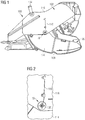
- a luggage bin 100 shown in Figure 1 is design as an aircraft luggage bin which is to be mounted in the overhead region of an aircraft passenger cabin.
- the luggage bin comprises a housing 102 which can be fastened rigidly to a primary structural element (not shown in the figures) of the aircraft by means of a structural holder 104.
- the luggage bin 100 further comprises a shell 106 which is pivotable relative to the housing 102 between a closed transport position and an open loading or unloading position illustrated in Figure 1 .
- an electrical consumer 108 which in the embodiment of a luggage bin 100 shown in the figures is in the form of handle strip lighting.
- a cable 110 In order to supply the electrical consumer 108 with electrical energy, a cable 110 must be guided from outside the luggage bin 100 into an interior of the luggage bin 100, that is to say an interior of the shell 106. To that end, the luggage bin 100 is equipped with a cable guide arrangement 10, which will be described in greater detail below.
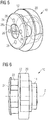
- the cable guide arrangement 10 comprises a shaft bearing element 12 and a shaft element 14 which is rotatably mounted in the shaft bearing element 12.
- the shaft element 14 passes through a first receiving bore 112 which is formed in a side wall 114 of the shell 106 and is connected to the shell 106 in a rotationally secure manner.
- Figure 3 shows an interior of the shell 106
- Figure 14 which illustrates a detailed view of the cable guide arrangement 10, seen from an interior of the shell 106.
- a flange portion 16 of the shaft element 14 serves for fastening the shaft element 14 to the shell 106 of the luggage bin, which flange portion extends radially outwards from an outer circumference of the shaft element 14, which is in hollow cylindrical form, and rests on an inner surface of the side wall 114 of the shell 106 when the cable guide arrangement 10 is mounted in the luggage bin 100.
- the shaft element 14, which forms the pivot axis about which the shell 106 of the luggage bin 100 is pivotable relative to the housing 102, is consequently designed in the form of a hollow shaft through which the cable 110 can be guided from outside the luggage bin 100 into the interior of the shell 106.
- the cable 110 is guided, with respect to the central axis Z of the shaft element 14, along an outer surface of a side wall 116 of the luggage bin housing 102 in the radial direction in the direction of the cable guide arrangement 10 and finally through the opening 18 formed in the shaft element 14 into the interior of the shell 106.
- the cable 110 extends, with respect to the central axis Z of the shaft element 14 of the cable guide arrangement 10, in the radial direction along an inner surface of the side wall 114 of the shell 106 downwards in the direction of a floor 118 of the shell 106, see Figure 3 .
- an electrical separation in the form of a plug to the electronic component. This separation ensures that the shell 106 can also be separated from the housing 102 without dismantling the entire luggage bin 100.
- the shaft bearing element 12 comprises a bearing bush 20 for receiving the shaft element 14 as well as a fastening portion 22 which, when the cable guide arrangement 10 is mounted in the luggage bin 100, passes through a second receiving bore 120 which is formed in the side wall 116 of the luggage bin housing 102.
- the cable guide arrangement 10 further has a cover element 24.
- the cover element 24 is connected to the shaft bearing element 12 by means of four fastening pins 26 in such a manner that a portion of the side wall 116 of the luggage bin housing 102 that adjoins the second receiving bore 120 is received between the bearing bush 20 of the shaft bearing element 12 and the cover element 24 of the cable guide arrangement 10.
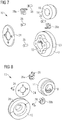
- the cable guide arrangement 10 comprises a first and a second cable guide element 28a, 28b, see Figures 9 to 14 , each of which show detailed representations of the cable guide arrangement 10 from different viewing angles.
- the first cable guide element 28a is connected, with respect to the central axis Z of the shaft element 14, in the region of a first axial end of the cable guide arrangement 10 to the shaft bearing element 12, see in particular Figure 11 .
- the second cable guide element 28b is connected with respect to the central axis Z of the shaft element 14, in the region of a second axial end, opposite the first end, of the cable guide arrangement 10 to the shaft element 14, see in particular Figures 10 , 13 and 14 .
- the cable 110 is guided freely through the opening 18 formed in the shaft element 14.
- the first and second cable guide elements 28a, 28b are arranged at such a distance from one another, in the direction of the central axis Z of the shaft element 18, that the cable 110 is able to twist as a result of a torsional load which acts upon the cable 112 when the shaft element 114 rotates relative to the shaft bearing element 12, without the cable 110 being damaged.
- the portion of the cable 110 which extends between the cable guide elements 28a, 28b can be 20 mm long. However, that distance can vary in dependence on the geometry and the resilience of the cable 110.
- Each cable guide element 28a, 28b comprises a first guide portion 30 and a second guide portion 32.
- the first guide portion 30 serves to deflect the cable 110, which extends in the radial direction with respect to the central axis Z of the shaft element 14, in the direction of the central axis Z of the shaft element 14 with a defined bending radius, see in particular Figures 9, 10 and 14 .
- the first guide portion 30 of each cable guide element 28a, 28b extends, with respect to the central axis Z of the shaft element 18, radially outwards from the second guide portion 32 and is provided with a bearing surface 34 for the cable 110.
- the bearing surface 34 has a curvature which is adapted to a defined bending radius with which the cable 110 is to be deflected in the direction of the central axis Z of the shaft element 14.
- the bearing surface 34 of the first guide portion 30 is curved in the manner of a funnel, the second guide portion 32 projecting beyond the first guide portion 30 in the axial direction, that is to say in the direction of the central axis Z of the shaft element 14, see in particular Figures 9 and 11 .
- each cable guide element 28a, 28b serves to guide the cable 110 parallel to, in particular coaxially with, the central axis Z of the shaft element 14 through the opening 18 extending through the axial element 14.
- the second guide portion 32 has two guide ribs 36, 38 which extend parallel to one another and parallel to the central axis Z of the shaft element 14.
- the guide ribs 36, 38 receive the cable 110 between them and guide the cable 110 parallel to the central axis Z of the shaft element 14 through the opening 18 formed in the shaft element 14, see in particular Figures 11 to 14 .
- the second guide portion 32 is further provided with a receiving portion 40.
- the receiving portion 40 extends between the guide ribs 36, 38 parallel to the central axis Z of the shaft element 14 and has a receiving surface 42 adapted to a cross-section of the cable 110.
- the shape of the receiving surface 42 is adapted to the shape of an outer circumferential surface of a cable 110 having a circular cross-section.
- the receiving surface 42 extends over more than 50% of the outer circumference of the cable 110, as a result of which it is ensured that the cable 110 is held securely in the receiving portion 40, see in particular Figure 13 .
- the cable 110 can thus be dismantled in a simple manner from the cable guide elements 28a, 28b, for example if the cable 110 is to be removed from the cable guide arrangement 10 for maintenance purposes.
- Each cable guide element 28a, 28b comprises a fastening element 44 which extends parallel to the central axis Z of the shaft element 14 from a surface 46 of the first guide portion 30 opposite the bearing surface 34.
- the fastening element 44 formed on the first cable guide element 28a is engaged with a complementary fastening element 48 that is formed on the shaft bearing element 12, see Figure 11 .
- the fastening element 44 of the second cable guide element 28b is engaged with a complementary fastening element 50 that is formed on the shaft element 14, see Figures 10 , 13 and 14 .
- the fastening element 48 formed on the shaft bearing element 12 extends, with respect to the central axis Z of the shaft element 14, inwards in the radial direction from an inner surface of the shaft bearing element 12.
- the fastening element 50 formed on the shaft element 14 extends, with respect to the central axis Z of the shaft element 14, inwards in the radial direction from an inner surface of the shaft element 14.
- Both fastening elements 48, 50 are further provided with an engagement opening 52, 54 which serves to receive the fastening elements 44 of the cable guide elements 28a, 28b.
Landscapes
- Engineering & Computer Science (AREA)
- Aviation & Aerospace Engineering (AREA)
- Flexible Shafts (AREA)
- Details Of Indoor Wiring (AREA)
- Mounting Of Bearings Or Others (AREA)
- Rolling Contact Bearings (AREA)
Claims (15)
- Flugzeuggepäckfach (100) mit einer Kabelführungsanordnung (10), die Folgendes umfasst:- ein Achslagerelement (12),- ein Achselement (14), das drehbar in dem Achslagerelement (12) gelagert ist und von einer sich entlang einer Zentralachse (Z) des Achselements (14) erstreckenden Öffnung (18) durchsetzt ist, und- mindestens ein Kabelführungselement (28a, 28b), das mit dem Achslagerelement (12) oder dem Achselement (14) verbunden ist und einen ersten Führungsabschnitt (30) sowie einen zweiten Führungsabschnitt (32) umfasst, wobei der zweite Führungsabschnitt (32) dazu eingerichtet ist, ein Kabel (110) parallel zu der Zentralachse (Z) des Achselements (14) durch die sich durch das Achselement (14) erstreckende Öffnung (18) zu führen,dadurch gekennzeichnet, dass
der erste Führungsabschnitt (30) dazu eingerichtet ist, das Kabel (110), das sich bezüglich der Zentralachse (Z) des Achselements (14) in radialer Richtung erstreckt, mit einem definierten Biegeradius in Richtung der Zentralachse (Z) des Achselements (14) umzulenken. - Flugzeuggepäckfach (100) nach Anspruch 1,
dadurch gekennzeichnet, dass sich der erste Führungsabschnitt (30) des Kabelführungselements (28a, 28b) bezüglich der Zentralachse (Z) des Achselements (14) von dem zweiten Führungsabschnitt (32) radial nach außen erstreckt und eine Lagerfläche (34) für das Kabel (110) umfasst. - Flugzeuggepäckfach (100) nach Anspruch 2,
dadurch gekennzeichnet, dass die Lagerfläche (34) des ersten Führungsabschnitts (30) zumindest in einem an den zweiten Führungsabschnitt (32) angrenzenden Bereich eine Krümmung aufweist, die an den definierten Biegeradius angepasst ist, mit dem das Kabel (110) in Richtung der Zentralachse (Z) des Achselements (14) umgelenkt werden soll. - Flugzeuggepäckfach (100) nach Anspruch 2 oder 3,
dadurch gekennzeichnet, dass die Lagerfläche (34) des ersten Führungsabschnitts (30) zumindest in einem an den zweiten Führungsabschnitt (32) angrenzenden Bereich trichterartig gekrümmt ist. - Flugzeuggepäckfach (100) nach einem der Ansprüche 1 bis 4,
dadurch gekennzeichnet, dass der zweite Führungsabschnitt (32) des Kabelführungselements (28a, 28b) zwei sich parallel zueinander und parallel zu der Zentralachse (Z) des Achselements (14) erstreckende Führungsrippen (36, 38) umfasst, die dazu eingerichtet sind, das Kabel (110) zwischen sich aufzunehmen und parallel zu der Zentralachse (Z) des Achselements (14) durch die sich durch das Achselement (14) erstreckende Öffnung (18) zu führen. - Flugzeuggepäckfach (100) nach Anspruch 5,
dadurch gekennzeichnet, dass der zweite Führungsabschnitt (32) einen sich zwischen den Führungsrippen (36, 38) parallel zu der Zentralachse (Z) des Achselements (14) erstreckenden Aufnahmeabschnitt (40) umfasst, der eine an einen Querschnitt des Kabels (110) angepasste Aufnahmefläche (42) zur Aufnahme des Kabels (110) ausweist. - Flugzeuggepäckfach (100) nach Anspruch 6,
dadurch gekennzeichnet, dass einander zugewandte Seitenflächen der Führungsrippen (36, 38) einen ausgehend von dem Aufnahmeabschnitt (40) bezüglich der Zentralachse (Z) des Achselements (14) in radialer Richtung zunehmenden Abstand voneinander aufweisen. - Flugzeuggepäckfach (100) nach einem Ansprüche 1 bis 7,
dadurch gekennzeichnet, dass das Kabelführungselement (28a, 28b) ein Befestigungselement (44) umfasst, das mit einem komplementären Befestigungselement (48, 50), welches an dem Achslagerelement (12) oder dem Achselement (14) ausgebildet ist, verrastet ist. - Flugzeuggepäckfach (100) nach Anspruch 8,
dadurch gekennzeichnet, dass sich das Befestigungselement (44) des Kabelführungselements (28a, 28b) parallel zu der Zentralachse (Z) des Achselements (14) von einer der Lagerfläche (34) gegenüberliegenden Fläche (46) des ersten Führungsabschnitts (30) erstreckt. - Flugzeuggepäckfach (100) nach Anspruch 8 oder 9,
dadurch gekennzeichnet, dass sich das an dem Achslagerelement (12) oder dem Achselement (14) ausgebildete komplementäre Befestigungselement (48, 50) bezüglich der Zentralachse (Z) des Achselements (14) in radialer Richtung von einer Innenfläche des Achslagerelements (12) oder des Achselements (14) erstreckt und eine Rastöffnung (52, 54) zur Aufnahme des Befestigungselements (44) des Kabelführungselements (28a, 28b) aufweist. - Flugzeuggepäckfach (100) einem der Ansprüche 1 bis 10,
dadurch gekennzeichnet, dass die Kabelführungsanordnung (10) ein erstes Kabelführungselement (28a), das bezüglich der Zentralachse (Z) des Achselements (14) im Bereich eines ersten Endes der Kabelführungsanordnung (10) mit dem Achslagerelement (12) verbunden ist, und ein zweites Kabelführungselement (28b) umfasst, das bezüglich der Zentralachse (Z) des Achselements (14) im Bereich eines dem ersten Ende gegenüberliegenden zweiten Endes der Kabelführungsanordnung (10) mit dem Achselement (14) verbunden ist, wobei das erste und das zweite Kabelführungselement (28a, 28b) in Richtung der Zentralachse (Z) des Achselements (14) in einem derartigen Abstand voneinander angeordnet sind, dass sich das Kabel (110), das durch die sich durch das Achselement (14) erstreckende Öffnung (18) geführt ist, infolge einer bei einer Drehung des Achselements (14) relativ zu dem Achslagerelement (12) auf das Kabel (110) wirkenden Torsionsbelastung verdrillen kann, ohne dass das Kabel (110) beschädigt wird. - Flugzeuggepäckfach (100) nach einem der Ansprüche 1 bis 11, gekennzeichnet durch ein mit dem Achslagerelement (12) verbundenes Abdeckelement (24).
- Flugzeuggepäckfach (100) nach einem der Ansprüche 1 bis 12, gekennzeichnet durch:- ein Gehäuse (102), und- eine relativ zu dem Gehäuse (102) zwischen einer geschlossenen Transportstellung und einer geöffneten Be- bzw. Entladestellung verschwenkbaren Schale (106),wobei eine Schwenkachse, um die die Schale (106) relativ zu dem Gehäuse (102) verschwenkbar ist, durch das Achselement (14) der Kabelführungsanordnung (10) gebildet wird.
- Flugzeuggepäckfach (100) nach Anspruch 13,
dadurch gekennzeichnet, dass das Achselement (14) der Kabelführungsanordnung (10) eine erste Aufnahmebohrung (112) durchsetzt, die in einer Seitenwand (114) der Schale (106) ausgebildet ist, und drehfest mit der Schale (106) verbunden ist. - Flugzeuggepäckfach (100) nach Anspruch 13 oder 14, sofern von Anspruch 12 abhängig,
dadurch gekennzeichnet, dass das Achslagerelement (12) der Kabelführungsanordnung (10) eine zweite Aufnahmebohrung (120) durchsetzt, die in einer Seitenwand (116) des Gehäuses (102) ausgebildet ist, und drehfest mit dem Gehäuse (102) verbunden ist, wobei ein zu der zweiten Aufnahmebohrung (120) benachbarter Abschnitt der Seitenwand (116) des Gehäuses (102) zwischen einer Lagerbuchse (20) des Achslagerelements (12) und dem Abdeckelement (24) der Kabelführungsanordnung (10) aufgenommen ist.
Applications Claiming Priority (2)
| Application Number | Priority Date | Filing Date | Title |
|---|---|---|---|
| DE102014012125.9A DE102014012125A1 (de) | 2014-08-14 | 2014-08-14 | Kabelführungsanordnung für ein Gepäckfach |
| PCT/EP2015/068380 WO2016023866A1 (en) | 2014-08-14 | 2015-08-10 | Cable guide arrangement for a luggage bin |
Publications (2)
| Publication Number | Publication Date |
|---|---|
| EP3180246A1 EP3180246A1 (de) | 2017-06-21 |
| EP3180246B1 true EP3180246B1 (de) | 2020-07-15 |
Family
ID=53800990
Family Applications (1)
| Application Number | Title | Priority Date | Filing Date |
|---|---|---|---|
| EP15748246.4A Active EP3180246B1 (de) | 2014-08-14 | 2015-08-10 | Gepäckfach |
Country Status (4)
| Country | Link |
|---|---|
| US (1) | US10407172B2 (de) |
| EP (1) | EP3180246B1 (de) |
| DE (1) | DE102014012125A1 (de) |
| WO (1) | WO2016023866A1 (de) |
Families Citing this family (8)
| Publication number | Priority date | Publication date | Assignee | Title |
|---|---|---|---|---|
| AT515849A1 (de) * | 2014-05-26 | 2015-12-15 | Facc Ag | Überkopf-Gepäckfach |
| DE102016206383A1 (de) * | 2016-04-15 | 2017-10-19 | Airbus Operations Gmbh | Luftfahrzeug-Deckenverkleidungselement mit einer Trägerplattform |
| AT518187B1 (de) * | 2016-06-21 | 2017-08-15 | Simplon Fahrrad Gmbh | Kabelführungskörper |
| WO2018035154A1 (en) * | 2016-08-16 | 2018-02-22 | C&D Zodiac, Inc. | Aircraft storage bin bucket with space efficient corner joint |
| ES2927269T3 (es) * | 2016-10-21 | 2022-11-03 | Facc Ag | Compartimiento de equipaje superior para un avión |
| US10906458B2 (en) * | 2017-03-10 | 2021-02-02 | The Boeing Company | Vehicles including electronic stowage bin control systems |
| DE102017003051A1 (de) * | 2017-03-29 | 2018-10-04 | Diehl Aviation Laupheim Gmbh | Überkopfstaufach für ein Passagierflugzeug |
| AT526728B1 (de) | 2022-11-25 | 2025-06-15 | Facc Ag | Kabinenausstattungseinheit und Verfahren zum Zusammensetzen der Kabinenausstattungseinheit |
Family Cites Families (16)
| Publication number | Priority date | Publication date | Assignee | Title |
|---|---|---|---|---|
| DE59708788D1 (de) * | 1996-03-15 | 2003-01-09 | Airbus Gmbh | Beleuchtungssystem in Passagierkabinen, insbesondere für Passagierflugzeuge |
| DE29906645U1 (de) * | 1999-04-15 | 2000-08-24 | DOYMA GmbH & Co, 28876 Oyten | Durchführungs-Vorrichtung zum abgedichteten Durchführen mindestens einer Leistung durch einen in der Wand o.dgl. ausgebildeten Durchbruch |
| FR2808753B1 (fr) | 2000-05-12 | 2002-08-16 | Peugeot Citroen Automobiles Sa | Vehicule automobile comportant un module de rangement escamotable |
| DE102005033259B4 (de) | 2005-07-15 | 2012-03-08 | Airbus Operations Gmbh | Notöffnungsvorrichtung für ein Gepäckfach mit einer absenkbaren Schale |
| US7723935B2 (en) * | 2006-08-25 | 2010-05-25 | The Boeing Company | System and method for compartment control |
| US7893645B2 (en) * | 2006-08-25 | 2011-02-22 | The Boeing Company | System and method for compartment control |
| US20080078871A1 (en) * | 2006-08-25 | 2008-04-03 | The Boeing Company | System and method for electronically latching compartments |
| US7762737B2 (en) * | 2006-11-09 | 2010-07-27 | The Boeing Company | System and method for stowage compartment pivot assembly |
| DE102008034779A1 (de) * | 2008-07-25 | 2010-01-28 | Airbus Deutschland Gmbh | Vorrichtung zur drehbaren Lagerung eines Flugzeuginnenausstattungsbauteils |
| DE102009057900B4 (de) * | 2009-12-11 | 2011-11-10 | Gabo Systemtechnik Gmbh | Wanddurchführung zur Durchführung von Kabeln, Kabelschutzrohren oder sonstigen Leitungen |
| US20110140462A1 (en) * | 2009-12-11 | 2011-06-16 | Dennis Carl Lin | Lockable Cable-Actuated Latching Mechanism |
| US8770515B1 (en) * | 2010-06-02 | 2014-07-08 | The Boeing Company | Movement assistance system for a storage bin |
| DE102010034027B4 (de) * | 2010-08-11 | 2022-03-03 | Diehl Aviation Laupheim Gmbh | Überkopfgepäckfach |
| US8899390B2 (en) * | 2012-02-14 | 2014-12-02 | C&D Zodiac, Inc. | Freewheeling rotary damping mechanism |
| US9371674B2 (en) * | 2012-03-26 | 2016-06-21 | Itt Manufacturing Enterprises Llc | Rotary hydraulic damper for pivoting stowage bin |
| US9578962B2 (en) * | 2013-08-20 | 2017-02-28 | The Boeing Company | Translating stowage bin and method of assembly |
-
2014
- 2014-08-14 DE DE102014012125.9A patent/DE102014012125A1/de not_active Withdrawn
-
2015
- 2015-08-10 EP EP15748246.4A patent/EP3180246B1/de active Active
- 2015-08-10 WO PCT/EP2015/068380 patent/WO2016023866A1/en not_active Ceased
-
2017
- 2017-02-09 US US15/428,908 patent/US10407172B2/en active Active
Non-Patent Citations (1)
| Title |
|---|
| None * |
Also Published As
| Publication number | Publication date |
|---|---|
| EP3180246A1 (de) | 2017-06-21 |
| US10407172B2 (en) | 2019-09-10 |
| WO2016023866A1 (en) | 2016-02-18 |
| US20170152045A1 (en) | 2017-06-01 |
| DE102014012125A1 (de) | 2016-02-18 |
Similar Documents
| Publication | Publication Date | Title |
|---|---|---|
| US10407172B2 (en) | Cable guide arrangement for a luggage bin | |
| US7128295B2 (en) | Pivot mechanism for quick installation of stowage bins or rotating items | |
| EP3925571B1 (de) | Bürstenkopf für elektrische zahnbürste | |
| US8733699B2 (en) | Overhead luggage compartment | |
| US10086781B2 (en) | Push through grommet | |
| US8596153B2 (en) | Drive device | |
| US8833698B2 (en) | Overhead luggage compartment for vehicle cabin | |
| CN105570290B (zh) | 支撑火车轮轴的传感器轴箱轴承单元及相关的传感器盖 | |
| US20170274831A1 (en) | Vehicle | |
| EP3538809B1 (de) | Konzentrischer videoarmschwenkmechanismus | |
| US9776538B1 (en) | Armrest hinge with cable pass-through | |
| AU2017202775A1 (en) | Wiring structure of grip heater | |
| US8439589B2 (en) | Device for rotatably bearing an aircraft interior fitting component | |
| JP2016107816A (ja) | 車両用視認装置 | |
| US10137924B2 (en) | Adjustable steering column having improved rigidity | |
| EP2162623B1 (de) | Kupplungsteil zur befestigung und entnahme eines abnehmbaren zubehörteils in zusammenhang mit einer stationären trägerstruktur | |
| EP3059486B1 (de) | Unterstützungsstruktur, player und mobile vorrichtung damit | |
| US20160257233A1 (en) | Bus Hand Pole | |
| US20160137039A1 (en) | Insulator for elongate member | |
| KR200478023Y1 (ko) | 차량용 암레스트 조립장치 | |
| EP3819146B1 (de) | Eine unterstützungsstruktur für eine plane für fahrzeuge, anhänger und behälter | |
| KR102282225B1 (ko) | 차량용 수납장치 | |
| US9506431B2 (en) | Detachable connecting device for connecting at least two functional components and functional components | |
| PL4117958T3 (pl) | Konstrukcja pojazdu z ułatwionym dostępem dla pasażera | |
| JP7151584B2 (ja) | グロメット |
Legal Events
| Date | Code | Title | Description |
|---|---|---|---|
| STAA | Information on the status of an ep patent application or granted ep patent |
Free format text: STATUS: THE INTERNATIONAL PUBLICATION HAS BEEN MADE |
|
| PUAI | Public reference made under article 153(3) epc to a published international application that has entered the european phase |
Free format text: ORIGINAL CODE: 0009012 |
|
| STAA | Information on the status of an ep patent application or granted ep patent |
Free format text: STATUS: REQUEST FOR EXAMINATION WAS MADE |
|
| 17P | Request for examination filed |
Effective date: 20170126 |
|
| AK | Designated contracting states |
Kind code of ref document: A1 Designated state(s): AL AT BE BG CH CY CZ DE DK EE ES FI FR GB GR HR HU IE IS IT LI LT LU LV MC MK MT NL NO PL PT RO RS SE SI SK SM TR |
|
| AX | Request for extension of the european patent |
Extension state: BA ME |
|
| DAV | Request for validation of the european patent (deleted) | ||
| DAX | Request for extension of the european patent (deleted) | ||
| STAA | Information on the status of an ep patent application or granted ep patent |
Free format text: STATUS: EXAMINATION IS IN PROGRESS |
|
| 17Q | First examination report despatched |
Effective date: 20191209 |
|
| GRAP | Despatch of communication of intention to grant a patent |
Free format text: ORIGINAL CODE: EPIDOSNIGR1 |
|
| STAA | Information on the status of an ep patent application or granted ep patent |
Free format text: STATUS: GRANT OF PATENT IS INTENDED |
|
| INTG | Intention to grant announced |
Effective date: 20200228 |
|
| GRAS | Grant fee paid |
Free format text: ORIGINAL CODE: EPIDOSNIGR3 |
|
| GRAA | (expected) grant |
Free format text: ORIGINAL CODE: 0009210 |
|
| STAA | Information on the status of an ep patent application or granted ep patent |
Free format text: STATUS: THE PATENT HAS BEEN GRANTED |
|
| AK | Designated contracting states |
Kind code of ref document: B1 Designated state(s): AL AT BE BG CH CY CZ DE DK EE ES FI FR GB GR HR HU IE IS IT LI LT LU LV MC MK MT NL NO PL PT RO RS SE SI SK SM TR |
|
| REG | Reference to a national code |
Ref country code: CH Ref legal event code: EP Ref country code: GB Ref legal event code: FG4D |
|
| REG | Reference to a national code |
Ref country code: IE Ref legal event code: FG4D |
|
| REG | Reference to a national code |
Ref country code: DE Ref legal event code: R096 Ref document number: 602015055772 Country of ref document: DE |
|
| REG | Reference to a national code |
Ref country code: AT Ref legal event code: REF Ref document number: 1290780 Country of ref document: AT Kind code of ref document: T Effective date: 20200815 |
|
| REG | Reference to a national code |
Ref country code: LT Ref legal event code: MG4D |
|
| REG | Reference to a national code |
Ref country code: AT Ref legal event code: MK05 Ref document number: 1290780 Country of ref document: AT Kind code of ref document: T Effective date: 20200715 |
|
| REG | Reference to a national code |
Ref country code: NL Ref legal event code: MP Effective date: 20200715 |
|
| PG25 | Lapsed in a contracting state [announced via postgrant information from national office to epo] |
Ref country code: NO Free format text: LAPSE BECAUSE OF FAILURE TO SUBMIT A TRANSLATION OF THE DESCRIPTION OR TO PAY THE FEE WITHIN THE PRESCRIBED TIME-LIMIT Effective date: 20201015 Ref country code: GR Free format text: LAPSE BECAUSE OF FAILURE TO SUBMIT A TRANSLATION OF THE DESCRIPTION OR TO PAY THE FEE WITHIN THE PRESCRIBED TIME-LIMIT Effective date: 20201016 Ref country code: ES Free format text: LAPSE BECAUSE OF FAILURE TO SUBMIT A TRANSLATION OF THE DESCRIPTION OR TO PAY THE FEE WITHIN THE PRESCRIBED TIME-LIMIT Effective date: 20200715 Ref country code: HR Free format text: LAPSE BECAUSE OF FAILURE TO SUBMIT A TRANSLATION OF THE DESCRIPTION OR TO PAY THE FEE WITHIN THE PRESCRIBED TIME-LIMIT Effective date: 20200715 Ref country code: SE Free format text: LAPSE BECAUSE OF FAILURE TO SUBMIT A TRANSLATION OF THE DESCRIPTION OR TO PAY THE FEE WITHIN THE PRESCRIBED TIME-LIMIT Effective date: 20200715 Ref country code: FI Free format text: LAPSE BECAUSE OF FAILURE TO SUBMIT A TRANSLATION OF THE DESCRIPTION OR TO PAY THE FEE WITHIN THE PRESCRIBED TIME-LIMIT Effective date: 20200715 Ref country code: LT Free format text: LAPSE BECAUSE OF FAILURE TO SUBMIT A TRANSLATION OF THE DESCRIPTION OR TO PAY THE FEE WITHIN THE PRESCRIBED TIME-LIMIT Effective date: 20200715 Ref country code: AT Free format text: LAPSE BECAUSE OF FAILURE TO SUBMIT A TRANSLATION OF THE DESCRIPTION OR TO PAY THE FEE WITHIN THE PRESCRIBED TIME-LIMIT Effective date: 20200715 Ref country code: BG Free format text: LAPSE BECAUSE OF FAILURE TO SUBMIT A TRANSLATION OF THE DESCRIPTION OR TO PAY THE FEE WITHIN THE PRESCRIBED TIME-LIMIT Effective date: 20201015 Ref country code: PT Free format text: LAPSE BECAUSE OF FAILURE TO SUBMIT A TRANSLATION OF THE DESCRIPTION OR TO PAY THE FEE WITHIN THE PRESCRIBED TIME-LIMIT Effective date: 20201116 |
|
| PG25 | Lapsed in a contracting state [announced via postgrant information from national office to epo] |
Ref country code: PL Free format text: LAPSE BECAUSE OF FAILURE TO SUBMIT A TRANSLATION OF THE DESCRIPTION OR TO PAY THE FEE WITHIN THE PRESCRIBED TIME-LIMIT Effective date: 20200715 Ref country code: RS Free format text: LAPSE BECAUSE OF FAILURE TO SUBMIT A TRANSLATION OF THE DESCRIPTION OR TO PAY THE FEE WITHIN THE PRESCRIBED TIME-LIMIT Effective date: 20200715 Ref country code: LV Free format text: LAPSE BECAUSE OF FAILURE TO SUBMIT A TRANSLATION OF THE DESCRIPTION OR TO PAY THE FEE WITHIN THE PRESCRIBED TIME-LIMIT Effective date: 20200715 Ref country code: IS Free format text: LAPSE BECAUSE OF FAILURE TO SUBMIT A TRANSLATION OF THE DESCRIPTION OR TO PAY THE FEE WITHIN THE PRESCRIBED TIME-LIMIT Effective date: 20201115 |
|
| PG25 | Lapsed in a contracting state [announced via postgrant information from national office to epo] |
Ref country code: NL Free format text: LAPSE BECAUSE OF FAILURE TO SUBMIT A TRANSLATION OF THE DESCRIPTION OR TO PAY THE FEE WITHIN THE PRESCRIBED TIME-LIMIT Effective date: 20200715 |
|
| REG | Reference to a national code |
Ref country code: CH Ref legal event code: PL |
|
| REG | Reference to a national code |
Ref country code: DE Ref legal event code: R097 Ref document number: 602015055772 Country of ref document: DE |
|
| PG25 | Lapsed in a contracting state [announced via postgrant information from national office to epo] |
Ref country code: DK Free format text: LAPSE BECAUSE OF FAILURE TO SUBMIT A TRANSLATION OF THE DESCRIPTION OR TO PAY THE FEE WITHIN THE PRESCRIBED TIME-LIMIT Effective date: 20200715 Ref country code: CZ Free format text: LAPSE BECAUSE OF FAILURE TO SUBMIT A TRANSLATION OF THE DESCRIPTION OR TO PAY THE FEE WITHIN THE PRESCRIBED TIME-LIMIT Effective date: 20200715 Ref country code: CH Free format text: LAPSE BECAUSE OF NON-PAYMENT OF DUE FEES Effective date: 20200831 Ref country code: IT Free format text: LAPSE BECAUSE OF FAILURE TO SUBMIT A TRANSLATION OF THE DESCRIPTION OR TO PAY THE FEE WITHIN THE PRESCRIBED TIME-LIMIT Effective date: 20200715 Ref country code: LU Free format text: LAPSE BECAUSE OF NON-PAYMENT OF DUE FEES Effective date: 20200810 Ref country code: MC Free format text: LAPSE BECAUSE OF FAILURE TO SUBMIT A TRANSLATION OF THE DESCRIPTION OR TO PAY THE FEE WITHIN THE PRESCRIBED TIME-LIMIT Effective date: 20200715 Ref country code: LI Free format text: LAPSE BECAUSE OF NON-PAYMENT OF DUE FEES Effective date: 20200831 Ref country code: EE Free format text: LAPSE BECAUSE OF FAILURE TO SUBMIT A TRANSLATION OF THE DESCRIPTION OR TO PAY THE FEE WITHIN THE PRESCRIBED TIME-LIMIT Effective date: 20200715 Ref country code: SM Free format text: LAPSE BECAUSE OF FAILURE TO SUBMIT A TRANSLATION OF THE DESCRIPTION OR TO PAY THE FEE WITHIN THE PRESCRIBED TIME-LIMIT Effective date: 20200715 Ref country code: RO Free format text: LAPSE BECAUSE OF FAILURE TO SUBMIT A TRANSLATION OF THE DESCRIPTION OR TO PAY THE FEE WITHIN THE PRESCRIBED TIME-LIMIT Effective date: 20200715 |
|
| PLBE | No opposition filed within time limit |
Free format text: ORIGINAL CODE: 0009261 |
|
| STAA | Information on the status of an ep patent application or granted ep patent |
Free format text: STATUS: NO OPPOSITION FILED WITHIN TIME LIMIT |
|
| REG | Reference to a national code |
Ref country code: BE Ref legal event code: MM Effective date: 20200831 |
|
| PG25 | Lapsed in a contracting state [announced via postgrant information from national office to epo] |
Ref country code: AL Free format text: LAPSE BECAUSE OF FAILURE TO SUBMIT A TRANSLATION OF THE DESCRIPTION OR TO PAY THE FEE WITHIN THE PRESCRIBED TIME-LIMIT Effective date: 20200715 |
|
| 26N | No opposition filed |
Effective date: 20210416 |
|
| PG25 | Lapsed in a contracting state [announced via postgrant information from national office to epo] |
Ref country code: SK Free format text: LAPSE BECAUSE OF FAILURE TO SUBMIT A TRANSLATION OF THE DESCRIPTION OR TO PAY THE FEE WITHIN THE PRESCRIBED TIME-LIMIT Effective date: 20200715 |
|
| PG25 | Lapsed in a contracting state [announced via postgrant information from national office to epo] |
Ref country code: SI Free format text: LAPSE BECAUSE OF FAILURE TO SUBMIT A TRANSLATION OF THE DESCRIPTION OR TO PAY THE FEE WITHIN THE PRESCRIBED TIME-LIMIT Effective date: 20200715 Ref country code: IE Free format text: LAPSE BECAUSE OF NON-PAYMENT OF DUE FEES Effective date: 20200810 Ref country code: BE Free format text: LAPSE BECAUSE OF NON-PAYMENT OF DUE FEES Effective date: 20200831 |
|
| PG25 | Lapsed in a contracting state [announced via postgrant information from national office to epo] |
Ref country code: TR Free format text: LAPSE BECAUSE OF FAILURE TO SUBMIT A TRANSLATION OF THE DESCRIPTION OR TO PAY THE FEE WITHIN THE PRESCRIBED TIME-LIMIT Effective date: 20200715 Ref country code: MT Free format text: LAPSE BECAUSE OF FAILURE TO SUBMIT A TRANSLATION OF THE DESCRIPTION OR TO PAY THE FEE WITHIN THE PRESCRIBED TIME-LIMIT Effective date: 20200715 Ref country code: CY Free format text: LAPSE BECAUSE OF FAILURE TO SUBMIT A TRANSLATION OF THE DESCRIPTION OR TO PAY THE FEE WITHIN THE PRESCRIBED TIME-LIMIT Effective date: 20200715 |
|
| PG25 | Lapsed in a contracting state [announced via postgrant information from national office to epo] |
Ref country code: MK Free format text: LAPSE BECAUSE OF FAILURE TO SUBMIT A TRANSLATION OF THE DESCRIPTION OR TO PAY THE FEE WITHIN THE PRESCRIBED TIME-LIMIT Effective date: 20200715 |
|
| PGFP | Annual fee paid to national office [announced via postgrant information from national office to epo] |
Ref country code: GB Payment date: 20230822 Year of fee payment: 9 |
|
| GBPC | Gb: european patent ceased through non-payment of renewal fee |
Effective date: 20240810 |
|
| PG25 | Lapsed in a contracting state [announced via postgrant information from national office to epo] |
Ref country code: GB Free format text: LAPSE BECAUSE OF NON-PAYMENT OF DUE FEES Effective date: 20240810 |
|
| PGFP | Annual fee paid to national office [announced via postgrant information from national office to epo] |
Ref country code: DE Payment date: 20250820 Year of fee payment: 11 |
|
| PGFP | Annual fee paid to national office [announced via postgrant information from national office to epo] |
Ref country code: FR Payment date: 20250829 Year of fee payment: 11 |