EP3053717A1 - Arbeitsgerät - Google Patents
Arbeitsgerät Download PDFInfo
- Publication number
- EP3053717A1 EP3053717A1 EP15000308.5A EP15000308A EP3053717A1 EP 3053717 A1 EP3053717 A1 EP 3053717A1 EP 15000308 A EP15000308 A EP 15000308A EP 3053717 A1 EP3053717 A1 EP 3053717A1
- Authority
- EP
- European Patent Office
- Prior art keywords
- housing cover
- housing
- opening
- fastener
- dome
- Prior art date
- Legal status (The legal status is an assumption and is not a legal conclusion. Google has not performed a legal analysis and makes no representation as to the accuracy of the status listed.)
- Granted
Links
Images



Classifications
-
- B—PERFORMING OPERATIONS; TRANSPORTING
- B27—WORKING OR PRESERVING WOOD OR SIMILAR MATERIAL; NAILING OR STAPLING MACHINES IN GENERAL
- B27B—SAWS FOR WOOD OR SIMILAR MATERIAL; COMPONENTS OR ACCESSORIES THEREFOR
- B27B17/00—Chain saws; Equipment therefor
- B27B17/02—Chain saws equipped with guide bar
-
- B—PERFORMING OPERATIONS; TRANSPORTING
- B25—HAND TOOLS; PORTABLE POWER-DRIVEN TOOLS; MANIPULATORS
- B25F—COMBINATION OR MULTI-PURPOSE TOOLS NOT OTHERWISE PROVIDED FOR; DETAILS OR COMPONENTS OF PORTABLE POWER-DRIVEN TOOLS NOT PARTICULARLY RELATED TO THE OPERATIONS PERFORMED AND NOT OTHERWISE PROVIDED FOR
- B25F5/00—Details or components of portable power-driven tools not particularly related to the operations performed and not otherwise provided for
-
- B—PERFORMING OPERATIONS; TRANSPORTING
- B23—MACHINE TOOLS; METAL-WORKING NOT OTHERWISE PROVIDED FOR
- B23D—PLANING; SLOTTING; SHEARING; BROACHING; SAWING; FILING; SCRAPING; LIKE OPERATIONS FOR WORKING METAL BY REMOVING MATERIAL, NOT OTHERWISE PROVIDED FOR
- B23D57/00—Sawing machines or sawing devices not covered by one of the preceding groups B23D45/00 - B23D55/00
- B23D57/02—Sawing machines or sawing devices not covered by one of the preceding groups B23D45/00 - B23D55/00 with chain saws
-
- B—PERFORMING OPERATIONS; TRANSPORTING
- B23—MACHINE TOOLS; METAL-WORKING NOT OTHERWISE PROVIDED FOR
- B23D—PLANING; SLOTTING; SHEARING; BROACHING; SAWING; FILING; SCRAPING; LIKE OPERATIONS FOR WORKING METAL BY REMOVING MATERIAL, NOT OTHERWISE PROVIDED FOR
- B23D57/00—Sawing machines or sawing devices not covered by one of the preceding groups B23D45/00 - B23D55/00
- B23D57/02—Sawing machines or sawing devices not covered by one of the preceding groups B23D45/00 - B23D55/00 with chain saws
- B23D57/023—Sawing machines or sawing devices not covered by one of the preceding groups B23D45/00 - B23D55/00 with chain saws hand-held or hand-operated
-
- B—PERFORMING OPERATIONS; TRANSPORTING
- B25—HAND TOOLS; PORTABLE POWER-DRIVEN TOOLS; MANIPULATORS
- B25F—COMBINATION OR MULTI-PURPOSE TOOLS NOT OTHERWISE PROVIDED FOR; DETAILS OR COMPONENTS OF PORTABLE POWER-DRIVEN TOOLS NOT PARTICULARLY RELATED TO THE OPERATIONS PERFORMED AND NOT OTHERWISE PROVIDED FOR
- B25F5/00—Details or components of portable power-driven tools not particularly related to the operations performed and not otherwise provided for
- B25F5/02—Construction of casings, bodies or handles
-
- B—PERFORMING OPERATIONS; TRANSPORTING
- B27—WORKING OR PRESERVING WOOD OR SIMILAR MATERIAL; NAILING OR STAPLING MACHINES IN GENERAL
- B27B—SAWS FOR WOOD OR SIMILAR MATERIAL; COMPONENTS OR ACCESSORIES THEREFOR
- B27B17/00—Chain saws; Equipment therefor
Definitions
- the invention relates to a hand-held implement of the type specified in the preamble of claim 1.
- a hand-held implement namely a hand-held chainsaw known whose sprocket cover is fixed on captive held nuts on the housing.
- the surface of the sprocket cover is flat in the area of the nuts, and the nuts are designed as collar nuts. This results in a large contact surface of the nut on the sprocket cover.
- the outer side of the collar nut is spaced comparatively far from the bearing surface of the nut on the sprocket cover due to the height of the key surfaces and the collar, and there is a large width of the mother.
- the invention has for its object to provide a hand-held implement of the generic type, in which a secure tightening and loosening of the fasteners is possible even with small extension of the key surfaces of the fastener.
- the housing cover has a dome projecting outwardly on the housing cover outside, which forms a bearing surface for the fastening element and through which the opening extends.
- the maximum radial distance of the outer circumference of the dome to the longitudinal center axis of a stud bolt of the working device is on the support surface and in a first region adjacent to the support surface at most as large as half the width of the wrench flats of the fastener.
- the extension of the implement in the direction of the longitudinal center axis of the stud, in a chain saw in particular the width of the chainsaw can be reduced. If the implement is a chain saw, then the lateral distance between the saw chain and the housing cover outside or the outside of the fasteners can be reduced, so that can be cut closer to an obstacle with the chainsaw.
- the term "radial" designates the radial direction to the longitudinal center axis of the stud.
- the arranged on the housing cover outside portion of the fastener is advantageously limited in a plan view in the direction of the longitudinal central axis of the stud bolt by a peripheral contour having the key surfaces, and the dome is at least on the support surface and in the adjacent to the support surface first region in a plan view in Direction of the longitudinal central axis of the stud within the enclosed by the peripheral contour surface.
- This allows a tool that engages the key surfaces to be slid over the first area of the mandrel.
- slippage of the tool is avoided by the key surfaces even at low height of the key surfaces.
- the height of the key surfaces is measured parallel to the longitudinal central axis of the stud.
- the key surfaces are formed on an external hexagon of the fastener.
- the arranged on the housing cover outside portion of the fastener is bounded in a plan view in the direction of the longitudinal center axis of the stud by the hexagon, and the dome is at least on the support surface and in the abutting surface adjacent the first region in the plan view in the direction of the longitudinal center axis of the stud inside of the hexagon.
- the height of the area of the dome adjoining the support surface is at least 2 mm.
- the height of the area of the dome adjoining the support surface is advantageously at least 3 mm, preferably at least 4 mm.
- the tool 2 mm, in particular 3 mm, preferably at least 4 mm are pushed over the cathedral. Slipping of the tool from the key surfaces is thereby avoided.
- the key surfaces can thereby be made comparatively low.
- the height of the key surfaces measured parallel to the longitudinal central axis of the stud bolt is advantageously less than 10 mm, in particular less than 8 mm.
- the height of the key surfaces measured parallel to the longitudinal central axis of the stud bolt is 4 mm to 6 mm.
- the housing cover is in particular made of metal, and the contact surface formed on the dome is machined.
- the housing cover advantageously has an outer layer on the metal.
- the outer layer may be, for example, a paint or a coating or the like.
- the outer layer does not extend to the support surface.
- the support surface is machined after the application of the outer layer, so that there is a defined, flat bearing surface.
- the key surfaces advantageously adjoin an end face of the fastening element, which bears against the bearing surface. The key surfaces thus extend to the support surface, so that the largest possible axial extent of the key surfaces results.
- the fastener is held captive in the opening of the housing cover. Even with completely unscrewed from the stud fastener, the fastener can not thereby remove from the housing cover, but is held on the housing cover.
- the fastener has a in the opening projecting retaining edge, which engages behind an edge of the opening. The retaining edge holds the fastener even on the housing cover, when the fastener is completely unscrewed from the stud.
- the edge of the opening is advantageously formed in the dome.
- a comparatively large width of the housing cover in this area is required to allow the axial relative movement of the fastening element relative to the housing cover when attaching and detaching the fastener. At the same time a sufficiently large stroke length for a tool for rotating the fastener is needed.
- the overall width of the housing cover can be reduced because the measured height of the first portion in the axial direction as well as axial length for the securing element of the fastener as well is used as a push-on length for a tool.
- the axial length is the length measured in the direction of the longitudinal central axis of the stud bolt.
- the edge of the opening is arranged in a second region of the dome whose outer diameter is greater than the wrench size of the key surfaces. This allows a sufficiently large outer diameter for the edge can be achieved.
- the edge of the opening is arranged in the first region of the dome adjoining the support surface.
- the retaining edge is advantageously formed on a projecting into the opening sleeve-shaped portion of the fastener.
- the distance between the retaining edge and the edge are clamped held tool unit, the thread length of the fastener and the thread length of the stud advantageously coordinated so that the fastener completely held at between housing and housing cover held tool unit of Thread of the stud bolt can be unscrewed.
- the cover must therefore not change its position.
- a fastening element By means of two fastening elements, a fastening element can thereby be completely released before the second fastening element is released. This results in easy handling.
- the housing cover is a sprocket cover
- the tool unit includes a clamped between the sprocket cover and the housing guide rail.
- the tool unit may also comprise another tool, in particular a grinding wheel.
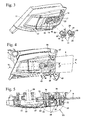
- Fig. 1 shows as an exemplary embodiment of a working device, a hand-held power saw 1.
- the power saw 1 has a housing 2 to which a rear handle 3 and a handle 4 for guiding the power saw 1 are fixed during operation.
- an operating lever 6 and an operating lever lock 7 are pivotally mounted.
- a tool unit 39 is fixed, which comprises a guide rail 8 and a saw chain 9 arranged circumferentially on the guide rail 8.
- a differently constructed tool unit 39 can also be provided.
- a hand guard 5 is arranged, which is pivotally mounted on the housing 2 in the exemplary embodiment and serves to trigger a chain brake device, not shown.
- a drive motor 12 is arranged, which is advantageously designed as an internal combustion engine.
- the drive motor 12 may also be a cable or a battery powered electric motor.
- the housing 2 is the motor housing of the power saw 1.
- the drive motor 12 drives a sprocket 15 rotating, which in turn drives the saw chain 9.
- the sprocket 15 is covered by a housing cover 11.
- the housing cover 11 is a sprocket cover.
- the housing cover 11 has a housing cover 2 outer side facing away from the housing 2, are arranged on the two nuts 10 for fixing the housing cover 11 on the housing 2.
- the guide rail 8 is clamped between the housing cover 11 and the housing 2.
- the housing cover 11 has on its housing cover outer side 13 has two longitudinal webs 40 which form a support surface for the housing cover 11 on a workpiece, such as a tree to be felled. Between the two longitudinal webs 40, a recess 14 is formed on the housing cover outer side 13, in which the nuts 10 are arranged. As Fig. 2 shows, the housing cover 11 has on the outside of the housing 13 outwardly projecting dome 16, where the nuts 10 rest. The domes 16 are arranged in the recess 14.
- the nuts 10 are advantageously largely arranged, in particular completely in the recess 14. As a result, the housing cover 11 can be guided along the longitudinal webs 40 on a workpiece without the workpiece being able to catch on the nuts 10.
- two nuts 10 are provided for fastening the housing cover 11 on the housing 2. However, it may also be provided only a single nut 10.
- the housing cover 11 has attachment openings 42 for a claw stop.
- the housing 2 may have further attachment openings 43 for a further claw stop, such as Fig. 4 shows.
- Fig. 3 shows the dome 16 each having an opening 22.
- the recess 14 of the housing cover 11 has a bottom 41, from which the dome 16 rise.
- the nuts 10 each have a first portion 26 which is disposed on the housing cover outer side 13. This first portion 26 has on its outer periphery key surfaces 18. In the exemplary embodiment, the outer circumference of the first portion 26 is formed as an external hexagon. However, any other regular or irregular contour of the outside of the first portion 26 may be advantageous.
- the nuts 10 also each have a second, sleeve-shaped portion 19 which projects into the opening 22.
- a radially outwardly projecting retaining edge 20 is provided on the sleeve-shaped portions 19 respectively.
- the nuts 10 each have a longitudinal center axis 21.
- a bottom surface of the first portions 26 facing bearing surface 17 is formed.
- the support surfaces 17 are formed as circular ring surfaces.
- the nuts 10 have a key width S, which corresponds to the distance between two mutually associated, opposite key surfaces 18. If the nut 10 has a different shape, the key width S is twice the radius of an inscribed circle of the outer contour on the wrench surfaces 18, the center of the inscribed circle lying on the longitudinal central axis 21 of the nut 10.
- FIG. 5 schematically shows the sprocket 15 is driven by a drive shaft 38.
- the drive shaft 38 is advantageously connected via a centrifugal clutch to a crankshaft of the drive motor 12 formed as an internal combustion engine.
- two stud bolts 23 are screwed into the housing 2, which bear in each case with a collar 36 on the outside of the housing 2.
- the outwardly projecting region of the studs 23 protrudes through the openings 22 of the housing cover 11.
- the nuts 10 are respectively screwed onto the studs 23.
- the outwardly projecting, free end 25 of the studs 23 is approximately flush with the outside of the nuts 10 from.
- the nuts 10 are largely within the recess 14.
- the guide rail 8 has an opening 37 which is formed as a slot and through which the studs 23 protrude.
- the studs 23 each have a longitudinal central axis 24, which coincides in the assembled state of the housing cover 11 with the longitudinal central axis 21 of the nuts 10.
- Fig. 6 shows the design of the dome 16 in detail.
- the domes 16 each have a first region 27, which adjoins the bearing surfaces 17.
- the domes 16 have an outer diameter b.
- the outer diameter b corresponds to at most the key width S of the nut 10 ( Fig. 7 ).
- the first regions 27 are formed with an annular cross-section, as well Fig. 7 schematically shows.
- a maximum distance d of the outer circumference 32 of the dome 16 in the first region 27 is at most as large, ie the same or smaller, than half the wrench size S.
- the nuts 10 have an end face 28 at their first, outer portion 26 on the support surface 17 of the dome 16 is applied.
- Fig. 6 also shows, connects to the first region 27, a second region 30 on the support surface 17 facing away from.
- the domes 16 have an outer diameter c, which is greater than the key width S.
- the first region 27 has a height a measured parallel to the longitudinal central axis 24 of the stud bolt 23, which is at least 2 mm.
- the height a is advantageously at least 3 mm, preferably at least 4 mm.
- the height e of the wrench surfaces 18 of the nuts 10 is advantageously less than 10 mm.
- the height e is advantageously less than 8 mm, preferably about 4 mm to about 6 mm.
- the nuts 10 are held captive on the housing cover 11.
- the retaining edge 20 is provided.
- the openings 22 in the housing cover 10 each have an edge 29, which engages behind the radially outwardly projecting retaining edge 20 in completely unscrewed from the studs 23 nuts 10.
- the nuts 10 can not be removed from the housing cover 11, but are held captive even when removed from the housing 2 housing cover 11 on the housing cover 11.
- the outer layer 31 is advantageously a coating or coating.
- no outer layer 31 is provided.
- the support surface 17 is advantageously machined, in particular after the application of the outer layer 31. This results in the support surface 17, a defined, flat surface. As a result, a defined, sufficiently large contact surface between the support surface 17 and the end face 28 of the nut 10 is achieved.
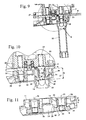
- FIGS. 9 and 10 show a arranged on the assembly tool 33, in the embodiment, a socket wrench.
- Fig. 10 shows, in the exemplary embodiment between the areas 27 and 30 of the dome 16, a shoulder 35 is formed.
- the tool 33 via the exposed portion 26 of the nut 10 and over the Dom 16 are pushed.
- Fig. 7 can slip off.
- the tool 33 can rest with its end face 34 on the shoulder 35 and be supported there.
- the nuts 10 have an outer side 46 facing away from the housing 2.
- the studs 23 have an external thread 45, which has a parallel to the longitudinal central axis 24 of the stud bolt 24 measured thread length h.
- Fig. 11 shows the housing cover 11 with nuts 10 disposed thereon in a position in which abut the end faces 28 of the nuts 10 on the bearing surfaces 17 of the dome 16. In this position, the retaining edge 20 on the sleeve-shaped portion 19 to the edge 29 of the housing cover 11 has a measured parallel to the longitudinal central axis 21 of the nut 10 distance f.
- the nuts 10 have an internal thread 44 with a thread length g. The thread length g is significantly smaller than a thread length h of the studs 23 in the exemplary embodiment.
- the thread length h of the threads 45 of the stud bolts 23, the thread length g of the internal threads 44 of the nuts 10 and the distance f are coordinated so that the nuts 10 completely from the stud bolts 23 are unscrewed when the housing cover 11 rests against the guide rail 8 and the guide rail 8 on the housing 2. This makes it possible to first completely loosen a nut 10 and then release the other nut 10.
- the distance f is at least as large as the contact length of the threaded connection between the threads 44 and 45 in the tightened state of the threaded connection, ie clamped held guide rail 8. In the embodiment corresponds to the contact length of the threaded connection of the thread length g of the internal thread 44 of the nut 10, da the internal thread 44 is fully screwed on the thread 45 of the stud bolt 23 in the tightened state.
- Fig. 12 shows an embodiment of a housing cover 51 in a partial sectional view.
- the housing cover 51 has two domes 56, of which in Fig. 12 one is shown.
- the design of the housing cover 51 substantially corresponds to the design of the housing cover 2.
- On the housing cover 51 a nut 10 is arranged.
- the nut 10 is formed according to the nut 10 of the preceding embodiment, wherein like reference numerals designate corresponding elements in all figures.
- the sleeve-shaped portion 19 of the nut 10 protrudes into an opening 22 of the housing cover 51. At the opening 22, an edge 29 is formed, which is engaged behind by a retaining edge 20 of the sleeve-shaped portion 19.
- the dome 51 has a first region 57 which adjoins the support surface 17 of the dome 56 for the nut 10.
- the first region 57 has a height i, which may be greater than the height a of the first region 27 of the preceding embodiment.
- the height i is greater than 2 mm.
- the first region 57 extends as far as the bottom 41 of the depression 14.
- the edge 29 of the opening 22 is formed in the first region 57.
- the first region 57 thus serves both as an area over which the tool 33 can be pushed, and for the captive fixing of the nut 10 on the retaining rim 20.
- the axial length of the region 57 is thereby used twice, so that overall a small overall width of Housing cover 51 and a small distance k ( Fig. 10 ) between the guide rail 8 and outer side 64 of the nut 10 can be achieved.
- the first region 57 has an outer diameter b which is smaller than the wrench size S of the nut 10 (FIG. Fig. 7 ).
- the first region 57 has an annular cross-section. When deviating from the circular shape cross-sectional shape is a maximum distance d of the outer periphery 32 of the first portion 57 is smaller than half the wrench size S of the nut 10th
Landscapes
- Engineering & Computer Science (AREA)
- Mechanical Engineering (AREA)
- Life Sciences & Earth Sciences (AREA)
- Wood Science & Technology (AREA)
- Forests & Forestry (AREA)
- Grinding-Machine Dressing And Accessory Apparatuses (AREA)
- Connection Of Plates (AREA)
- Sawing (AREA)
- Mounting Of Bearings Or Others (AREA)
Abstract
Description
- Die Erfindung betrifft ein handgeführtes Arbeitsgerät der im Oberbegriff des Anspruchs 1 angegebenen Gattung.
- Aus der
DE 10 2006 037 329 A1 ist ein handgeführtes Arbeitsgerät, nämlich eine handgeführte Kettensäge bekannt, deren Kettenraddeckel über unverlierbar gehaltene Muttern am Gehäuse fixiert ist. Die Oberfläche des Kettenraddeckels ist im Bereich der Muttern eben ausgebildet, und die Muttern sind als Bundmuttern ausgeführt. Dadurch ergibt sich eine große Auflagefläche der Mutter am Kettenraddeckel. Die Außenseite der Bundmutter ist aufgrund der Höhe der Schlüsselflächen und des Bunds vergleichsweise weit von der Auflagefläche der Mutter am Kettenraddeckel beabstandet, und es ergibt sich eine große Baubreite der Mutter. - Der Erfindung liegt die Aufgabe zugrunde, ein handgeführtes Arbeitsgerät der gattungsgemäßen Art zu schaffen, bei dem ein sicheres Festdrehen und Lösen der Befestigungselemente auch bei geringer Erstreckung der Schlüsselflächen des Befestigungselements möglich ist.
- Diese Aufgabe wird durch ein handgeführtes Arbeitsgerät mit den Merkmalen des Anspruchs 1 gelöst.
- Es ist vorgesehen, dass der Gehäusedeckel einen an der Gehäusedeckelaußenseite nach außen ragenden Dom besitzt, der eine Auflagefläche für das Befestigungselement bildet und durch den sich die Öffnung erstreckt. Der maximale radiale Abstand des Außenumfangs des Doms zur Längsmittelachse eines Stehbolzens des Arbeitsgeräts ist dabei an der Auflagefläche und in einem an die Auflagefläche angrenzenden ersten Bereich höchstens so groß wie die halbe Schlüsselweite der Schlüsselflächen des Befestigungselements. Dadurch kann ein Werkzeug zum Festdrehen und Lösen des Befestigungselements über den ersten Bereich des Doms geschoben werden. Dadurch ist ein Abrutschen des Werkzeugs von den Schlüsselflächen des Befestigungselements auch dann vermieden, wenn die Schlüsselflächen in Richtung der Längsmittelachse des Stehbolzens vergleichsweise kurz ausgebildet sind. Bei vergleichsweise niedriger Ausbildung der Schlüsselflächen kann die Erstreckung des Arbeitsgeräts in Richtung der Längsmittelachse des Stehbolzens, bei einer Motorsäge insbesondere die Baubreite der Motorsäge, verringert werden. Ist das Arbeitsgerät eine Motorsäge, so kann der seitliche Abstand zwischen der Sägekette und der Gehäusedeckelaußenseite bzw. der Außenseite der Befestigungselemente verringert werden, so dass mit der Motorsäge näher an einem Hindernis geschnitten werden kann. Der Begriff "radial" bezeichnet dabei die radiale Richtung zur Längsmittelachse des Stehbolzens.
- Der an der Gehäusedeckelaußenseite angeordnete Abschnitt des Befestigungselements ist in einer Draufsicht in Richtung der Längsmittelachse des Stehbolzens vorteilhaft von einer Umfangskontur begrenzt, die die Schlüsselflächen besitzt, und der Dom liegt zumindest an der Auflagefläche und in dem an die Auflagefläche angrenzenden ersten Bereich in einer Draufsicht in Richtung der Längsmittelachse des Stehbolzens innerhalb der von der Umfangskontur umschlossenen Fläche. Dadurch kann ein Werkzeug, das an den Schlüsselflächen angreift, über den ersten Bereich des Doms geschoben werden. Dadurch ist ein Abrutschen des Werkzeugs von den Schlüsselflächen auch bei geringer Höhe der Schlüsselflächen vermieden. Die Höhe der Schlüsselflächen ist dabei parallel zur Längsmittelachse des Stehbolzens gemessen. Vorteilhaft sind die Schlüsselflächen an einem Außensechskant des Befestigungselements ausgebildet. Der an der Gehäusedeckelaußenseite angeordnete Abschnitt des Befestigungselements ist in einer Draufsicht in Richtung der Längsmittelachse des Stehbolzens von dem Außensechskant begrenzt, und der Dom liegt zumindest an der Auflagefläche und in dem an die Auflagefläche angrenzenden ersten Bereich in der Draufsicht in Richtung der Längsmittelachse des Stehbolzens innerhalb des Außensechskants.
- Vorteilhaft beträgt die Höhe des an die Auflagefläche angrenzenden Bereichs des Doms mindestens 2 mm. Die Höhe des an die Auflagefläche angrenzenden Bereichs des Doms beträgt vorteilhaft mindestens 3 mm, vorzugsweise mindestens 4 mm. Dadurch kann das Werkzeug 2 mm, insbesondere 3 mm, vorzugsweise mindestens 4 mm über den Dom geschoben werden. Ein Abrutschen des Werkzeugs von den Schlüsselflächen ist dadurch sicher vermieden. Die Schlüsselflächen können dadurch vergleichsweise niedrig ausgebildet werden. Die parallel zur Längsmittelachse des Stehbolzens gemessene Höhe der Schlüsselflächen beträgt vorteilhaft weniger als 10 mm, insbesondere weniger als 8 mm. Bevorzugt beträgt die parallel zur Längsmittelachse des Stehbolzens gemessene Höhe der Schlüsselflächen 4 mm bis 6 mm. Dadurch kann eine sehr geringe Baubreite des Gehäusedeckels und des daran angeordneten Befestigungselements erreicht werden.
- Der Gehäusedeckel ist insbesondere aus Metall, und die am Dom ausgebildete Auflagefläche ist spanend bearbeitet. Dadurch können ausreichend hohe Anpresskräfte zwischen dem Befestigungselement und der Auflagefläche erreicht werden, auch wenn die Kontaktfläche aufgrund des verringerten maximalen Abstandes des Außenumfangs des Doms zur Längsmitteachse des Stehbolzens verringert ist. Der Gehäusedeckel besitzt vorteilhaft eine Außenschicht auf dem Metall. Die Außenschicht kann beispielsweise eine Lackierung oder eine Beschichtung oder dergleichen sein. Vorteilhaft erstreckt sich die Außenschicht nicht auf die Auflagefläche. Bevorzugt ist die Auflagefläche nach dem Aufbringen der Außenschicht spanend bearbeitet, so dass sich eine definierte, ebene Auflagefläche ergibt. Die Schlüsselflächen grenzen vorteilhaft an eine Stirnseite des Befestigungselements an, die an der Auflagefläche anliegt. Die Schlüsselflächen erstrecken sich demnach bis an die Auflagefläche, so dass sich eine möglichst große axiale Erstreckung der Schlüsselflächen ergibt.
- Vorteilhaft ist das Befestigungselement in der Öffnung des Gehäusedeckels unverlierbar gehalten. Auch bei vollständig von dem Stehbolzen abgeschraubtem Befestigungselement lässt sich das Befestigungselement dadurch nicht von dem Gehäusedeckel abnehmen, sondern ist am Gehäusedeckel gehalten. Vorteilhaft besitzt das Befestigungselement einen in die Öffnung ragenden Halterand, der einen Rand der Öffnung hintergreift. Der Halterand hält das Befestigungselement auch dann am Gehäusedeckel, wenn das Befestigungselement vollständig von dem Stehbolzen abgeschraubt ist. Der Rand der Öffnung ist vorteilhaft in dem Dom ausgebildet. Aufgrund der Verliersicherung des Befestigungselements an dem Gehäusedeckel über einen Halterand, der einen Rand des Gehäusedeckels hintergreift, wird eine vergleichsweise große Baubreite des Gehäusedeckels in diesem Bereich benötigt, um die axiale Relativbewegung des Befestigungselements gegenüber dem Gehäusedeckel beim Befestigen und Lösen des Befestigungselements zu ermöglichen. Gleichzeitig wird eine ausreichend große Aufschublänge für ein Werkzeug zum Verdrehen des Befestigungselements benötigt. Aufgrund des ersten Bereichs des Doms, über den ein Werkzeug zum Lösen oder Festziehen des Befestigungselements geschoben werden kann, kann die Baubreite des Gehäusedeckels reduziert werden, da die in axialer Richtung gemessene Höhe des ersten Bereichs sowohl als axiale Länge für die Verliersicherung des Befestigungselements als auch als Aufschublänge für ein Werkzeug genutzt wird. Die axiale Länge ist dabei die in Richtung der Längsmittelachse des Stehbolzens gemessene Länge.
- Bevorzugt ist der Rand der Öffnung in einem zweiten Bereich des Doms angeordnet, dessen Außendurchmesser größer als die Schlüsselweite der Schlüsselflächen ist. Dadurch kann ein ausreichend großer Außendurchmesser für den Rand erreicht werden. Um die Baubreite des Gehäusedeckels zu verringern, kann jedoch auch vorgesehen sein, dass der Rand der Öffnung in dem an die Auflagefläche angrenzenden ersten Bereich des Doms angeordnet ist. Der Halterand ist vorteilhaft an einem in die Öffnung ragenden hülsenförmigen Abschnitt des Befestigungselements ausgebildet. Um ein einfaches Abnehmen des Gehäusedeckels zu erreichen, sind der Abstand zwischen dem Halterand und dem Rand bei geklemmt gehaltener Werkzeugeinheit, die Gewindelänge des Befestigungselements und die Gewindelänge des Stehbolzens vorteilhaft so aufeinander abgestimmt, dass das Befestigungselement bei zwischen Gehäuse und Gehäusedeckel geklemmt gehaltener Werkzeugeinheit vollständig vom Gewinde des Stehbolzens abgeschraubt werden kann. Zum vollständigen Lösen des Befestigungselements muss der Gehäusedeckel dadurch seine Position nicht ändern. Insbesondere bei einer Befestigung des Gehäusedeckels über zwei Befestigungselemente kann dadurch ein Befestigungselement vollständig gelöst werden, bevor das zweite Befestigungselement gelöst wird. Dadurch ergibt sich eine einfache Handhabung.
- Bevorzugt ist der Gehäusedeckel ein Kettenraddeckel, und die Werkzeugeinheit umfasst eine zwischen dem Kettenraddeckel und dem Gehäuse geklemmt gehaltene Führungsschiene. Die Werkzeugeinheit kann jedoch auch ein anderes Werkzeug, insbesondere eine Schleifscheibe umfassen.
- Ein Ausführungsbeispiel der Erfindung wird im Folgenden anhand der Zeichnung erläutert. Es zeigen:
- Fig. 1
- eine perspektivische Darstellung einer Motorsäge,
- Fig. 2
- eine perspektivische Darstellung eines Gehäusedeckels der Motorsäge aus
Fig. 1 mit daran angeordneten Befestigungselementen, - Fig. 3
- eine Explosionsdarstellung von Gehäusedeckel und Befestigungselementen,
- Fig. 4
- eine ausschnittsweise Seitenansicht der Motorsäge,
- Fig. 5
- einen Schnitt entlang der Linie V-V in
Fig. 4 , - Fig. 6
- eine vergrößerte Darstellung des Bereichs VI aus
Fig. 5 , - Fig. 7
- eine vergrößerte Draufsicht auf die Befestigungselemente am Gehäusedeckel,
- Fig. 8
- eine vergrößerte Schnittdarstellung durch einen Dom des Gehäusedeckels,
- Fig. 9
- eine Schnittdarstellung entsprechend
Fig. 6 mit an einem Befestigungselement angeordnetem Werkzeug, - Fig. 10
- den Ausschnitt X aus
Fig. 9 in vergrößerter Darstellung, - Fig. 11
- einen Schnitt durch den Gehäusedeckel mit daran angeordneten Befestigungselementen,
- Fig. 12
- eine ausschnittsweise Schnittdarstellung eines Ausführungsbeispiels eines Gehäusedeckels.
-
Fig. 1 zeigt als Ausführungsbeispiel für ein Arbeitsgerät eine handgeführte Motorsäge 1. Die Motorsäge 1 besitzt ein Gehäuse 2, an dem ein hinterer Handgriff 3 sowie ein Griffbügel 4 zum Führen der Motorsäge 1 im Betrieb festgelegt sind. Am hinteren Handgriff 3 sind ein Bedienhebel 6 sowie eine Bedienhebelsperre 7 schwenkbar gelagert. Am Gehäuse 2 ist eine Werkzeugeinheit 39 festgelegt, die eine Führungsschiene 8 und eine an der Führungsschiene 8 umlaufend angeordnete Sägekette 9 umfasst. Auch eine anders aufgebaute Werkzeugeinheit 39 kann vorgesehen sein. Am Gehäuse 2 ist ein Handschutzbügel 5 angeordnet, der im Ausführungsbeispiel schwenkbar am Gehäuse 2 gelagert ist und zum Auslösen einer nicht gezeigten Kettenbremsvorrichtung dient. - Im Gehäuse 2 ist ein Antriebsmotor 12 angeordnet, der vorteilhaft als Verbrennungsmotor ausgebildet ist. Der Antriebsmotor 12 kann jedoch auch ein über Kabel oder einen Akku angetriebener Elektromotor sein. Das Gehäuse 2 ist das Motorgehäuse der Motorsäge 1. Der Antriebsmotor 12 treibt ein Kettenrad 15 rotierend an, das seinerseits die Sägekette 9 antreibt. Das Kettenrad 15 ist von einem Gehäusedeckel 11 abgedeckt. Der Gehäusedeckel 11 ist ein Kettenraddeckel. Der Gehäusedeckel 11 besitzt eine dem Gehäuse 2 abgewandte Gehäusedeckelaußenseite 13, an der zwei Muttern 10 zur Befestigung des Gehäusedeckels 11 am Gehäuse 2 angeordnet sind. Die Führungsschiene 8 ist zwischen dem Gehäusedeckel 11 und dem Gehäuse 2 geklemmt gehalten.
- Wie
Fig. 2 zeigt, besitzt der Gehäusedeckel 11 an seiner Gehäusedeckelaußenseite 13 zwei Längsstege 40, die eine Auflagefläche für den Gehäusedeckel 11 an einem Werkstück, beispielsweise einem zu fällenden Baum bilden. Zwischen den beiden Längsstegen 40 ist eine Vertiefung 14 an der Gehäusedeckelaußenseite 13 gebildet, in der die Muttern 10 angeordnet sind. WieFig. 2 zeigt, besitzt der Gehäusedeckel 11 an der Gehäuseaußenseite 13 nach außen ragende Dome 16, an denen die Muttern 10 aufliegen. Die Dome 16 sind dabei in der Vertiefung 14 angeordnet. Die Muttern 10 sind vorteilhaft weitgehend, insbesondere vollständig in der Vertiefung 14 angeordnet. Dadurch kann der Gehäusedeckel 11 an den Längsstegen 40 an einem Werkstück entlanggeführt werden, ohne dass sich das Werkstück an den Muttern 10 verhaken kann. Im Ausführungsbeispiel sind zwei Muttern 10 zur Befestigung des Gehäusedeckels 11 am Gehäuse 2 vorgesehen. Es kann jedoch auch nur eine einzige Mutter 10 vorgesehen sein. - Wie
Fig. 2 zeigt, besitzt der Gehäusedeckel 11 Befestigungsöffnungen 42 für einen Krallenanschlag. Das Gehäuse 2 kann weitere Befestigungsöffnungen 43 für einen weiteren Krallenanschlag aufweisen, wieFig. 4 zeigt. - Wie
Fig. 3 zeigt, umgeben die Dome 16 jeweils eine Öffnung 22. Die Vertiefung 14 des Gehäusedeckels 11 besitzt einen Boden 41, von dem sich die Dome 16 erheben. Die Muttern 10 besitzen jeweils einen ersten Abschnitt 26, der an der Gehäusedeckelaußenseite 13 angeordnet ist. Dieser erste Abschnitt 26 weist an seinem Außenumfang Schlüsselflächen 18 auf. Im Ausführungsbeispiel ist der Außenumfang des ersten Abschnitts 26 als Außensechskant ausgebildet. Auch eine beliebige andere regelmäßige oder unregelmäßige Kontur der Außenseite des ersten Abschnitts 26 kann jedoch vorteilhaft sein. Die Muttern 10 besitzen außerdem jeweils einen zweiten, hülsenförmigen Abschnitt 19, der in die Öffnung 22 ragt. An dem dem ersten Abschnitt 26 abgewandten Ende des hülsenförmigen, zweiten Abschnitts 19 ist jeweils ein radial nach außen ragender Halterand 20 an den hülsenförmigen Abschnitten 19 vorgesehen. Die Muttern 10 besitzen jeweils eine Längsmittelachse 21. An den Domen 16 ist eine der Unterseite der ersten Abschnitte 26 zugewandte Auflagefläche 17 ausgebildet. Im Ausführungsbeispiel sind die Auflageflächen 17 als Kreisringflächen ausgebildet. - Wie
Fig. 4 zeigt, besitzen die Muttern 10 eine Schlüsselweite S, die dem Abstand zweier einander zugeordneter, gegenüberliegender Schlüsselflächen 18 entspricht. Besitzt die Mutter 10 eine andere Form, so ist die Schlüsselweite S der doppelte Radius eines Inkreises der Außenkontur an den Schlüsselflächen 18, wobei der Mittelpunkt des Inkreises auf der Längsmittelachse 21 der Mutter 10 liegt. - Wie
Fig. 5 schematisch zeigt, ist das Kettenrad 15 von einer Antriebswelle 38 angetrieben. Die Antriebswelle 38 ist vorteilhaft über eine Fliehkraftkupplung mit einer Kurbelwelle des als Verbrennungsmotor gebildeten Antriebsmotors 12 verbunden. WieFig. 5 auch zeigt, sind ins Gehäuse 2 zwei Stehbolzen 23 eingeschraubt, die jeweils mit einem Bund 36 an der Außenseite des Gehäuses 2 anliegen. Der nach außen ragende Bereich der Stehbolzen 23 ragt durch die Öffnungen 22 des Gehäusedeckels 11. Die Muttern 10 sind jeweils auf die Stehbolzen 23 aufgeschraubt. Im Ausführungsbeispiel schließt das nach außen ragende, freie Ende 25 der Stehbolzen 23 etwa bündig mit der Außenseite der Muttern 10 ab. WieFig. 5 zeigt, liegen die Muttern 10 weitgehend innerhalb der Vertiefung 14. Die Führungsschiene 8 besitzt eine Öffnung 37, die als Langloch ausgebildet ist und durch die die Stehbolzen 23 ragen. - Die Stehbolzen 23 besitzen jeweils eine Längsmittelachse 24, die in montiertem Zustand des Gehäusedeckels 11 mit der Längsmittelachse 21 der Muttern 10 zusammenfällt.
Fig. 6 zeigt die Gestaltung der Dome 16 im Einzelnen. Die Dome 16 besitzen jeweils einen ersten Bereich 27, der an die Auflageflächen 17 anschließt. In dem ersten Bereich 27 besitzen die Dome 16 einen Außendurchmesser b. Der Außendurchmesser b entspricht dabei höchstens der Schlüsselweite S der Mutter 10 (Fig. 7 ). Im Ausführungsbeispiel sind die ersten Bereiche 27 mit kreisringförmigem Querschnitt ausgebildet, wie auchFig. 7 schematisch zeigt. Bei ungleichmäßiger Außenkontur ist ein maximaler Abstand d des Außenumfangs 32 des Doms 16 im ersten Bereich 27 höchstens so groß, also gleich groß oder kleiner, wie die halbe Schlüsselweite S. Die Muttern 10 besitzen an ihrem ersten, außenliegenden Abschnitt 26 eine Stirnseite 28, die an der Auflagefläche 17 der Dome 16 anliegt. WieFig. 6 auch zeigt, schließt an den ersten Bereich 27 ein zweiter Bereich 30 an der der Auflagefläche 17 abgewandten Seite an. Im zweiten Bereich 30 besitzen die Dome 16 einen Außendurchmesser c, der größer als die Schlüsselweite S ist. Dadurch wird eine erhöhte Stabilität erreicht. - Der erste Bereich 27 besitzt eine parallel zur Längsmittelachse 24 des Stehbolzens 23 gemessene Höhe a, die mindestens 2 mm beträgt. Vorteilhaft beträgt die Höhe a mindestens 3 mm, bevorzugt mindestens 4 mm. Die Höhe e der Schlüsselflächen 18 der Muttern 10 beträgt vorteilhaft weniger als 10 mm. Die Höhe e beträgt vorteilhaft weniger als 8 mm, bevorzugt etwa 4 mm bis etwa 6 mm.
- Die Muttern 10 sind am Gehäusedeckel 11 unverlierbar gehalten. Hierzu ist der Halterand 20 vorgesehen. Die Öffnungen 22 im Gehäusedeckel 10 besitzen jeweils einen Rand 29, den der radial nach außen ragende Halterand 20 bei vollständig von den Stehbolzen 23 abgeschraubten Muttern 10 hintergreift. Dadurch können die Muttern 10 nicht vom Gehäusedeckel 11 abgenommen werden, sondern sind auch bei vom Gehäuse 2 abgenommenem Gehäusedeckel 11 unverlierbar am Gehäusedeckel 11 gehalten.
- Wie
Fig. 8 zeigt, weist der Gehäusedeckel 11 eine Außenschicht 31 auf. Die Außenschicht 31 ist vorteilhaft eine Lackierung oder Beschichtung. An der Auflagefläche 17 ist keine Außenschicht 31 vorgesehen. Die Auflagefläche 17 ist vorteilhaft spanend bearbeitet, insbesondere nach dem Aufbringen der Außenschicht 31. Dadurch ergibt sich an der Auflagefläche 17 eine definierte, ebene Fläche. Dadurch wird eine definierte, ausreichend große Kontaktfläche zwischen der Auflagefläche 17 und der Stirnseite 28 der Mutter 10 erreicht. - Die
Figuren 9 und 10 zeigen ein an der Anordnung angeordnetes Werkzeug 33, im Ausführungsbeispiel ein Steckschlüssel. WieFig. 10 zeigt, ist im Ausführungsbeispiel zwischen den Bereichen 27 und 30 der Dome 16 ein Absatz 35 gebildet. Bis zum Absatz 35 kann das Werkzeug 33 über den freiliegenden Abschnitt 26 der Mutter 10 und über den Dom 16 geschoben werden. Dadurch ist auch bei geringer Höhe des freiliegenden Abschnitts 26 sichergestellt, dass das Werkzeug 33 beim Lösen oder Festdrehen der Mutter 10 nicht von den Schlüsselflächen 18 (Fig. 7 ) abrutschen kann. Das Werkzeug 33 kann dabei mit seiner Stirnseite 34 auf dem Absatz 35 aufliegen und sich dort abstützen. Die Muttern 10 besitzen eine dem Gehäuse 2 abgewandte Außenseite 46. Durch den ersten Bereich 27 des Doms 16 mit verringertem Durchmesser kann aufgrund der geringen benötigten Höhe der Muttern 10 ein geringer Abstand k der Außenseiten 46 der Muttern 10 zur Führungsschiene 8 erreicht werden. Die Stehbolzen 23 besitzen ein Außengewinde 45, das eine parallel zur Längsmittelachse 24 des Stehbolzens 24 gemessene Gewindelänge h besitzt. -
Fig. 11 zeigt den Gehäusedeckel 11 mit daran angeordneten Muttern 10 in einer Stellung, in der die Stirnseiten 28 der Muttern 10 an den Auflageflächen 17 der Dome 16 anliegen. In dieser Stellung besitzt der Halterand 20 am hülsenförmigen Abschnitt 19 zum Rand 29 des Gehäusedeckels 11 einen parallel zur Längsmittelachse 21 der Mutter 10 gemessenen Abstand f. Die Muttern 10 besitzen ein Innengewinde 44 mit einer Gewindelänge g. Die Gewindelänge g ist im Ausführungsbeispiel deutlich kleiner als eine Gewindelänge h der Stehbolzen 23. Die Gewindelänge h der Gewinde 45 der Stehbolzen 23, die Gewindelänge g der Innengewinde 44 der Muttern 10 und der Abstand f sind so aufeinander abgestimmt, dass die Muttern 10 vollständig von den Stehbolzen 23 abgeschraubt werden, wenn der Gehäusedeckel 11 an der Führungsschiene 8 und die Führungsschiene 8 am Gehäuse 2 anliegt. Dadurch ist es möglich, zuerst eine Mutter 10 vollständig zu lösen und anschließend die andere Mutter 10 zu lösen. Der Abstand f ist dabei mindestens so groß wie die Kontaktlänge der Gewindeverbindung zwischen den Gewinden 44 und 45 in angezogenem Zustand der Gewindeverbindung, also bei geklemmt gehaltener Führungsschiene 8. Im Ausführungsbeispiel entspricht die Kontaktlänge der Gewindeverbindung der Gewindelänge g des Innengewindes 44 der Mutter 10, da das Innengewinde 44 in angezogenem Zustand vollständig auf das Gewinde 45 des Stehbolzens 23 aufgeschraubt ist. -
Fig. 12 zeigt ein Ausführungsbeispiel eines Gehäusedeckels 51 in einer ausschnittsweisen Schnittdarstellung. Der Gehäusedeckel 51 besitzt zwei Dome 56, von denen inFig. 12 einer gezeigt ist. Die Gestaltung des Gehäusedeckels 51 entspricht im Wesentlichen der Gestaltung des Gehäusedeckels 2. Am Gehäusedeckel 51 ist eine Mutter 10 angeordnet. Die Mutter 10 ist entsprechend der Mutter 10 des vorangegangenen Ausführungsbeispiels ausgebildet, wobei gleiche Bezugszeichen in allen Figuren einander entsprechende Elemente bezeichnen. Der hülsenförmige Abschnitt 19 der Mutter 10 ragt in eine Öffnung 22 des Gehäusedeckels 51. An der Öffnung 22 ist ein Rand 29 ausgebildet, der von einem Halterand 20 des hülsenförmigen Abschnitts 19 hintergriffen wird. Der Dom 51 besitzt einen ersten Bereich 57, der an die Auflagefläche 17 des Doms 56 für die Mutter 10 angrenzt. Der erste Bereich 57 besitzt eine Höhe i, die größer sein kann als die Höhe a des ersten Bereichs 27 des vorangegangenen Ausführungsbeispiels. Die Höhe i ist größer als 2 mm. Der erste Bereich 57 erstreckt sich bis an den Boden 41 der Vertiefung 14. Dadurch kann das Werkzeug 33 am Gehäusedeckel 51 bis an den Boden 41 der Vertiefung 14 über eine Mutter 10 geschoben werden. Der Rand 29 der Öffnung 22 ist im ersten Bereich 57 ausgebildet. Der erste Bereich 57 dient damit sowohl als Bereich, über den das Werkzeug 33 geschoben werden kann, als auch zur unverlierbaren Fixierung der Mutter 10 am Halterand 20. Die axiale Länge des Bereichs 57 wird dadurch doppelt genutzt, so dass sich insgesamt eine geringe Baubreite des Gehäusedeckels 51 und ein geringer Abstand k (Fig. 10 ) zwischen Führungsschiene 8 und Außenseite 64 der Mutter 10 erreichen lässt. - Der erste Bereich 57 besitzt einen Außendurchmesser b, der kleiner als die Schlüsselweite S der Mutter 10 (
Fig. 7 ) ist. Im Ausführungsbeispiel besitzt der erste Bereich 57 einen kreisringförmigen Querschnitt. Bei von der Kreisringform abweichender Querschnittsform ist ein maximaler Abstand d des Außenumfangs 32 des ersten Bereichs 57 kleiner als die halbe Schlüsselweite S der Mutter 10.
Claims (13)
- Handgeführtes Arbeitsgerät mit einem Gehäuse (2), an dem ein Gehäusedeckel (11, 51) festgelegt ist, wobei zwischen dem Gehäuse (2) und dem Gehäusedeckel (11, 51) eine Werkzeugeinheit (39) gehalten ist, wobei an dem Gehäuse (2) mindestens ein Stehbolzen (23) festgelegt ist, der durch eine Öffnung (22) des Gehäusedeckels (11, 51) ragt und der eine Längsmittelachse (24) besitzt, wobei auf das freie Ende (25) des Stehbolzens (23) ein Befestigungselement aufgeschraubt ist, das den Gehäusedeckel (11, 51) am Gehäuse (2) sichert, wobei der Gehäusedeckel (11, 51) eine dem Gehäuse (2) abgewandte Gehäusedeckelaußenseite (13) besitzt und wobei das Befestigungselement mindestens zwei einander zugeordnete, an der Gehäusedeckelaußenseite (13) angeordnete Schlüsselflächen (18) aufweist, dadurch gekennzeichnet, dass der Gehäusedeckel (11, 51) einen an der Gehäusedeckelaußenseite (13) nach außen ragenden Dom (16, 56) besitzt, der eine Auflagefläche (17) für das Befestigungselement bildet und durch den sich die Öffnung (22) erstreckt, und dass der maximale radiale Abstand (d) des Außenumfangs (32) des Doms (16, 56) zur Längsmittelachse (24) an der Auflagefläche (17) und in einem an die Auflagefläche (17) angrenzenden ersten Bereich (27, 57) höchstens so groß ist wie die halbe Schlüsselweite (S) der Schlüsselflächen (18) des Befestigungselements.
- Arbeitsgerät nach Anspruch 1,
dadurch gekennzeichnet, dass die Höhe (a, i) des an die Auflagefläche (17) angrenzenden Bereichs (27, 57) des Doms (16, 56) mindestens 2 mm beträgt. - Arbeitsgerät nach Anspruch 1 oder 2,
dadurch gekennzeichnet, dass die parallel zur Längsmittelachse (24) gemessene Höhe (e) der Schlüsselflächen (18) weniger als 10 mm beträgt. - Arbeitsgerät nach einem der Ansprüche 1 bis 3,
dadurch gekennzeichnet, dass der Gehäusedeckel (11, 51) aus Metall ist und dass die Auflagefläche (17) spanend bearbeitet ist. - Arbeitsgerät nach Anspruch 4,
dadurch gekennzeichnet, dass der Gehäusedeckel (11, 51) eine Außenschicht (31) auf dem Metall aufweist und dass die Außenschicht (31) sich nicht auf die Auflagefläche (17) erstreckt. - Arbeitsgerät nach einem der Ansprüche 1 bis 5,
dadurch gekennzeichnet, dass die Schlüsselflächen (18) an eine Stirnseite (28) des Befestigungselements angrenzen, die an der Auflagefläche (17) anliegt. - Arbeitsgerät nach einem der Ansprüche 1 bis 6,
dadurch gekennzeichnet, dass das Befestigungselement in der Öffnung (22) des Gehäusedeckels (11, 51) unverlierbar gehalten ist. - Arbeitsgerät nach Anspruch 7,
dadurch gekennzeichnet, dass das Befestigungselement einen in die Öffnung (22) ragenden Halterand (20) besitzt, der einen Rand (29) der Öffnung (22) hintergreift. - Arbeitsgerät nach Anspruch 8,
dadurch gekennzeichnet, dass der Rand (29) der Öffnung (22) in dem Dom (16, 56) ausgebildet ist. - Arbeitsgerät nach Anspruch 9,
dadurch gekennzeichnet, dass der Rand (29) der Öffnung (22) in einem zweiten Bereich (30) des Doms (16) angeordnet ist, dessen Außendurchmesser (c) größer als die Schlüsselweite (S) der Schlüsselflächen (18) ist. - Arbeitsgerät nach einem der Ansprüche 8 bis 10,
dadurch gekennzeichnet, dass der Halterand (20) an einem in die Öffnung (22) ragenden hülsenförmigen Abschnitt (19) des Befestigungselements ausgebildet ist. - Arbeitsgerät nach Anspruch 11,
dadurch gekennzeichnet, dass der Abstand (f) zwischen dem Halterand (20) und dem Rand (29), die Gewindelänge (g) des Befestigungselements und die Gewindelänge (h) des Stehbolzens (23) so aufeinander abgestimmt sind, dass das Befestigungselement bei zwischen Gehäuse (2) und Gehäusedeckel (11, 51) geklemmt gehaltener Werkzeugeinheit (39) vollständig vom Gewinde (45) des Stehbolzens (23) abgeschraubt werden kann. - Arbeitsgerät nach einem der Ansprüche 1 bis 12,
dadurch gekennzeichnet, dass der Gehäusedeckel (11, 51) ein Kettenraddeckel ist und dass die Werkzeugeinheit (39) eine zwischen dem Kettenraddeckel und dem Gehäuse (2) geklemmt gehaltene Führungsschiene (8) umfasst.
Priority Applications (5)
| Application Number | Priority Date | Filing Date | Title |
|---|---|---|---|
| EP15000308.5A EP3053717B1 (de) | 2015-02-03 | 2015-02-03 | Arbeitsgerät |
| BR102016000118-8A BR102016000118B1 (pt) | 2015-02-03 | 2016-01-05 | Aparelho de trabalho |
| RU2016102697A RU2698611C2 (ru) | 2015-02-03 | 2016-01-28 | Ручной рабочий инструмент |
| US15/011,575 US9993937B2 (en) | 2015-02-03 | 2016-01-31 | Power tool |
| CN201610075340.XA CN105835010B (zh) | 2015-02-03 | 2016-02-03 | 工作器械 |
Applications Claiming Priority (1)
| Application Number | Priority Date | Filing Date | Title |
|---|---|---|---|
| EP15000308.5A EP3053717B1 (de) | 2015-02-03 | 2015-02-03 | Arbeitsgerät |
Publications (2)
| Publication Number | Publication Date |
|---|---|
| EP3053717A1 true EP3053717A1 (de) | 2016-08-10 |
| EP3053717B1 EP3053717B1 (de) | 2020-06-10 |
Family
ID=52446187
Family Applications (1)
| Application Number | Title | Priority Date | Filing Date |
|---|---|---|---|
| EP15000308.5A Active EP3053717B1 (de) | 2015-02-03 | 2015-02-03 | Arbeitsgerät |
Country Status (5)
| Country | Link |
|---|---|
| US (1) | US9993937B2 (de) |
| EP (1) | EP3053717B1 (de) |
| CN (1) | CN105835010B (de) |
| BR (1) | BR102016000118B1 (de) |
| RU (1) | RU2698611C2 (de) |
Cited By (1)
| Publication number | Priority date | Publication date | Assignee | Title |
|---|---|---|---|---|
| US20160221208A1 (en) * | 2015-02-03 | 2016-08-04 | Andreas Stihl Ag & Co. Kg | Power Tool |
Families Citing this family (6)
| Publication number | Priority date | Publication date | Assignee | Title |
|---|---|---|---|---|
| USD790303S1 (en) * | 2015-08-06 | 2017-06-27 | Andreas Stihl Ag & Co. Kg | Cordless chainsaw |
| USD826021S1 (en) * | 2016-02-15 | 2018-08-21 | Andreas Stihl Ag & Co., Kg | Chain saw |
| EP4208322A4 (de) | 2020-09-04 | 2024-09-11 | Milwaukee Electric Tool Corporation | Kettensäge |
| EP4008491A1 (de) * | 2020-12-04 | 2022-06-08 | Hilti Aktiengesellschaft | Werkzeugmaschine mit einem ersten griff, einem zweiten griff und einem hauptkörper |
| CN115723013A (zh) * | 2021-09-01 | 2023-03-03 | 株式会社牧田 | 研磨工具 |
| SE2151238A1 (en) * | 2021-10-08 | 2023-04-09 | Husqvarna Ab | Chainsaws, methods of controlling chainsaws, and computer programs implementing such methods |
Citations (7)
| Publication number | Priority date | Publication date | Assignee | Title |
|---|---|---|---|---|
| US5565719A (en) * | 1992-08-14 | 1996-10-15 | Robert Bosch Gmbh | Hand power tool |
| EP0822036A1 (de) * | 1996-07-26 | 1998-02-04 | Ryobi North America, Inc. | Kupplung für einen trennbaren Baum für ein Kraftangetriebenes Werkzeug |
| WO2004078434A1 (en) * | 2003-03-06 | 2004-09-16 | Aktiebolaget Electrolux | Arrangement for a motordriven hand tool such as a chain saw |
| EP1602454A1 (de) * | 2004-05-25 | 2005-12-07 | BLACK & DECKER INC. | Anti-Slip Dachschindelgriff für Befestigungswerkzeug |
| DE102006037329A1 (de) | 2006-08-10 | 2008-02-14 | Andreas Stihl Ag & Co. Kg | Kettenraddeckelanordnung einer handgeführten Kettensäge |
| GB2462938A (en) * | 2008-08-29 | 2010-03-03 | Bosch Gmbh Robert | Hand-held power tool with opening and cover |
| US20110232110A1 (en) * | 2010-03-25 | 2011-09-29 | Wolf Guenter | Chain Saw |
Family Cites Families (9)
| Publication number | Priority date | Publication date | Assignee | Title |
|---|---|---|---|---|
| DE4142751C1 (en) * | 1991-12-23 | 1992-12-17 | Fa. Andreas Stihl, 7050 Waiblingen, De | Motor-driven chain-saw - has guide-plate with rear end held in place by fitting into shoulders on motor housing |
| GB0311852D0 (en) * | 2003-05-22 | 2003-06-25 | Westwind Air Bearings Ltd | Rotary tool holder assemblies |
| DE202004018583U1 (de) * | 2004-12-01 | 2006-04-06 | Rhodius Schleifwerkzeuge Gmbh & Co. Kg | Vorrichtung zum Trennen und Schleifen mit Vibrationsdämpfung und dafür geeignetes Werkzeug |
| DE102007045240B4 (de) * | 2007-09-21 | 2017-10-26 | Andreas Stihl Ag & Co. Kg | Motorsäge |
| JP5146912B2 (ja) * | 2008-05-23 | 2013-02-20 | 日立工機株式会社 | チェーンソー |
| DE102012010963A1 (de) * | 2012-05-31 | 2013-12-05 | Andreas Stihl Ag & Co. Kg | Arbeitsgerät mit Kettenraddeckel |
| JP6132626B2 (ja) * | 2013-03-29 | 2017-05-24 | 株式会社マキタ | 携帯作業機 |
| DE202013105469U1 (de) * | 2013-12-02 | 2015-03-03 | Makita Corporation | Befestigungsanordnung, tragbares Arbeitsgerät zum Befestigen eines ersten Gehäuseteils an einem zweiten Gehäuseteil |
| EP3053717B1 (de) * | 2015-02-03 | 2020-06-10 | Andreas Stihl AG & Co. KG | Arbeitsgerät |
-
2015
- 2015-02-03 EP EP15000308.5A patent/EP3053717B1/de active Active
-
2016
- 2016-01-05 BR BR102016000118-8A patent/BR102016000118B1/pt active IP Right Grant
- 2016-01-28 RU RU2016102697A patent/RU2698611C2/ru active
- 2016-01-31 US US15/011,575 patent/US9993937B2/en active Active
- 2016-02-03 CN CN201610075340.XA patent/CN105835010B/zh active Active
Patent Citations (7)
| Publication number | Priority date | Publication date | Assignee | Title |
|---|---|---|---|---|
| US5565719A (en) * | 1992-08-14 | 1996-10-15 | Robert Bosch Gmbh | Hand power tool |
| EP0822036A1 (de) * | 1996-07-26 | 1998-02-04 | Ryobi North America, Inc. | Kupplung für einen trennbaren Baum für ein Kraftangetriebenes Werkzeug |
| WO2004078434A1 (en) * | 2003-03-06 | 2004-09-16 | Aktiebolaget Electrolux | Arrangement for a motordriven hand tool such as a chain saw |
| EP1602454A1 (de) * | 2004-05-25 | 2005-12-07 | BLACK & DECKER INC. | Anti-Slip Dachschindelgriff für Befestigungswerkzeug |
| DE102006037329A1 (de) | 2006-08-10 | 2008-02-14 | Andreas Stihl Ag & Co. Kg | Kettenraddeckelanordnung einer handgeführten Kettensäge |
| GB2462938A (en) * | 2008-08-29 | 2010-03-03 | Bosch Gmbh Robert | Hand-held power tool with opening and cover |
| US20110232110A1 (en) * | 2010-03-25 | 2011-09-29 | Wolf Guenter | Chain Saw |
Cited By (2)
| Publication number | Priority date | Publication date | Assignee | Title |
|---|---|---|---|---|
| US20160221208A1 (en) * | 2015-02-03 | 2016-08-04 | Andreas Stihl Ag & Co. Kg | Power Tool |
| US9993937B2 (en) * | 2015-02-03 | 2018-06-12 | Andreas Stihl Ag & Co. Kg | Power tool |
Also Published As
| Publication number | Publication date |
|---|---|
| RU2698611C2 (ru) | 2019-08-28 |
| US20160221208A1 (en) | 2016-08-04 |
| BR102016000118B1 (pt) | 2022-02-15 |
| BR102016000118A2 (pt) | 2016-10-04 |
| RU2016102697A (ru) | 2017-08-02 |
| RU2016102697A3 (de) | 2019-06-20 |
| CN105835010A (zh) | 2016-08-10 |
| US9993937B2 (en) | 2018-06-12 |
| EP3053717B1 (de) | 2020-06-10 |
| CN105835010B (zh) | 2020-12-08 |
Similar Documents
| Publication | Publication Date | Title |
|---|---|---|
| EP3053717B1 (de) | Arbeitsgerät | |
| DE102010012748B4 (de) | Kettensäge | |
| DE2813025C2 (de) | Sicherheitsbolzen | |
| DE10316182A1 (de) | Handschleifmaschine mit Schutzhaube | |
| DE102006037329A1 (de) | Kettenraddeckelanordnung einer handgeführten Kettensäge | |
| EP2974945B1 (de) | Klappe für ein fahrzeug | |
| EP3971427B1 (de) | Verbindungssystem zum verbinden von mindestens zwei, insbesondere plattenartigen elementen; anordnung mit einem derartigen verbindungssystem | |
| DE69204073T2 (de) | Zusammenbau von rad und antriebskeil. | |
| DE102013110429A1 (de) | Kunststoff-Befestigungselement sowie Befestigungsanordnung hiermit | |
| DE3831807A1 (de) | Niederhaltevorrichtung | |
| DE102014115008A1 (de) | Vorrichtung zum positionsgerechten Befestigen einer Antennenanordnung an einer Fläche | |
| DE10355513B4 (de) | Distanzscheibe, die zum Gebrauch mit einer Bremsscheibe einschliesslich eines Sattels geeignet ist | |
| EP3197651A1 (de) | Arbeitsgerät | |
| DE3913898A1 (de) | Einrichtung zur axialen sicherung, zum verriegeln und zum drehverstellen der schutzhaube auf dem spannhals von handwerkzeugmaschinen | |
| DE2944833A1 (de) | Schleifwerkzeug | |
| EP3736093B1 (de) | Befestigungsvorrichtung zum befestigen eines kettensägenschwerts | |
| DE102017127270B3 (de) | Befestigungssystem zur Befestigung eines Werkzeugs an einer Werkzeugaufnahme sowie zugehöriger Werkzeugschlüssel | |
| EP0978663A1 (de) | Befestigungseinheit zur Befestigung eines Gegenstandes an einem Profilelement mit einem Längsschlitz | |
| EP4335590B1 (de) | Zwischenelement zum anordnen zwischen einer spannvorrichtung und einem untergrund und ein zwischenelement umfassender spannturm | |
| DE10219829A1 (de) | Vorrichtung zum Befestigen eines Abgaskrümmers | |
| EP3988803B1 (de) | Funktionseinheit mit befestigungselement und fixierelement | |
| DE3904450C2 (de) | ||
| EP0767336A2 (de) | Zentriervorrichtung für die Dichtung einer Flanschverbindung | |
| EP1121984B1 (de) | Zentrifuge mit einem Spannband als Montagemittel | |
| DE102007062251A1 (de) | Werkzeug |
Legal Events
| Date | Code | Title | Description |
|---|---|---|---|
| PUAI | Public reference made under article 153(3) epc to a published international application that has entered the european phase |
Free format text: ORIGINAL CODE: 0009012 |
|
| AK | Designated contracting states |
Kind code of ref document: A1 Designated state(s): AL AT BE BG CH CY CZ DE DK EE ES FI FR GB GR HR HU IE IS IT LI LT LU LV MC MK MT NL NO PL PT RO RS SE SI SK SM TR |
|
| AX | Request for extension of the european patent |
Extension state: BA ME |
|
| STAA | Information on the status of an ep patent application or granted ep patent |
Free format text: STATUS: REQUEST FOR EXAMINATION WAS MADE |
|
| 17P | Request for examination filed |
Effective date: 20170208 |
|
| RBV | Designated contracting states (corrected) |
Designated state(s): AL AT BE BG CH CY CZ DE DK EE ES FI FR GB GR HR HU IE IS IT LI LT LU LV MC MK MT NL NO PL PT RO RS SE SI SK SM TR |
|
| GRAP | Despatch of communication of intention to grant a patent |
Free format text: ORIGINAL CODE: EPIDOSNIGR1 |
|
| STAA | Information on the status of an ep patent application or granted ep patent |
Free format text: STATUS: GRANT OF PATENT IS INTENDED |
|
| RIC1 | Information provided on ipc code assigned before grant |
Ipc: B27B 17/00 20060101AFI20191210BHEP Ipc: B25F 5/02 20060101ALI20191210BHEP |
|
| INTG | Intention to grant announced |
Effective date: 20200108 |
|
| GRAS | Grant fee paid |
Free format text: ORIGINAL CODE: EPIDOSNIGR3 |
|
| GRAA | (expected) grant |
Free format text: ORIGINAL CODE: 0009210 |
|
| STAA | Information on the status of an ep patent application or granted ep patent |
Free format text: STATUS: THE PATENT HAS BEEN GRANTED |
|
| AK | Designated contracting states |
Kind code of ref document: B1 Designated state(s): AL AT BE BG CH CY CZ DE DK EE ES FI FR GB GR HR HU IE IS IT LI LT LU LV MC MK MT NL NO PL PT RO RS SE SI SK SM TR |
|
| REG | Reference to a national code |
Ref country code: GB Ref legal event code: FG4D Free format text: NOT ENGLISH |
|
| REG | Reference to a national code |
Ref country code: AT Ref legal event code: REF Ref document number: 1278835 Country of ref document: AT Kind code of ref document: T Effective date: 20200615 Ref country code: CH Ref legal event code: EP |
|
| REG | Reference to a national code |
Ref country code: DE Ref legal event code: R096 Ref document number: 502015012743 Country of ref document: DE |
|
| REG | Reference to a national code |
Ref country code: IE Ref legal event code: FG4D Free format text: LANGUAGE OF EP DOCUMENT: GERMAN |
|
| REG | Reference to a national code |
Ref country code: SE Ref legal event code: TRGR |
|
| REG | Reference to a national code |
Ref country code: LT Ref legal event code: MG4D |
|
| PG25 | Lapsed in a contracting state [announced via postgrant information from national office to epo] |
Ref country code: NO Free format text: LAPSE BECAUSE OF FAILURE TO SUBMIT A TRANSLATION OF THE DESCRIPTION OR TO PAY THE FEE WITHIN THE PRESCRIBED TIME-LIMIT Effective date: 20200910 Ref country code: GR Free format text: LAPSE BECAUSE OF FAILURE TO SUBMIT A TRANSLATION OF THE DESCRIPTION OR TO PAY THE FEE WITHIN THE PRESCRIBED TIME-LIMIT Effective date: 20200911 Ref country code: FI Free format text: LAPSE BECAUSE OF FAILURE TO SUBMIT A TRANSLATION OF THE DESCRIPTION OR TO PAY THE FEE WITHIN THE PRESCRIBED TIME-LIMIT Effective date: 20200610 Ref country code: LT Free format text: LAPSE BECAUSE OF FAILURE TO SUBMIT A TRANSLATION OF THE DESCRIPTION OR TO PAY THE FEE WITHIN THE PRESCRIBED TIME-LIMIT Effective date: 20200610 |
|
| REG | Reference to a national code |
Ref country code: NL Ref legal event code: MP Effective date: 20200610 |
|
| PG25 | Lapsed in a contracting state [announced via postgrant information from national office to epo] |
Ref country code: LV Free format text: LAPSE BECAUSE OF FAILURE TO SUBMIT A TRANSLATION OF THE DESCRIPTION OR TO PAY THE FEE WITHIN THE PRESCRIBED TIME-LIMIT Effective date: 20200610 Ref country code: BG Free format text: LAPSE BECAUSE OF FAILURE TO SUBMIT A TRANSLATION OF THE DESCRIPTION OR TO PAY THE FEE WITHIN THE PRESCRIBED TIME-LIMIT Effective date: 20200910 Ref country code: HR Free format text: LAPSE BECAUSE OF FAILURE TO SUBMIT A TRANSLATION OF THE DESCRIPTION OR TO PAY THE FEE WITHIN THE PRESCRIBED TIME-LIMIT Effective date: 20200610 Ref country code: RS Free format text: LAPSE BECAUSE OF FAILURE TO SUBMIT A TRANSLATION OF THE DESCRIPTION OR TO PAY THE FEE WITHIN THE PRESCRIBED TIME-LIMIT Effective date: 20200610 |
|
| PG25 | Lapsed in a contracting state [announced via postgrant information from national office to epo] |
Ref country code: NL Free format text: LAPSE BECAUSE OF FAILURE TO SUBMIT A TRANSLATION OF THE DESCRIPTION OR TO PAY THE FEE WITHIN THE PRESCRIBED TIME-LIMIT Effective date: 20200610 Ref country code: AL Free format text: LAPSE BECAUSE OF FAILURE TO SUBMIT A TRANSLATION OF THE DESCRIPTION OR TO PAY THE FEE WITHIN THE PRESCRIBED TIME-LIMIT Effective date: 20200610 |
|
| PG25 | Lapsed in a contracting state [announced via postgrant information from national office to epo] |
Ref country code: SM Free format text: LAPSE BECAUSE OF FAILURE TO SUBMIT A TRANSLATION OF THE DESCRIPTION OR TO PAY THE FEE WITHIN THE PRESCRIBED TIME-LIMIT Effective date: 20200610 Ref country code: EE Free format text: LAPSE BECAUSE OF FAILURE TO SUBMIT A TRANSLATION OF THE DESCRIPTION OR TO PAY THE FEE WITHIN THE PRESCRIBED TIME-LIMIT Effective date: 20200610 Ref country code: CZ Free format text: LAPSE BECAUSE OF FAILURE TO SUBMIT A TRANSLATION OF THE DESCRIPTION OR TO PAY THE FEE WITHIN THE PRESCRIBED TIME-LIMIT Effective date: 20200610 Ref country code: RO Free format text: LAPSE BECAUSE OF FAILURE TO SUBMIT A TRANSLATION OF THE DESCRIPTION OR TO PAY THE FEE WITHIN THE PRESCRIBED TIME-LIMIT Effective date: 20200610 Ref country code: ES Free format text: LAPSE BECAUSE OF FAILURE TO SUBMIT A TRANSLATION OF THE DESCRIPTION OR TO PAY THE FEE WITHIN THE PRESCRIBED TIME-LIMIT Effective date: 20200610 Ref country code: IT Free format text: LAPSE BECAUSE OF FAILURE TO SUBMIT A TRANSLATION OF THE DESCRIPTION OR TO PAY THE FEE WITHIN THE PRESCRIBED TIME-LIMIT Effective date: 20200610 Ref country code: PT Free format text: LAPSE BECAUSE OF FAILURE TO SUBMIT A TRANSLATION OF THE DESCRIPTION OR TO PAY THE FEE WITHIN THE PRESCRIBED TIME-LIMIT Effective date: 20201012 |
|
| PG25 | Lapsed in a contracting state [announced via postgrant information from national office to epo] |
Ref country code: IS Free format text: LAPSE BECAUSE OF FAILURE TO SUBMIT A TRANSLATION OF THE DESCRIPTION OR TO PAY THE FEE WITHIN THE PRESCRIBED TIME-LIMIT Effective date: 20201010 Ref country code: PL Free format text: LAPSE BECAUSE OF FAILURE TO SUBMIT A TRANSLATION OF THE DESCRIPTION OR TO PAY THE FEE WITHIN THE PRESCRIBED TIME-LIMIT Effective date: 20200610 Ref country code: SK Free format text: LAPSE BECAUSE OF FAILURE TO SUBMIT A TRANSLATION OF THE DESCRIPTION OR TO PAY THE FEE WITHIN THE PRESCRIBED TIME-LIMIT Effective date: 20200610 |
|
| REG | Reference to a national code |
Ref country code: DE Ref legal event code: R097 Ref document number: 502015012743 Country of ref document: DE |
|
| PLBE | No opposition filed within time limit |
Free format text: ORIGINAL CODE: 0009261 |
|
| STAA | Information on the status of an ep patent application or granted ep patent |
Free format text: STATUS: NO OPPOSITION FILED WITHIN TIME LIMIT |
|
| PG25 | Lapsed in a contracting state [announced via postgrant information from national office to epo] |
Ref country code: DK Free format text: LAPSE BECAUSE OF FAILURE TO SUBMIT A TRANSLATION OF THE DESCRIPTION OR TO PAY THE FEE WITHIN THE PRESCRIBED TIME-LIMIT Effective date: 20200610 |
|
| 26N | No opposition filed |
Effective date: 20210311 |
|
| PG25 | Lapsed in a contracting state [announced via postgrant information from national office to epo] |
Ref country code: SI Free format text: LAPSE BECAUSE OF FAILURE TO SUBMIT A TRANSLATION OF THE DESCRIPTION OR TO PAY THE FEE WITHIN THE PRESCRIBED TIME-LIMIT Effective date: 20200610 |
|
| PG25 | Lapsed in a contracting state [announced via postgrant information from national office to epo] |
Ref country code: MC Free format text: LAPSE BECAUSE OF FAILURE TO SUBMIT A TRANSLATION OF THE DESCRIPTION OR TO PAY THE FEE WITHIN THE PRESCRIBED TIME-LIMIT Effective date: 20200610 |
|
| REG | Reference to a national code |
Ref country code: BE Ref legal event code: MM Effective date: 20210228 |
|
| PG25 | Lapsed in a contracting state [announced via postgrant information from national office to epo] |
Ref country code: CH Free format text: LAPSE BECAUSE OF NON-PAYMENT OF DUE FEES Effective date: 20210228 Ref country code: LU Free format text: LAPSE BECAUSE OF NON-PAYMENT OF DUE FEES Effective date: 20210203 Ref country code: LI Free format text: LAPSE BECAUSE OF NON-PAYMENT OF DUE FEES Effective date: 20210228 |
|
| PG25 | Lapsed in a contracting state [announced via postgrant information from national office to epo] |
Ref country code: IE Free format text: LAPSE BECAUSE OF NON-PAYMENT OF DUE FEES Effective date: 20210203 |
|
| REG | Reference to a national code |
Ref country code: AT Ref legal event code: MM01 Ref document number: 1278835 Country of ref document: AT Kind code of ref document: T Effective date: 20210203 |
|
| PG25 | Lapsed in a contracting state [announced via postgrant information from national office to epo] |
Ref country code: AT Free format text: LAPSE BECAUSE OF NON-PAYMENT OF DUE FEES Effective date: 20210203 |
|
| PG25 | Lapsed in a contracting state [announced via postgrant information from national office to epo] |
Ref country code: BE Free format text: LAPSE BECAUSE OF NON-PAYMENT OF DUE FEES Effective date: 20210228 |
|
| PG25 | Lapsed in a contracting state [announced via postgrant information from national office to epo] |
Ref country code: HU Free format text: LAPSE BECAUSE OF FAILURE TO SUBMIT A TRANSLATION OF THE DESCRIPTION OR TO PAY THE FEE WITHIN THE PRESCRIBED TIME-LIMIT; INVALID AB INITIO Effective date: 20150203 |
|
| PG25 | Lapsed in a contracting state [announced via postgrant information from national office to epo] |
Ref country code: CY Free format text: LAPSE BECAUSE OF FAILURE TO SUBMIT A TRANSLATION OF THE DESCRIPTION OR TO PAY THE FEE WITHIN THE PRESCRIBED TIME-LIMIT Effective date: 20200610 |
|
| PG25 | Lapsed in a contracting state [announced via postgrant information from national office to epo] |
Ref country code: MK Free format text: LAPSE BECAUSE OF FAILURE TO SUBMIT A TRANSLATION OF THE DESCRIPTION OR TO PAY THE FEE WITHIN THE PRESCRIBED TIME-LIMIT Effective date: 20200610 |
|
| PG25 | Lapsed in a contracting state [announced via postgrant information from national office to epo] |
Ref country code: MT Free format text: LAPSE BECAUSE OF FAILURE TO SUBMIT A TRANSLATION OF THE DESCRIPTION OR TO PAY THE FEE WITHIN THE PRESCRIBED TIME-LIMIT Effective date: 20200610 |
|
| PG25 | Lapsed in a contracting state [announced via postgrant information from national office to epo] |
Ref country code: TR Free format text: LAPSE BECAUSE OF FAILURE TO SUBMIT A TRANSLATION OF THE DESCRIPTION OR TO PAY THE FEE WITHIN THE PRESCRIBED TIME-LIMIT Effective date: 20200610 |
|
| PGFP | Annual fee paid to national office [announced via postgrant information from national office to epo] |
Ref country code: SE Payment date: 20260223 Year of fee payment: 12 |
|
| PGFP | Annual fee paid to national office [announced via postgrant information from national office to epo] |
Ref country code: GB Payment date: 20260223 Year of fee payment: 12 |
|
| PGFP | Annual fee paid to national office [announced via postgrant information from national office to epo] |
Ref country code: DE Payment date: 20260220 Year of fee payment: 12 |
|
| PGFP | Annual fee paid to national office [announced via postgrant information from national office to epo] |
Ref country code: FR Payment date: 20260224 Year of fee payment: 12 |