EP1121984B1 - Zentrifuge mit einem Spannband als Montagemittel - Google Patents
Zentrifuge mit einem Spannband als Montagemittel Download PDFInfo
- Publication number
- EP1121984B1 EP1121984B1 EP01101688A EP01101688A EP1121984B1 EP 1121984 B1 EP1121984 B1 EP 1121984B1 EP 01101688 A EP01101688 A EP 01101688A EP 01101688 A EP01101688 A EP 01101688A EP 1121984 B1 EP1121984 B1 EP 1121984B1
- Authority
- EP
- European Patent Office
- Prior art keywords
- screw connection
- yoke
- centrifuge
- screw
- rotor
- Prior art date
- Legal status (The legal status is an assumption and is not a legal conclusion. Google has not performed a legal analysis and makes no representation as to the accuracy of the status listed.)
- Expired - Lifetime
Links
- 230000000881 depressing effect Effects 0.000 claims 1
- 238000002485 combustion reaction Methods 0.000 description 6
- 239000010687 lubricating oil Substances 0.000 description 5
- 230000000994 depressogenic effect Effects 0.000 description 3
- 239000003921 oil Substances 0.000 description 3
- 238000011109 contamination Methods 0.000 description 2
- 239000002184 metal Substances 0.000 description 2
- 239000002245 particle Substances 0.000 description 2
- 229910000639 Spring steel Inorganic materials 0.000 description 1
- 238000005452 bending Methods 0.000 description 1
- 238000004140 cleaning Methods 0.000 description 1
- 238000011161 development Methods 0.000 description 1
- 230000018109 developmental process Effects 0.000 description 1
- 239000012065 filter cake Substances 0.000 description 1
- 238000001914 filtration Methods 0.000 description 1
- 239000012530 fluid Substances 0.000 description 1
- 230000010354 integration Effects 0.000 description 1
- 238000004519 manufacturing process Methods 0.000 description 1
- 239000000463 material Substances 0.000 description 1
- 230000002787 reinforcement Effects 0.000 description 1
- 230000002269 spontaneous effect Effects 0.000 description 1
Images

Classifications
-
- B—PERFORMING OPERATIONS; TRANSPORTING
- B04—CENTRIFUGAL APPARATUS OR MACHINES FOR CARRYING-OUT PHYSICAL OR CHEMICAL PROCESSES
- B04B—CENTRIFUGES
- B04B7/00—Elements of centrifuges
- B04B7/08—Rotary bowls
-
- B—PERFORMING OPERATIONS; TRANSPORTING
- B04—CENTRIFUGAL APPARATUS OR MACHINES FOR CARRYING-OUT PHYSICAL OR CHEMICAL PROCESSES
- B04B—CENTRIFUGES
- B04B5/00—Other centrifuges
- B04B5/005—Centrifugal separators or filters for fluid circulation systems, e.g. for lubricant oil circulation systems
-
- B—PERFORMING OPERATIONS; TRANSPORTING
- B04—CENTRIFUGAL APPARATUS OR MACHINES FOR CARRYING-OUT PHYSICAL OR CHEMICAL PROCESSES
- B04B—CENTRIFUGES
- B04B7/00—Elements of centrifuges
- B04B7/02—Casings; Lids
-
- F—MECHANICAL ENGINEERING; LIGHTING; HEATING; WEAPONS; BLASTING
- F16—ENGINEERING ELEMENTS AND UNITS; GENERAL MEASURES FOR PRODUCING AND MAINTAINING EFFECTIVE FUNCTIONING OF MACHINES OR INSTALLATIONS; THERMAL INSULATION IN GENERAL
- F16B—DEVICES FOR FASTENING OR SECURING CONSTRUCTIONAL ELEMENTS OR MACHINE PARTS TOGETHER, e.g. NAILS, BOLTS, CIRCLIPS, CLAMPS, CLIPS OR WEDGES; JOINTS OR JOINTING
- F16B39/00—Locking of screws, bolts or nuts
- F16B39/02—Locking of screws, bolts or nuts in which the locking takes place after screwing down
- F16B39/10—Locking of screws, bolts or nuts in which the locking takes place after screwing down by a plate, spring, wire or ring immovable with regard to the bolt or object and mainly perpendicular to the axis of the bolt
- F16B39/108—Locking of screws, bolts or nuts in which the locking takes place after screwing down by a plate, spring, wire or ring immovable with regard to the bolt or object and mainly perpendicular to the axis of the bolt with a locking washer under the nut or bolt head having at least one tongue or lug folded against the nut or bolt head, or against the object itself
-
- Y—GENERAL TAGGING OF NEW TECHNOLOGICAL DEVELOPMENTS; GENERAL TAGGING OF CROSS-SECTIONAL TECHNOLOGIES SPANNING OVER SEVERAL SECTIONS OF THE IPC; TECHNICAL SUBJECTS COVERED BY FORMER USPC CROSS-REFERENCE ART COLLECTIONS [XRACs] AND DIGESTS
- Y10—TECHNICAL SUBJECTS COVERED BY FORMER USPC
- Y10S—TECHNICAL SUBJECTS COVERED BY FORMER USPC CROSS-REFERENCE ART COLLECTIONS [XRACs] AND DIGESTS
- Y10S411/00—Expanded, threaded, driven, headed, tool-deformed, or locked-threaded fastener
- Y10S411/924—Coupled nut and bolt
- Y10S411/926—Positive lock
- Y10S411/927—Side
-
- Y—GENERAL TAGGING OF NEW TECHNOLOGICAL DEVELOPMENTS; GENERAL TAGGING OF CROSS-SECTIONAL TECHNOLOGIES SPANNING OVER SEVERAL SECTIONS OF THE IPC; TECHNICAL SUBJECTS COVERED BY FORMER USPC CROSS-REFERENCE ART COLLECTIONS [XRACs] AND DIGESTS
- Y10—TECHNICAL SUBJECTS COVERED BY FORMER USPC
- Y10S—TECHNICAL SUBJECTS COVERED BY FORMER USPC CROSS-REFERENCE ART COLLECTIONS [XRACs] AND DIGESTS
- Y10S411/00—Expanded, threaded, driven, headed, tool-deformed, or locked-threaded fastener
- Y10S411/955—Locked bolthead or nut
- Y10S411/965—Locked bolthead or nut with retainer
- Y10S411/97—Resilient retainer
Definitions
- the invention relates to a centrifuge, which has a rotor and a housing, using a tensioning strap for assembling individual parts of the centrifuge comes, according to the preamble of claim 1.
- Centrifuges of the type described in the introduction are known.
- WO discloses 99/30827 a centrifuge that has a rotor made from different shells is.
- the housing consists of several shells.
- the bell housing is deep-drawn from sheet metal, while the housing base is a cast part.
- the housing base has an annular shoulder on which the bell is mounted, a ring-shaped sheet metal profile is used as a band in order to connect both components together connect.
- This band can, for example, by means of known screw connections be attached, e.g. in US-A-4492631.
- the principle used, which of pipe clamps is generally known.
- the centrifuge described can, for. B. for filtering lubricating oil of an internal combustion engine be applied in a motor vehicle.
- the straps described are used to ensure disassembly to ensure the individual centrifuge parts. Suffers from pollution with repeated opening and closing of the strap, however, the reliability of the Screw connection. Therefore, even when using self-locking nuts An undesired spontaneous loosening of the screw connection can occur because of the centrifuge rotor and the housing of an oscillating stress due to the rotor rotation or are exposed by the motor vehicle and the internal combustion engine. Solving the However, screw connection has unforeseeable consequences for the functioning of the Lube oil circuit of the internal combustion engine. In the worst case, the internal combustion engine fail due to lack of lubricating oil.
- the object of the invention is therefore a centrifuge with tensioning straps as a mounting means to create, which is reliable in its function over the entire service life.
- the centrifuge according to the invention has a housing in and in a known manner mounted rotor.
- the individual parts are due to the rotationally symmetrical shape executed like a shell and can therefore be used on the outer circumference can be attached to each other by tensioning straps.
- the centrifuge is characterized by the fact that the strap is screwed together is held together, which is locked by means of an elastic bracket becomes.
- the screw connection cannot therefore be opened are and therefore do not open automatically, because a rotational movement of the the partner forming the screw connection, i.e. the screw or the nut, is prevented becomes.
- the bracket can be elastically deformed to release the lock.
- the screw connection can be released in a known manner become.
- a corresponding tool such as a screwdriver or a Wrenches can be attached.
- the Screw connection has a firmly attached handle for loosening (e.g. a wing nut).
- the lock consists of a slit-shaped opening, the z. B. be designed as an elongated hole in the bracket can.
- This slot has parallel side edges, the part to be rotated Screw connection has at least two parallel active surfaces, which with said Margins are directly connected. Therefore, a twist is not that long possible as long as the described active areas communicate with the side edges. If the bracket is elastically deformed, in particular depressed, the active surfaces become the screw connection released so that the screw connection can be loosened can. The active surfaces can also serve to open the screw connection to enable.
- the movable part of the screw connection as Hexagon nut or hexagon screw can be made, the hexagon in a known Used for loosening with a wrench and three parallel active surface pairs provides which with the parallel side margins mentioned the slot in the bracket can communicate.
- An advantageous embodiment of the invention results when the screw connection as Clamping device is executed.
- Another option is to align the Screw connection at right angles to the strap. This advantageously leads to a very space-saving variant because the overlapping ends of the strap a thread can be provided in one end into which the screw is screwed becomes.
- the tension of the strap is specified in this variant.
- an advantageous variant of the invention provides that the bracket as the end of the strap is trained. This is a measure for component integration and continues to Finding a particularly space-saving solution.
- the tension band is regularly out Running spring steel or the like so that this material can be used simultaneously can come to create an elastic strap. In the bent end can then be introduced the slot mentioned above, which the locking for forms the screw connection.
- Advantageous variants of the invention provide that Tension strap preferred for connecting two housing shells or two rotor shells is used.
- the tensioning strap encompasses the shells described on its outer circumference, which also has shoulders, so that a positive Connection can be made. Alternatively, of course it is conceivable, a frictional connection while building up a sufficiently large tension to manufacture in the strap.
- FIG 1 the end of a strap 10a is shown. This end is bent and thus forms a bracket 11, which is used as a lock 12.
- the lock consists of a slot 13, with parallel side edges 14 (only one of these side edges is visible), the side edges communicating with a screw 15.
- the Screw 15 is inserted through a (not visible) hole in the strap.
- the bracket reinforcements 16 are attached, the z. B. by bending the Edges can be created.
- FIG. 1 Another variant of the tensioning strap is shown in FIG. Both ends of this Tension straps are initially angled at right angles to the screw at one end 15 and at the other end to take a mother 18.
- the screw can e.g. B. in known Way (not shown) by a square in one end against rotation be secured.
- the active surfaces 17, as shown in Figure 2 as a hexagon are attached to the nut 18 in the exemplary embodiment according to FIG.
- the associated end of the tension band is still the same as that in FIG. 1 and 2 variant shown as a bracket 11 with a slot, not shown executed.
- the bracket 11 In order to assemble the strap, the bracket 11 is depressed so that the nut 18 is rotatable. By tightening the screw connection consisting of screw 15 and Nut 18, a tension of the strap is built up at the same time. With enough great tension, the bracket 11 is released and in this way secures the mother 18. As already mentioned, the screw 15 is also secured against rotation, so that the screw connection cannot loosen automatically.
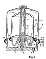
- FIG. 4 shows a centrifuge that has a housing 19 into which a rotor 20 is installed by means of slide bearings 21.
- the housing has a base 22 and a bell 23, which are held together with the aid of the tension band 10b according to FIG. 3.
- In the base there is an outlet 24 for the centrifuged oil and an inlet 25 for the centrifuging oil provided.
- the path of the oil through the centrifuge is through arrows indicated. It flows through a shaft 26 fixed to the housing and a central tube 27, which is designed as part of the rotor.
- On the center tube is a rotor jacket 28 and Nozzle body 29 stored.
- These two components form shells that together with one Intermediate plate 30 together with the aid of the tensioning band 10a according to the figures and 2 is held.
- Protected in the rotor jacket during operation through the intermediate plate, a filter cake, the centrifuge through the in the nozzle body provided nozzles 31 is driven.
- the centrifuged passes through the nozzles
Landscapes
- Engineering & Computer Science (AREA)
- General Engineering & Computer Science (AREA)
- Mechanical Engineering (AREA)
- Centrifugal Separators (AREA)
- Clamps And Clips (AREA)
Description
- Figur 1
- die perspektivische Ansicht des Endes eines Spannbandes mit niedergedrücktem Bügel,
- Figur 2
- das Spannband gemäß Figur 1 in geschlossenem Zustand in perspektivischer Ansicht,
- Figur 3
- die Variante eines Spannbandes mit Schraubverbindung als Spannvorrichtung in der Seitenansicht und
- Figur 4
- den Querschnitt durch eine Freistrahlzentrifuge zur Reinigung des Schmieröls einer Brennkraftmaschine.
Claims (7)
- Zentrifuge, aufweisend einen Rotor (20), der drehbar in einem Gehäuse (19) gelagert ist, wobei Rotor und Gehäuse aus einzelnen Schalen zusammengesetzt sind, die unter Verwendung mindestens einen Spannbandes (10a, b) aneinander befestigt sind, wobei das Spannband mittels einer Schraubverbindung (15, 18) zusammengehalten wird und wobei das Spannband einen elastischen Bügel (11) aufweist, dadurch gekennzeichnet, dass der elastische Bügel (11) in unverformtem Zustand mit der Schraubverbindung derart im Eingriff steht, dass eine Verdrehung der Schraubverbindung durch eine im Bügel angebrachte Arretierung (12) verhindert wird, und der Bügel zum Lösen der Schraubverbindung derart elastisch verformt werden kann, dass die Arretierung die Verdrehung der Schraube zulässt, wobei die Arretierung (12) aus einem Schlitz (13) besteht, welcher zwei parallele Seitenränder (14) aufweist, wobei der zu verdrehende Teil der Schraubverbindung parallele Wirkflächen (17) aufweist, die mit den Seitenrändem zur Verhinderung der Verdrehung im Eingriff stehen, und dass der Kontakt zwischen den Seitenrändern (14) und den Wirkflächen (17) durch die Verformung, insbesondere Niederdrücken, des Bügels aufgehoben werden kann.
- Zentrifuge nach Anspruch 1, dadurch gekennzeichnet, dass der zu verdrehende Teil der Schraubverbindung eine Mutter (18) mit einem als Sechskant ausgeführten Bereich als Wirkflächen (17) für die Seitenränder (14) ist.
- Zentrifuge nach Anspruch 1, dadurch gekennzeichnet, dass der zu verdrehende Teil der Schraubverbindung eine Schraube (18) mit einem als Sechskant ausgeführten Bereich als Wirkflächen (17) für die Seitenränder (14) ist.
- Zentrifuge nach einem der vorherigen Ansprüche, dadurch gekennzeichnet, dass die Schraubverbindung als Spannvorrichtung für das Spannband (10a) ausgeführt ist.
- Zentrifuge nach einem der vorherigen Ansprüche, dadurch gekennzeichnet, dass der Bügel (11) als Ende des Spannbandes (10a, b) ausgebildet ist, indem dieser umgebogen ist.
- Zentrifuge nach einem der vorherigen Ansprüche, dadurch gekennzeichnet, dass das Spannband (10a) den Rotor (20) umgreift.
- Zentrifuge nach einem der vorherigen Ansprüche, dadurch gekennzeichnet, dass das Spannband (10b) das Gehäuse (19) umgreift.
Applications Claiming Priority (2)
| Application Number | Priority Date | Filing Date | Title |
|---|---|---|---|
| US17926600P | 2000-01-31 | 2000-01-31 | |
| US179266P | 2000-01-31 |
Publications (3)
| Publication Number | Publication Date |
|---|---|
| EP1121984A2 EP1121984A2 (de) | 2001-08-08 |
| EP1121984A3 EP1121984A3 (de) | 2002-01-23 |
| EP1121984B1 true EP1121984B1 (de) | 2004-06-09 |
Family
ID=22655865
Family Applications (1)
| Application Number | Title | Priority Date | Filing Date |
|---|---|---|---|
| EP01101688A Expired - Lifetime EP1121984B1 (de) | 2000-01-31 | 2001-01-30 | Zentrifuge mit einem Spannband als Montagemittel |
Country Status (4)
| Country | Link |
|---|---|
| US (1) | US6558095B2 (de) |
| EP (1) | EP1121984B1 (de) |
| AT (1) | ATE268645T1 (de) |
| DE (1) | DE50102503D1 (de) |
Cited By (1)
| Publication number | Priority date | Publication date | Assignee | Title |
|---|---|---|---|---|
| CN105745024A (zh) * | 2014-04-18 | 2016-07-06 | 新兴精工株式会社 | 混合型离心分离机 |
Families Citing this family (1)
| Publication number | Priority date | Publication date | Assignee | Title |
|---|---|---|---|---|
| US20070124910A1 (en) * | 2005-12-07 | 2007-06-07 | Nesson Enterprises | Insertion tool for drywall hanger |
Family Cites Families (11)
| Publication number | Priority date | Publication date | Assignee | Title |
|---|---|---|---|---|
| US793088A (en) * | 1905-02-28 | 1905-06-27 | Matthew B Carter | Nut-lock. |
| GB190710334A (en) * | 1907-05-03 | 1907-12-31 | Richard Leonard Goulding | Improvements in Locking Washers for the Nuts of Bolts, Screws and the like. |
| US911063A (en) * | 1908-01-13 | 1909-02-02 | William M Offutt | Nut-lock. |
| US1134792A (en) * | 1914-05-26 | 1915-04-06 | Arthur C Will | Handle-lock. |
| US2190076A (en) * | 1938-05-05 | 1940-02-13 | Love Dumont | Locomotive wedge bolt nut lock device |
| GB705247A (en) * | 1952-11-19 | 1954-03-10 | Paul Emile Milleret | Improvements in or relating to metal hose clips |
| US2983384A (en) * | 1958-05-07 | 1961-05-09 | Charles A Winslow | Centrifuging and lubricant-purifying device |
| DE3146219A1 (de) * | 1981-11-21 | 1983-05-26 | Josef Dr.-Ing. 6719 Kirchheim Reisacher | "spannband zur verbindung von zwei im verbindungsstossbereich kreisfoermigen teilen" |
| US4492631A (en) * | 1982-01-19 | 1985-01-08 | Ae Plc | Centrifugal separator |
| DE3729372A1 (de) * | 1987-09-03 | 1989-03-16 | Rasmussen Gmbh | Schelle mit geschlitzten bandschlaufen zum einhaengen eines verschlusses |
| US5362111A (en) * | 1993-09-24 | 1994-11-08 | Vsi Corporation | Anti-rotation locking device for preventing separation of coupling nuts from fluid lines |
-
2001
- 2001-01-30 EP EP01101688A patent/EP1121984B1/de not_active Expired - Lifetime
- 2001-01-30 DE DE50102503T patent/DE50102503D1/de not_active Expired - Lifetime
- 2001-01-30 AT AT01101688T patent/ATE268645T1/de not_active IP Right Cessation
- 2001-01-31 US US09/774,508 patent/US6558095B2/en not_active Expired - Lifetime
Cited By (1)
| Publication number | Priority date | Publication date | Assignee | Title |
|---|---|---|---|---|
| CN105745024A (zh) * | 2014-04-18 | 2016-07-06 | 新兴精工株式会社 | 混合型离心分离机 |
Also Published As
| Publication number | Publication date |
|---|---|
| EP1121984A3 (de) | 2002-01-23 |
| US6558095B2 (en) | 2003-05-06 |
| US20030059273A1 (en) | 2003-03-27 |
| ATE268645T1 (de) | 2004-06-15 |
| EP1121984A2 (de) | 2001-08-08 |
| DE50102503D1 (de) | 2004-07-15 |
Similar Documents
| Publication | Publication Date | Title |
|---|---|---|
| DE19647742C2 (de) | Einrichtungs-Anziehvorrichtung für unverlierbare Schrauben | |
| EP1979634B1 (de) | Montageeinheit für die befestigungsöse eines gurtschlosses | |
| EP1681100B1 (de) | Brausekopf | |
| EP3032093B1 (de) | Befestigungsvorrichtung zur befestigung eines rotorblattes an einer rotornabe einer windkraftanlage | |
| EP1532372B1 (de) | Befestigungsanordnung | |
| EP3132146B1 (de) | Befestigungsvorrichtung | |
| DE202012009468U1 (de) | Verschlussbolzen und Verschlusselement hiermit | |
| EP0952053A2 (de) | Vorrichtung zur Befestigung einer Wischanlage an einem Fahrzeug | |
| DE19913022B4 (de) | Korbspule für Draht, insbesondere für Schweißdraht | |
| DE202011000570U1 (de) | Schubstangenspanner | |
| EP3433001B1 (de) | Filtereinrichtung für eine filteranlage eines kraftwagens | |
| EP1121984B1 (de) | Zentrifuge mit einem Spannband als Montagemittel | |
| EP2064454B1 (de) | Befestigungseinrichtung | |
| DE19743873C2 (de) | Befestigungsanordnung mit einer vormontierten Baueineheit | |
| WO2008116481A1 (de) | Zuganker und damit zusammengespannte modulanordnung | |
| WO2020035597A1 (de) | Dämpfungselement mit bajonettverschluss | |
| DE202006014999U1 (de) | Federspanner für Schraubenfedern | |
| DE2935423A1 (de) | Befestigungsvorrichtung fuer einen mehrspindelkopf einer bearbeitungsmaschine | |
| EP2095003B1 (de) | Blockverbinder für fluidleitungen | |
| DE2412597C2 (de) | Befestigungsvorrichtung | |
| DE3011848C2 (de) | ||
| EP1209343B1 (de) | Verschlussdeckel für ein Gehäuse | |
| DE2401300C2 (de) | Befestigungsanordnung, bestehend aus Mutter und Gewindebolzen | |
| DE19643751A1 (de) | Meßgerät | |
| EP0551873B1 (de) | Kunststoffbefestigungselement zum Aufdrücken auf einen Gewindebolzen |
Legal Events
| Date | Code | Title | Description |
|---|---|---|---|
| PUAI | Public reference made under article 153(3) epc to a published international application that has entered the european phase |
Free format text: ORIGINAL CODE: 0009012 |
|
| AK | Designated contracting states |
Kind code of ref document: A2 Designated state(s): AT BE CH CY DE DK ES FI FR GB GR IE IT LI LU MC NL PT SE TR |
|
| AX | Request for extension of the european patent |
Free format text: AL;LT;LV;MK;RO;SI |
|
| PUAL | Search report despatched |
Free format text: ORIGINAL CODE: 0009013 |
|
| RIC1 | Information provided on ipc code assigned before grant |
Free format text: 7B 04B 7/08 A, 7B 04B 7/02 B, 7B 04B 5/00 B, 7F 16L 23/08 B |
|
| AK | Designated contracting states |
Kind code of ref document: A3 Designated state(s): AT BE CH CY DE DK ES FI FR GB GR IE IT LI LU MC NL PT SE TR |
|
| AX | Request for extension of the european patent |
Free format text: AL;LT;LV;MK;RO;SI |
|
| 17P | Request for examination filed |
Effective date: 20020208 |
|
| AKX | Designation fees paid |
Free format text: AT BE CH CY DE DK ES FI FR GB GR IE IT LI LU MC NL PT SE TR |
|
| 17Q | First examination report despatched |
Effective date: 20030410 |
|
| GRAP | Despatch of communication of intention to grant a patent |
Free format text: ORIGINAL CODE: EPIDOSNIGR1 |
|
| RAP1 | Party data changed (applicant data changed or rights of an application transferred) |
Owner name: MANN + HUMMEL GMBH |
|
| GRAS | Grant fee paid |
Free format text: ORIGINAL CODE: EPIDOSNIGR3 |
|
| GRAA | (expected) grant |
Free format text: ORIGINAL CODE: 0009210 |
|
| AK | Designated contracting states |
Kind code of ref document: B1 Designated state(s): AT BE CH CY DE DK ES FI FR GB GR IE IT LI LU MC NL PT SE TR |
|
| PG25 | Lapsed in a contracting state [announced via postgrant information from national office to epo] |
Ref country code: IT Free format text: LAPSE BECAUSE OF FAILURE TO SUBMIT A TRANSLATION OF THE DESCRIPTION OR TO PAY THE FEE WITHIN THE PRESCRIBED TIME-LIMIT;WARNING: LAPSES OF ITALIAN PATENTS WITH EFFECTIVE DATE BEFORE 2007 MAY HAVE OCCURRED AT ANY TIME BEFORE 2007. THE CORRECT EFFECTIVE DATE MAY BE DIFFERENT FROM THE ONE RECORDED. Effective date: 20040609 Ref country code: TR Free format text: LAPSE BECAUSE OF FAILURE TO SUBMIT A TRANSLATION OF THE DESCRIPTION OR TO PAY THE FEE WITHIN THE PRESCRIBED TIME-LIMIT Effective date: 20040609 Ref country code: NL Free format text: LAPSE BECAUSE OF FAILURE TO SUBMIT A TRANSLATION OF THE DESCRIPTION OR TO PAY THE FEE WITHIN THE PRESCRIBED TIME-LIMIT Effective date: 20040609 Ref country code: FI Free format text: LAPSE BECAUSE OF FAILURE TO SUBMIT A TRANSLATION OF THE DESCRIPTION OR TO PAY THE FEE WITHIN THE PRESCRIBED TIME-LIMIT Effective date: 20040609 Ref country code: IE Free format text: LAPSE BECAUSE OF FAILURE TO SUBMIT A TRANSLATION OF THE DESCRIPTION OR TO PAY THE FEE WITHIN THE PRESCRIBED TIME-LIMIT Effective date: 20040609 |
|
| REG | Reference to a national code |
Ref country code: GB Ref legal event code: FG4D Free format text: NOT ENGLISH |
|
| REG | Reference to a national code |
Ref country code: CH Ref legal event code: EP |
|
| REF | Corresponds to: |
Ref document number: 50102503 Country of ref document: DE Date of ref document: 20040715 Kind code of ref document: P |
|
| REG | Reference to a national code |
Ref country code: IE Ref legal event code: FG4D Free format text: GERMAN |
|
| PG25 | Lapsed in a contracting state [announced via postgrant information from national office to epo] |
Ref country code: SE Free format text: LAPSE BECAUSE OF FAILURE TO SUBMIT A TRANSLATION OF THE DESCRIPTION OR TO PAY THE FEE WITHIN THE PRESCRIBED TIME-LIMIT Effective date: 20040909 Ref country code: DK Free format text: LAPSE BECAUSE OF FAILURE TO SUBMIT A TRANSLATION OF THE DESCRIPTION OR TO PAY THE FEE WITHIN THE PRESCRIBED TIME-LIMIT Effective date: 20040909 Ref country code: GR Free format text: LAPSE BECAUSE OF FAILURE TO SUBMIT A TRANSLATION OF THE DESCRIPTION OR TO PAY THE FEE WITHIN THE PRESCRIBED TIME-LIMIT Effective date: 20040909 |
|
| PG25 | Lapsed in a contracting state [announced via postgrant information from national office to epo] |
Ref country code: ES Free format text: LAPSE BECAUSE OF FAILURE TO SUBMIT A TRANSLATION OF THE DESCRIPTION OR TO PAY THE FEE WITHIN THE PRESCRIBED TIME-LIMIT Effective date: 20040920 |
|
| GBT | Gb: translation of ep patent filed (gb section 77(6)(a)/1977) |
Effective date: 20040917 |
|
| NLV1 | Nl: lapsed or annulled due to failure to fulfill the requirements of art. 29p and 29m of the patents act | ||
| REG | Reference to a national code |
Ref country code: IE Ref legal event code: FD4D |
|
| PG25 | Lapsed in a contracting state [announced via postgrant information from national office to epo] |
Ref country code: CY Free format text: LAPSE BECAUSE OF FAILURE TO SUBMIT A TRANSLATION OF THE DESCRIPTION OR TO PAY THE FEE WITHIN THE PRESCRIBED TIME-LIMIT Effective date: 20050130 Ref country code: LU Free format text: LAPSE BECAUSE OF NON-PAYMENT OF DUE FEES Effective date: 20050130 |
|
| PG25 | Lapsed in a contracting state [announced via postgrant information from national office to epo] |
Ref country code: MC Free format text: LAPSE BECAUSE OF NON-PAYMENT OF DUE FEES Effective date: 20050131 Ref country code: LI Free format text: LAPSE BECAUSE OF NON-PAYMENT OF DUE FEES Effective date: 20050131 Ref country code: AT Free format text: LAPSE BECAUSE OF NON-PAYMENT OF DUE FEES Effective date: 20050131 Ref country code: CH Free format text: LAPSE BECAUSE OF NON-PAYMENT OF DUE FEES Effective date: 20050131 Ref country code: BE Free format text: LAPSE BECAUSE OF NON-PAYMENT OF DUE FEES Effective date: 20050131 |
|
| ET | Fr: translation filed | ||
| PLBE | No opposition filed within time limit |
Free format text: ORIGINAL CODE: 0009261 |
|
| STAA | Information on the status of an ep patent application or granted ep patent |
Free format text: STATUS: NO OPPOSITION FILED WITHIN TIME LIMIT |
|
| 26N | No opposition filed |
Effective date: 20050310 |
|
| BERE | Be: lapsed |
Owner name: *MANN + HUMMEL G.M.B.H. Effective date: 20050131 |
|
| REG | Reference to a national code |
Ref country code: CH Ref legal event code: PL |
|
| BERE | Be: lapsed |
Owner name: *MANN + HUMMEL G.M.B.H. Effective date: 20050131 |
|
| PG25 | Lapsed in a contracting state [announced via postgrant information from national office to epo] |
Ref country code: PT Free format text: LAPSE BECAUSE OF NON-PAYMENT OF DUE FEES Effective date: 20041109 |
|
| REG | Reference to a national code |
Ref country code: FR Ref legal event code: PLFP Year of fee payment: 16 |
|
| REG | Reference to a national code |
Ref country code: FR Ref legal event code: PLFP Year of fee payment: 17 |
|
| REG | Reference to a national code |
Ref country code: FR Ref legal event code: PLFP Year of fee payment: 18 |
|
| REG | Reference to a national code |
Ref country code: DE Ref legal event code: R081 Ref document number: 50102503 Country of ref document: DE Owner name: MANN+HUMMEL GMBH, DE Free format text: FORMER OWNER: MANN + HUMMEL GMBH, 71638 LUDWIGSBURG, DE |
|
| PGFP | Annual fee paid to national office [announced via postgrant information from national office to epo] |
Ref country code: DE Payment date: 20200121 Year of fee payment: 20 Ref country code: GB Payment date: 20200123 Year of fee payment: 20 |
|
| PGFP | Annual fee paid to national office [announced via postgrant information from national office to epo] |
Ref country code: FR Payment date: 20200121 Year of fee payment: 20 |
|
| REG | Reference to a national code |
Ref country code: DE Ref legal event code: R071 Ref document number: 50102503 Country of ref document: DE |
|
| REG | Reference to a national code |
Ref country code: GB Ref legal event code: PE20 Expiry date: 20210129 |
|
| PG25 | Lapsed in a contracting state [announced via postgrant information from national office to epo] |
Ref country code: GB Free format text: LAPSE BECAUSE OF EXPIRATION OF PROTECTION Effective date: 20210129 |