EP3053554A1 - Dispositif de traitement de plaies par pression négative à incision fermée - Google Patents
Dispositif de traitement de plaies par pression négative à incision fermée Download PDFInfo
- Publication number
- EP3053554A1 EP3053554A1 EP16156890.2A EP16156890A EP3053554A1 EP 3053554 A1 EP3053554 A1 EP 3053554A1 EP 16156890 A EP16156890 A EP 16156890A EP 3053554 A1 EP3053554 A1 EP 3053554A1
- Authority
- EP
- European Patent Office
- Prior art keywords
- collection chamber
- skin trauma
- sealant layer
- area
- chamber
- Prior art date
- Legal status (The legal status is an assumption and is not a legal conclusion. Google has not performed a legal analysis and makes no representation as to the accuracy of the status listed.)
- Granted
Links
- 238000009581 negative-pressure wound therapy Methods 0.000 title description 2
- 239000000565 sealant Substances 0.000 claims abstract description 167
- 208000014674 injury Diseases 0.000 claims abstract description 126
- 230000008733 trauma Effects 0.000 claims abstract description 126
- 239000012530 fluid Substances 0.000 claims abstract description 57
- 238000004891 communication Methods 0.000 claims abstract description 53
- 230000007246 mechanism Effects 0.000 claims description 21
- 230000009977 dual effect Effects 0.000 claims description 16
- 230000035876 healing Effects 0.000 claims description 9
- 230000001105 regulatory effect Effects 0.000 claims description 8
- 239000003795 chemical substances by application Substances 0.000 claims description 7
- 230000004044 response Effects 0.000 claims description 6
- 238000009826 distribution Methods 0.000 claims description 5
- 238000002560 therapeutic procedure Methods 0.000 abstract description 47
- 208000002847 Surgical Wound Diseases 0.000 abstract description 34
- 239000000463 material Substances 0.000 abstract description 28
- 230000003247 decreasing effect Effects 0.000 abstract 1
- 239000010410 layer Substances 0.000 description 225
- 206010052428 Wound Diseases 0.000 description 117
- 208000027418 Wounds and injury Diseases 0.000 description 114
- 238000000034 method Methods 0.000 description 35
- 239000011241 protective layer Substances 0.000 description 30
- 239000000853 adhesive Substances 0.000 description 16
- 230000001070 adhesive effect Effects 0.000 description 16
- 210000001519 tissue Anatomy 0.000 description 12
- 238000007789 sealing Methods 0.000 description 10
- 239000006260 foam Substances 0.000 description 8
- 230000008878 coupling Effects 0.000 description 7
- 238000010168 coupling process Methods 0.000 description 7
- 238000005859 coupling reaction Methods 0.000 description 7
- 210000000416 exudates and transudate Anatomy 0.000 description 7
- 206010048038 Wound infection Diseases 0.000 description 6
- 239000004599 antimicrobial Substances 0.000 description 6
- 238000005520 cutting process Methods 0.000 description 6
- 230000002745 absorbent Effects 0.000 description 5
- 239000002250 absorbent Substances 0.000 description 5
- 230000000295 complement effect Effects 0.000 description 5
- 239000003242 anti bacterial agent Substances 0.000 description 4
- 229940088710 antibiotic agent Drugs 0.000 description 4
- 239000011324 bead Substances 0.000 description 4
- 238000000926 separation method Methods 0.000 description 4
- 230000003213 activating effect Effects 0.000 description 3
- 230000015572 biosynthetic process Effects 0.000 description 3
- 239000011248 coating agent Substances 0.000 description 3
- 238000000576 coating method Methods 0.000 description 3
- 229940124447 delivery agent Drugs 0.000 description 3
- 239000000416 hydrocolloid Substances 0.000 description 3
- 208000015181 infectious disease Diseases 0.000 description 3
- 230000009467 reduction Effects 0.000 description 3
- 238000004513 sizing Methods 0.000 description 3
- 230000003068 static effect Effects 0.000 description 3
- 230000029663 wound healing Effects 0.000 description 3
- 241000894006 Bacteria Species 0.000 description 2
- GHXZTYHSJHQHIJ-UHFFFAOYSA-N Chlorhexidine Chemical compound C=1C=C(Cl)C=CC=1NC(N)=NC(N)=NCCCCCCN=C(N)N=C(N)NC1=CC=C(Cl)C=C1 GHXZTYHSJHQHIJ-UHFFFAOYSA-N 0.000 description 2
- 208000034693 Laceration Diseases 0.000 description 2
- 206010030113 Oedema Diseases 0.000 description 2
- 239000012298 atmosphere Substances 0.000 description 2
- 230000008859 change Effects 0.000 description 2
- 229960003260 chlorhexidine Drugs 0.000 description 2
- 230000008602 contraction Effects 0.000 description 2
- 238000013461 design Methods 0.000 description 2
- 230000000694 effects Effects 0.000 description 2
- 239000013013 elastic material Substances 0.000 description 2
- 239000003292 glue Substances 0.000 description 2
- 239000011159 matrix material Substances 0.000 description 2
- 239000004033 plastic Substances 0.000 description 2
- 230000037390 scarring Effects 0.000 description 2
- 229910001316 Ag alloy Inorganic materials 0.000 description 1
- 229920000742 Cotton Polymers 0.000 description 1
- 206010051425 Enterocutaneous fistula Diseases 0.000 description 1
- JOYRKODLDBILNP-UHFFFAOYSA-N Ethyl urethane Chemical compound CCOC(N)=O JOYRKODLDBILNP-UHFFFAOYSA-N 0.000 description 1
- 206010061218 Inflammation Diseases 0.000 description 1
- 208000008081 Intestinal Fistula Diseases 0.000 description 1
- 241000405070 Percophidae Species 0.000 description 1
- 206010036410 Postoperative wound infection Diseases 0.000 description 1
- 239000004820 Pressure-sensitive adhesive Substances 0.000 description 1
- BQCADISMDOOEFD-UHFFFAOYSA-N Silver Chemical compound [Ag] BQCADISMDOOEFD-UHFFFAOYSA-N 0.000 description 1
- 208000031650 Surgical Wound Infection Diseases 0.000 description 1
- 206010048031 Wound dehiscence Diseases 0.000 description 1
- 238000012084 abdominal surgery Methods 0.000 description 1
- 239000012790 adhesive layer Substances 0.000 description 1
- QVGXLLKOCUKJST-UHFFFAOYSA-N atomic oxygen Chemical compound [O] QVGXLLKOCUKJST-UHFFFAOYSA-N 0.000 description 1
- 230000003190 augmentative effect Effects 0.000 description 1
- 230000001580 bacterial effect Effects 0.000 description 1
- 238000005452 bending Methods 0.000 description 1
- 230000003115 biocidal effect Effects 0.000 description 1
- 239000000560 biocompatible material Substances 0.000 description 1
- 239000003124 biologic agent Substances 0.000 description 1
- 230000017531 blood circulation Effects 0.000 description 1
- 230000012292 cell migration Effects 0.000 description 1
- 230000006835 compression Effects 0.000 description 1
- 238000007906 compression Methods 0.000 description 1
- 210000002808 connective tissue Anatomy 0.000 description 1
- 230000003111 delayed effect Effects 0.000 description 1
- 238000006073 displacement reaction Methods 0.000 description 1
- 230000002500 effect on skin Effects 0.000 description 1
- 239000013536 elastomeric material Substances 0.000 description 1
- 230000003898 enterocutaneous fistula Effects 0.000 description 1
- 239000003102 growth factor Substances 0.000 description 1
- 238000003306 harvesting Methods 0.000 description 1
- 210000002865 immune cell Anatomy 0.000 description 1
- 230000036737 immune function Effects 0.000 description 1
- 230000028993 immune response Effects 0.000 description 1
- 230000037189 immune system physiology Effects 0.000 description 1
- 238000007373 indentation Methods 0.000 description 1
- 230000008595 infiltration Effects 0.000 description 1
- 238000001764 infiltration Methods 0.000 description 1
- 230000004054 inflammatory process Effects 0.000 description 1
- PNDPGZBMCMUPRI-UHFFFAOYSA-N iodine Chemical compound II PNDPGZBMCMUPRI-UHFFFAOYSA-N 0.000 description 1
- 230000002262 irrigation Effects 0.000 description 1
- 238000003973 irrigation Methods 0.000 description 1
- 238000002350 laparotomy Methods 0.000 description 1
- 230000033001 locomotion Effects 0.000 description 1
- 238000002803 maceration Methods 0.000 description 1
- 238000004519 manufacturing process Methods 0.000 description 1
- 235000015097 nutrients Nutrition 0.000 description 1
- 229910052760 oxygen Inorganic materials 0.000 description 1
- 239000001301 oxygen Substances 0.000 description 1
- 206010033675 panniculitis Diseases 0.000 description 1
- 239000013618 particulate matter Substances 0.000 description 1
- 230000000149 penetrating effect Effects 0.000 description 1
- 230000035515 penetration Effects 0.000 description 1
- 230000010412 perfusion Effects 0.000 description 1
- 230000002093 peripheral effect Effects 0.000 description 1
- 239000002831 pharmacologic agent Substances 0.000 description 1
- 230000000144 pharmacologic effect Effects 0.000 description 1
- 229920001195 polyisoprene Polymers 0.000 description 1
- 229920001296 polysiloxane Polymers 0.000 description 1
- 239000011148 porous material Substances 0.000 description 1
- 230000002980 postoperative effect Effects 0.000 description 1
- 230000008569 process Effects 0.000 description 1
- 230000002035 prolonged effect Effects 0.000 description 1
- 230000000069 prophylactic effect Effects 0.000 description 1
- 238000011471 prostatectomy Methods 0.000 description 1
- 230000002787 reinforcement Effects 0.000 description 1
- 230000011218 segmentation Effects 0.000 description 1
- 229920002379 silicone rubber Polymers 0.000 description 1
- 239000004945 silicone rubber Substances 0.000 description 1
- 229910052709 silver Inorganic materials 0.000 description 1
- 239000004332 silver Substances 0.000 description 1
- 239000002356 single layer Substances 0.000 description 1
- 210000004304 subcutaneous tissue Anatomy 0.000 description 1
- 238000006467 substitution reaction Methods 0.000 description 1
- 238000001356 surgical procedure Methods 0.000 description 1
- 229920001169 thermoplastic Polymers 0.000 description 1
- 239000004416 thermosoftening plastic Substances 0.000 description 1
- 230000001052 transient effect Effects 0.000 description 1
- 239000012780 transparent material Substances 0.000 description 1
- 230000000472 traumatic effect Effects 0.000 description 1
- 210000003462 vein Anatomy 0.000 description 1
- 238000012800 visualization Methods 0.000 description 1
- XLYOFNOQVPJJNP-UHFFFAOYSA-N water Chemical compound O XLYOFNOQVPJJNP-UHFFFAOYSA-N 0.000 description 1
Images


Classifications
-
- A—HUMAN NECESSITIES
- A61—MEDICAL OR VETERINARY SCIENCE; HYGIENE
- A61M—DEVICES FOR INTRODUCING MEDIA INTO, OR ONTO, THE BODY; DEVICES FOR TRANSDUCING BODY MEDIA OR FOR TAKING MEDIA FROM THE BODY; DEVICES FOR PRODUCING OR ENDING SLEEP OR STUPOR
- A61M1/00—Suction or pumping devices for medical purposes; Devices for carrying-off, for treatment of, or for carrying-over, body-liquids; Drainage systems
- A61M1/90—Negative pressure wound therapy devices, i.e. devices for applying suction to a wound to promote healing, e.g. including a vacuum dressing
- A61M1/91—Suction aspects of the dressing
- A61M1/915—Constructional details of the pressure distribution manifold
-
- A—HUMAN NECESSITIES
- A61—MEDICAL OR VETERINARY SCIENCE; HYGIENE
- A61F—FILTERS IMPLANTABLE INTO BLOOD VESSELS; PROSTHESES; DEVICES PROVIDING PATENCY TO, OR PREVENTING COLLAPSING OF, TUBULAR STRUCTURES OF THE BODY, e.g. STENTS; ORTHOPAEDIC, NURSING OR CONTRACEPTIVE DEVICES; FOMENTATION; TREATMENT OR PROTECTION OF EYES OR EARS; BANDAGES, DRESSINGS OR ABSORBENT PADS; FIRST-AID KITS
- A61F13/00—Bandages or dressings; Absorbent pads
- A61F13/00051—Accessories for dressings
- A61F13/00063—Accessories for dressings comprising medicaments or additives, e.g. odor control, PH control, debriding, antimicrobic
-
- A—HUMAN NECESSITIES
- A61—MEDICAL OR VETERINARY SCIENCE; HYGIENE
- A61F—FILTERS IMPLANTABLE INTO BLOOD VESSELS; PROSTHESES; DEVICES PROVIDING PATENCY TO, OR PREVENTING COLLAPSING OF, TUBULAR STRUCTURES OF THE BODY, e.g. STENTS; ORTHOPAEDIC, NURSING OR CONTRACEPTIVE DEVICES; FOMENTATION; TREATMENT OR PROTECTION OF EYES OR EARS; BANDAGES, DRESSINGS OR ABSORBENT PADS; FIRST-AID KITS
- A61F13/00—Bandages or dressings; Absorbent pads
- A61F13/02—Adhesive plasters or dressings
- A61F13/0203—Adhesive plasters or dressings having a fluid handling member
- A61F13/0226—Adhesive plasters or dressings having a fluid handling member characterised by the support layer
-
- A—HUMAN NECESSITIES
- A61—MEDICAL OR VETERINARY SCIENCE; HYGIENE
- A61F—FILTERS IMPLANTABLE INTO BLOOD VESSELS; PROSTHESES; DEVICES PROVIDING PATENCY TO, OR PREVENTING COLLAPSING OF, TUBULAR STRUCTURES OF THE BODY, e.g. STENTS; ORTHOPAEDIC, NURSING OR CONTRACEPTIVE DEVICES; FOMENTATION; TREATMENT OR PROTECTION OF EYES OR EARS; BANDAGES, DRESSINGS OR ABSORBENT PADS; FIRST-AID KITS
- A61F13/00—Bandages or dressings; Absorbent pads
- A61F13/02—Adhesive plasters or dressings
- A61F13/0259—Adhesive plasters or dressings characterised by the release liner covering the skin adhering layer
- A61F13/0266—Adhesive plasters or dressings characterised by the release liner covering the skin adhering layer especially adapted for wound covering/occlusive dressings
-
- A61F13/05—
-
- A—HUMAN NECESSITIES
- A61—MEDICAL OR VETERINARY SCIENCE; HYGIENE
- A61M—DEVICES FOR INTRODUCING MEDIA INTO, OR ONTO, THE BODY; DEVICES FOR TRANSDUCING BODY MEDIA OR FOR TAKING MEDIA FROM THE BODY; DEVICES FOR PRODUCING OR ENDING SLEEP OR STUPOR
- A61M27/00—Drainage appliance for wounds or the like, i.e. wound drains, implanted drains
-
- A—HUMAN NECESSITIES
- A61—MEDICAL OR VETERINARY SCIENCE; HYGIENE
- A61F—FILTERS IMPLANTABLE INTO BLOOD VESSELS; PROSTHESES; DEVICES PROVIDING PATENCY TO, OR PREVENTING COLLAPSING OF, TUBULAR STRUCTURES OF THE BODY, e.g. STENTS; ORTHOPAEDIC, NURSING OR CONTRACEPTIVE DEVICES; FOMENTATION; TREATMENT OR PROTECTION OF EYES OR EARS; BANDAGES, DRESSINGS OR ABSORBENT PADS; FIRST-AID KITS
- A61F13/00—Bandages or dressings; Absorbent pads
- A61F2013/00089—Wound bandages
- A61F2013/0017—Wound bandages possibility of applying fluid
- A61F2013/00174—Wound bandages possibility of applying fluid possibility of applying pressure
-
- A—HUMAN NECESSITIES
- A61—MEDICAL OR VETERINARY SCIENCE; HYGIENE
- A61F—FILTERS IMPLANTABLE INTO BLOOD VESSELS; PROSTHESES; DEVICES PROVIDING PATENCY TO, OR PREVENTING COLLAPSING OF, TUBULAR STRUCTURES OF THE BODY, e.g. STENTS; ORTHOPAEDIC, NURSING OR CONTRACEPTIVE DEVICES; FOMENTATION; TREATMENT OR PROTECTION OF EYES OR EARS; BANDAGES, DRESSINGS OR ABSORBENT PADS; FIRST-AID KITS
- A61F13/00—Bandages or dressings; Absorbent pads
- A61F2013/00361—Plasters
- A61F2013/00365—Plasters use
- A61F2013/00536—Plasters use for draining or irrigating wounds
-
- A—HUMAN NECESSITIES
- A61—MEDICAL OR VETERINARY SCIENCE; HYGIENE
- A61M—DEVICES FOR INTRODUCING MEDIA INTO, OR ONTO, THE BODY; DEVICES FOR TRANSDUCING BODY MEDIA OR FOR TAKING MEDIA FROM THE BODY; DEVICES FOR PRODUCING OR ENDING SLEEP OR STUPOR
- A61M1/00—Suction or pumping devices for medical purposes; Devices for carrying-off, for treatment of, or for carrying-over, body-liquids; Drainage systems
- A61M1/90—Negative pressure wound therapy devices, i.e. devices for applying suction to a wound to promote healing, e.g. including a vacuum dressing
- A61M1/98—Containers specifically adapted for negative pressure wound therapy
- A61M1/984—Containers specifically adapted for negative pressure wound therapy portable on the body
- A61M1/985—Containers specifically adapted for negative pressure wound therapy portable on the body the dressing itself forming the collection container
Definitions
- the device for treating a surgically closed incision.
- the device comprises a sealant layer and a collection chamber.
- the sealant layer may be adapted and configured to create a seal around a surgically closed area of skin trauma, thereby forming a sealed enclosure or space.
- the collection chamber may be adapted and configured to distribute pressure changes throughout at least a portion of the sealed enclosure or space created by the sealant layer.
- the device further comprises a suction source.
- the suction source may be in fluid communication with the sealed enclosure.
- the suction source may be adapted and configured to reduce the level of pressure located inside of the sealed enclosure.
- the device may comprise a contact layer.
- the contact layer may be adapted and configured to be in communication with the collection chamber of the device.
- the contact layer has a conduit or opening that permits fluid communication with the collection chamber.
- the device may comprise a protective layer.
- the protective layer may be used to affix the contact layer to the surgically closed area of skin trauma.
- the protective layer may be further adapted and configured to protect the skin adjacent to the surgically closed area of skin trauma.
- a closed incision therapy device comprising a collection chamber.
- the collection chamber may be in a pre-evacuated state before the collection chamber is used with the device.
- the collection chamber is deformable or bendable by the user or healthcare provider.
- the collection chamber comprises a flexible tube. The flexible tube may be configured to deform or bend in response to changes in the surface topology of the surgically closed area of skin trauma.
- the collection chamber comprises a flexible tube with discrete collection members for collecting exudate or other suitable material.
- the flexible tube comprises a single discrete collection member, but in other embodiments, the flexible tube comprises two or more discrete collection members. At least one of the discrete collection chambers may be in communication with the flexible tubing.
- the discrete collection members may be in fluid communication with the flexible tubing.
- the discrete collection members may be in communication with other discrete collection members and may be separated by a segment of flexible tubing. In some embodiments, two or more of the discrete collection members may be in fluid communication with each other.
- the flexible tubing and the discrete collection members are adapted and configured to be integrated with the sealant layer, while in other embodiments, the discrete collection members but not the flexible tubing are adapted and configured to be integrated with the sealant layer.
- the collection chamber may comprise a series of openings. In such an embodiment, the series of openings are adapted and configured to provide fluid communication between the collection chamber and the surgically closed area of skin trauma.
- the collection chamber comprises a support integrated into the walls of the collection chamber.
- the support structure may be adapted and configured to allow the user to shape the collection chamber into a particular configuration.
- the support structure may further maintain or resist changes to the shape of the particular configuration, or at least until a new configuration is desired by the user.
- the collection chamber preferably comprises a one-way flow valve.
- the one way flow valve is adapted and configured to facilitate the emptying of the collection chamber.
- the one-way flow valve may be further adapted and configured to facilitate the re-creation of a reduced level of pressure inside the collection chamber and/or to restore the collection chamber to its original pre-evacuated state.
- the collection chamber may be a dual chamber collection chamber.
- the dual chamber collection chamber may comprise a first chamber and a second chamber, where the first and second chamber are in communication with each other.
- the second chamber may further comprise an actuating and/or regulating mechanism.
- the actuating and/or regulating mechanism may be a non-powered or passive actuating mechanism.
- the second chamber is adapted and configured to expand a volume of air located in a joint volume of space shared between the sealed enclosure and the dual chamber collection chamber.
- the dual chamber collection chamber comprises a reciprocating mechanism.
- the device may further comprise a contact layer.
- the contact layer may serve as a vehicle for the delivery of one or more agents that augment the healing process.
- the agents may include a pharmacological or biological agent.
- the contact layer is a porous dressing interface.
- a wound treatment device may be adapted and configured to conform to the length of the surgically closed area of skin trauma. In other embodiments, the wound treatment device may be cut to size. In some examples, the collection chamber of the wound treatment device is adapted and configured to conform to the length of the surgically closed area of skin trauma. In other examples, the contact layer and/or the sealant layer may be configured to conform to the length of the surgically closed area of skin trauma. In some embodiments, the sealant layer may be configured to be semi-rigid. In such an embodiment, the sealant layer may be configured to provide tensile support to the surgically closed area of skin trauma. In such an embodiment, the sealant layer may be adapted to alleviate mechanical tension.
- the device may further comprise absorbent beads or other absorbent structures. In some embodiments the device may further comprise antimicrobial agents. In some embodiments, the device is configured to be emptied and further configured to be re-evacuated. In some embodiments, the device is configured to deliver reduced pressure between about 0.001 to about 1 atmosphere. In some embodiments the level of atmospheric pressure underneath the sealant layer may be reduced to about 0.001 atm or higher, but in other embodiments to about 0.005 atm, about 0.01 atm, about 0.05 atm, about 0.1 atm, about 0.2 atm, about 0.5 atm, about 0.7 atm, or about 0.9 atm.
- the atmospheric pressure underneath the sealant layer is reduced to less than about 0.8 atm, about 0.7 atm, about 0.6 atm, about 0.4 atm, about 0.3 atm. about 0.2 atm, about 0.1 atm, about 0.07 atm, about 0.03 atm, about 0.007 atm, or even to less than about 0.003 atm.
- the contact layer, the sealant layer, and/or the collection chamber are further configured to be translucent or transparent so as to facilitate application to the incision site.
- a wound treatment device comprising a flexible sealant structure with an upper surface, a lower surface and an adhesive, a collection structure integrally formed with the flexible sealant structure and comprising a wall and an internal space surrounded by the wall, and a plurality of passageways between the internal space of the collection structure and the lower surface of the flexible sealant structure and passing through the wall of the collection structure and through the upper surface of the flexible sealant structure.
- the device further comprises a suction source and/or a suction port in fluid communication with the internal space of the collection structure.
- the suction source may comprise a constant force spring and/or a sliding seal.
- the suction source has a fixed external profile independent of its internal pressure level.
- the suction source may be integrally formed with the collection structure.
- the collection structure may be a collection tube comprising a first end and a second end, and the plurality of passageways may be longitudinally spaced between the first and the second end of the collection tube.
- the collection structure may be a flexible collection structure.
- a method for treating a closed incision comprises forming a sealed space along a closed incision using a sealant layer, wherein the closed incision was formed by wound edges previously attached to each other and reducing pressure in the sealed space.
- the method may also further comprise mechanically pushing the wound edges against each other using the sealant layer, contracting the sealant layer onto a support structure, and/or reducing tissue tension variations along the sealed space.
- the closed incision may be any of a variety of closed incisions, including but not limited to those closed with sutures or staples.
- the sutured incisions may be interrupted sutures, running or continuous sutures, and the like.
- a method of applying reduced pressure therapy to a surgically closed area of skin trauma comprising (a) sizing a collection chamber, a protective layer and a sealant layer to a size of the surgically closed area of skin trauma, (b) forming a seal around said the surgically closed area of skin trauma, (c) activating said collection chamber to deliver reduced pressure to the surgically closed area of skin trauma, and (d) removing the device after at least some re-epithelialization of the surgically closed area of skin trauma.
- the method further provides a collection chamber wherein the reduced pressure is distributed through the surgically closed area of skin trauma.
- a method for treating a surgically closed area of skin trauma using a reduced pressure therapy device comprising the steps of (a) cutting a flexible protective layer to the shape of an area of skin trauma, (b) attaching the cut protective layer to an area of intact skin surrounding the area of skin trauma, (c) cutting a flexible adhesive dressing with an integrated layer of foam to a desired size, said flexible adhesive dressing integrated with said layer of foam in fluid communication with a flexible tubing, (d) placing the dressing over said surgically closed area of skin trauma to form a sealed enclosure, (e) configuring the tubing with an end piece, (f) charging the device, (g) recharging the device as necessary to remove exudates and to restore reduced pressure inside said enclosure, and (h) removing the device after at least some wound re-epithelialization.
- the method for treating a surgically closed area of skin trauma includes trauma selected from a cut, puncture wound, surgical incision, and any combination thereof.
- Infections of surgical incisions and other wounds may result from bacterial growth that occurs in small pockets of fluid collections that may form within the subcutaneous tissues. These small fluid collections lack blood flow and thus may provide inadequate immune function or antibiotic penetration to prevent or treat infection. Once contaminated with bacteria. there can be unfettered growth in these areas. Thus, by reducing the formation of these fluid collections, the risk of a wound infection may be reduced. Although some closure techniques utilize dermal or deep sutures to reduce the formation of these fluid pockets, these sutures may also act as foreign bodies that may increase the risk of wound infection. Furthermore, improper suturing technique may still leave significant dead space under the skin that allows for fluid to collect and eventually become contaminated by bacteria. In addition to wound infection, wound healing may inhibited by excessive tension on the wound. Excessive tension may result from sutures or other wound closure devices that exert focal forces on portions of the incision or wound, and may also lead to increased scarring.
- a moist wound healing environment may promote more rapid re-epithelialization of wounds by facilitating cell migration toward the wound center, in contrast to current gauze dressings that create a dry wound environment.
- surgical and other wounds undergo of immune cell infiltration, inflammation and subsequent edema.
- the immune response may be an integral process of wound healing, but the ensuing edema may also be an impediment to healing.
- proper healing requires oxygen and nutrients which require adequate perfusion to the incision site which may be impeded by some of the immunological processes.
- a negative or reduced pressure wound therapy system may be used to treat of areas of skin trauma that have been surgically closed, or other types of elongate lacerations or wounds.
- the negative pressure wound therapy system may comprise a sealant layer and a collection chamber.
- the sealant layer may be designed such that it can form a seal around a surgically closed area of skin trauma, such as the surgical incision, and form a sealed enclosure or space.
- the sealant layer may comprise a single piece or body, while in other examples, the sealant layer may comprise multiple pieces that may be applied together to form an enclosed space or area.
- the sealant layer may also comprise a single layer of material, or multiple layers of materials.
- the seal may be sufficiently air tight so that the pressure in the sealed enclosure or space may be reduced and maintained at a reduced level.
- the negative pressure therapy system may also comprise a collection chamber that is configured to distribute the reduced pressure applied to the surgically closed incision site along the length of the incision or wound.
- the negative pressure therapy system may also be used to treat a surgical incision left open to heal by secondary intention, or by delayed primary closure (i.e. third intention).
- the system may comprise a collection chamber in continuity to a surgical incision that is sealed in a closed system as created by a sealant layer.
- the collection chamber when activated, may generate a negative pressure at the surgical incision site to promote healing, remove exudate, and/or reduce infection rates, for example.
- the system provided herein may have an elongate configuration and may be sized or configured to conform to the length of the surgical incision.
- the collection chamber may be integrally formed or pre-attached to a sealant layer, or the collection chamber and the sealant layer may be configured to permit the collection chamber to be positioned under the sealant layer.
- the system further comprises a suction apparatus.
- the suction apparatus When the suction apparatus is used with the system, the suction apparatus may be configured to be in communication with the sealed enclosure or space.
- the suction apparatus together with the sealant layer and collection chamber, may form a closed system for treating a surgical incision or other type of wound.
- the suction apparatus when engaged, may be used to reduce the level of pressure located inside the sealed enclosure by forcefully expanding the volume of air located within the sealed enclosure.
- the suction source may be a closed or open system.
- the suction apparatus may be a syringe, a powered pump, a Venturi system, a forced expansion device, constant force spring device, or a static negative pressure device, or any suitable active or passive suction source.
- the suction source may be integrally formed with the collection chamber.
- the suction source is connected to the collection chamber through the use of an extension tube.
- the system further comprises a contact layer.
- the contact layer may be configured to permit fluid communication with the collection chamber.
- the contact layer may be placed in contact with the surface of the surgically closed area of skin trauma.
- the contact layer may only be in contact with the surgically closed area of skin trauma and may not be in contact with the area surrounding the site of trauma.
- the contact layer may be in contact with both the area of skin trauma and the area surrounding the area of skin trauma. The contact layer may facilitate the continuity of fluid communication between the collection chamber and the surgical area of skin trauma.
- the contact layer may comprise a porous material or other structure comprising air spaces, including, but not limited to, foam, a stacked mesh matrix, gauze, cotton, a sponge, or any known suitable material in the art.
- the contact layer may serve as a delivery vehicle for delivery agents.
- the delivery agents may include, but are not limited to, growth factors, antibiotics, antimicrobial agents, or any suitable delivery agent.
- the agents used to improve healing are integrated with the contact layer.
- the agents used are integrated or located with the collection chamber.
- the system further comprises a protective layer.
- a protective layer may be used to surround the surgical area of skin trauma.
- the protective layer may be attached or adhered to the area of skin surround the area of skin trauma.
- a pressure sensitive adhesive on the underside of the protective layer may provide the attachment or adherence properties to the skin.
- a protective layer may also be used to form a seal in combination with a sealant layer. The seal is airtight, or may be semi-permeable or impermeable to water vapor.
- the protective layer may be sized to the surgical area of skin trauma such that it fits around the area of skin trauma.
- the protective layer may be cut to size, but in other embodiments, the protective layer may comprise perforations or other pre-defined separation structures to facilitate the sizing.
- the protective layer may have a thin central peel-away strip or layer that may be removed after the protective layer has been placed around the area of skin trauma. In such embodiments, a wider contact layer may be placed over the protective layer.
- the protective layer may be used to affix the contact layer to the surgical area of skin trauma, and may protect the underlying skin or tissue from trauma associated with removal of the contact layer to access the surgical site.
- the protective layer can be any known material suitable for protecting the skin surrounding the skin trauma from maceration.
- the protective layer may comprise any of a variety of foam and/or hydrocolloid materials, including Duoderm® wound care products.
- the collection chamber of the static negative pressure therapy system may be configured to distribute the pressure levels applied to the incision site over the length of the surgically closed area of trauma.
- the collection chamber may be in a pre-evacuated state prior to being placed on the surgically closed incision area of skin trauma.
- the collection chamber once in communication with the area of skin trauma, can then be activated to apply reduced pressure to the area of skin trauma.
- the collection chamber comprises a tubular structure.
- the tubular structure may comprise a rigid tube, for example, a moldable or flexible tube.
- the tube may comprise a deformable or elastic support that permit the tube to be bent or shaped into a particular configuration while also allowing the tube to holding or biasing the tube in that configuration.
- the support structure may comprise a wire mesh cage or frame surrounding the tube, coupled to the inner lumen of the tube, or otherwise supporting the tube.
- the tube has a wire support structure integrally within the walls of the tube.
- the support structure may also comprise a moldable plastic material, or the tubing itself may comprise a moldable plastic including. Moldable materials include, but are not limited to, thermoplastics, elastomeric materials, or any suitable moldable material.
- the collection chamber may be configured for single use only, while in other embodiments, the collection chamber may be emptied and re-evacuated during use.
- the collection chamber is a flexible tube which comprises one or more corrugated sections.
- the corrugated tubing section may be flexible and can conform to the surface topology of the surgically closed area of skin trauma.
- the corrugated tubing sections may allow the flexible tubing to conform to the two-dimensional or three-dimension configuration of the wound or incision and allows the tubing to passively adjust in response to changes in the wound configuration as the patient moves or as the wound heals.
- the flexible tube may comprise entirely of corrugated tubing, while in other embodiments, the flexible tubing is corrugated tubing sections with discrete collection members or non-corrugated sections located therebetween.
- the non-corrugated sections may be rigid, or may be semi-rigid or flexible but with less flexibility than the corrugated sections. Some embodiments may comprise at least one non-corrugated section located within the tubing, while other embodiments may comprise two or more non-corrugated sections located along the tubing.
- the tubular segments may be connected by corrugated tubes that provide fluid communication along a length of the tubing and/or provide flexibility to the tubing such that the entire collection chamber structure, the rigid non-corrugated sections and the flexible corrugated tubing sections overall permit conformation to the skin or surgical site as it moves. Sometimes, flexible tubing may mitigate the discomfort to the patient or reduce the localized pressure points from the treatment system.
- both the flexible tubing segments and the rigid collection sections may be embedded into the sealant layer, coupled to the sealant layer, or integrally formed with the sealant layer. In some embodiments, only the discrete collection members are coupled or embedded into the sealant layer, while the flexible tubing segments are not.
- Some embodiments of the system comprise a collection chamber and a sealant layer, where the sealant layer and the collection chamber are in fluid communication with an area of skin trauma.
- Fluid communication may be provided by a series of openings in the sealant layer and the collection chamber which provide fluid communication between the area of skin trauma and the collection chamber.
- the openings may be located longitudinally oriented along a length of the collection chamber, with corresponding openings of the sealant layer aligned with the openings in the collection chamber. Fluid, or any other suitable matter, may then be drawn up from the surgically closed area of skin trauma into the collection chamber.
- the fluid may passes first through the contact layer, and then through the holes connecting the sealant layer and collection chamber.
- the series of openings located throughout the collection chamber may allow for the distribution of pressure to the area of skin trauma and reduce or prevent areas of localized pressure or fluid build-up that may be greater in some areas and less in other areas.
- the collection chamber further comprises a one-way flow valve.
- the one-way flow valve may be used to assist in the emptying of the collection chamber.
- the one-way flow valve may also be used to re-create the reduced pressure, or pre-evacuated, level of pressure inside the collection chamber.
- the one-way flow valve may be used to facilitate both empting of the collection chamber and re-evacuation of the collection chamber.
- the one-way flow valve may serves to facilitate the re-evacuation of the collection chamber by facilitating the attachment of a suction source to the collection chamber through the valve and allowing the suction source to remove air molecules from the collection chamber.
- the suction source may also be used to remove exudate or air from the collection chamber through the use of the one-way flow valve.
- a first one-way flow valve is used to empty the collection chamber and a second one-way flow valve is used to re-evacuate the collection chamber.
- the one-way flow valve may be integrated with the collection chamber.
- the one-way flow valve is attached to a removable plug used to occlude one end of the collection chamber.
- a plurality of one-way valves may be provided, with one or more valves located in or associated with the series of openings to reduce backflow of air or material out of the collection chamber or the sealant layer and back into the area of skin trauma.
- the one-way valves may have any of a variety of configurations, including duckbill or flap valves.
- a segmented collection device or other multi-cavity device may be used in place of a single chamber collection chamber in some embodiments.
- a segmented collection chamber may comprise a first chamber and a second chamber which may or may not be in fluid communication with each other.
- the first chamber is in direct communication with the sealant layer whereas the second chamber is in communication with the first chamber.
- one or more of the segments or chambers may be a source of suction.
- the suction source may comprise a non-powered or passive actuating and regulating mechanism, including but not limited to a spring mechanism such as a constant force spring.
- the passive actuating and regulating mechanism may be used to apply and maintain a level of pressure inside the sealed enclosure or space between the collection chamber and the sealant layer.
- the dual chamber collection chamber comprises a reciprocating mechanism including, but not limited to, a plunger.
- the plunger may be manually distracted, or may be passively distracted, such as when attached to a constant force spring.
- the second chamber expands the volume of air located in a joint volume of space shared between the sealed enclosure and the dual chamber collection chamber.
- One or segments or chambers may also comprise a powered or active actuating and regulating mechanism.
- the system may also be sized or configured to conform to the length of the surgically closed incision.
- the collection chamber conforms to the length of the closed incision area of skin trauma by being stretched to the length of the wound.
- the collection can be made from a hydrocolloid material. Such a material allows the collection chamber to be stretched to a new desired length and remain at that length after the stress causing the change in length has been removed.
- the system may be made from a hydrocolloid or any suitable material.
- the system may be shortened to the length of the closed incision.
- the system can be cut to the length of the closed area of skin trauma.
- the cut end of the collection chamber may be self sealing upon the application of pressure to the collection chamber.
- the collection chamber can be sealed after it has been cut.
- the collection chamber can be sealed with an end cap, a plug, an occlusive sealant sheet, an end cap with a one way flow valve, a constant force spring, a reduced pressure system, or any suitable means for sealing the end of the collection chamber.
- the structure used to seal the end of the collection chamber that has been adjusted to conform to the length of the skin trauma is configured to resist removal once affixed to the collection chamber.
- the structure used to seal the end of the collection chamber that has been adjusted to conform to the length of the skin trauma may be a removable structure.
- the system includes a series of collection chambers lined up in parallel or serially with each other.
- one or more collection chambers may be removed from the series of collection chambers to accommodate the width of the closed incision area of skin trauma.
- one or more collection chambers may be replaced upon filling or clogging.
- the contact layer may be adjusted to conform to the length of the surgically closed area of skin trauma.
- the contact layer may be lengthened or shortened based upon the length of the closed incision or wound.
- the contact layer may be cut to the length of the closed incision.
- the collection chamber, the contact layer, and/or the sealant layer may be adjusted to conform to the length of the surgically closed incision.
- only the collection chamber is adjusted to conform to the length of the incision before the system is placed on the patient, while in other embodiments, only the contact layer or the sealant layer is adjusted to conform to the length of the surgical incision before the system is placed on the patient.
- the collection chamber, the contact layer, and the sealant layer may each be individually adjusted to conform to the length of the incision or wound before being placed on the patient.
- the collection chamber, the contact layer, and the sealant layer are integrated together, such that the system is adjusted to conform to the length of the surgically closed incision or wound as a unit.
- the system provided herein includes a sealant layer for creating a seal with the surface of the patient.
- the seal is air tight.
- the sealant layer comprises a flexible impermeable material.
- the sealant layer is a semi-rigid material.
- the sealant layer may provide tensile support to the surgically closed area of skin trauma. A semi-rigid sealant layer would further alleviate mechanical tension on the surgically closed area of skin trauma as the trauma heals.
- the system provided for herein further includes absorbent beads.
- the absorbent beads are located in the incision or wound, and/or the collection chamber.
- the system may comprise antimicrobial agents.
- Antimicrobial agents include, but are not limited to, silver, iodine, chlorhexidine or any other suitable antimicrobial agent.
- Some of the examples provided herein are configured to create a level of pressure within the sealed enclosure encompassing the surgically closed area of skin trauma.
- the level of pressure created is between about 0.001 and about 1 atm.
- the level of atmospheric pressure underneath the sealant layer may be reduced to no lower than about 0.001 atm, about 0.005 atm, about 0.01 atm, about 0.05 atm, about 0.1 atm, about 0.2 atm, about 0.5 atm, about 0.7 atm, or about 0.9 atm.
- the atmospheric pressure underneath the sealant layer may be reduced to about 0.8 atm or less, but in other embodiments, may be reduced to less than about 0.7 atm, 0.6 atm, about 0.4 atm, about 0.3 atm, about 0.2 atm, about 0.1 atm, about 0.07 atm, about 0.03 atm, about 0.007 atm, or to about 0.003 atm or less.
- the contact layer, the sealant layer and/or the collection chamber may be made from transparent materials.
- the transparency of the materials may facilitate more accurate placement of the system over the surgical incision or wound by the clinician to more accurately place the system, and/or may permit visualization of the incision or wound with breaking the seal.
- a method for applying a reduced pressure therapy system to a surgically closed area of skin trauma comprises (a) sizing a collection chamber, a protective layer and a sealant layer to a surgically closed area of skin trauma; (b) forming a seal around the surgically closed area of skin trauma: (c) activating the collection chamber to deliver reduced pressure evenly distributed to the surgically closed area of skin trauma; and (d) removing the system after re-epithelialization of the surgically closed area of skin trauma.
- Wound re-epithelialization occurs between 2 days and 5 days after the skin trauma has been surgically closed. In some embodiments wound re-epithelialization occurs 3 days after closure.
- wound re-epithelialization occurs 4 days after closure. In some embodiments wound re-epithelialization occurs 5 days after closure. In some embodiments, wound re-epithelialization occurs earlier than 5 days after wound closure. In some embodiments, wound re-epithelialization occurs earlier than 4 days after wound closure. In some embodiments, wound re-epithelialization occurs earlier than 3 days following wound closure.
- a method for treating an area of skin trauma using a reduced pressure therapy system comprising: (a) cutting a protective layer to the shape of an area of skin trauma; (b) attaching the cut protective layer to an area of intact skin surrounding the area of skin trauma; (c) cutting a flexible adhesive dressing with an integrated layer of foam to a desired size, said flexible adhesive dressing integrated with said layer of foam in fluid communication with a flexible tubing; (d) placing the dressing over said surgically closed area of skin trauma to form a sealed enclosure; (e) configuring the tubing with an end piece; (f) charging the device; (g) recharging the device as necessary to remove exudates and to restore reduced pressure inside said enclosure; and (h) removing the device after wound re-epithelialization.
- the skin trauma is selected from a cut, puncture wound, surgically created incision, or any other wound which is suitable for being closed surgically.
- Figs. 1A and 1B illustrate one embodiment static negative pressure device 100.
- the device 100 comprises a sealant layer 110 and a collection chamber 120 configured to distribute pressure along a surgical area of skin trauma, such as the length of a surgical incision.
- the negative pressure therapy device may include a contact layer 130.
- the contact layer 130 provides fluid communication between the collection chamber 120 and the area of skin trauma.
- the contact layer 130 may comprise a foam, mesh, gauze, sponge, particulate matter, a stacked mesh matrix, or any other suitable porous biocompatible material, for example.
- the contact layer 130 may be put into contact with the surface of the surgically closed area of skin trauma.
- the contact layer 130 may be configured to maintain continuity of the air/fluid spaces through the surgical site, which may reduce the occurrence of isolated fluid or air pockets in the enclosed space formed by the surgical area and the sealant layer 110.
- the contact layer may be within the borders the skin trauma surface and not contact, overlap or cover the surrounding tissue area adjacent to the skin trauma.
- the contact layer may be placed in contact with the adjacent tissue surrounding the skin trauma, in addition to the region of skin trauma itself.
- the contact layer 130, the sealant layer 110, and the collection chamber 120 may be coupled or integrated together.
- a pre-coupled or integrated design may permit the device 100 to be placed in contact with the skin trauma surface in one step.
- the contact layer is placed in contact with the skin trauma surface. Once positioned, the contact layer is then covered by the sealant layer with an integrated collection chamber to form a sealed enclosure or space.
- the sealant layer may be affixed to the area of skin surrounding the trauma area by any suitable materials or mechanisms known to one skilled in the art, including but not limited to, tape, glue, or a suitable biocompatible adhesive product.
- the suction apparatus 140 may be configured to create a level of reduced pressure inside of the collection chamber 120.
- the collection chamber 120 may be in a pre-evacuated state prior to being positioned on the surface of the skin trauma, while in other embodiments, the collection chamber 120 may be evacuated after positioning, or after coupling to the suction apparatus 140.
- the collection chamber 120 may be pre-evacuated at the point-of-use or at the point-of-manufacture.
- the suction apparatus may be coupled to the collection chamber prior to being positioned on the surface of the skin trauma, and in still other embodiments, the suction apparatus and the collection chamber may be integrally formed.
- the collection chamber may be sized to the length of the surgically closed area of skin trauma by cutting the collection chamber or by detaching or one or more portions of the collection chamber.
- the collection chamber may have one or more pre-defined separation zones with reduced thickness to facilitate length reductions.
- a suction apparatus can then be attached or otherwise used to close the cut or separated end of the collection chamber.
- Fig 1A shows the device 100 with a collection chamber 120 in which a suction apparatus 140 comprises with a constant force spring mechanism 142 has been integrated with the collection chamber 120. When the constant force spring mechanism 142 of the suction apparatus 140 is engaged, the slidable seal or reciprocating mechanism 144 may be drawn back to create and maintain a constant level of pressure inside the sealed enclosure.
- the device 100 has been sized to the length of a wound by cutting one end 122 of the collection chamber 120.
- Fig 1A further depicts the non-suction apparatus end 122 being occluded by an end plug 124.
- the device is further sealed in Fig. 1A using an end sealant structure 126.
- the non-suction apparatus end 122 and/or the end plug 124 may be configured to detachable or non-detachable.
- a glue may be used to irreversibly attach the end plug to the apparatus end 122.
- the length of the collection chamber may be adjusted based upon the length of the surgical incision or wound.
- the length of the surgical incision or wound may be generally linear or may be non-linear.
- the length of the collection chamber is about the length of the surgical wound, while in other examples, the collection chamber length may be about +10%, about +20%, about +30% or more, about -10%, about-20%, or about -30% or less than the length of the surgical wound.
- surgical wounds with non-elongate configuration may also be treated.
- branching or stellate surgical wounds may be treated, using one or more devices.
- the surgical wound or incision may be characterized as the affected length of a partially dehisced surgical wound.
- the sealant layer and/or contact layer may be configured to seal or cover the dehisced segment, or the entire wound or incision. Exemplary methods for treating non-elongate wounds are described later below.
- the collection chamber per cm length may have a volume in the range of about 100 mm 3 to about 10,000 mm 3 or more, sometimes about 500 mm 3 to about 7,000 mm 3 , and other times about 1,000 mm 3 to about 5,000 mm 3 .
- the collection chamber 120 may be in fluid communication with the skin trauma site through the contact layer 130 of the device 100.
- the collection chamber 120 and the sealant layer 110 are integrally formed.
- the collection chamber 120 may comprise a plurality of openings 150 that may align or correspond to a plurality of openings150' in the sealant layer 110 to provide fluid communication between the skin trauma and collection chamber 120 through the contact layer 130 and the sealant layer 110.
- the series of openings 150 and 150' may permit distribution of the pressure changes applied to the area of skin trauma across the length or region of the skin trauma.
- the spacing, size or shape of the openings 150 and 150' along the collection chamber 120 and/or the sealant layer 110 may be uniform or non-uniform.
- the collection chamber 120 and the sealant layer 110 may comprise separate structures that are configured for coupling.
- the adjacent surface of the collection chamber 150 and/or the sealant layer 110 may comprise an adhesive or slip-resistant surface.
- the collection chamber openings 150 and/or openings in the sealant layer 120 may form complementary interfit to facilitate alignment.
- the collection chamber openings 150 and/or the sealant layer openings 150' may protrude into the opening in the corresponding structure.
- the collection chamber openings 150 and the sealant layer openings 150' may comprise complementary sealable snapfit.
- the collection chamber may comprise an elastically or plastically deformable material or a bendable configuration. This may permit the collection chamber to conform to the contours of a surgically closed area of skin trauma, and may permit the collection chamber to exhibit at least some conformational change in response to body movement.
- the collection chamber 120 comprises regions or zones of flexible ribbing 128 along the length of the collection chamber 120. The ribbing 128 allows the collection chamber 120 to be shaped and molded by the user and further maintains the user defined configuration. The portions of the collection chamber 120 between the flexible ribbing 128 may be rigid, semi-rigid or flexible.
- a collection chamber may also be configured to at least partially rotate in addition to bending.
- different sizes or configurations of openings may be provided around the circumference of the collection chamber and may be selected for use by rotation.
- the unused opening may be sealed by applying a sealant layer over the unused openings.
- the openings may be presealed and the selected seals may be utilized by removing the pre-attached seal(s) from them.
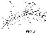
- Fig. 2 shows another embodiment of a negative pressure therapy device 200 in which the device 200 is configured to be re-evacuated or recharged.
- the device 200 comprises an integrated contact layer 230, sealant layer 210 and collection chamber 220.
- the contact layer 230 may be placed in contact with the surface of the skin trauma and a seal may be formed between the skin surrounding the skin trauma using the sealant layer 210.
- the collection chamber 220 may be integrated with the sealant layer 210 and is in fluid communication with the contact layer and the enclosed surgical site through a series of openings 250 in the collection chamber 220 and the contact layer 230, but in other examples, the collection chamber and the sealant layer may be separated components that may be attached using adhesive or mechanical mechanisms.
- the alignment of the collection chamber openings and the sealant layer openings may be facilitated by configuring either the collection chamber openings and/or the sealant layer openings with complementary interfit designs.
- the base sealant layer may lack pre-formed openings, but the collection chamber openings may comprise sharpened or penetrating structures to permit formation of sealant layer openings when the two components are coupled together.
- the collection chamber 220 may be in a pre-evacuated state wherein a level of reduced pressure is already present inside.
- the collection chamber 220 can be at atmospheric pressure when placed on the patient, and a reduced level of pressure can be created in the collection chamber using an external evacuator device 270, such as a durable medical equipment evacuator.
- the external evacuator device 270 may be positioned in an opening 276 of an evacuator fitting 278 on the collection chamber 220.
- the evacuator fitting 276 is in fluid communication with the collection chamber 220.
- the evacuator fitting 276 may be configured as a one-way flow valve that allows air molecules or other materials to be removed from the collection chamber 220 while resisting entry of air molecules or other materials into the collection chamber.
- the collection chamber 220 comprises flexion regions 228 with ribbing, but in other examples, a substantial length of the collection chamber comprises a flexible material.
- Fig. 2 also depicts a collection chamber 220 with one end 222 occluded with an end plug 224.
- the other end 222' of the collection chamber may be fitted with a one-way flow valve 260.
- the device 200 may comprise a separate one-way flow valve 260 for facilitating the emptying of the collection chamber 220 when the collection chamber 220 is filled with exudate or other matter.
- the collection chamber can then be re-evacuated using an external evacuator 270 introduced through the opening 276 of the evacuator fitting 278.
- the one-way flow valve 260 and the means for evacuating the collection chamber 220 are the same structure.
- the one-way flow valve and the means for evacuating the collection chamber are two different structures, as shown in Fig. 2.
- Fig. 2 also shows a device 200 with a moldable collection chamber 220.
- the negative pressure therapy device 300 may comprise a multi-chamber collection system 370, comprising a first chamber 372 and a second chamber 373.
- the multiple chambers may be connected, or may be separate.
- the first and second chambers 372 and 373 may be in fluid communication with each other at an interconnecting opening 374.
- the first chamber 373 of the dual chamber collection chamber 370 has a series of openings 350 that configured to provide fluid communication with the contact layer 330 of the device 300.
- the second chamber 372 of the dual chamber collection chamber 370 can be fitted with a reciprocating mechanism for regulating pressure.
- the second chamber the reciprocating mechanism is shown as a spring 374 attached to a spring housing 378 on the end of the dual chamber collection chamber 370 opposite to the sealed end with end plug 324.
- the spring creates a moving seal 376 through the use of a plunger like apparatus.
- the moving seal 376 self-regulates changes in pressure in the dual chamber collection chamber 370 and moves in response to these changes.
- Fig. 4 illustrates another embodiment of a negative pressure therapy device 400, in which contact layer 430, the collection chamber 420, and the sealant layer 410 of the device are not integrated and the sealant layer 410 is placed above or over the collection chamber 420 and contact layer 430.
- the contact layer 430 is placed in contact with the surgically closed area of skin trauma.
- a moldable collection chamber 420 with ribbing 428 to may be used to manipulate configuration of the chamber 420 for contact and coverage with the contact layer 430.
- a series of openings 450 located in the collection chamber 420 provides for fluid communication between the contact layer 430 and the collection chamber 420.
- the collection chamber 420 once in contact with the contact layer 430, may then be evacuated through the use of suction apparatus 440.
- the suction apparatus can be a syringe, a powered pump, or a forced expansion device.
- the suction apparatus 440 is preferably in fluid communication with the collection chamber 420 through a one-way valve 460. After the collection chamber 420 is evacuated, a sealant layer 410 can then be placed over the collection chamber 420 and the contact layer 430 to form a sealed enclosure with the wound.
- Fig. 5 depicts another embodiment of a device 500, in which the collection chamber 520 comprises corrugated tubing segments 582 with discrete collection members 580 interspersed throughout the collection chamber 520.
- the collection chamber 520 comprises corrugated tubing segments 582 with discrete collection members 580 interspersed throughout the collection chamber 520.
- One end 522 of the corrugated tubing is sealed with an end plug 524 or other closed configuration.
- the other end 522' of the device 500 may be coupled or integral with a suction source 540, such as a constant force spring, a powered suction pump, a durable medical equipment evacuator, or any suitable suction source.
- the contact layer 530 of the device 500 is integrated with the sealant layer 510 and the collection chamber 520 in Fig. 5 . Once placed on the patient, the corrugated tubing segments 582 allow the collection chamber to conform to the surface topology of the patient.
- the device allows the device to move with the patient.
- the corrugated tubing segments allows for significant expansion and compression of the underlying skin.
- the discrete collection member 580 are in preferably fluid communication with the contact layer 530 and skin trauma surface through a series of discrete openings 550.
- an elongate reduced pressure therapy system may be applied along the length of an elongate wound with wound edges that may be approximated.
- the elongate reduced pressure therapy system may also be used with incisions already closed by sutures, staples or adhesives, for example.
- the use of a reduced pressure therapy system on a closed incision may provide more uniform force distribution along an incision, by exerting additional closure forces against tissues not immediately contacting a suture or staple, for example.
- a negative pressure therapy system in some instances, may also resist separation of the wound edges. In some instances, the negative pressure therapy system may resist stretching of the newly formed connective tissue, which may reduce the extent of scarring.
- the wound treatment system may comprise a negative pressure system that is configured to provide both mechanical tension reduction and reduced pressure effects on the incision or wound.
- the reduced pressure effects may or may not include the displacement of the wound edges toward each other by reducing the pressure of the space between the wound edges and/or from pushing or pulling by the sealant layer as the sealant layer is contracted around the support.
- a reduced pressure therapy system may also comprise an elastic sealing layer or a sealing layer configured with one or more elastic members.
- the sealant layer may be attached or adhered to one side of the incision or wound and then stretched and attached to the other side of the incision or wound. Once in place and with the stretching force relieved, the sealant layer or its elastic member may exert opposing forces on each side of the wound to augment the edge approximation and draw the incision or wound edges together.
- the elastic members may be oriented in a transverse position to the longitudinal orientation of the incision or wound, but in other examples, the elastic member may be oriented in multiple directions.
- the sealant layer or the elastic member may comprise a material such as silicone rubber, polyisoprene or other elastomeric material which possesses a sufficient restoring force to pull tissue together when adhered to opposing incision or wound edges in a stretched configuration.
- one or more elastic members may be applied or attached to the sealant layer after the sealant layer has been applied to the incision site or wound site.
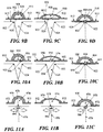
- Figs. 6A to 6C depict another example of a wound treatment device 600 comprising a sealant layer 602 and an elongate support 604.
- the elongate support 604 may be configured with an elongate central channel 606 that may be placed along or over an incision or elongate wound.
- the device 600 may comprise multiple channels in direct communication with the elongate wound.
- the elongate central channel 606 has an open channel configuration that is exposed to the incision or wound along a portion if not all of its longitudinal length, but in other examples, the elongate channel 606 may have a generally closed configuration with a plurality of longitudinally arranged openings along a segment of the channel or the entire channel.
- An open channel or a plurality of longitudinally arranged openings may permit the application of reduced pressure along a length of the wound while possibly reducing the risk that clogging or transient opposition of tissue surfaces may affect the distribution of pressure reduction and/or fluid suction.
- the channel, or the segment of the channel in communication with the incision or wound may have a length of at least about 1 cm or more, 3 cm or more, sometimes about 10 cm or more, and other times about 20 or about 50 cm or more.
- the device 600 may comprise a length of about 70 cm, 100 cm or even 150 cm, which may be cut or shortened to a smaller length.
- the support 604 and/or sealant layer 602 may be provided in the form of a roll or a folded form, which is then dispensed and cut as needed.
- the device 600 (or other devices described herein) may be used to treat any of variety of incisions or wounds, but in some specific examples may be used to a variety of elongate incisions or wound, including but not limited to linear or curvilinear incisions or wounds.
- wounds may include but are not limited to any of a variety of traumatic lacerations or cuts, stemotomy incisions, laparotomy incisions, perineal prostatectomy incisions, vein harvesting incisions, C-section incisions, and the like.
- the elongate central channel 606 may be positioned along an incision or elongate wound and then secured or sealed by placing the sealant layer 602 over the incision and support 604.
- the sealant layer 602 and the support 604 may be integrally formed or pre-attached to each other, such that the sealant layer 602 and the support 604 may be applied to an incision or wound in a single step.
- the sealant layer 602 may have a size and configuration to permit complete sealing of the entire perimeter of the incision and the support 604, but in other examples, one or more accessory seals 608 and 610 may be used.
- the sealant layer 602 may comprise an adhesive on one or more surfaces. In Fig.
- adhesive may be provided along the lateral regions the undersurface of the sealant layer 602, leaving a strip or middle section of the sealant layer 602 free of adhesives.
- end seals 608 and 610 may be used to facilitate sealing about the ends 612 and 614 of the sealant layer 602, but in other embodiments, accessory seals may be used anywhere to provide additional sealing.
- the sealant layer, support, and/or one or more accessory seals may be pre-configured with a connector or port which may be used to coupled the device 600 to a reduced pressure source.
- one of the end seals 610 is preconfigured with a connector 616 that may be used to attach a suction device 618 using an optional connector tube 620.
- the suction source or a connector tube may be configured to pierce and form an aperture through the sealant layer or accessory seal.
- the suction device 618 may be integrally formed with the end seal, sealant layer and/or support 604.
- the support 604 may optionally comprise one or more side flanges or flaps 622 to one or both sides of the elongate channel 606.
- Each of the side flaps 622 may have a width (or dimension transverse to its longest dimension) in the range of about 2 mm to about 50 mm or more, sometimes about 10 mm to about 40 mm, and other times about 20 mm to about 30 mm.
- the side flaps may have an average thickness in the range of about 0.5 mm to about 5 mm or more, sometimes about 0.75 mm to about 3 mm, and other times about 1 mm to about 2 mm.
- the thickness of the side flap may or may not be uniform, and in some examples, the thickness may taper or reduce in a central to peripheral direction, or vice versa.
- the side flaps 622 may comprise the same or different material as the material about the elongate channel 606.
- the support 604 and/or the side flaps 622 may be rigid, semi-rigid or flexible, and may comprise silicone, urethane, or the like, and may or may not comprise a coating.
- one or more sections of the support 604 may comprise an ant-infective coating, including but not limited to a silver alloy or chlorhexidine coating.
- the side flaps 622 may or may not comprise an adhesive on its tissue contacting surface 624 and/or its sealant layer contacting surface 626.
- the support 604 may further comprise a cap structure 628.
- the cap structure 628 may be located on the upper surface of the elongate channel 606 and may be configured to project to one or both sides of the elongate channel 606.
- the cap structure 628 may project anywhere from about 0 mm to about 15 mm or more, sometimes up to about 5 mm, and other times up to about 10 mm.
- one or more elongate side channels 630 may be formed between the cap structure 628 and the side flanges or flaps 622.
- the cap structure 628 may comprise rounded edges or surfaces, which may or may not reduce the risk of puncturing or damaging the sealant layer when contracted onto the support 604.
- an accessory seal, or a sealant layer configured with regions of greater thickness, puncture resistance, or other reinforcement may be positioned about the support 604.
- the side flaps 622 and/or the cap structure 628 may or may not have a symmetrical configuration and/or size with respect to the elongate channel 606.
- one or more openings may be provided in the walls 632 between the central channel 606 and the side channel(s) 630, but in other configurations, communication between the central channel 606 and the side channel(s) 630 may only occur about the ends of the support 604 where the sealant layer 602 may provide a common space or pocket where it may not be adhered to the skin.
- the sealant layer 602 may collapse around or into the support 604.
- sections of the sealant layer 602 may be pulled or pushed into the elongate side channels 630.
- the support 604 may comprise any of a variety of indentations, openings, grooves, channels which may permit contraction of the sealant layer 602 to the support 604, either with suction or by mechanical structures such as a clamp or pushrod, drawstring or any other complementary structure that may be attached or coupled to tighten the sealant layer 602 to the support 604.
- this contraction of the sealant layer 602 may or may not draw the wound edges 634 closer together.
- the application of reduced pressure may also reduce the size or eliminate the gap 636 between the wound edges 634.
- the wound treatment system may also comprise one or more elastic elements incorporated or attachable to the sealant layer.
- elastic bands or threads may be provided in the sealant layer in addition to the elastic properties of the support, if any.
- the elastic bands or threads may have a uniform orientation, but in other configurations, the elastic bands may be oriented in multiple directions.
- the support may also comprise an elastic material or structure (e.g. a spring) which may be configured to further mechanically bias the wound tissue or edges in a particular direction.
- the spring may comprise an attachable clip, which is optionally used with the support to provide additional force with elastic supports, or the contracting force with rigid supports.
- the reduce pressure wound therapy system may be used to treat incisions or elongate wounds that may be longer than the length of the device that is available.
- multiple devices, supports and sealant layers may be arranged in an independent or an overlapping configuration to treat larger wounds.
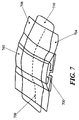
- Fig. 7 for example, two separate supports 700 and 702 and sealant layers 704 and 706 are positioned end-to-end and the junction region 708 is covered with a third sealant layer 710.
- Use of a third sealant layer 710 may be useful, for example, where the support and sealant layer are supplied or manufactured in an integral or pre-attached configuration.
- the ends of the supports 700 and 702 and the sealant layer 704 and 706 are depicted as touching at the junction region 708, in other examples, partial or full gaps may be provided between supports and/or sealant layers.
- the supports and/or sealant layers may also be arranged in a parallel fashion.
- a third sealant layer need not be used, as one sealant layer may be overlapped over another where the sealant layer extends past the end of it associated support.
- multiple sealant layers or supports may be provided and used with a lesser number of supports or sealant layers, respectively.
- more than one suction device may be used with longer or larger support or sealant layers.
- a support 800 comprise two elongate support segments 802 and 804 which are configured to be generally joined along their longitudinal lengths at a coupling interface 806.
- a support 800 comprising separate longitudinal segments 802 and 804 may be used to separately attach each segment 802 and 804 to one edge of an incision or wound (e.g. by adhesives or suturing) and are then joined together to approximate the wound edges.
- separate joinable components may be easier to attach to the skin than a unibody support.
- the longitudinal segments 802 and 804 may be rigid, semi-rigid or flexible, and although the segments 802 and 804 are depicted as each contributing about 50% of the structure, e.g. generally symmetrically split except for possibly the coupling interface. In other examples, however, the longitudinal segments may be asymmetrically split.
- the coupling interface 806 depicted in Fig. 8 comprises a complementary set of grooves 808 and ridges 810 located along the longitudinal inner surface 812 of each segment 802 and 804, but any of a variety of coupling interfaces 806 may be used, including other snapfits.
- locking interfaces, mechanisms or structures may include but are not limited to resealable adhesive layers, slide locks, hinge clamps, clips, locking pins with lockable lumens, zippers, elastic binding bands, and the like.
- structures that may be used to contract the sealant layer into a unibody support may also be used to contract the sealant layer into a multi-segment support and/or to couple the segments of a multi-segment support together.
- Fig. 9A depicts one example of a negative pressure therapy system 900 comprising an elastic support 902 and an optional suction system 904.
- An optional contact layer 906 may be provided under the elastic support 902.
- the elastic support 902 is configured with one or more longitudinal conduits 908 or channels.
- the conduit or channel may be fully enclosed or may be at least partially open.
- the conduit 908 in Fig. 9 has a closed configuration with a plurality of apertures 910 to permit air or fluid communication with the underlying wound or incision.
- the lateral flaps 912 of the elastic support 904 may comprise an adhesive, which may be used to at least seal a portion of the conduit 908 and the external space, if any, between the incision or wound and the apertures 910.
- the lateral flaps 912 may extend to one or both ends of the support, but in the example, depicted in Fig. 9A , end seals 914 and/or 916 may be used to facilitate sealing about the ends 918 and 920 of the support 902.
- at least one of the end seals 916 may be provided with a connector 922 for attachment of the suction system 904, but in other embodiments, the connector may be located on the elastic support 902.
- a large sealant layer may be used to cover a larger portion if not all of the support, and with or without a protective layer.
- some embodiments of the elastic support may comprise segmented non-sealing lateral flaps which are configured to elastically bring wound edges together. The segmentation may facilitate the application of the elastic support in a sectional manner, but may or may not provide sealing ability, such that a sealant layer applied over the elastic support may be used to provide a sealed space about the support.
- the flaps 912 of the elastic support 902 may be elastically stretched or pulled away from each other and applied in its stretched state to the incision or wound such that each flap 912 is adhered to the skin surface 922 to a respective edge of the incision or wound.
- the support 902 may be sufficient stiff or rigid such that a substantial longitudinal length of the flaps 912 can be stretched, but in other configurations, a smaller portion of the flaps 912 may be pulled away, which may facilitate the application of the support to non-linear incisions or wound by permitting adherence or attachment of the support section-by-section.
- Fig. 9 depicts how two elastic supports 902 with flaps 912 may be positioned serially or in an end-to-end fashion to treat incisions or wounds having a longer length by covering the junction 958 with an accessory seal 960. As noted previously, although the ends of the supports 902 and their flaps 912 are depicted as touching at the junction region 958, in other examples, partial or full gaps may be provided between supports and/or their flaps.
- the elastic support may comprise any of a variety of configurations. As depicted in Figs. 9B to 9D . the elastic support 902 may comprise an elastomeric member 926 which may augment the elastomeric properties, if any, of the flaps 912 and/or wall 928 of the conduit 908. As further illustrated, the apertures 910 of the elastic support 902 may be provided directly in the elastomeric member 926, and in some configurations the apertures 910 may also deform in shape when force is applied to the flaps 912.
- Fig. 10A to 10C depicts another embodiment of an elastic support 950 with flaps 952, wherein the apertures 954 are provided in a non-elastic structure 956.
- the non-elastic structure 956 may have any of a variety of configurations, including rings or frames, and may form either a partial or a complete perimeter of the aperture 954.
- the non-elastic structures 956 may be separate for each aperture 954 or they may be interconnected.
- Fig. 11A to 11C depicts still another embodiment of an elastic support 970 with flaps 972 comprises an elastic material such that a specific elastomeric member is not used.
- the elastic support 970 comprise an open channel 974 that lacks discrete apertures and instead is generally open along the length of the channel 974 to the edges 922 and space 924 of the underlying incision or wound.
- the elastic support 970 may be applied to an incision 976 closed with sutures 978 or other type of incision closure such as staples.
- the sutures 978 may any type of suture and may be used with any of a variety of suture techniques, including running sutures and interrupted sutures. In some variations, although the sutures 978 may generally maintain the approximation of the wound edges 980, separation forces acting at the sutures 978 may generate focal regions of tissue tension.
- Application of the elastic support 970 to the incision may be used to apply additional contiguous force along a substantial length of the incision 976, which may or may not reduce the focal tissue tension and possibly improve incision healing.
- the devices described herein may also be used to treat non-elongate incisions or wounds.
- Figs. 12 to 15 depict various examples of using an elongate negative pressure therapy system to treat non-elongate wounds.
- an elongate negative pressure therapy device 1000 and a sealant layer 1002 are positioned around the perimeter of wound 1004.
- the device 1000 may comprise apertures 1006, 1008 and 1010 of varying size.
- smaller apertures 1004 may be used at distances closer to the suction source or interface 1012, while larger apertures 1008 may be used at relatively farther distances.
- the size of the apertures may be uniform, but either the number and/or the spacing of the apertures may vary along the longitudinal length of the device.
- Fig. 13 depicts another example of a negative pressure therapy device 1020 arranged in a spiral orientation with respect to a wound 1022.
- the spiral orientation may augment the pressure or suction about the center of the wound 1022, compared to the device arranged depicted in Fig. 12 .
- Fig. 14 is still another example of a device 1030 comprising alternating rigid sections 1032 and flexion sections 1034 arranged in a back-and-forth or zig-zag orientation along a non-elongate wound 1036.
- the rigid sections 1032 may also rotate with respect to the flexion section 1034 or other articulation of the device.
- the device need not be fully located within the borders of the wound 1036, and although all of the device apertures 1038 are located within the wound borders, in other examples one or more apertures may be located outside the border of the wound.
- Fig. 15 depicts another example where multiple devices 1040 and sealant layers 1042 are used to close a non-linear surgical incision.
- the surgical incision comprising a T-incision with a transverse incision 1044 and a midline incision 1046, and is treated using two open-channel devices 1040 applied to each incision 1044 and 1046, with overlapping sealant layers 1042.
- more than two devices and two sealant layers may be used, e.g. one longer device may be used along the entire length of the midline incision 1046 and two smaller devices may be used along each remaining segment of the transverse incision 1044.
- open channel devices 1040 may be used when surgical close is performed with staples 1048 or any other protruding closure component.
Priority Applications (1)
| Application Number | Priority Date | Filing Date | Title |
|---|---|---|---|
| EP19194314.1A EP3590480B1 (fr) | 2007-10-11 | 2008-10-10 | Dispositif de traitement de plaies par pression négative à incision fermée |
Applications Claiming Priority (3)
| Application Number | Priority Date | Filing Date | Title |
|---|---|---|---|
| US97931507P | 2007-10-11 | 2007-10-11 | |
| EP08836852.7A EP2203137B1 (fr) | 2007-10-11 | 2008-10-10 | Dispositif de traitement de plaie par application d'une pression négative sur une incision fermée |
| PCT/US2008/079613 WO2009049232A1 (fr) | 2007-10-11 | 2008-10-10 | Dispositif de traitement de plaie par application d'une pression négative sur une incision fermée et procédés d'utilisation |
Related Parent Applications (1)
| Application Number | Title | Priority Date | Filing Date |
|---|---|---|---|
| EP08836852.7A Division EP2203137B1 (fr) | 2007-10-11 | 2008-10-10 | Dispositif de traitement de plaie par application d'une pression négative sur une incision fermée |
Related Child Applications (2)
| Application Number | Title | Priority Date | Filing Date |
|---|---|---|---|
| EP19194314.1A Division EP3590480B1 (fr) | 2007-10-11 | 2008-10-10 | Dispositif de traitement de plaies par pression négative à incision fermée |
| EP19194314.1A Division-Into EP3590480B1 (fr) | 2007-10-11 | 2008-10-10 | Dispositif de traitement de plaies par pression négative à incision fermée |
Publications (2)
| Publication Number | Publication Date |
|---|---|
| EP3053554A1 true EP3053554A1 (fr) | 2016-08-10 |
| EP3053554B1 EP3053554B1 (fr) | 2019-12-11 |
Family
ID=40549608
Family Applications (3)
| Application Number | Title | Priority Date | Filing Date |
|---|---|---|---|
| EP19194314.1A Active EP3590480B1 (fr) | 2007-10-11 | 2008-10-10 | Dispositif de traitement de plaies par pression négative à incision fermée |
| EP08836852.7A Revoked EP2203137B1 (fr) | 2007-10-11 | 2008-10-10 | Dispositif de traitement de plaie par application d'une pression négative sur une incision fermée |
| EP16156890.2A Active EP3053554B1 (fr) | 2007-10-11 | 2008-10-10 | Dispositif de traitement de plaies par pression négative à incision fermée |
Family Applications Before (2)
| Application Number | Title | Priority Date | Filing Date |
|---|---|---|---|
| EP19194314.1A Active EP3590480B1 (fr) | 2007-10-11 | 2008-10-10 | Dispositif de traitement de plaies par pression négative à incision fermée |
| EP08836852.7A Revoked EP2203137B1 (fr) | 2007-10-11 | 2008-10-10 | Dispositif de traitement de plaie par application d'une pression négative sur une incision fermée |
Country Status (6)
| Country | Link |
|---|---|
| US (7) | US8246590B2 (fr) |
| EP (3) | EP3590480B1 (fr) |
| JP (1) | JP5511670B2 (fr) |
| AU (1) | AU2008310622B2 (fr) |
| CA (1) | CA2702338C (fr) |
| WO (1) | WO2009049232A1 (fr) |
Families Citing this family (150)
| Publication number | Priority date | Publication date | Assignee | Title |
|---|---|---|---|---|
| GB0224986D0 (en) | 2002-10-28 | 2002-12-04 | Smith & Nephew | Apparatus |
| GB0325129D0 (en) | 2003-10-28 | 2003-12-03 | Smith & Nephew | Apparatus in situ |
| AU2004293815B2 (en) | 2003-11-20 | 2010-07-22 | The Henry M. Jackson Foundation For The Advancement Of Military Medicine, Inc. | Portable hand pump for evacuation of fluids |
| US8062272B2 (en) | 2004-05-21 | 2011-11-22 | Bluesky Medical Group Incorporated | Flexible reduced pressure treatment appliance |
| US7708724B2 (en) * | 2004-04-05 | 2010-05-04 | Blue Sky Medical Group Incorporated | Reduced pressure wound cupping treatment system |
| US7909805B2 (en) | 2004-04-05 | 2011-03-22 | Bluesky Medical Group Incorporated | Flexible reduced pressure treatment appliance |
| US7776028B2 (en) | 2004-04-05 | 2010-08-17 | Bluesky Medical Group Incorporated | Adjustable overlay reduced pressure wound treatment system |
| US10058642B2 (en) | 2004-04-05 | 2018-08-28 | Bluesky Medical Group Incorporated | Reduced pressure treatment system |
| US8337475B2 (en) | 2004-10-12 | 2012-12-25 | C. R. Bard, Inc. | Corporeal drainage system |
| EP1922045B1 (fr) | 2005-09-07 | 2012-11-07 | Tyco Healthcare Group LP | Pansement pour plaies autonome muni d'une micropompe |
| US7779625B2 (en) | 2006-05-11 | 2010-08-24 | Kalypto Medical, Inc. | Device and method for wound therapy |
| CA2702338C (fr) * | 2007-10-11 | 2016-11-08 | Spiracur, Inc. | Dispositif de traitement de plaie par application d'une pression negative sur une incision fermee et procedes d'utilisation |
| CA2705896C (fr) | 2007-11-21 | 2019-01-08 | Smith & Nephew Plc | Pansement de plaie |
| GB0722820D0 (en) | 2007-11-21 | 2008-01-02 | Smith & Nephew | Vacuum assisted wound dressing |
| HUE043133T2 (hu) | 2007-11-21 | 2019-07-29 | Smith & Nephew | Sebkötözés |
| US9033942B2 (en) | 2008-03-07 | 2015-05-19 | Smith & Nephew, Inc. | Wound dressing port and associated wound dressing |
| GB0804654D0 (en) * | 2008-03-13 | 2008-04-16 | Smith & Nephew | Vacuum closure device |
| GB0808376D0 (en) | 2008-05-08 | 2008-06-18 | Bristol Myers Squibb Co | Wound dressing |
| EP2319550B1 (fr) † | 2008-05-30 | 2016-04-20 | KCI Licensing, Inc. | Structures de pansement pour le traitement de blessures utilisant une pression réduite |
| GB0817796D0 (en) | 2008-09-29 | 2008-11-05 | Convatec Inc | wound dressing |
| WO2010053870A1 (fr) | 2008-11-07 | 2010-05-14 | Kci Licensing, Inc. | Pansement et systèmes de traitement de plaies à pression réduite |
| GB0900423D0 (en) | 2009-01-12 | 2009-02-11 | Smith & Nephew | Negative pressure device |
| US8444614B2 (en) * | 2009-04-10 | 2013-05-21 | Spiracur, Inc. | Methods and devices for applying closed incision negative pressure wound therapy |
| WO2010118316A1 (fr) * | 2009-04-10 | 2010-10-14 | Spiracur, Inc. | Procédés et dispositifs pour l'application d'un traitement par pression négative sur des plaies d'incision fermées |
| US8663198B2 (en) | 2009-04-17 | 2014-03-04 | Kalypto Medical, Inc. | Negative pressure wound therapy device |
| US20100324516A1 (en) | 2009-06-18 | 2010-12-23 | Tyco Healthcare Group Lp | Apparatus for Vacuum Bridging and/or Exudate Collection |
| US10159825B2 (en) | 2009-09-17 | 2018-12-25 | Zipline Medical, Inc. | Rapid closing surgical closure device |
| CN102811671B (zh) | 2009-09-17 | 2016-08-03 | 锡普莱恩医疗有限公司 | 快速闭合用外科闭合装置 |
| EP3520830B1 (fr) | 2009-12-22 | 2023-10-18 | Smith & Nephew, Inc. | Appareils pour le traitement de plaies par pression négative |
| DE102009060596A1 (de) * | 2009-12-23 | 2011-06-30 | Paul Hartmann Aktiengesellschaft, 89522 | Anschlussvorrichtung zur Verwendung bei der Unterdruckbehandlung von Wunden |
| US9061095B2 (en) | 2010-04-27 | 2015-06-23 | Smith & Nephew Plc | Wound dressing and method of use |
| US8623047B2 (en) | 2010-04-30 | 2014-01-07 | Kci Licensing, Inc. | System and method for sealing an incisional wound |
| USRE48117E1 (en) | 2010-05-07 | 2020-07-28 | Smith & Nephew, Inc. | Apparatuses and methods for negative pressure wound therapy |
| CN103002844B (zh) | 2010-06-14 | 2016-08-31 | 奇普林医药公司 | 用于抑制疤痕形成的方法和装置 |
| JP4790091B1 (ja) * | 2010-07-29 | 2011-10-12 | 有限会社ちょうりゅう | 創離開防止用補助具 |
| US11291760B2 (en) * | 2010-08-10 | 2022-04-05 | Kci Licensing, Inc. | Controlled negative pressure apparatus and alarm mechanism |
| US8753322B2 (en) * | 2010-08-10 | 2014-06-17 | Spiracur Inc. | Controlled negative pressure apparatus and alarm mechanism |
| US8795246B2 (en) * | 2010-08-10 | 2014-08-05 | Spiracur Inc. | Alarm system |
| GB201020236D0 (en) | 2010-11-30 | 2011-01-12 | Convatec Technologies Inc | A composition for detecting biofilms on viable tissues |
| JP5965409B2 (ja) | 2010-12-08 | 2016-08-03 | コンバテック・テクノロジーズ・インコーポレイテッドConvatec Technologies Inc | 創傷滲出液を評価するための統合システム |
| JP6151186B2 (ja) | 2010-12-08 | 2017-06-21 | コンバテック・テクノロジーズ・インコーポレイテッドConvatec Technologies Inc | 創傷滲出液システム付属装置 |
| USD714433S1 (en) | 2010-12-22 | 2014-09-30 | Smith & Nephew, Inc. | Suction adapter |
| CA2821681C (fr) | 2010-12-22 | 2023-05-16 | Smith & Nephew, Inc. | Appareils et procedes pour therapie de plaie a pression negative |
| EP2654641B1 (fr) * | 2010-12-23 | 2016-12-14 | Alfons Erdmann | Élément couvrant comportant un corps manchon |
| WO2012106590A2 (fr) | 2011-02-04 | 2012-08-09 | University Of Massachusetts | Dispositif de fermeture de plaie par pression négative |
| US9421132B2 (en) | 2011-02-04 | 2016-08-23 | University Of Massachusetts | Negative pressure wound closure device |
| CN106725645A (zh) * | 2011-03-31 | 2017-05-31 | 佛尔蒙特·伊夫斯 | 调整力的组织间桥 |
| US9058634B2 (en) | 2011-05-24 | 2015-06-16 | Kalypto Medical, Inc. | Method for providing a negative pressure wound therapy pump device |
| EP2714116A4 (fr) | 2011-05-24 | 2015-01-07 | Kalypto Medical Inc | Dispositif constitué de modules de commande et de pompe, permettant d'obtenir une pression négative pour le traitement de plaies |
| ITBO20110296A1 (it) * | 2011-05-24 | 2012-11-25 | Met S R L | Dispositivo a pressione negativa per la cura delle ferite |
| US9067003B2 (en) | 2011-05-26 | 2015-06-30 | Kalypto Medical, Inc. | Method for providing negative pressure to a negative pressure wound therapy bandage |
| JP5095846B1 (ja) * | 2011-07-07 | 2012-12-12 | 有限会社ちょうりゅう | 処置対応型創離開防止用補助具 |
| GB201115182D0 (en) | 2011-09-02 | 2011-10-19 | Trio Healthcare Ltd | Skin contact material |
| AU2012325922B2 (en) | 2011-10-20 | 2017-06-01 | Brijjit Medical, Inc. | Removable covering and interactive packaging |
| US9561034B2 (en) | 2011-11-01 | 2017-02-07 | Zipline Medical, Inc. | Surgical incision and closure apparatus |
| US10123801B2 (en) | 2011-11-01 | 2018-11-13 | Zipline Medical, Inc. | Means to prevent wound dressings from adhering to closure device |
| US9050086B2 (en) | 2011-11-01 | 2015-06-09 | Zipline Medical, Inc. | Surgical incision and closure apparatus |
| US10123800B2 (en) | 2011-11-01 | 2018-11-13 | Zipline Medical, Inc. | Surgical incision and closure apparatus with integrated force distribution |
| GB2497406A (en) | 2011-11-29 | 2013-06-12 | Webtec Converting Llc | Dressing with a perforated binder layer |
| GB201120693D0 (en) | 2011-12-01 | 2012-01-11 | Convatec Technologies Inc | Wound dressing for use in vacuum therapy |
| EP3708196A1 (fr) | 2012-03-12 | 2020-09-16 | Smith & Nephew PLC | Appareil à pression réduite et procédés |
| US9295742B2 (en) | 2012-04-16 | 2016-03-29 | Puracath Medical, Inc. | System and method for disinfecting a catheter system |
| CA2874396A1 (fr) * | 2012-05-22 | 2014-01-23 | Smith & Nephew Plc | Dispositif de fermeture de blessure |
| CN104661601B (zh) | 2012-05-22 | 2018-06-22 | 史密夫及内修公开有限公司 | 用于伤口治疗的设备和方法 |
| WO2013175309A1 (fr) | 2012-05-24 | 2013-11-28 | Smith & Nephew Plc | Dispositifs et procédés pour traiter et fermer des plaies avec une pression négative |
| MX369689B (es) | 2012-07-16 | 2019-11-19 | Smith & Nephew Inc | Dispositivo de cierre de herida de presión negativa. |
| WO2014044400A1 (fr) * | 2012-09-20 | 2014-03-27 | Lohmann & Rauscher Gmbh | Dispositif de traitement par pression négative et feuille pour la réalisation d'un dispositif de traitement par pression négative |
| JP5922008B2 (ja) | 2012-11-30 | 2016-05-24 | 富士フイルム株式会社 | 転写フィルムおよび透明積層体、それらの製造方法、静電容量型入力装置ならびに画像表示装置 |
| BR112015014816A2 (pt) | 2012-12-20 | 2017-07-11 | Convatec Technologies Inc | processamento de fibras celulósicas modificadas quimicamente |
| WO2014120620A1 (fr) | 2013-01-29 | 2014-08-07 | Puracath Medical, Inc. | Appareil et procédé pour désinfecter un cathéter |
| WO2014165275A1 (fr) | 2013-03-13 | 2014-10-09 | Smith & Nephew Inc. | Dispositif de fermeture de plaie par pression négative et systèmes et procédés d'utilisation lors du traitement des plaies par pression négative |
| WO2014140578A1 (fr) | 2013-03-14 | 2014-09-18 | Smith & Nephew Plc | Produits compressibles de remplissage de plaies, et systèmes et procédés d'utilisation pour traiter des plaies à l'aide d'une pression négative |
| EP3021806B1 (fr) | 2013-07-16 | 2018-01-31 | Smith & Nephew PLC | Appareil pour le traitement des plaies |
| WO2015012887A1 (fr) * | 2013-07-24 | 2015-01-29 | Zipline Medical, Inc. | Appareil d'incision et de fermeture chirurgicale |
| US10660992B2 (en) | 2013-10-21 | 2020-05-26 | Smith & Nephew, Inc. | Negative pressure wound closure device |
| WO2015103556A1 (fr) | 2014-01-05 | 2015-07-09 | Zipline Medical, Inc. | Dispositif de fermeture de plaie à instrument |
| RU2016133735A (ru) | 2014-01-21 | 2018-02-28 | СМИТ ЭНД НЕФЬЮ ПиЭлСи | Сжимаемая повязка для лечения раны отрицательным давлением |
| CN106456376B (zh) | 2014-01-21 | 2020-12-15 | 史密夫及内修公开有限公司 | 伤口治疗设备 |
| US11007361B2 (en) | 2014-06-05 | 2021-05-18 | Puracath Medical, Inc. | Transfer catheter for ultraviolet disinfection |
| EP3177333A4 (fr) * | 2014-08-08 | 2018-04-04 | Innovation Technologies, Inc. | Matériaux et procédés pour lutter contre les infections avec traitement des plaies par pression négative |
| EP3215198B1 (fr) * | 2014-11-03 | 2021-04-28 | Fistula Solution Corporation | Dispositifs de confinement pour le traitement de fistules intestinales et de plaies complexes |
| US11426302B2 (en) | 2014-11-03 | 2022-08-30 | Fistula Solution Corporation | Containment devices for treatment of intestinal fistulas and complex wounds |
| CN108367085A (zh) | 2015-03-18 | 2018-08-03 | 普拉卡斯医疗公司 | 紫外线消毒用导管连接系统 |
| EP3288508B1 (fr) | 2015-04-27 | 2020-01-08 | Smith & Nephew plc | Appareils à pression réduite |
| JP2018519864A (ja) | 2015-04-29 | 2018-07-26 | スミス アンド ネフュー インコーポレイテッド | 陰圧創傷閉鎖デバイス |
| CN108136081A (zh) | 2015-07-29 | 2018-06-08 | 创新疗法公司 | 伤口治疗装置压力监控和控制系统 |
| CN105147344B (zh) * | 2015-10-19 | 2018-12-21 | 张新平 | 皮肤伤口辅助愈合装置 |
| CN105147345B (zh) * | 2015-10-19 | 2019-12-13 | 张新平 | 皮肤伤口负压减张缝合装置 |
| US10575991B2 (en) | 2015-12-15 | 2020-03-03 | University Of Massachusetts | Negative pressure wound closure devices and methods |
| US10814049B2 (en) | 2015-12-15 | 2020-10-27 | University Of Massachusetts | Negative pressure wound closure devices and methods |
| WO2017153357A1 (fr) | 2016-03-07 | 2017-09-14 | Smith & Nephew Plc | Appareils et procédés de traitement de plaies avec une source de pression négative intégrée dans un pansement |
| US20190038473A1 (en) * | 2016-03-18 | 2019-02-07 | Kci Licensing, Inc. | Dressing Augmentation To Promote Epithelialization |
| PL3435941T3 (pl) | 2016-03-30 | 2022-05-09 | Convatec Technologies Inc. | Wykrywanie infekcji drobnoustrojowych w ranach |
| WO2017212345A2 (fr) | 2016-03-30 | 2017-12-14 | Synovo Gmbh | Détection d'une infection microbienne dans les plaies |
| US11285047B2 (en) | 2016-04-26 | 2022-03-29 | Smith & Nephew Plc | Wound dressings and methods of use with integrated negative pressure source having a fluid ingress inhibition component |
| CN109069710B (zh) | 2016-05-03 | 2022-04-12 | 史密夫及内修公开有限公司 | 优化到负压治疗系统中的负压源的功率传输 |
| AU2017259003B2 (en) | 2016-05-03 | 2022-09-22 | Smith & Nephew Plc | Systems and methods for driving negative pressure sources in negative pressure therapy systems |
| WO2017191154A1 (fr) | 2016-05-03 | 2017-11-09 | Smith & Nephew Plc | Activation et commande d'un dispositif de traitement des plaies par pression négative |
| AU2017292876B2 (en) | 2016-07-08 | 2022-01-20 | Convatec Technologies Inc. | Fluid collection apparatus |
| KR20190026858A (ko) | 2016-07-08 | 2019-03-13 | 컨바텍 테크놀러지스 인크 | 가요성 부압 시스템 |
| ES2912094T3 (es) | 2016-07-08 | 2022-05-24 | Convatec Technologies Inc | Detección de flujo de fluidos |
| EP3484559B1 (fr) | 2016-07-18 | 2023-08-23 | Merit Medical Systems, Inc. | Dispositif gonflable de compression d'artères radiales |
| JP7303104B2 (ja) | 2016-08-25 | 2023-07-04 | スミス アンド ネフュー ピーエルシー | 吸収性陰圧創傷療法被覆材 |
| WO2018041805A1 (fr) | 2016-08-30 | 2018-03-08 | Smith & Nephew Plc | Systèmes pour appliquer une thérapie à pression réduite |
| WO2018060144A1 (fr) | 2016-09-27 | 2018-04-05 | Smith & Nephew Plc | Dispositifs de fermeture de plaie à des parties solubles |
| AU2017336310B2 (en) | 2016-09-30 | 2022-12-08 | Smith & Nephew Plc | Negative pressure wound treatment apparatuses and methods with integrated electronics |
| EP4252675A3 (fr) | 2016-10-21 | 2023-11-15 | Brijjit Medical, Inc. | Ponts tissulaires à modulation de force |
| WO2018081795A1 (fr) | 2016-10-31 | 2018-05-03 | Zipline Medical, Inc. | Systèmes et procédés de surveillance d'une thérapie physique du genou et d'autres articulations |
| CN110167495B (zh) | 2016-11-02 | 2022-06-14 | 史密夫和内修有限公司 | 伤口闭合设备 |
| JP2020505985A (ja) * | 2017-01-27 | 2020-02-27 | ケーシーアイ ライセンシング インコーポレイテッド | 滴下機能を備えた多層腹部閉鎖ドレッシング |
| WO2018156730A1 (fr) | 2017-02-22 | 2018-08-30 | Cornell University | Pansement à vide mécanique de gestion, protection et aspiration mécaniques de petites plaies incisionnelles |
| CN110582257B (zh) | 2017-03-08 | 2022-03-15 | 史密夫及内修公开有限公司 | 存在故障条件时的负压伤口治疗装置控制 |
| JP7121050B2 (ja) | 2017-05-09 | 2022-08-17 | スミス アンド ネフュー ピーエルシー | 陰圧創傷療法システムの冗長制御 |
| US11324876B2 (en) | 2017-06-13 | 2022-05-10 | Smith & Nephew Plc | Collapsible structure and method of use |
| WO2018229009A1 (fr) | 2017-06-13 | 2018-12-20 | Smith & Nephew Plc | Dispositif de fermeture de plaie et procédé d'utilisation |
| JP2020523052A (ja) | 2017-06-14 | 2020-08-06 | スミス アンド ネフュー インコーポレイテッド | 創傷治療における創傷閉鎖の流体除去管理および制御 |
| WO2018229011A1 (fr) | 2017-06-14 | 2018-12-20 | Smith & Nephew Plc | Structure pliable pour fermeture de plaie et méthode d'utilisation |
| US11395873B2 (en) | 2017-06-14 | 2022-07-26 | Smith & Nephew, Inc. | Control of wound closure and fluid removal management in wound therapy |
| CN110740715B (zh) | 2017-06-14 | 2022-04-12 | 史密夫及内修公开有限公司 | 用于伤口闭合的可塌缩片材及使用方法 |
| CN107174300B (zh) * | 2017-06-22 | 2023-09-12 | 张新平 | 皮肤伤口负压驱动对平愈合器 |
| CN107174301A (zh) * | 2017-07-04 | 2017-09-19 | 石嘴山市第二人民医院 | 一种创口支撑结构及创口支撑系统 |
| US11607344B2 (en) | 2017-07-27 | 2023-03-21 | Smith & Nephew Plc | Customizable wound closure device and method of use |
| WO2019030136A1 (fr) | 2017-08-07 | 2019-02-14 | Smith & Nephew Plc | Dispositif de fermeture de plaie doté d'une couche protectrice et procédé d'utilisation |
| US11375923B2 (en) | 2017-08-29 | 2022-07-05 | Smith & Nephew Plc | Systems and methods for monitoring wound closure |
| SG11202001900UA (en) | 2017-09-13 | 2020-04-29 | Smith & Nephew | Negative pressure wound treatment apparatuses and methods with integrated electronics |
| GB201718070D0 (en) | 2017-11-01 | 2017-12-13 | Smith & Nephew | Negative pressure wound treatment apparatuses and methods with integrated electronics |
| USD862695S1 (en) | 2017-10-20 | 2019-10-08 | Emrge, Llc | Medical tool for use in applying medical article |
| USD876641S1 (en) | 2017-10-20 | 2020-02-25 | Emrge, Llc. | Medical article for treating a wound and/or scar tissue |
| WO2019086332A1 (fr) | 2017-11-01 | 2019-05-09 | Smith & Nephew Plc | Appareils et procédés de traitement de plaies par pression négative avec électronique intégrée |
| GB201718054D0 (en) | 2017-11-01 | 2017-12-13 | Smith & Nephew | Sterilization of integrated negative pressure wound treatment apparatuses and sterilization methods |
| GB201718072D0 (en) | 2017-11-01 | 2017-12-13 | Smith & Nephew | Negative pressure wound treatment apparatuses and methods with integrated electronics |
| WO2019113275A1 (fr) | 2017-12-06 | 2019-06-13 | Cornell University | Pansement à pression négative actionné manuellement (npwt) équipé d'une pompe plus efficace, d'un indicateur de pression automatique et d'un limiteur de pression automatique |
| US10624794B2 (en) | 2018-02-12 | 2020-04-21 | Healyx Labs, Inc. | Negative pressure wound therapy systems, devices, and methods |
| CN112165961A (zh) | 2018-04-02 | 2021-01-01 | Ic外科公司 | 负压泵及相关方法 |
| CA3100467A1 (fr) * | 2018-05-16 | 2019-11-21 | Midwest Training and Development Services, LLC | Systeme de pose de pansement sur une plaie a pression negative |
| GB201811449D0 (en) | 2018-07-12 | 2018-08-29 | Smith & Nephew | Apparatuses and methods for negative pressure wound therapy |
| GB2574074B (en) | 2018-07-27 | 2020-05-20 | Mclaren Applied Tech Ltd | Time synchronisation |
| USD898925S1 (en) | 2018-09-13 | 2020-10-13 | Smith & Nephew Plc | Medical dressing |
| US11497843B2 (en) | 2018-11-20 | 2022-11-15 | Aatru Medical, LLC | Negative pressure device including expandable segment |
| EP3893825A1 (fr) | 2018-12-13 | 2021-10-20 | University of Massachusetts | Dispositifs et méthodes de fermeture de plaie par pression négative |
| US11207097B2 (en) | 2019-02-13 | 2021-12-28 | Andrew Thomas Obst | Fluid management device for medical tubes and drainage incisions |
| US11523932B2 (en) | 2019-06-26 | 2022-12-13 | Andrew Thomas Obst | Enteric fistula, rectovaginal fistula, and ostomy effluent containment system, and devices and methods thereof |
| US20220370705A1 (en) * | 2019-07-24 | 2022-11-24 | Kci Licensing, Inc. | System For Treating A Tissue Site |
| WO2021072021A1 (fr) | 2019-10-11 | 2021-04-15 | Emrge, Llc | Dispositif médical d'application de force sur du tissu biologique, ou similaire |
| GB2588236B (en) | 2019-10-18 | 2024-03-20 | Mclaren Applied Ltd | Gyroscope bias estimation |
| US11331221B2 (en) | 2019-12-27 | 2022-05-17 | Convatec Limited | Negative pressure wound dressing |
| US11771819B2 (en) | 2019-12-27 | 2023-10-03 | Convatec Limited | Low profile filter devices suitable for use in negative pressure wound therapy systems |
| CN111904813B (zh) * | 2020-07-30 | 2022-04-12 | 上海交通大学医学院附属第九人民医院 | 一种负压抑疤贴片及包含其的负压抑疤组件 |
| USD980434S1 (en) | 2021-01-14 | 2023-03-07 | Emrge, Llc | Medical article for treating a wound and/or scar tissue |
| CN115192216B (zh) * | 2022-09-19 | 2022-11-25 | 吉林大学第一医院 | 一种术后手术切口防崩线护理装置 |
Citations (4)
| Publication number | Priority date | Publication date | Assignee | Title |
|---|---|---|---|---|
| WO2001085248A1 (fr) * | 2000-05-09 | 2001-11-15 | Kci Licensing, Inc. | Pansement abdominal |
| WO2005025447A2 (fr) * | 2003-09-08 | 2005-03-24 | Microlin, L.C. | Dispositif et procede pour soigner des blessures |
| WO2009146441A1 (fr) * | 2008-05-30 | 2009-12-03 | Kci Licensing, Inc. | Pansement et systèmes super absorbants à pression réduite |
| EP2711034A1 (fr) * | 2008-03-05 | 2014-03-26 | KCI Licensing Inc. | Pansement pour appliquer une pression réduite à et recueillir et stocker un fluide à partir d'un site tissulaire |
Family Cites Families (288)
| Publication number | Priority date | Publication date | Assignee | Title |
|---|---|---|---|---|
| US114750A (en) * | 1871-05-16 | Improvement in sticking or adhesive plasters | ||
| US1355846A (en) | 1920-02-06 | 1920-10-19 | David A Rannells | Medical appliance |
| US2012755A (en) * | 1934-07-12 | 1935-08-27 | Muth Otto De | Surgical dressing |
| US2198666A (en) | 1936-09-30 | 1940-04-30 | Lakeland Foundation | Syringe |
| US2472116A (en) | 1945-10-18 | 1949-06-07 | Emma C Maynes | Syringe holder |
| US2531757A (en) | 1947-02-05 | 1950-11-28 | Margaret S Whinery | Bandage |
| US2547758A (en) | 1949-01-05 | 1951-04-03 | Wilmer B Keeling | Instrument for treating the male urethra |
| US2660342A (en) | 1949-04-01 | 1953-11-24 | Ruf Herman | Burette with variable capacity |
| US2632443A (en) | 1949-04-18 | 1953-03-24 | Eleanor P Lesher | Surgical dressing |
| GB692578A (en) | 1949-09-13 | 1953-06-10 | Minnesota Mining & Mfg | Improvements in or relating to drape sheets for surgical use |
| US2682873A (en) | 1952-07-30 | 1954-07-06 | Johnson & Johnson | General purpose protective dressing |
| NL189176B (nl) | 1956-07-13 | 1900-01-01 | Hisamitsu Pharmaceutical Co | Pleister op basis van een synthetische rubber. |
| US2863452A (en) | 1954-06-22 | 1958-12-09 | Ogle Edna | Syringe with adjustable aspirating means |
| US2969057A (en) | 1957-11-04 | 1961-01-24 | Brady Co W H | Nematodic swab |
| US3066672A (en) | 1960-09-27 | 1962-12-04 | Jr William H Crosby | Method and apparatus for serial sampling of intestinal juice |
| US3334628A (en) | 1964-07-17 | 1967-08-08 | Orthopedic Equipment Company I | Vacuum indicating connection for surgical wound-closing apparatus |
| US3367332A (en) | 1965-08-27 | 1968-02-06 | Gen Electric | Product and process for establishing a sterile area of skin |
| AT295031B (de) | 1967-01-10 | 1971-12-27 | Radivoje Dr Vukojevic | Klebeband als Ersatz für eine Hautnaht |
| US3520300A (en) | 1967-03-15 | 1970-07-14 | Amp Inc | Surgical sponge and suction device |
| US3628325A (en) | 1968-07-02 | 1971-12-21 | Seiko Instr & Electronics | Self-winding watch |
| US3487836A (en) * | 1968-07-16 | 1970-01-06 | Benjamin W Niebel | Surgical strip stitch |
| US3568675A (en) | 1968-08-30 | 1971-03-09 | Clyde B Harvey | Fistula and penetrating wound dressing |
| CA873458A (en) | 1968-09-03 | 1971-06-15 | F. Ritsky Anthony | Self-aspirating syringe |
| US3680560A (en) | 1968-11-26 | 1972-08-01 | Voys Inc Le | Vacuum drainage collecting apparatus with disposable liner |
| US3682180A (en) | 1970-06-08 | 1972-08-08 | Coilform Co Inc | Drain clip for surgical drain |
| BE789293Q (fr) | 1970-12-07 | 1973-01-15 | Parke Davis & Co | Pansement medico-chirugical pour brulures et lesions analogues |
| US3779243A (en) | 1971-10-15 | 1973-12-18 | J Tussey | Contamination free surgical evacuator |
| BE792506A (fr) | 1971-12-09 | 1973-03-30 | Sherwood Medical Ind Inc | Dispositifs de drainage médical |
| US3841331A (en) | 1972-11-17 | 1974-10-15 | J Wilder | Suction-pump assembly for drawing body fluids |
| US3826254A (en) | 1973-02-26 | 1974-07-30 | Verco Ind | Needle or catheter retaining appliance |
| US3833030A (en) | 1973-03-05 | 1974-09-03 | E Flippo | Device for withdrawing or adding fluids to hypodermic syringes |
| US3809087A (en) | 1973-05-17 | 1974-05-07 | R Lewis | Closed wound suction apparatus having biased plate members |
| US3982546A (en) | 1975-02-28 | 1976-09-28 | Friend John H | Device for draining a body cavity |
| DE2527706A1 (de) | 1975-06-21 | 1976-12-30 | Hanfried Dr Med Weigand | Einrichtung zum einleiten von kontrastmittel in einen kuenstlichen darmausgang |
| US4041934A (en) | 1976-02-02 | 1977-08-16 | Abbott Laboratories | Arterial blood sampling unit |
| DE2640413C3 (de) | 1976-09-08 | 1980-03-27 | Richard Wolf Gmbh, 7134 Knittlingen | Katheter-Überwachungsgerät |
| NL7710909A (nl) | 1976-10-08 | 1978-04-11 | Smith & Nephew | Samengestelde hechtstrook. |
| GB1562244A (en) | 1976-11-11 | 1980-03-05 | Lock P M | Wound dressing materials |
| US4080970A (en) | 1976-11-17 | 1978-03-28 | Miller Thomas J | Post-operative combination dressing and internal drain tube with external shield and tube connector |
| US4139004A (en) | 1977-02-17 | 1979-02-13 | Gonzalez Jr Harry | Bandage apparatus for treating burns |
| US4184510A (en) | 1977-03-15 | 1980-01-22 | Fibra-Sonics, Inc. | Valued device for controlling vacuum in surgery |
| US4165748A (en) | 1977-11-07 | 1979-08-28 | Johnson Melissa C | Catheter tube holder |
| US4245637A (en) | 1978-07-10 | 1981-01-20 | Nichols Robert L | Shutoff valve sleeve |
| US4278089A (en) | 1978-11-09 | 1981-07-14 | Howmedica, Inc. | Wound drainage device |
| SE414994B (sv) | 1978-11-28 | 1980-09-01 | Landstingens Inkopscentral | Venkateterforband |
| US4382441A (en) | 1978-12-06 | 1983-05-10 | Svedman Paul | Device for treating tissues, for example skin |
| US4266545A (en) | 1979-04-06 | 1981-05-12 | Moss James P | Portable suction device for collecting fluids from a closed wound |
| US4284079A (en) | 1979-06-28 | 1981-08-18 | Adair Edwin Lloyd | Method for applying a male incontinence device |
| US4261363A (en) | 1979-11-09 | 1981-04-14 | C. R. Bard, Inc. | Retention clips for body fluid drains |
| US4569348A (en) | 1980-02-22 | 1986-02-11 | Velcro Usa Inc. | Catheter tube holder strap |
| EP0035583B1 (fr) | 1980-03-11 | 1985-08-14 | Schmid, Eduard, Dr.Dr.med. | Bandage compressif pour des transplantations de peau |
| USD265423S (en) * | 1980-03-14 | 1982-07-13 | Consolidated Medical Equipment Inc. | I.V. Bandage |
| US4297995A (en) | 1980-06-03 | 1981-11-03 | Key Pharmaceuticals, Inc. | Bandage containing attachment post |
| US4333468A (en) | 1980-08-18 | 1982-06-08 | Geist Robert W | Mesentery tube holder apparatus |
| US4404924A (en) | 1980-09-05 | 1983-09-20 | Uresil Company | Body fluid suction device indicators |
| US4333456A (en) | 1981-02-09 | 1982-06-08 | Sterling Drug Inc. | Self-aspirating hypodermic syringe and self-aspirating assembly therefor |
| US4333458A (en) | 1981-02-09 | 1982-06-08 | Sterling Drug Inc. | Self-aspirating syringe with positively engaged locking collet |
| US4465485A (en) | 1981-03-06 | 1984-08-14 | Becton, Dickinson And Company | Suction canister with unitary shut-off valve and filter features |
| US4392853A (en) | 1981-03-16 | 1983-07-12 | Rudolph Muto | Sterile assembly for protecting and fastening an indwelling device |
| US4373519A (en) | 1981-06-26 | 1983-02-15 | Minnesota Mining And Manufacturing Company | Composite wound dressing |
| US4392858A (en) | 1981-07-16 | 1983-07-12 | Sherwood Medical Company | Wound drainage device |
| US4419097A (en) | 1981-07-31 | 1983-12-06 | Rexar Industries, Inc. | Attachment for catheter tube |
| AU550575B2 (en) | 1981-08-07 | 1986-03-27 | Richard Christian Wright | Wound drainage device |
| SE429197B (sv) | 1981-10-14 | 1983-08-22 | Frese Nielsen | Anordning for behandling av sar |
| DE3146266A1 (de) | 1981-11-21 | 1983-06-01 | B. Braun Melsungen Ag, 3508 Melsungen | Kombinierte vorrichtung fuer eine medizinische saugdrainage |
| US4551139A (en) | 1982-02-08 | 1985-11-05 | Marion Laboratories, Inc. | Method and apparatus for burn wound treatment |
| US4475909A (en) | 1982-05-06 | 1984-10-09 | Eisenberg Melvin I | Male urinary device and method for applying the device |
| DE3361779D1 (en) | 1982-07-06 | 1986-02-20 | Dow Corning | Medical-surgical dressing and a process for the production thereof |
| NZ206837A (en) | 1983-01-27 | 1986-08-08 | Johnson & Johnson Prod Inc | Thin film adhesive dressing:backing material in three sections |
| US4535772A (en) | 1983-03-10 | 1985-08-20 | Kells Medical, Incorporated | Skin closure device |
| US4548202A (en) | 1983-06-20 | 1985-10-22 | Ethicon, Inc. | Mesh tissue fasteners |
| US4540412A (en) | 1983-07-14 | 1985-09-10 | The Kendall Company | Device for moist heat therapy |
| US4578060A (en) | 1983-07-20 | 1986-03-25 | Howmedica, Inc. | Wound drainage device |
| US4543100A (en) | 1983-11-01 | 1985-09-24 | Brodsky Stuart A | Catheter and drain tube retainer |
| US4664128A (en) | 1983-12-16 | 1987-05-12 | Peter F. Lee, Inc | Single-hand controlled aspiration device |
| US4549554A (en) | 1984-01-03 | 1985-10-29 | Markham Charles W | Aspiration biopsy device |
| US4525374A (en) | 1984-02-27 | 1985-06-25 | Manresa, Inc. | Treating hydrophobic filters to render them hydrophilic |
| GB2157958A (en) | 1984-05-03 | 1985-11-06 | Ernest Edward Austen Bedding | Ball game net support |
| US4897081A (en) | 1984-05-25 | 1990-01-30 | Thermedics Inc. | Percutaneous access device |
| US5215522A (en) | 1984-07-23 | 1993-06-01 | Ballard Medical Products | Single use medical aspirating device and method |
| GB8419745D0 (en) | 1984-08-02 | 1984-09-05 | Smith & Nephew Ass | Wound dressing |
| US4872450A (en) | 1984-08-17 | 1989-10-10 | Austad Eric D | Wound dressing and method of forming same |
| US4826494A (en) | 1984-11-09 | 1989-05-02 | Stryker Corporation | Vacuum wound drainage system |
| US4655754A (en) | 1984-11-09 | 1987-04-07 | Stryker Corporation | Vacuum wound drainage system and lipids baffle therefor |
| US4605399A (en) | 1984-12-04 | 1986-08-12 | Complex, Inc. | Transdermal infusion device |
| US5037397A (en) | 1985-05-03 | 1991-08-06 | Medical Distributors, Inc. | Universal clamp |
| US5266476A (en) | 1985-06-18 | 1993-11-30 | Yeda Research & Development Co., Ltd. | Fibrous matrix for in vitro cell cultivation |
| US4640688A (en) | 1985-08-23 | 1987-02-03 | Mentor Corporation | Urine collection catheter |
| US4710165A (en) | 1985-09-16 | 1987-12-01 | Mcneil Charles B | Wearable, variable rate suction/collection device |
| US4758220A (en) | 1985-09-26 | 1988-07-19 | Alcon Laboratories, Inc. | Surgical cassette proximity sensing and latching apparatus |
| US4733659A (en) | 1986-01-17 | 1988-03-29 | Seton Company | Foam bandage |
| EP0256060A1 (fr) | 1986-01-31 | 1988-02-24 | OSMOND, Roger L. W. | Systeme de succion pour drainage de blessures et drainage gastro-intestinal |
| US4838883A (en) | 1986-03-07 | 1989-06-13 | Nissho Corporation | Urine-collecting device |
| JPS62281965A (ja) | 1986-05-29 | 1987-12-07 | テルモ株式会社 | カテ−テルおよびカテ−テル用固定部材 |
| GB8621884D0 (en) | 1986-09-11 | 1986-10-15 | Bard Ltd | Catheter applicator |
| GB2195255B (en) | 1986-09-30 | 1991-05-01 | Vacutec Uk Limited | Apparatus for vacuum treatment of an epidermal surface |
| US4743232A (en) | 1986-10-06 | 1988-05-10 | The Clinipad Corporation | Package assembly for plastic film bandage |
| DE3634569A1 (de) | 1986-10-10 | 1988-04-21 | Sachse Hans E | Kondomkatheter, ein harnroehrenkatheter zur verhinderung von aufsteigenden infektionen |
| DK154747C (da) | 1986-10-17 | 1989-05-08 | Coloplast As | Bandage med en hudvenlig, vandabsorberende klaebeskive der paa den ene flade er fast forbundet med en ikke-klaebende daekfilm og paa den anden med et aftageligt beskyttelsesdaekke |
| JPS63135179A (ja) | 1986-11-26 | 1988-06-07 | 立花 俊郎 | 薬物の経皮投与具 |
| GB8628564D0 (en) | 1986-11-28 | 1987-01-07 | Smiths Industries Plc | Anti-foaming agent suction apparatus |
| US4929577A (en) * | 1987-03-11 | 1990-05-29 | Medi-Tech International Corporation | Transparent wound dressings in sheet form |
| GB8706116D0 (en) | 1987-03-14 | 1987-04-15 | Smith & Nephew Ass | Adhesive dressings |
| US4787888A (en) | 1987-06-01 | 1988-11-29 | University Of Connecticut | Disposable piezoelectric polymer bandage for percutaneous delivery of drugs and method for such percutaneous delivery (a) |
| US4863449A (en) | 1987-07-06 | 1989-09-05 | Hollister Incorporated | Adhesive-lined elastic condom cathether |
| US4758232A (en) | 1987-09-08 | 1988-07-19 | Chak Choi K | Suction syringe with an automatic locking means |
| US5176663A (en) | 1987-12-02 | 1993-01-05 | Pal Svedman | Dressing having pad with compressibility limiting elements |
| US5116610A (en) | 1987-12-29 | 1992-05-26 | The Procter & Gamble Company | Compositions for treating hypercholesterolemia |
| US4906240A (en) | 1988-02-01 | 1990-03-06 | Matrix Medica, Inc. | Adhesive-faced porous absorbent sheet and method of making same |
| US4985019A (en) | 1988-03-11 | 1991-01-15 | Michelson Gary K | X-ray marker |
| GB8812803D0 (en) | 1988-05-28 | 1988-06-29 | Smiths Industries Plc | Medico-surgical containers |
| US4919654A (en) | 1988-08-03 | 1990-04-24 | Kalt Medical Corporation | IV clamp with membrane |
| US4882337A (en) | 1988-08-12 | 1989-11-21 | Pfizer Inc. | Tetrahydroisoquinoline antiarrhythmic agents |
| US5000741A (en) | 1988-08-22 | 1991-03-19 | Kalt Medical Corporation | Transparent tracheostomy tube dressing |
| JPH02270874A (ja) | 1989-01-16 | 1990-11-05 | Roussel Uclaf | アザビシクロ化合物及びそれらの塩、それらの製造方法、それらを含有する製薬組成物並びにそれらの薬剤としての使用 |
| GB8906100D0 (en) | 1989-03-16 | 1989-04-26 | Smith & Nephew | Laminates |
| US5100396A (en) | 1989-04-03 | 1992-03-31 | Zamierowski David S | Fluidic connection system and method |
| US5261893A (en) | 1989-04-03 | 1993-11-16 | Zamierowski David S | Fastening system and method |
| US5527293A (en) | 1989-04-03 | 1996-06-18 | Kinetic Concepts, Inc. | Fastening system and method |
| US4969880A (en) | 1989-04-03 | 1990-11-13 | Zamierowski David S | Wound dressing and treatment method |
| US5358494A (en) | 1989-07-11 | 1994-10-25 | Svedman Paul | Irrigation dressing |
| JP2719671B2 (ja) | 1989-07-11 | 1998-02-25 | 日本ゼオン株式会社 | 創傷被覆材 |
| US5232453A (en) | 1989-07-14 | 1993-08-03 | E. R. Squibb & Sons, Inc. | Catheter holder |
| GB2235877A (en) | 1989-09-18 | 1991-03-20 | Antonio Talluri | Closed wound suction apparatus |
| IL93045A (en) | 1990-01-12 | 1995-01-24 | Rosenberg Lior | A particularly usable vacuum device for removing wound fluid |
| US5134994A (en) | 1990-02-12 | 1992-08-04 | Say Sam L | Field aspirator in a soft pack with externally mounted container |
| US5092858A (en) | 1990-03-20 | 1992-03-03 | Becton, Dickinson And Company | Liquid gelling agent distributor device |
| DE4018591C2 (de) | 1990-06-09 | 1994-04-28 | Lohmann Gmbh & Co Kg | Pflaster zur Notfallbehandlung einer offenen Thoraxverletzung |
| US5116310A (en) | 1990-07-30 | 1992-05-26 | Helix Medical, Inc. | Multiple lumen wound drain with bypass openings |
| US5149331A (en) | 1991-05-03 | 1992-09-22 | Ariel Ferdman | Method and device for wound closure |
| US5263922A (en) | 1991-08-26 | 1993-11-23 | Plasco, Inc. | Valved bandage |
| US5234462A (en) | 1991-08-29 | 1993-08-10 | Tufts University | Method and kit for accelerating the closing of open skin wounds |
| US5278100A (en) | 1991-11-08 | 1994-01-11 | Micron Technology, Inc. | Chemical vapor deposition technique for depositing titanium silicide on semiconductor wafers |
| US5645081A (en) | 1991-11-14 | 1997-07-08 | Wake Forest University | Method of treating tissue damage and apparatus for same |
| US7198046B1 (en) | 1991-11-14 | 2007-04-03 | Wake Forest University Health Sciences | Wound treatment employing reduced pressure |
| US5636643A (en) | 1991-11-14 | 1997-06-10 | Wake Forest University | Wound treatment employing reduced pressure |
| US6468237B1 (en) | 1991-12-17 | 2002-10-22 | Kinetic Concepts, Inc. | Pneumatic pump, housing and methods for medical purposes |
| US5279550A (en) | 1991-12-19 | 1994-01-18 | Gish Biomedical, Inc. | Orthopedic autotransfusion system |
| US5157808A (en) | 1992-02-18 | 1992-10-27 | Product Design & Development, Inc. | Coil spring counterbalance hardware assembly and connection method therefor |
| US5167613A (en) | 1992-03-23 | 1992-12-01 | The Kendall Company | Composite vented wound dressing |
| FR2690617B1 (fr) | 1992-04-29 | 1994-06-24 | Cbh Textile | Pansement adhesif transparent. |
| US5419769A (en) * | 1992-10-23 | 1995-05-30 | Smiths Industries Medical Systems, Inc. | Suction systems |
| DE4306478A1 (de) | 1993-03-02 | 1994-09-08 | Wolfgang Dr Wagner | Drainagevorrichtung, insbesondere Pleuradrainagevorrichtung, und Drainageverfahren |
| GB9307312D0 (en) | 1993-04-07 | 1993-06-02 | United Surgical Services Ltd | Surgical wound dressings |
| US6241747B1 (en) | 1993-05-03 | 2001-06-05 | Quill Medical, Inc. | Barbed Bodily tissue connector |
| US5342376A (en) | 1993-05-03 | 1994-08-30 | Dermagraphics, Inc. | Inserting device for a barbed tissue connector |
| US5344415A (en) | 1993-06-15 | 1994-09-06 | Deroyal Industries, Inc. | Sterile system for dressing vascular access site |
| US5437651A (en) | 1993-09-01 | 1995-08-01 | Research Medical, Inc. | Medical suction apparatus |
| US5662714A (en) | 1994-01-21 | 1997-09-02 | M.X.M. | Device for extending living tissues |
| US5395345A (en) | 1994-01-27 | 1995-03-07 | The Kendall Company | Aspirating syringe |
| US5549584A (en) | 1994-02-14 | 1996-08-27 | The Kendall Company | Apparatus for removing fluid from a wound |
| US5701917A (en) | 1994-03-30 | 1997-12-30 | Khouri Biomedical Research, Inc. | Method and apparatus for promoting soft tissue enlargement and wound healing |
| US5607388A (en) | 1994-06-16 | 1997-03-04 | Hercules Incorporated | Multi-purpose wound dressing |
| US5556375A (en) | 1994-06-16 | 1996-09-17 | Hercules Incorporated | Wound dressing having a fenestrated base layer |
| US5664270A (en) | 1994-07-19 | 1997-09-09 | Kinetic Concepts, Inc. | Patient interface system |
| ATE270561T1 (de) | 1994-08-22 | 2004-07-15 | Kinetic Concepts Inc | Kanister |
| ZA96225B (en) | 1995-01-24 | 1997-07-11 | Bristol Myers Squibb Co | Method and closure tape for improved wound or incision healing |
| DE29504378U1 (de) | 1995-03-15 | 1995-09-14 | Mtg Medizinisch Tech Geraeteba | Elektronisch geregelte Niedervakuumpumpe für die Thorax- und Wunddrainage |
| US5598840A (en) * | 1995-03-17 | 1997-02-04 | Sorenson Critical Care, Inc. | Apparatus and method for ventilation and aspiration |
| US5711969A (en) | 1995-04-07 | 1998-01-27 | Purdue Research Foundation | Large area submucosal tissue graft constructs |
| DE19517699C2 (de) | 1995-05-13 | 1999-11-04 | Wilhelm Fleischmann | Vorrichtung zur Vakuumversiegelung einer Wunde |
| US5704905A (en) | 1995-10-10 | 1998-01-06 | Jensen; Ole R. | Wound dressing having film-backed hydrocolloid-containing adhesive layer with linear depressions |
| GB2306107A (en) | 1995-10-14 | 1997-04-30 | Stephen Griffiths | Safety device |
| GB9523253D0 (en) | 1995-11-14 | 1996-01-17 | Mediscus Prod Ltd | Portable wound treatment apparatus |
| US5897516A (en) | 1996-09-27 | 1999-04-27 | Bristol-Myers Squibb Company | Method of treating a wound by monitoring the swelling of a hydrocolloid layer in a wound dressing |
| US6333093B1 (en) * | 1997-03-17 | 2001-12-25 | Westaim Biomedical Corp. | Anti-microbial coatings having indicator properties and wound dressings |
| DE19722075C1 (de) | 1997-05-27 | 1998-10-01 | Wilhelm Dr Med Fleischmann | Vorrichtung zur Applikation von Wirkstoffen an einer Wundoberfläche |
| NL1006457C2 (nl) | 1997-07-03 | 1999-01-05 | Polymedics N V | Drainagesysteem toe te passen bij een open wond, hierbij gebruikt element voor het aanbrengen van een drainagebuis of -slang en werkwijze voor het toepassen van het drainagesysteem. |
| US6135116A (en) | 1997-07-28 | 2000-10-24 | Kci Licensing, Inc. | Therapeutic method for treating ulcers |
| AU755496B2 (en) | 1997-09-12 | 2002-12-12 | Kci Licensing, Inc. | Surgical drape and suction head for wound treatment |
| GB9719520D0 (en) | 1997-09-12 | 1997-11-19 | Kci Medical Ltd | Surgical drape and suction heads for wound treatment |
| US7273054B2 (en) | 1997-09-12 | 2007-09-25 | Kci Licensing, Inc. | Surgical drape and head for wound treatment |
| US6071267A (en) | 1998-02-06 | 2000-06-06 | Kinetic Concepts, Inc. | Medical patient fluid management interface system and method |
| US5994702A (en) * | 1998-02-09 | 1999-11-30 | Infrared Components Corporation | Method and apparatus for cold shielding |
| WO2000015144A1 (fr) | 1998-06-10 | 2000-03-23 | Advanced Bypass Technologies, Inc. | Systemes de traitement de l'anevrisme de l'aorte |
| US6458109B1 (en) | 1998-08-07 | 2002-10-01 | Hill-Rom Services, Inc. | Wound treatment apparatus |
| US6488643B1 (en) | 1998-10-08 | 2002-12-03 | Kci Licensing, Inc. | Wound healing foot wrap |
| GB9822341D0 (en) | 1998-10-13 | 1998-12-09 | Kci Medical Ltd | Negative pressure therapy using wall suction |
| US6825246B1 (en) | 1998-11-03 | 2004-11-30 | Bristol-Myers Squibb Company | Hydrocolloid adhesive compositions |
| US7346120B2 (en) * | 1998-12-11 | 2008-03-18 | Freescale Semiconductor Inc. | Method and system for performing distance measuring and direction finding using ultrawide bandwidth transmissions |
| US6767334B1 (en) | 1998-12-23 | 2004-07-27 | Kci Licensing, Inc. | Method and apparatus for wound treatment |
| US6287316B1 (en) | 1999-03-26 | 2001-09-11 | Ethicon, Inc. | Knitted surgical mesh |
| EP1726276B2 (fr) | 1999-04-02 | 2015-10-21 | KCI Licensing, Inc. | Système de fermeture de plaie sous vide pourvu de rechauffement et de refroidissement |
| MXPA01009908A (es) | 1999-04-02 | 2003-07-28 | Kinetic Concepts Inc | Sistema de cierre asistido por vacio con provision para la introduccion de agente. |
| US7799004B2 (en) | 2001-03-05 | 2010-09-21 | Kci Licensing, Inc. | Negative pressure wound treatment apparatus and infection identification system and method |
| US6994702B1 (en) | 1999-04-06 | 2006-02-07 | Kci Licensing, Inc. | Vacuum assisted closure pad with adaptation for phototherapy |
| US6856821B2 (en) | 2000-05-26 | 2005-02-15 | Kci Licensing, Inc. | System for combined transcutaneous blood gas monitoring and vacuum assisted wound closure |
| US6695823B1 (en) | 1999-04-09 | 2004-02-24 | Kci Licensing, Inc. | Wound therapy device |
| GB9909301D0 (en) | 1999-04-22 | 1999-06-16 | Kci Medical Ltd | Wound treatment apparatus employing reduced pressure |
| US6991643B2 (en) | 2000-12-20 | 2006-01-31 | Usgi Medical Inc. | Multi-barbed device for retaining tissue in apposition and methods of use |
| US6557704B1 (en) | 1999-09-08 | 2003-05-06 | Kci Licensing, Inc. | Arrangement for portable pumping unit |
| GB9926538D0 (en) | 1999-11-09 | 2000-01-12 | Kci Medical Ltd | Multi-lumen connector |
| NO995755L (no) * | 1999-11-24 | 2001-05-25 | Greger Loenne | Ramme og fremgangsmåte for suturering av et sår |
| PL366290A1 (en) * | 1999-11-29 | 2005-01-24 | Hill-Rom Services, Inc. | Wound treatment apparatus |
| US6764462B2 (en) | 2000-11-29 | 2004-07-20 | Hill-Rom Services Inc. | Wound treatment apparatus |
| JP2001197223A (ja) * | 2000-01-06 | 2001-07-19 | Sony Corp | 通信システム、通信管理装置及び方法 |
| AU4176101A (en) | 2000-02-24 | 2001-09-03 | Venetec Int Inc | Universal catheter anchoring system |
| US20010025166A1 (en) | 2000-02-28 | 2001-09-27 | Campbell Jeanette P. | Abdominal wound dressing with straps and associated elastic strips |
| GB2359755A (en) | 2000-03-03 | 2001-09-05 | Mediplus Ltd | Apparatus for assisting wound healing |
| EP1267767B1 (fr) | 2000-03-10 | 2006-03-01 | 3M Innovative Properties Company | Pansements medicaux a adhesifs multiples et leurs procedes de fabrication |
| EP1294290B1 (fr) | 2000-05-10 | 2005-07-27 | Canica Design Inc. | Systeme de deplacement et d'etirement d'un tissu plastique |
| US7361185B2 (en) | 2001-05-09 | 2008-04-22 | Canica Design, Inc. | Clinical and surgical system and method for moving and stretching plastic tissue |
| CA2409907A1 (fr) | 2000-05-22 | 2001-11-29 | Arthur C. Coffey | Pansement combine sis et vide, et procede associe |
| US6520982B1 (en) | 2000-06-08 | 2003-02-18 | Kci Licensing, Inc. | Localized liquid therapy and thermotherapy device |
| US7066182B1 (en) | 2000-09-27 | 2006-06-27 | 3M Innovative Properties Company | Conformable adhesive wound closures |
| US6855135B2 (en) * | 2000-11-29 | 2005-02-15 | Hill-Rom Services, Inc. | Vacuum therapy and cleansing dressing for wounds |
| US6685681B2 (en) | 2000-11-29 | 2004-02-03 | Hill-Rom Services, Inc. | Vacuum therapy and cleansing dressing for wounds |
| US7700819B2 (en) * | 2001-02-16 | 2010-04-20 | Kci Licensing, Inc. | Biocompatible wound dressing |
| US7070584B2 (en) | 2001-02-20 | 2006-07-04 | Kci Licensing, Inc. | Biocompatible wound dressing |
| US6540705B2 (en) | 2001-02-22 | 2003-04-01 | Core Products International, Inc. | Ankle brace providing upper and lower ankle adjustment |
| US6695824B2 (en) | 2001-04-16 | 2004-02-24 | The United States Of America As Represented By The Secretary Of The Army | Wound dressing system |
| US7645269B2 (en) | 2001-04-30 | 2010-01-12 | Kci Licensing, Inc. | Gradient wound treatment system and method |
| US7108683B2 (en) | 2001-04-30 | 2006-09-19 | Kci Licensing, Inc | Wound therapy and tissue management system and method with fluid differentiation |
| US20060064125A1 (en) | 2001-05-09 | 2006-03-23 | James Henderson | Button anchor system for moving tissue |
| US7004915B2 (en) | 2001-08-24 | 2006-02-28 | Kci Licensing, Inc. | Negative pressure assisted tissue treatment system |
| JP4295214B2 (ja) | 2002-07-10 | 2009-07-15 | カニカ デザイン インコーポレイテッド | 形成組織を移動及び伸張するためのシステムと方法 |
| US7461158B2 (en) | 2002-08-07 | 2008-12-02 | Intelliden, Inc. | System and method for controlling access rights to network resources |
| US7413571B2 (en) | 2002-08-21 | 2008-08-19 | Kci Licensing, Inc. | Flexible medical closure screen and method |
| US7351250B2 (en) | 2002-08-21 | 2008-04-01 | Kci Licensing, Inc. | Circumferential medical closure device and method |
| US7413570B2 (en) | 2002-08-21 | 2008-08-19 | Kci Licensing, Inc. | Medical closure screen installation systems and methods |
| US7410495B2 (en) | 2002-08-21 | 2008-08-12 | Kci Licensing, Inc. | Medical closure clip system and method |
| US7381211B2 (en) | 2002-08-21 | 2008-06-03 | Kci Licensing, Inc. | Medical closure screen device and method |
| US7520872B2 (en) | 2002-09-13 | 2009-04-21 | Neogen Technologies, Inc. | Closed wound drainage system |
| US6979324B2 (en) | 2002-09-13 | 2005-12-27 | Neogen Technologies, Inc. | Closed wound drainage system |
| US6951553B2 (en) | 2002-12-31 | 2005-10-04 | Kci Licensing, Inc | Tissue closure treatment system and method with externally-applied patient interface |
| US7976519B2 (en) * | 2002-12-31 | 2011-07-12 | Kci Licensing, Inc. | Externally-applied patient interface system and method |
| US20040193187A1 (en) | 2003-01-25 | 2004-09-30 | Boehringer John R. | Device and method for treating a wound |
| US7943810B2 (en) | 2003-02-04 | 2011-05-17 | Buckman Robert F | Method and apparatus for hemostasis |
| WO2004111192A2 (fr) | 2003-05-29 | 2004-12-23 | The Scripps Research Institute | Liberation ciblee sur des cellules exprimant la legumaine |
| US6986234B2 (en) | 2003-06-27 | 2006-01-17 | Forhealth Technologies, Inc. | System and method for bandoliering syringes |
| US20100210986A1 (en) | 2003-07-22 | 2010-08-19 | Sanders T Blane | Negative pressure wound treatment dressings and systems |
| US7942866B2 (en) | 2003-08-28 | 2011-05-17 | Boehringer Technologies, L.P. | Device for treating a wound |
| US20050148921A1 (en) | 2003-11-05 | 2005-07-07 | Thomas Hsu | Device to facilitate wound care |
| US7754937B2 (en) | 2004-03-18 | 2010-07-13 | Boehringer Technologies, L.P. | Wound packing material for use with suction |
| US8062272B2 (en) | 2004-05-21 | 2011-11-22 | Bluesky Medical Group Incorporated | Flexible reduced pressure treatment appliance |
| GB2415382A (en) | 2004-06-21 | 2005-12-28 | Johnson & Johnson Medical Ltd | Wound dressings for vacuum therapy |
| US7455681B2 (en) | 2004-09-13 | 2008-11-25 | Wound Care Technologies, Llc | Wound closure product |
| DE202004017052U1 (de) | 2004-11-02 | 2005-06-09 | Riesinger, Birgit | Vorrichtung zur Wundbehandlung unter Einsatz von Unterdruck |
| US7485112B2 (en) | 2004-11-08 | 2009-02-03 | Boehringer Technologies, L.P. | Tube attachment device for wound treatment |
| GB2423019A (en) | 2005-02-09 | 2006-08-16 | Ind Ltd Ak | Wound dressing and wound treatment system including the wound dressing |
| GB2431351A (en) | 2005-03-16 | 2007-04-25 | Ind Ltd Ak | Wound dressing vacuum system and vacuum regulator |
| EP1879508B1 (fr) | 2005-05-12 | 2014-07-30 | Canica Design Inc. | Systeme et procede de mise sous tension dynamique |
| US7662112B2 (en) | 2005-05-13 | 2010-02-16 | Kci Licensing, Inc. | Medical measuring device and method |
| WO2006135848A2 (fr) | 2005-06-10 | 2006-12-21 | Pamela Howard | Systeme de traitement des plaies |
| US7857806B2 (en) | 2005-07-14 | 2010-12-28 | Boehringer Technologies, L.P. | Pump system for negative pressure wound therapy |
| US20070027414A1 (en) | 2005-07-28 | 2007-02-01 | Integra Lifesciences Corporation | Laminar construction negative pressure wound dressing including bioabsorbable material |
| US20070032755A1 (en) * | 2005-08-02 | 2007-02-08 | Medica-Rents Co., Ltd. | Method and apparatus for treating a wound |
| CN2851641Y (zh) | 2005-09-08 | 2006-12-27 | 邢立升 | 油井增压射流泵 |
| DE202005019670U1 (de) | 2005-12-14 | 2006-04-27 | Riesinger, Birgit | Wundbehandlungsvorrichtung mit elastisch verformbarem Unterdruckerzeugungselement |
| EP3040091B1 (fr) | 2006-02-06 | 2018-06-13 | KCI Licensing, Inc. | Systèmes de connexion améliorée à des pansements combinés avec des systèmes de traitement de lésion à pression réduite |
| US7779625B2 (en) | 2006-05-11 | 2010-08-24 | Kalypto Medical, Inc. | Device and method for wound therapy |
| CA2659772C (fr) | 2006-08-03 | 2016-05-24 | The Board Of Trustees Of The Leland Stanford Junior University | Dispositifs et bandages pour le traitement ou la prevention de cicatrices et/ou de cheloides, procedes et trousses les comprenant |
| KR100794245B1 (ko) * | 2006-08-22 | 2008-01-11 | 한국전기연구원 | 기기 모델 파라메타를 이용한 지능형 발전기 무효전력한계치 감시 시스템 및 방법 |
| US20080063615A1 (en) | 2006-09-12 | 2008-03-13 | Macdonald John Gavin | Color changing skin sealant |
| DE602007004546D1 (de) | 2006-09-28 | 2010-03-18 | Tyco Healthcare | Tragbares Wundtherapiesystem |
| US8287507B2 (en) | 2006-10-13 | 2012-10-16 | Kci Licensing, Inc. | Reduced pressure indicator for a reduced pressure source |
| CA2776011C (fr) | 2006-10-13 | 2017-01-10 | Kci Licensing, Inc. | Systeme d'application de pression reduite equipe d'une pompe a commande manuelle pour traiter des blessures peu severes |
| US8535283B2 (en) | 2007-02-09 | 2013-09-17 | Kci Licensing, Inc. | System and method for applying reduced pressure at a tissue site |
| EP2094211B1 (fr) | 2006-11-30 | 2012-01-04 | Medela Holding AG | Dispositif de traitement de plaie |
| RU2459636C2 (ru) | 2007-02-09 | 2012-08-27 | КейСиАй Лайсензинг Инк. | Устройство и способ лечения участка ткани приложением пониженного давления |
| EP3335680A1 (fr) * | 2007-02-09 | 2018-06-20 | KCI Licensing, Inc. | Systeme d'interface permeable pour pression reduite topique |
| EP3513820A1 (fr) | 2007-03-14 | 2019-07-24 | The Board of Trustees of the Leland Stanford University | Dispositifs d'application de thérapie à pression réduite |
| US8083712B2 (en) | 2007-03-20 | 2011-12-27 | Neogen Technologies, Inc. | Flat-hose assembly for wound drainage system |
| WO2008136998A1 (fr) | 2007-05-01 | 2008-11-13 | The Brigham And Women's Hospital, Inc. | Dispositif de cicatrisation de plaie |
| US8414538B2 (en) | 2007-05-30 | 2013-04-09 | Paul J. Lee | Single-handed syringe |
| CA2702338C (fr) | 2007-10-11 | 2016-11-08 | Spiracur, Inc. | Dispositif de traitement de plaie par application d'une pression negative sur une incision fermee et procedes d'utilisation |
| CA2703942A1 (fr) | 2007-10-23 | 2009-04-30 | Boehringer Technologies, L.P. | Couverture de blessure en film mince et systeme de traitement de blessure assiste par aspiration utilisant celle-ci |
| CA3001382C (fr) | 2008-02-14 | 2020-10-27 | Spiracur Inc. | Dispositifs et procedes de traitement de tissu endommage |
| GB0804654D0 (en) | 2008-03-13 | 2008-04-16 | Smith & Nephew | Vacuum closure device |
| EP2298368B2 (fr) | 2008-05-02 | 2020-06-24 | KCI Licensing, Inc. | Pompe a vide ayant un regulateur de pression |
| USD618337S1 (en) | 2008-05-02 | 2010-06-22 | KCI Licensing, Inc, | Reduced pressure treatment apparatus |
| USD624177S1 (en) | 2008-05-02 | 2010-09-21 | Kci Licensing, Inc. | Reduced pressure treatment apparatus |
| EP3115034B1 (fr) | 2008-05-30 | 2020-05-06 | KCI Licensing, Inc. | Coussins et systèmes de fermeture de plaies linéaires à pression réduite |
| MX2011000286A (es) | 2008-07-11 | 2011-03-02 | Kci Licensing Inc | Sistemas de presion reducida manualmente accionados para el tratamiento de heridas. |
| US8158844B2 (en) | 2008-10-08 | 2012-04-17 | Kci Licensing, Inc. | Limited-access, reduced-pressure systems and methods |
| WO2010068502A1 (fr) | 2008-11-25 | 2010-06-17 | Spiracur Inc. | Dispositif d’application de pression réduite à des surfaces corporelles |
| US8721629B2 (en) | 2008-12-02 | 2014-05-13 | Kci Licensing, Inc. | System and method for mechanical closure of wounds |
| WO2010118316A1 (fr) | 2009-04-10 | 2010-10-14 | Spiracur, Inc. | Procédés et dispositifs pour l'application d'un traitement par pression négative sur des plaies d'incision fermées |
| US8444614B2 (en) | 2009-04-10 | 2013-05-21 | Spiracur, Inc. | Methods and devices for applying closed incision negative pressure wound therapy |
| US8753322B2 (en) | 2010-08-10 | 2014-06-17 | Spiracur Inc. | Controlled negative pressure apparatus and alarm mechanism |
| US8795246B2 (en) | 2010-08-10 | 2014-08-05 | Spiracur Inc. | Alarm system |
| JP6189316B2 (ja) | 2011-11-23 | 2017-08-30 | ケーシーアイ ライセンシング インコーポレイテッド | 複数の組織部位を同時に治療する負圧システム、方法および機器 |
| WO2014043225A2 (fr) | 2012-09-14 | 2014-03-20 | Kci Licensing, Inc. | Système, procédé et appareil de régulation de pression |
| US9907889B2 (en) | 2013-01-16 | 2018-03-06 | Kci Licensing, Inc. | Manually-actuated reduced pressure treatment system with audible leak indicator |
| JP6560201B2 (ja) | 2013-07-10 | 2019-08-14 | ケーシーアイ ライセンシング インコーポレイテッド | 外部圧力源用のアダプタを備える、手動式で調整される負圧ポンプ |
| BR112016007139A2 (pt) | 2013-10-02 | 2020-06-16 | Kci Licensing, Inc. | sistema de pressão reduzida, método para regular uma pressão terapêutica em um sistema de terapia de pressão reduzida, e sistema de feedback para monitorizar a aplicação de terapia de pressão reduzida por um sistema de terapia de pressão reduzida |
| EP3052158B1 (fr) | 2013-10-02 | 2017-11-22 | KCI Licensing, Inc. | Système de thérapie jetable à pression réduite avec retour mécanique |
| US10555838B2 (en) | 2014-02-11 | 2020-02-11 | Kci Licensing, Inc. | Methods and devices for applying closed incision negative pressure wound therapy |
-
2008
- 2008-10-10 CA CA2702338A patent/CA2702338C/fr active Active
- 2008-10-10 EP EP19194314.1A patent/EP3590480B1/fr active Active
- 2008-10-10 EP EP08836852.7A patent/EP2203137B1/fr not_active Revoked
- 2008-10-10 JP JP2010529110A patent/JP5511670B2/ja active Active
- 2008-10-10 WO PCT/US2008/079613 patent/WO2009049232A1/fr active Application Filing
- 2008-10-10 EP EP16156890.2A patent/EP3053554B1/fr active Active
- 2008-10-10 US US12/249,759 patent/US8246590B2/en active Active
- 2008-10-10 AU AU2008310622A patent/AU2008310622B2/en active Active
-
2010
- 2010-06-18 US US12/818,414 patent/US8435221B2/en active Active
-
2011
- 2011-01-11 US US13/004,819 patent/US8562576B2/en active Active
-
2013
- 2013-10-18 US US14/058,175 patent/US8834434B2/en active Active
-
2014
- 2014-09-12 US US14/484,578 patent/US9421133B2/en active Active
-
2016
- 2016-07-21 US US15/216,500 patent/US10322033B2/en active Active
-
2019
- 2019-05-02 US US16/402,051 patent/US20190254879A1/en not_active Abandoned
Patent Citations (4)
| Publication number | Priority date | Publication date | Assignee | Title |
|---|---|---|---|---|
| WO2001085248A1 (fr) * | 2000-05-09 | 2001-11-15 | Kci Licensing, Inc. | Pansement abdominal |
| WO2005025447A2 (fr) * | 2003-09-08 | 2005-03-24 | Microlin, L.C. | Dispositif et procede pour soigner des blessures |
| EP2711034A1 (fr) * | 2008-03-05 | 2014-03-26 | KCI Licensing Inc. | Pansement pour appliquer une pression réduite à et recueillir et stocker un fluide à partir d'un site tissulaire |
| WO2009146441A1 (fr) * | 2008-05-30 | 2009-12-03 | Kci Licensing, Inc. | Pansement et systèmes super absorbants à pression réduite |
Also Published As
| Publication number | Publication date |
|---|---|
| EP3590480B1 (fr) | 2023-05-03 |
| US8834434B2 (en) | 2014-09-16 |
| US8246590B2 (en) | 2012-08-21 |
| US20150005722A1 (en) | 2015-01-01 |
| EP2203137B1 (fr) | 2016-02-24 |
| US20110004173A1 (en) | 2011-01-06 |
| JP5511670B2 (ja) | 2014-06-04 |
| US9421133B2 (en) | 2016-08-23 |
| AU2008310622B2 (en) | 2014-01-09 |
| US8562576B2 (en) | 2013-10-22 |
| US20110105963A1 (en) | 2011-05-05 |
| AU2008310622A1 (en) | 2009-04-16 |
| JP2011500170A (ja) | 2011-01-06 |
| US20090259203A1 (en) | 2009-10-15 |
| US20160324693A1 (en) | 2016-11-10 |
| EP2203137A1 (fr) | 2010-07-07 |
| EP3590480A1 (fr) | 2020-01-08 |
| EP3053554B1 (fr) | 2019-12-11 |
| CA2702338A1 (fr) | 2009-04-16 |
| US20190254879A1 (en) | 2019-08-22 |
| US20140107597A1 (en) | 2014-04-17 |
| US8435221B2 (en) | 2013-05-07 |
| CA2702338C (fr) | 2016-11-08 |
| US10322033B2 (en) | 2019-06-18 |
| EP2203137A4 (fr) | 2012-08-29 |
| WO2009049232A1 (fr) | 2009-04-16 |
Similar Documents
| Publication | Publication Date | Title |
|---|---|---|
| US10322033B2 (en) | Closed incision negative pressure wound therapy device and methods of use | |
| US10918771B2 (en) | Methods and devices for applying closed incision negative pressure wound therapy | |
| US10792404B2 (en) | Methods and devices for applying closed incision negative pressure wound therapy | |
| US9345822B2 (en) | Methods and devices for applying closed incision negative pressure wound therapy |
Legal Events
| Date | Code | Title | Description |
|---|---|---|---|
| PUAI | Public reference made under article 153(3) epc to a published international application that has entered the european phase |
Free format text: ORIGINAL CODE: 0009012 |
|
| AC | Divisional application: reference to earlier application |
Ref document number: 2203137 Country of ref document: EP Kind code of ref document: P |
|
| AK | Designated contracting states |
Kind code of ref document: A1 Designated state(s): AT BE BG CH CY CZ DE DK EE ES FI FR GB GR HR HU IE IS IT LI LT LU LV MC MT NL NO PL PT RO SE SI SK TR |
|
| STAA | Information on the status of an ep patent application or granted ep patent |
Free format text: STATUS: REQUEST FOR EXAMINATION WAS MADE |
|
| 17P | Request for examination filed |
Effective date: 20170210 |
|
| RBV | Designated contracting states (corrected) |
Designated state(s): AT BE BG CH CY CZ DE DK EE ES FI FR GB GR HR HU IE IS IT LI LT LU LV MC MT NL NO PL PT RO SE SI SK TR |
|
| STAA | Information on the status of an ep patent application or granted ep patent |
Free format text: STATUS: EXAMINATION IS IN PROGRESS |
|
| 17Q | First examination report despatched |
Effective date: 20170630 |
|
| GRAP | Despatch of communication of intention to grant a patent |
Free format text: ORIGINAL CODE: EPIDOSNIGR1 |
|
| STAA | Information on the status of an ep patent application or granted ep patent |
Free format text: STATUS: GRANT OF PATENT IS INTENDED |
|
| INTG | Intention to grant announced |
Effective date: 20190715 |
|
| RAP1 | Party data changed (applicant data changed or rights of an application transferred) |
Owner name: KCI LICENSING, INC. |
|
| GRAS | Grant fee paid |
Free format text: ORIGINAL CODE: EPIDOSNIGR3 |
|
| GRAA | (expected) grant |
Free format text: ORIGINAL CODE: 0009210 |
|
| STAA | Information on the status of an ep patent application or granted ep patent |
Free format text: STATUS: THE PATENT HAS BEEN GRANTED |
|
| AC | Divisional application: reference to earlier application |
Ref document number: 2203137 Country of ref document: EP Kind code of ref document: P |
|
| AK | Designated contracting states |
Kind code of ref document: B1 Designated state(s): AT BE BG CH CY CZ DE DK EE ES FI FR GB GR HR HU IE IS IT LI LT LU LV MC MT NL NO PL PT RO SE SI SK TR |
|
| REG | Reference to a national code |
Ref country code: GB Ref legal event code: FG4D |
|
| REG | Reference to a national code |
Ref country code: CH Ref legal event code: EP |
|
| REG | Reference to a national code |
Ref country code: AT Ref legal event code: REF Ref document number: 1211424 Country of ref document: AT Kind code of ref document: T Effective date: 20191215 |
|
| REG | Reference to a national code |
Ref country code: DE Ref legal event code: R096 Ref document number: 602008061827 Country of ref document: DE |
|
| REG | Reference to a national code |
Ref country code: IE Ref legal event code: FG4D |
|
| REG | Reference to a national code |
Ref country code: NL Ref legal event code: MP Effective date: 20191211 |
|
| REG | Reference to a national code |
Ref country code: LT Ref legal event code: MG4D |
|
| PG25 | Lapsed in a contracting state [announced via postgrant information from national office to epo] |
Ref country code: SE Free format text: LAPSE BECAUSE OF FAILURE TO SUBMIT A TRANSLATION OF THE DESCRIPTION OR TO PAY THE FEE WITHIN THE PRESCRIBED TIME-LIMIT Effective date: 20191211 Ref country code: LV Free format text: LAPSE BECAUSE OF FAILURE TO SUBMIT A TRANSLATION OF THE DESCRIPTION OR TO PAY THE FEE WITHIN THE PRESCRIBED TIME-LIMIT Effective date: 20191211 Ref country code: BG Free format text: LAPSE BECAUSE OF FAILURE TO SUBMIT A TRANSLATION OF THE DESCRIPTION OR TO PAY THE FEE WITHIN THE PRESCRIBED TIME-LIMIT Effective date: 20200311 Ref country code: GR Free format text: LAPSE BECAUSE OF FAILURE TO SUBMIT A TRANSLATION OF THE DESCRIPTION OR TO PAY THE FEE WITHIN THE PRESCRIBED TIME-LIMIT Effective date: 20200312 Ref country code: NO Free format text: LAPSE BECAUSE OF FAILURE TO SUBMIT A TRANSLATION OF THE DESCRIPTION OR TO PAY THE FEE WITHIN THE PRESCRIBED TIME-LIMIT Effective date: 20200311 Ref country code: FI Free format text: LAPSE BECAUSE OF FAILURE TO SUBMIT A TRANSLATION OF THE DESCRIPTION OR TO PAY THE FEE WITHIN THE PRESCRIBED TIME-LIMIT Effective date: 20191211 Ref country code: LT Free format text: LAPSE BECAUSE OF FAILURE TO SUBMIT A TRANSLATION OF THE DESCRIPTION OR TO PAY THE FEE WITHIN THE PRESCRIBED TIME-LIMIT Effective date: 20191211 |
|
| PG25 | Lapsed in a contracting state [announced via postgrant information from national office to epo] |
Ref country code: HR Free format text: LAPSE BECAUSE OF FAILURE TO SUBMIT A TRANSLATION OF THE DESCRIPTION OR TO PAY THE FEE WITHIN THE PRESCRIBED TIME-LIMIT Effective date: 20191211 |
|
| PG25 | Lapsed in a contracting state [announced via postgrant information from national office to epo] |
Ref country code: PT Free format text: LAPSE BECAUSE OF FAILURE TO SUBMIT A TRANSLATION OF THE DESCRIPTION OR TO PAY THE FEE WITHIN THE PRESCRIBED TIME-LIMIT Effective date: 20200506 Ref country code: RO Free format text: LAPSE BECAUSE OF FAILURE TO SUBMIT A TRANSLATION OF THE DESCRIPTION OR TO PAY THE FEE WITHIN THE PRESCRIBED TIME-LIMIT Effective date: 20191211 Ref country code: CZ Free format text: LAPSE BECAUSE OF FAILURE TO SUBMIT A TRANSLATION OF THE DESCRIPTION OR TO PAY THE FEE WITHIN THE PRESCRIBED TIME-LIMIT Effective date: 20191211 Ref country code: EE Free format text: LAPSE BECAUSE OF FAILURE TO SUBMIT A TRANSLATION OF THE DESCRIPTION OR TO PAY THE FEE WITHIN THE PRESCRIBED TIME-LIMIT Effective date: 20191211 Ref country code: ES Free format text: LAPSE BECAUSE OF FAILURE TO SUBMIT A TRANSLATION OF THE DESCRIPTION OR TO PAY THE FEE WITHIN THE PRESCRIBED TIME-LIMIT Effective date: 20191211 Ref country code: NL Free format text: LAPSE BECAUSE OF FAILURE TO SUBMIT A TRANSLATION OF THE DESCRIPTION OR TO PAY THE FEE WITHIN THE PRESCRIBED TIME-LIMIT Effective date: 20191211 |
|
| PG25 | Lapsed in a contracting state [announced via postgrant information from national office to epo] |
Ref country code: SK Free format text: LAPSE BECAUSE OF FAILURE TO SUBMIT A TRANSLATION OF THE DESCRIPTION OR TO PAY THE FEE WITHIN THE PRESCRIBED TIME-LIMIT Effective date: 20191211 Ref country code: IS Free format text: LAPSE BECAUSE OF FAILURE TO SUBMIT A TRANSLATION OF THE DESCRIPTION OR TO PAY THE FEE WITHIN THE PRESCRIBED TIME-LIMIT Effective date: 20200411 |
|
| REG | Reference to a national code |
Ref country code: DE Ref legal event code: R097 Ref document number: 602008061827 Country of ref document: DE |
|
| REG | Reference to a national code |
Ref country code: AT Ref legal event code: MK05 Ref document number: 1211424 Country of ref document: AT Kind code of ref document: T Effective date: 20191211 |
|
| PLBE | No opposition filed within time limit |
Free format text: ORIGINAL CODE: 0009261 |
|
| STAA | Information on the status of an ep patent application or granted ep patent |
Free format text: STATUS: NO OPPOSITION FILED WITHIN TIME LIMIT |
|
| PG25 | Lapsed in a contracting state [announced via postgrant information from national office to epo] |
Ref country code: DK Free format text: LAPSE BECAUSE OF FAILURE TO SUBMIT A TRANSLATION OF THE DESCRIPTION OR TO PAY THE FEE WITHIN THE PRESCRIBED TIME-LIMIT Effective date: 20191211 |
|
| PGFP | Annual fee paid to national office [announced via postgrant information from national office to epo] |
Ref country code: IE Payment date: 20200921 Year of fee payment: 13 |
|
| 26N | No opposition filed |
Effective date: 20200914 |
|
| PG25 | Lapsed in a contracting state [announced via postgrant information from national office to epo] |
Ref country code: AT Free format text: LAPSE BECAUSE OF FAILURE TO SUBMIT A TRANSLATION OF THE DESCRIPTION OR TO PAY THE FEE WITHIN THE PRESCRIBED TIME-LIMIT Effective date: 20191211 Ref country code: SI Free format text: LAPSE BECAUSE OF FAILURE TO SUBMIT A TRANSLATION OF THE DESCRIPTION OR TO PAY THE FEE WITHIN THE PRESCRIBED TIME-LIMIT Effective date: 20191211 |
|
| REG | Reference to a national code |
Ref country code: GB Ref legal event code: 732E Free format text: REGISTERED BETWEEN 20201203 AND 20201209 |
|
| REG | Reference to a national code |
Ref country code: DE Ref legal event code: R081 Ref document number: 602008061827 Country of ref document: DE Owner name: SOLVENTUM INTELLECTUAL PROPERTIES CO. (N.D.GES, US Free format text: FORMER OWNER: KCI LICENSING, INC., SAN ANTONIO, TEX., US Ref country code: DE Ref legal event code: R081 Ref document number: 602008061827 Country of ref document: DE Owner name: 3M INNOVATIVE PROPERTIES COMPANY, ST. PAUL, US Free format text: FORMER OWNER: KCI LICENSING, INC., SAN ANTONIO, TEX., US |
|
| PG25 | Lapsed in a contracting state [announced via postgrant information from national office to epo] |
Ref country code: IT Free format text: LAPSE BECAUSE OF FAILURE TO SUBMIT A TRANSLATION OF THE DESCRIPTION OR TO PAY THE FEE WITHIN THE PRESCRIBED TIME-LIMIT Effective date: 20191211 |
|
| PG25 | Lapsed in a contracting state [announced via postgrant information from national office to epo] |
Ref country code: PL Free format text: LAPSE BECAUSE OF FAILURE TO SUBMIT A TRANSLATION OF THE DESCRIPTION OR TO PAY THE FEE WITHIN THE PRESCRIBED TIME-LIMIT Effective date: 20191211 |
|
| REG | Reference to a national code |
Ref country code: CH Ref legal event code: PL |
|
| PG25 | Lapsed in a contracting state [announced via postgrant information from national office to epo] |
Ref country code: MC Free format text: LAPSE BECAUSE OF FAILURE TO SUBMIT A TRANSLATION OF THE DESCRIPTION OR TO PAY THE FEE WITHIN THE PRESCRIBED TIME-LIMIT Effective date: 20191211 Ref country code: LU Free format text: LAPSE BECAUSE OF NON-PAYMENT OF DUE FEES Effective date: 20201010 |
|
| REG | Reference to a national code |
Ref country code: BE Ref legal event code: MM Effective date: 20201031 |
|
| PG25 | Lapsed in a contracting state [announced via postgrant information from national office to epo] |
Ref country code: FR Free format text: LAPSE BECAUSE OF NON-PAYMENT OF DUE FEES Effective date: 20201031 |
|
| PG25 | Lapsed in a contracting state [announced via postgrant information from national office to epo] |
Ref country code: LI Free format text: LAPSE BECAUSE OF NON-PAYMENT OF DUE FEES Effective date: 20201031 Ref country code: CH Free format text: LAPSE BECAUSE OF NON-PAYMENT OF DUE FEES Effective date: 20201031 Ref country code: BE Free format text: LAPSE BECAUSE OF NON-PAYMENT OF DUE FEES Effective date: 20201031 |
|
| PG25 | Lapsed in a contracting state [announced via postgrant information from national office to epo] |
Ref country code: TR Free format text: LAPSE BECAUSE OF FAILURE TO SUBMIT A TRANSLATION OF THE DESCRIPTION OR TO PAY THE FEE WITHIN THE PRESCRIBED TIME-LIMIT Effective date: 20191211 Ref country code: MT Free format text: LAPSE BECAUSE OF FAILURE TO SUBMIT A TRANSLATION OF THE DESCRIPTION OR TO PAY THE FEE WITHIN THE PRESCRIBED TIME-LIMIT Effective date: 20191211 Ref country code: CY Free format text: LAPSE BECAUSE OF FAILURE TO SUBMIT A TRANSLATION OF THE DESCRIPTION OR TO PAY THE FEE WITHIN THE PRESCRIBED TIME-LIMIT Effective date: 20191211 |
|
| PG25 | Lapsed in a contracting state [announced via postgrant information from national office to epo] |
Ref country code: IE Free format text: LAPSE BECAUSE OF NON-PAYMENT OF DUE FEES Effective date: 20211010 |
|
| PGFP | Annual fee paid to national office [announced via postgrant information from national office to epo] |
Ref country code: GB Payment date: 20230920 Year of fee payment: 16 |
|
| PGFP | Annual fee paid to national office [announced via postgrant information from national office to epo] |
Ref country code: DE Payment date: 20230920 Year of fee payment: 16 |
|
| REG | Reference to a national code |
Ref country code: GB Ref legal event code: 732E Free format text: REGISTERED BETWEEN 20240208 AND 20240214 |
|
| REG | Reference to a national code |
Ref country code: DE Ref legal event code: R081 Ref document number: 602008061827 Country of ref document: DE Owner name: SOLVENTUM INTELLECTUAL PROPERTIES CO. (N.D.GES, US Free format text: FORMER OWNER: 3M INNOVATIVE PROPERTIES COMPANY, ST. PAUL, MN, US |