EP3051954B1 - Dehiding tool - Google Patents
Dehiding tool Download PDFInfo
- Publication number
- EP3051954B1 EP3051954B1 EP14790417.1A EP14790417A EP3051954B1 EP 3051954 B1 EP3051954 B1 EP 3051954B1 EP 14790417 A EP14790417 A EP 14790417A EP 3051954 B1 EP3051954 B1 EP 3051954B1
- Authority
- EP
- European Patent Office
- Prior art keywords
- disk
- cutting
- rotary
- stationary
- dehider
- Prior art date
- Legal status (The legal status is an assumption and is not a legal conclusion. Google has not performed a legal analysis and makes no representation as to the accuracy of the status listed.)
- Active
Links
- 125000006850 spacer group Chemical group 0.000 claims description 22
- 239000004519 grease Substances 0.000 claims description 18
- 230000009471 action Effects 0.000 claims description 6
- 238000010008 shearing Methods 0.000 claims description 4
- 230000009467 reduction Effects 0.000 claims description 3
- 230000004044 response Effects 0.000 claims description 2
- 230000007246 mechanism Effects 0.000 description 5
- 235000013372 meat Nutrition 0.000 description 4
- 210000000988 bone and bone Anatomy 0.000 description 2
- 238000004519 manufacturing process Methods 0.000 description 2
- 230000008439 repair process Effects 0.000 description 2
- 230000036346 tooth eruption Effects 0.000 description 2
- 206010064140 Hand-arm vibration syndrome Diseases 0.000 description 1
- 230000001133 acceleration Effects 0.000 description 1
- 230000004075 alteration Effects 0.000 description 1
- 238000013459 approach Methods 0.000 description 1
- 230000005540 biological transmission Effects 0.000 description 1
- 208000003295 carpal tunnel syndrome Diseases 0.000 description 1
- 230000008878 coupling Effects 0.000 description 1
- 238000010168 coupling process Methods 0.000 description 1
- 238000005859 coupling reaction Methods 0.000 description 1
- 230000003247 decreasing effect Effects 0.000 description 1
- 230000000694 effects Effects 0.000 description 1
- 238000005516 engineering process Methods 0.000 description 1
- 239000007789 gas Substances 0.000 description 1
- 230000005802 health problem Effects 0.000 description 1
- 239000000314 lubricant Substances 0.000 description 1
- 239000002184 metal Substances 0.000 description 1
- 238000000034 method Methods 0.000 description 1
- 230000010355 oscillation Effects 0.000 description 1
- 230000002265 prevention Effects 0.000 description 1
Images


Classifications
-
- A—HUMAN NECESSITIES
- A22—BUTCHERING; MEAT TREATMENT; PROCESSING POULTRY OR FISH
- A22B—SLAUGHTERING
- A22B5/00—Accessories for use during or after slaughtering
- A22B5/16—Skinning instruments or knives
- A22B5/168—Hand tools specially adapted for skinning carcasses
-
- A—HUMAN NECESSITIES
- A22—BUTCHERING; MEAT TREATMENT; PROCESSING POULTRY OR FISH
- A22B—SLAUGHTERING
- A22B5/00—Accessories for use during or after slaughtering
- A22B5/16—Skinning instruments or knives
-
- A—HUMAN NECESSITIES
- A22—BUTCHERING; MEAT TREATMENT; PROCESSING POULTRY OR FISH
- A22B—SLAUGHTERING
- A22B5/00—Accessories for use during or after slaughtering
- A22B5/16—Skinning instruments or knives
- A22B5/163—Skinning knives with disc-shaped blades
Definitions
- This invention relates to handheld dehiding tools used in meat processing plants for separating the hide of an animal from its carcass.
- Power-operated handheld dehiders are well known in the meat processing industry. Generally speaking, these tools have oppositely reciprocating cutting blades, usually disk-shaped with serrated outer edges. The adjacent cutting disks are driven in opposite cutting oscillations, typically by a pair of oscillating pushrods connected to an eccentric drive mechanism driven by an air motor carried on the tool. As the pushrods oscillate, the teeth on one rotary disk move past the teeth on the oppositely-moving rotary disk. This produces a shearing and cutting action that separates the hide from the carcass.
- a handheld dehider comprises an elongated handle, a rotary cutting disk and a stationary disk coupled side-by-side on said handle and a drive member coupled to the handle and the rotary disk to drive the rotary cutting disk to rotate about an axis in response to power transmitted to the drive member.
- the stationary disk is mounted in at least a substantially fixed position adjacent the rotary disk so that outer edges of the two disks are closely spaced in a face-to-face relation for producing a shearing and cutting action when the cutting edge of the rotary disk is driven relative to the edge of the stationary disk.
- the cutting disks may both have serrated cutting edges around outer circumference of each disk.
- the drive member comprises a pinion gear coupled to a ring gear or bevel gear on a face of the rotary cutting disk for driving the rotary cutting disk, and in that the ring gear or bevel gear is formed by a gear teeth extending along a circular path around the inside face of the rotary cutting disk, immediately inside its outer serrated cutting edge.
- the dehider's rotary cutting disk can be driven by an air motor contained in the handle section, with motor speed controlled by a speed governor positioned between an air valve and the motor.
- a similar cutting disk arrangement can be driven by a remote electric motor and a drive cable carried on the handle and engaged with the pinion gear.
- the single rotating cutting edge adjacent the fixed stationary cutting edge produces an efficient scissor-like cutting action without vibration.
- the dehider drive mechanism avoids use of the prior art oscillating blades and eccentric-driven pushrods which have caused the vibration problems experienced in prior art dehiders.
- FIG. 1 is a perspective view showing an example embodiment handheld dehider tool 10 which includes an elongated handle section 12 containing an air motor and a cutting edge cover 14 affixed to the handle section above the air motor.
- a pair of circular cutting disks 16 and 18 each with outer edges defining cutting edges are mounted on a cutting disk shaft assembly in a cutting edge housing.
- the cutting disks are mounted face-to-face on the working end of the cutting edge handle.
- the cutting disk 16 shown on the opposite side of FIG. 1 is driven by the air motor as described in more detail below. (An alternate power source, such as an electric motor, also described below, can be used.)
- the other cutting disk 18 is mounted in a stationary position adjacent the rotary cutting disk 16.
- each of the cutting edges of the two circular cutting disks may be serrated or not serrated.
- each cutting disc has a serrated cutting edge.
- only one cutting disk has a serrated cutting edge.
- the rotary circular disk may have a serrated cutting edge whereas the stationary cutting disk has a cutting edge that is not serrated.
- the cutting edges of both circular cutting disks are not serrated.
- the cutting edges of the cutting disks are blade like or define a blade.
- the example embodiments are described herein with disks having serrated cutting edges by way of example.
- the cutting edge of the stationary circular disk is not as sharp and the cutting edge of the rotary circular disk.
- the embodiments are described herein with use of a stationary disk having a serrated cutting edge and a rotary disk having a serrated cutting edge.
- the bottom of the handle section includes a pneumatic fitting 20 for connecting to an air inlet hose from a source of air under pressure.
- a normally closed air valve contained within the handle section is controlled by an exterior control lever arm 22 carried on the handle section.
- An exhaust fitting 24 at the bottom of the handle section directs exhaust gases away from the drive motor.
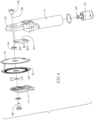
- FIG. 2 shows the example embodiment dehider tool having an outer sleeve and the stationary cutting disk removed, to reveal internal components of the dehider.
- This view shows a ring gear, bevel gear or face gear 52 on a face of the rotary cutting disk 16 driven by a drive member such as a pinion gear 40, as described in more detail below.
- an air valve body 26 contains an air valve that controls the flow of air to the dehider's air motor.
- the air valve body is fastened to the end of the handle section 12 by fasteners 28.
- Power for driving the rotary cutting disk 16 is provided by the air motor 30 contained in the handle section 12.
- the motor output shaft 31 drives a planetary gear assembly 32 engaged with a pinion gear 40.
- the planetary gear system provides gear reduction and torque control over the pinion gear.
- a motor end cap adapter 33 also shown in FIG. 3 are a motor end cap adapter 33, a valve lock ring 34 having spaced apart air passages, and a retaining-ring 36 used in coupling the valve body to the air motor.
- the air motor 30 is supported in the handle section 12 by a ball bearing 38, also shown in FIG. 3 .
- the planetary gear assembly 32 with pinion gear 40 is seated in the dehider housing via an O-ring 39.
- the air motor drives the planetary gear system which, in turn, drives the pinion gear 40 that rotates the cutting disk 16.
- the pinion gear 40 is one example of a drive member that can be a component of a drive mechanism or transmission for connecting the rotary power of a drive motor to the rotary-driven cutting disk 16.
- the cutting disks 16 and 18 are sandwiched between a rigid end plate section 42 integral with an end of the handle 12 and the cutting edge cover plate 14.
- the two cutting disks are supported at their centers on a common axis by a cutting disk shaft assembly 43 which includes a spacer 44 seated between the cover plate 14 and the end plate section 42 ( FIGS. 3 , 4 , 5 and 6 ).
- the spacer is ring member defining an opening 61.
- a load spring 45 is secured to the rotational axis adjacent the rotary cutting disk 16 for urging the rotary disk toward the stationary disk.
- the cutting edge spacer 44 is held in place between a cover insert and grease fitting (or “grease fitting") 46 at one end and a cover lock fastener 48 at the opposite end.
- the spacer 44 serves to space the cutting disks from the cover plate 14 and the end plate section 42. More specifically, in the example embodiment, the spacer 44 serves to space the cover plate 14 from the end plate section 42 such that they do not clamp on the cutting disks.
- the rotary cutting disk 16 has a flat inside face 50 that faces toward the adjacent stationary disk 18. In other example embodiments, the inside face 50 is not flat. For example, it may have a concave curvature.
- the rotary cutting disk 16 is driven by its connection to the pinion gear 40 which, in turn, is driven by the air motor 30.
- the rotary cutting disk 16 has an annular gear 52, as for example, a ring gear, a bevel gear, or a face gear formed by a gear teeth 54 extending along a circular path around the inside face of the rotary cutting disk, immediately inside its outer serrated cutting edge.
- the gear teeth on the pinion gear engage the gear teeth 54 on the gear 52 so that operation of the air motor drives the pinion to rotate the cutting disk 16 via the connection to the gear 52.
- a rigid frame cover 64 secured to an inside face of the end plate 42 by fasteners 66 ( FIGS. 3 , 4 , 5 and 6 ).
- a U-shaped projection 56 extends from a face of the rigid frame cover 64 facing away from the end plate section 42.
- the stationary disk also has a recessed or notched region 62 at its base to provide a space for receiving the pinion gear 40 such that the pinion gear accesses the gear teeth 54 on the rotary cutting disk.
- the U-shaped projection 56 is also received in the stationary disk notched region 62 and it is straddled by the notched region 62.
- the U-shaped projection is sized so as to prevent any rotation, or any significant notched, of the stationary disk about the axis 58.
- the stationary disk 18 is axially held in its stationary position adjacent the rotary cutting disk 16 by the grease fitting 46 and a cover lock fastener 48 which penetrate central openings 57, 59 of the stationary and rotary disks, respectively, as well as the opening 61 of the spacer 44.
- the spacer 44 also penetrates the central openings 57, 59 of the stationary and rotary disks, respectively.
- the stationary cutting disk is supported in its fixed upright position adjacent a rigid frame cover 64 secured to an inside face of the end plate 42 by fasteners 66.
- the stationary cutting disk may be completely stationary or in an example embodiment may have some minimum play as for example a minimum rotational play about the axis 58.
- the two cutting disks are mounted at the end of the handle with the rotary cutting disk adapted to be driven by the air motor's connection to the ring gear on the cutting disk 16, while the cutting disk 18 is held in its stationary position adjacent to the rotary cutting disk.
- the two cutting disks in the example embodiment have matching diameters and are mounted concentric to one another so that the serrated outer cutting edge edges of the two disks are closely spaced and face one another.
- the two cutting disks each have a 110 mm diameter with 48 cutting teeth around the cutting edge, although other sized disks can be used.
- the mounting arrangement for the two disks enables a shearing and cutting action applied to the carcass of an animal when the cutting disk 16 has its cutting edge rotating adjacent to the serrated cutting edge of the adjacent stationary cutting disk.
- the single rotary cutting edge adjacent the stationary cutting edge avoids vibration problems caused by the eccentric-driven oscillating cutting blades of prior art dehiders.
- the dehider includes a speed governor 70 positioned in the handle section and connected between the air inlet and the air motor.
- the speed governor automatically controls the flow of pressurized air from an air inlet to the motor to maintain a desired rotational speed for the motor.
- the speed governor smooths out the loads applied during use and adds a further level of vibration prevention by avoiding sudden no-load forces.
- the speed governor comprises one that operates by centrifugal force to restrict the flow of air to the motor to decrease motor speed when it exceeds a desired rotational speed.
- the governor includes a governor spring for biasing a valve away from a valve seat (to increase flow) and a movable mass that compresses the governor spring toward the valve seat (to restrict flow).
- the speed governor may be of the type that maintains the rpm of the rotary disk at a constant level which may be the same constant level when the dehider is being used to remove a hide and when the dehider is operating freely without being engaged onto a hide or other object.
- the governor may maintain a constant rpm of the rotary disk at the same constant level when the disks are loaded or unloaded.
- FIG. 9 is a perspective view showing an electric motor-driven handheld dehider tool 110 which includes an elongated handle section 112 that holds an edge cover 114 affixed to the handle section adjacent a pair of circular cutting disks 116 and 118.
- the cutting disks shown in FIG. 9 are mounted to the end of the handle section in a face-to-face relation similar to the cutting disks 16 and 18 described previously.
- the cutting disk 116 is a rotary disk
- the disk 118 is stationary
- the rotary cutting disk 116 is driven by an electric motor described in more detail below.
- the electric motor-driven dehider includes a cable quick-disconnect fitting 120 and a flexible power cable 122 extending from the electric motor used to drive the rotary disk 116.
- FIG. 10 shows the electric motor-driven dehider having the outer cover 112 of the handle section removed to reveal internal drive components including an elongated handle bushing 113 and a pinion gear 140 engaged with a ring gear, bevel gear or face gear 152 on a face of the rotary cutting disk 116.
- power for driving the rotary disk 116 is provided by a remote electric drive motor (not shown) coupled to the dehider by the flexible power cable 122.
- the power cable is detachably coupled to the terminal of the handle section by a quick-disconnect cable connector 120.
- the disconnect fitting is secured to a handle end cap 80 at the base of the handle section by a fastener 82.
- the electric motor drives an elongated flexible drive cable 84 positioned inside the bushing 113.
- the driven end of the flexible drive cable 84 is coupled to the pinion gear 140.
- a flexible cable jacket 86 in the form of a coiled sheet metal liner is sealed around the exterior of the flexible drive cable 84.
- the jacket carries a lubricant for the drive cable.
- the cutting disks 116 and 118 are mounted to the end of the handle section 112 similar to the air motor embodiment described previously.
- a load spring 145 is secured to the rotational axis adjacent the rotary disk 116 for urging the rotary disk toward the stationary disk.
- the cutting disks are sandwiched between a rigid end plate section 142 on the end of the handle 112 and a cover plate 114.
- the disks are supported at their centers on a common axis 158 by a cutting disk shaft assembly which includes an edge spacer 144 seated between the cover plate 114 and end plate section 142.
- the spacer 144 is a ring member defining a central opening 161.
- the spacer is held in place between a cover insert and grease fitting (or "grease fitting") 146 at one end and a cover lock fastener 148 at the opposite end.
- the grease fitting 146 and the cover lock fastener 148 penetrate the opening 161 of the spacer 144.
- the rotary cutting disk 116 has a flat inside face 150 that faces toward the adjacent stationary disk 118. In other example embodiments, the inside face 150 is not flat. For example, it may have a concave curvature.
- the rotary disk 116 is driven by the pinion gear 140 which, in turn, is driven by the drive cable 84.
- the rotary disk 116 has an annular gear 152, as for example, a ring gear, a bevel gear or a face gear formed by the gear teeth that extend around a circular path on the inside face of the disk.
- the gear teeth on the pinion gear engage the gear teeth on the annular gear 152 so that operation of the electric motor-driven cable 84 drives the pinion to rotate the cutting disk by the connection to the gear 152.
- a rigid frame cover 164 secured to an inside face of the end plate 142 by fasteners 166 ( FIGS. 11 , 12 , 13 and 14 ).
- a U-shaped projection 156 extends from a face of the rigid frame cover 164 facing away from the end plate section 142.
- the stationary disk also has a recessed or notched region 162 at its base to provide a space for receiving the pinion gear 140, such that the pinion gear accesses the gear teeth 154 on the rotary cutting disk.
- the U-shaped projection 156 is also received in the stationary disk notched region 162 and it is straddled by the notched region 162.
- the U-shaped projection is sized so as to prevent any rotation, or any significant rotation, of the stationary plate about the axis 158.
- the stationary disk 118 is axially held in its stationary position adjacent the rotary cutting disk 116 by the grease fitting 146 and a cover lock fastener 148 which penetrate central openings 157, 159 of the stationary and rotary disks, respectively, as well as the opening 161 of the spacer 144.
- the spacer 144 also penetrates the central openings 157, 159 of the stationary and rotary disks, respectively.
- the stationary cutting disk is supported in its fixed upright position adjacent a rigid frame cover 164 secured to an inside face of the end plate 142 by fasteners 166.
- the stationary cutting disk may be completely stationary or in an example embodiment may have some minimum play as for example a minimum rotational play about the axis 158.
- the two cutting disks 116 and 118 in an example embodiment have matching diameters and are mounted concentric to one another so that the serrated outer edge edges of the two disks are closely spaced and face one another.
- the two disks preferably have a 110 mm diameter with 48 cutting teeth around the edge edges, although other sized disks can be used.
- FIGS. 13-17 show views taken from different sides of the electric motor-driven dehider, and in particular, the flexible drive cable and its operative connection from the motor to the pinion gear 140.
- the electric motor in one embodiment can be a high speed, approximately 5000 rpm, AC single phase electric motor.
- the motor has sufficient power and torque with speed in the range necessary to produce a required cutting edge speed for the dehider.
- the air motor described previously, on the other hand can operate at about 20,000 rpm, and so the planetary gear reduction module is used to reduce speed to about 5000 rpm, while increasing torque to a sufficient level to accommodate the dehiding tasks.
- the electric motor-driven tool can be operated within the desired speed range by a direct connection between the rotating drive cable 84 and the pinion gear 140.
- the electric motor can be stationed remotely above ground adjacent the production line.
- the electrical power from the drive motor rotates the drive cable 84 about its axis.
- the drive cable is centered in the tubular jacket 86 and both extend axially along a tubular passageway 88 within the handle section.
- the passageway is preferably offset and parallel to the central axis of the handle section, as shown best in FIGS. 13 , 14 , and 17 .
- the driven end of the drive cable includes a square-shaped drive shaft 90 centered in a cooperating square shaped hole in the pinion gear 140.
- the driven end of the drive cable 84 is centered by a bearing 92 seated in the tubular passageway 88 in the handle section of the tool.
- the area 55, 155 ( FIGS. 6 and 14 ), where the pinion gear engages the annular gear 52, 152, is well within the tool and shielded from exposure to bone chips, meat and/or fat. Exposure of the gears to bone chips, meat and/or fat can disrupt the operation of the dehider and may also cause damage and/or failure to the dehider.
- the annular gear 52, 152 is within the pocket 99, 199, defined between the disks, which receives grease via the grease fitting 46, 146, and thus is properly lubricated.
- cutting disks 216 and 218 are mounted to the end of the handle section 212.
- This example may also be driven in various exemplary embodiments pneumatically or electrically as described with the previous embodiments, or may be driven by other drive mechanisms.
- a load spring 245 is secured to the rotational axis adjacent the stationary disk 218 for urging the stationary disk toward the rotary disk 216.
- the cutting disks are sandwiched between a rigid end plate section 242 on the end of the handle section 212 and a cover plate 214. In this embodiment, however, the rotary disk is closest to the handle section 212 whereas the stationary disk 218 is closest to the cover plate 214.
- the disks are supported at their centers on a common axis 258 by a cutting disk shaft assembly which includes an edge spacer 244 seated between the handle plate end section 212 and cover plate 214.
- the spacer 244 is a ring member defining a central opening 261.
- the spacer is held in place between a cover insert and grease fitting (or "grease fitting") 246 at one end and a cover lock fastener 248 at the opposite end.
- the grease fitting 246 and the cover lock fastener 248 penetrate the opening 261 of the spacer 244.
- the rotary cutting disk 216 has a flat inside face 250 that faces toward the adjacent stationary disk 218.
- the inside face 250 is not flat.
- the rotary disk 216 has an annular gear 252, as for example, a ring gear, a bevel gear or a face gear formed by the gear teeth that extend around a circular path on an outside face 253 of the disk.
- the gear teeth on the pinion gear engage the gear teeth of the annular gear 252 so that the pinion gear 250 rotate can rotate the cutting disk by the connection to the gear 252.
- the stationary disk 218 is prevented from rotating by pins 272 extending from the cover plate 214 which penetrated corresponding openings 273 formed on the stationary disk.
- the pins are also fitted in openings 275 in the cover plate 214.
- the pins 272 fit tightly into the openings 273 and 275 so as to prevent rotation and minimize rotational play of the stationary disk.
- the pins may be attached or integrally formed with either the cover plate or the stationary disk and penetrate the corresponding openings on the other of the cover plate and the stationary disk.
- the stationary disk is also axially held in its stationary position adjacent the rotary cutting disk 216 by the grease fitting 246 and a cover lock fastener 248 which penetrate central openings 257, 259 of the stationary and rotary disks, respectively, as well as the opening 261 of the spacer 244.
- the spacer 244 also penetrates the central openings 257, 259 of the stationary and rotary disks, respectively.
- the stationary cutting disk may be completely stationary or in an example embodiment may have some minimum play as for example a minimum rotational play about the axis 258.
- both the rotary disk and the stationary disk have serrated cutting edges 302, 304 as for example shown in FIG. 21 .
- the serrated edges are defined by triangular projections or serrations 306, 307, respectively.
- the serrations of the rotary cutting disk have opposite sides or edges 308, 309 and the stationary disk serration have opposite edges 310, 311.
- the edges 308 of the rotary cutting disk serrations leading in the direction of rotation 312 of the rotary disk are sharp defining the cutting edge 302 as are the edges 310 of the stationary disk serrations defining the cutting edge 302 which face opposite the direction of rotation 312 of the rotary disk.
- the sharp edge 308 of each rotary disk serration in combination with a sharp edge 310 of a stationary disk serration act like scissors, as for example shown in FIG. 21 .
- both edges 308, 309 of the rotary disk serrations are sharp.
- both sides 310, 311 of the stationary disk serrations are sharp.
- the tip 314 of each rotary disk serration and the tip 316 of each stationary disk serration is rounded or dull. In this regard, it is more difficult, and sometimes not possible, for the tips of the serrations to punch holes into the hide of the animal being dehided. Hides with holes in them have decreased value.
- the dehider avoids the use of prior art contra-oscillating blades and the related eccentric-driven pushrods which have caused vibration problems and related work place health problems such as carpal tunnels in the past.
- the dehider of this invention produces an effective scissor-like cutting action without the vibration problems; and the dehider has fewer parts, is lighter in weight, and lowers repair and operating costs.
Landscapes
- Engineering & Computer Science (AREA)
- Food Science & Technology (AREA)
- Life Sciences & Earth Sciences (AREA)
- Harvester Elements (AREA)
- Knives (AREA)
- Grinding-Machine Dressing And Accessory Apparatuses (AREA)
- Sawing (AREA)
- Scissors And Nippers (AREA)
- Food-Manufacturing Devices (AREA)
- Surgical Instruments (AREA)
- Furnace Housings, Linings, Walls, And Ceilings (AREA)
- Hand Tools For Fitting Together And Separating, Or Other Hand Tools (AREA)
- Pressure Welding/Diffusion-Bonding (AREA)
Applications Claiming Priority (2)
| Application Number | Priority Date | Filing Date | Title |
|---|---|---|---|
| US201361887297P | 2013-10-04 | 2013-10-04 | |
| PCT/US2014/058908 WO2015051180A1 (en) | 2013-10-04 | 2014-10-02 | Dehiding tool |
Publications (2)
| Publication Number | Publication Date |
|---|---|
| EP3051954A1 EP3051954A1 (en) | 2016-08-10 |
| EP3051954B1 true EP3051954B1 (en) | 2024-05-01 |
Family
ID=51830615
Family Applications (1)
| Application Number | Title | Priority Date | Filing Date |
|---|---|---|---|
| EP14790417.1A Active EP3051954B1 (en) | 2013-10-04 | 2014-10-02 | Dehiding tool |
Country Status (13)
| Country | Link |
|---|---|
| US (2) | US9615588B2 (ru) |
| EP (1) | EP3051954B1 (ru) |
| JP (1) | JP6553626B2 (ru) |
| CN (1) | CN105828617B (ru) |
| AR (1) | AR097913A1 (ru) |
| AU (1) | AU2014329418B2 (ru) |
| BR (1) | BR112016007307B1 (ru) |
| CA (1) | CA2926040C (ru) |
| MX (1) | MX371326B (ru) |
| NZ (1) | NZ718700A (ru) |
| RU (2) | RU2686985C2 (ru) |
| WO (1) | WO2015051180A1 (ru) |
| ZA (1) | ZA201602730B (ru) |
Families Citing this family (8)
| Publication number | Priority date | Publication date | Assignee | Title |
|---|---|---|---|---|
| US11026434B2 (en) | 2017-09-06 | 2021-06-08 | Bettcher Industries, Inc. | Power operated trimming tool |
| US10731713B1 (en) | 2019-01-18 | 2020-08-04 | Bettcher Industries, Inc. | Power operated trimming tool with clutch drive |
| CN109893207A (zh) * | 2019-04-23 | 2019-06-18 | 遵义医学院附属医院 | 一种脊柱内镜微创骨刀 |
| US11737395B2 (en) * | 2019-05-22 | 2023-08-29 | LPF Robotics, LLC | Apparatuses and methods for removing plant material |
| US11375723B2 (en) | 2019-05-22 | 2022-07-05 | Bettcher Industries, Inc. | Power operated scribe saw |
| USD912486S1 (en) * | 2019-05-23 | 2021-03-09 | Bettcher Industries Inc. | Dehiding tool |
| USD950352S1 (en) | 2019-10-07 | 2022-05-03 | Bettcher Industries, Inc. | Handle for a hand-held power operated tool |
| US11533919B2 (en) | 2020-07-21 | 2022-12-27 | Bettcher Industries, Inc. | Feed roll for power operated trimming tool |
Citations (1)
| Publication number | Priority date | Publication date | Assignee | Title |
|---|---|---|---|---|
| EP1403012A2 (en) * | 2001-01-24 | 2004-03-31 | Bettcher Industries, Inc. | Rotary knife |
Family Cites Families (40)
| Publication number | Priority date | Publication date | Assignee | Title |
|---|---|---|---|---|
| US1531406A (en) | 1922-05-06 | 1925-03-31 | Chicago Pneumatic Tool Co | Governor for fluid-pressure tools |
| GB686926A (en) * | 1950-10-02 | 1953-02-04 | William Jack O Neilly | Improvements in or relating to cutting, clipping and skinning tools |
| US2766524A (en) * | 1954-07-19 | 1956-10-16 | Depouille Mecanique Des Animau | Oscillating blade cutting apparatus, in particular for skinning slaughtered animals |
| US3048150A (en) | 1960-09-23 | 1962-08-07 | Herschal Products Inc | Pneumatically operated tool |
| DE1199156B (de) | 1962-02-22 | 1965-08-19 | Schmid & Wezel | Geraet zum Abhaeuten von Schlachttieren |
| US3165833A (en) * | 1962-11-27 | 1965-01-19 | Packers Dev Corp | Flaying tool |
| US3262199A (en) | 1964-06-04 | 1966-07-26 | Preco Inc | Air-powered cutting tool for hair and the like |
| US3587752A (en) | 1969-06-02 | 1971-06-28 | Black & Decker Mfg Co | Fluidic governor for air tools |
| US3857177A (en) | 1973-04-13 | 1974-12-31 | E Quintana | Dehiding apparatus |
| US3852882A (en) | 1974-01-28 | 1974-12-10 | Bettcher Industries | Air driven boning and trimming knives |
| US4215451A (en) * | 1979-05-10 | 1980-08-05 | Best & Donovan | Dehider |
| DE3020878A1 (de) * | 1980-06-02 | 1982-01-14 | Schmid & Wezel, 7133 Maulbronn | Schneidgeraet zum abhaeuten von schlachttieren |
| SE435641B (sv) | 1981-10-21 | 1984-10-08 | Atlas Copco Ab | Lufttillforselorgan vid ett pneumatiskt drivet handverktyg |
| US4575938A (en) | 1984-07-12 | 1986-03-18 | Mccullough Timothy J | Meat trimming knife |
| US4894915A (en) | 1986-03-20 | 1990-01-23 | Bettcher Industries, Inc. | Cable driven ring blade knife |
| US4797074A (en) | 1987-06-29 | 1989-01-10 | Ingersoll-Rand Company | Governor device |
| US4901400A (en) * | 1989-01-27 | 1990-02-20 | Karubian Ralph K | De-hiding tool |
| US5122092A (en) * | 1989-12-13 | 1992-06-16 | Jarvis Products Corporation | Power skinning knife with removable drive mechanism and high efficiency pneumatic motor |
| US5230154A (en) | 1990-09-28 | 1993-07-27 | Bettcher Industries, Inc. | Modular power-driven rotary knife, improved handle and method |
| DE4229134C2 (de) * | 1992-09-01 | 1994-07-14 | Schmid & Wezel | Rundmesserenthäuter |
| US5340233A (en) | 1992-10-07 | 1994-08-23 | M-B-W Inc. | Pneumatically operated rammer |
| US5311664A (en) | 1992-12-02 | 1994-05-17 | Jarvis Products Corporation | Power skinning knife with unidirectional rotating blade |
| US5441445A (en) * | 1993-09-09 | 1995-08-15 | Kentmaster Manufacturing Company, Inc. | De-hiding tool |
| US5522142A (en) | 1994-06-30 | 1996-06-04 | Bettcher Industries, Inc. | Rotary knife and slicing gauge |
| US5664332A (en) | 1996-02-14 | 1997-09-09 | Bettcher Industries, Inc. | Hand knife with cover |
| US5692307A (en) | 1996-06-28 | 1997-12-02 | Bettcher Industries, Inc. | Rotary knife blade |
| US5761817A (en) | 1996-10-17 | 1998-06-09 | Bettcher Industries, Inc. | Rotary hand knife |
| US6769184B1 (en) | 1998-07-22 | 2004-08-03 | Bettcher Industries, Inc. | Low friction rotary knife |
| EP1527853B1 (en) | 1999-10-06 | 2007-01-24 | Bettcher Industries, Inc. | Power operated rotary knife |
| WO2002030302A1 (en) | 2000-10-12 | 2002-04-18 | Alcon Inc. | Microsurgical instrument |
| US7163453B1 (en) | 2005-09-29 | 2007-01-16 | Jarvis Products Corporation | Dehider with dual counterbalance drive system |
| US7722448B2 (en) * | 2006-08-16 | 2010-05-25 | Jarvis Products Corporation | Dehider with governor and strengthened blade |
| JP4761290B2 (ja) | 2004-11-26 | 2011-08-31 | 株式会社ブリヂストン | 切断装置 |
| ES2688419T3 (es) * | 2005-09-29 | 2018-11-02 | Jarvis Products Corporation | Desolladora manual |
| WO2007057979A1 (ja) | 2005-11-18 | 2007-05-24 | Lozenstar Kabushiki Kaisha | 耳毛用カッター |
| US8448340B2 (en) | 2010-02-01 | 2013-05-28 | Bettcher Industries, Inc. | Large diameter notched blade and blade housing for power operated rotary knife |
| ITTO20110008U1 (it) | 2011-02-11 | 2012-08-12 | Sidel Spa Con Socio Unico | Gruppo lama statico |
| US8745881B2 (en) | 2011-07-25 | 2014-06-10 | Bettcher Industries, Inc. | Power operated rotary knife |
| US8806761B2 (en) | 2011-07-25 | 2014-08-19 | Bettcher Industries, Inc. | Power operated rotary knife |
| US8905827B1 (en) * | 2013-03-14 | 2014-12-09 | Dale R. Ross | Dehider tool and blade therefor |
-
2014
- 2014-10-02 CN CN201480066539.5A patent/CN105828617B/zh active Active
- 2014-10-02 MX MX2016004225A patent/MX371326B/es active IP Right Grant
- 2014-10-02 CA CA2926040A patent/CA2926040C/en active Active
- 2014-10-02 BR BR112016007307-0A patent/BR112016007307B1/pt active IP Right Grant
- 2014-10-02 WO PCT/US2014/058908 patent/WO2015051180A1/en active Application Filing
- 2014-10-02 NZ NZ718700A patent/NZ718700A/en unknown
- 2014-10-02 RU RU2018132524A patent/RU2686985C2/ru active
- 2014-10-02 RU RU2016116908A patent/RU2016116908A/ru unknown
- 2014-10-02 US US14/505,419 patent/US9615588B2/en active Active
- 2014-10-02 EP EP14790417.1A patent/EP3051954B1/en active Active
- 2014-10-02 AU AU2014329418A patent/AU2014329418B2/en active Active
- 2014-10-02 JP JP2016546885A patent/JP6553626B2/ja active Active
- 2014-10-03 AR ARP140103692A patent/AR097913A1/es active IP Right Grant
-
2016
- 2016-04-20 ZA ZA2016/02730A patent/ZA201602730B/en unknown
-
2017
- 2017-02-02 US US15/423,381 patent/US9913482B2/en active Active
Patent Citations (1)
| Publication number | Priority date | Publication date | Assignee | Title |
|---|---|---|---|---|
| EP1403012A2 (en) * | 2001-01-24 | 2004-03-31 | Bettcher Industries, Inc. | Rotary knife |
Also Published As
| Publication number | Publication date |
|---|---|
| US20170142986A1 (en) | 2017-05-25 |
| WO2015051180A1 (en) | 2015-04-09 |
| BR112016007307A2 (pt) | 2017-08-01 |
| US9913482B2 (en) | 2018-03-13 |
| AR097913A1 (es) | 2016-04-20 |
| US20150099442A1 (en) | 2015-04-09 |
| BR112016007307B1 (pt) | 2021-11-23 |
| US9615588B2 (en) | 2017-04-11 |
| NZ718700A (en) | 2021-07-30 |
| ZA201602730B (en) | 2018-12-19 |
| MX371326B (es) | 2020-01-27 |
| JP2016536007A (ja) | 2016-11-24 |
| AU2014329418A1 (en) | 2016-04-21 |
| AU2014329418B2 (en) | 2018-11-29 |
| CA2926040A1 (en) | 2015-04-09 |
| RU2018132524A (ru) | 2018-11-14 |
| CN105828617A (zh) | 2016-08-03 |
| CA2926040C (en) | 2020-06-23 |
| RU2016116908A (ru) | 2017-11-09 |
| JP6553626B2 (ja) | 2019-07-31 |
| RU2686985C2 (ru) | 2019-05-06 |
| EP3051954A1 (en) | 2016-08-10 |
| CN105828617B (zh) | 2018-04-06 |
| RU2018132524A3 (ru) | 2019-02-13 |
| MX2016004225A (es) | 2016-11-25 |
Similar Documents
| Publication | Publication Date | Title |
|---|---|---|
| US9913482B2 (en) | Dehiding tool | |
| US7207114B2 (en) | Rotary knife with improved drive transmission | |
| US5761817A (en) | Rotary hand knife | |
| US6945862B2 (en) | Power tool having a receptacle for securing a tool | |
| EP1302282B1 (en) | Pneumatic hand tool with improved control valve | |
| EP2473019B1 (en) | Cutting assembly for hand-held power tool | |
| US11284568B2 (en) | Hedge trimmer | |
| US4312610A (en) | Sheet material cutting device | |
| US10471525B2 (en) | Reciprocating saw mechanism | |
| US9962779B2 (en) | Counterweight device | |
| AU2017370545B2 (en) | Dehider regulator valve | |
| EP2853345A2 (en) | Grinders with friction drives | |
| WO2021116076A8 (de) | Elektrische handwerkzeugmaschine | |
| EP2910340A1 (en) | Clutch for electric tool, method of manufacturing the tool and method of operating the tool | |
| US5020606A (en) | Reciprocating rotary tool driver | |
| RU2376772C1 (ru) | Ручной шкуросъемный нож | |
| US20190134802A1 (en) | Handheld Power Tool | |
| CN113453831A (zh) | 用于切割混凝土和石材并包括用于驱动圆形切割工具的驱动装置的手持切割锯 | |
| UA28406U (en) | Clippers |
Legal Events
| Date | Code | Title | Description |
|---|---|---|---|
| PUAI | Public reference made under article 153(3) epc to a published international application that has entered the european phase |
Free format text: ORIGINAL CODE: 0009012 |
|
| 17P | Request for examination filed |
Effective date: 20160502 |
|
| AK | Designated contracting states |
Kind code of ref document: A1 Designated state(s): AL AT BE BG CH CY CZ DE DK EE ES FI FR GB GR HR HU IE IS IT LI LT LU LV MC MK MT NL NO PL PT RO RS SE SI SK SM TR |
|
| AX | Request for extension of the european patent |
Extension state: BA ME |
|
| DAX | Request for extension of the european patent (deleted) | ||
| STAA | Information on the status of an ep patent application or granted ep patent |
Free format text: STATUS: EXAMINATION IS IN PROGRESS |
|
| 17Q | First examination report despatched |
Effective date: 20170529 |
|
| STAA | Information on the status of an ep patent application or granted ep patent |
Free format text: STATUS: EXAMINATION IS IN PROGRESS |
|
| STAA | Information on the status of an ep patent application or granted ep patent |
Free format text: STATUS: EXAMINATION IS IN PROGRESS |
|
| GRAP | Despatch of communication of intention to grant a patent |
Free format text: ORIGINAL CODE: EPIDOSNIGR1 |
|
| STAA | Information on the status of an ep patent application or granted ep patent |
Free format text: STATUS: GRANT OF PATENT IS INTENDED |
|
| INTG | Intention to grant announced |
Effective date: 20230731 |
|
| GRAS | Grant fee paid |
Free format text: ORIGINAL CODE: EPIDOSNIGR3 |
|
| GRAA | (expected) grant |
Free format text: ORIGINAL CODE: 0009210 |
|
| STAA | Information on the status of an ep patent application or granted ep patent |
Free format text: STATUS: THE PATENT HAS BEEN GRANTED |
|
| AK | Designated contracting states |
Kind code of ref document: B1 Designated state(s): AL AT BE BG CH CY CZ DE DK EE ES FI FR GB GR HR HU IE IS IT LI LT LU LV MC MK MT NL NO PL PT RO RS SE SI SK SM TR |
|
| REG | Reference to a national code |
Ref country code: GB Ref legal event code: FG4D |
|
| REG | Reference to a national code |
Ref country code: CH Ref legal event code: EP |
|
| REG | Reference to a national code |
Ref country code: IE Ref legal event code: FG4D |
|
| REG | Reference to a national code |
Ref country code: DE Ref legal event code: R096 Ref document number: 602014090091 Country of ref document: DE |