EP3051657B1 - Battery charge and discharge control system and battery charge and discharge control method - Google Patents
Battery charge and discharge control system and battery charge and discharge control method Download PDFInfo
- Publication number
- EP3051657B1 EP3051657B1 EP16153361.7A EP16153361A EP3051657B1 EP 3051657 B1 EP3051657 B1 EP 3051657B1 EP 16153361 A EP16153361 A EP 16153361A EP 3051657 B1 EP3051657 B1 EP 3051657B1
- Authority
- EP
- European Patent Office
- Prior art keywords
- soc
- battery
- battery pack
- socs
- battery packs
- Prior art date
- Legal status (The legal status is an assumption and is not a legal conclusion. Google has not performed a legal analysis and makes no representation as to the accuracy of the status listed.)
- Active
Links
- 238000000034 method Methods 0.000 title claims description 34
- 238000007600 charging Methods 0.000 claims description 27
- 238000010278 pulse charging Methods 0.000 claims description 3
- 238000007599 discharging Methods 0.000 description 25
- 230000006866 deterioration Effects 0.000 description 14
- 238000012545 processing Methods 0.000 description 13
- 238000005259 measurement Methods 0.000 description 5
- 230000002411 adverse Effects 0.000 description 3
- 230000000052 comparative effect Effects 0.000 description 3
- 230000007423 decrease Effects 0.000 description 3
- 230000002542 deteriorative effect Effects 0.000 description 2
- 238000004146 energy storage Methods 0.000 description 2
- 239000000446 fuel Substances 0.000 description 2
- 239000000126 substance Substances 0.000 description 2
- 238000013459 approach Methods 0.000 description 1
- 230000015556 catabolic process Effects 0.000 description 1
- 238000006731 degradation reaction Methods 0.000 description 1
- 230000001419 dependent effect Effects 0.000 description 1
- 238000002474 experimental method Methods 0.000 description 1
Images


Classifications
-
- H—ELECTRICITY
- H02—GENERATION; CONVERSION OR DISTRIBUTION OF ELECTRIC POWER
- H02J—CIRCUIT ARRANGEMENTS OR SYSTEMS FOR SUPPLYING OR DISTRIBUTING ELECTRIC POWER; SYSTEMS FOR STORING ELECTRIC ENERGY
- H02J7/00—Circuit arrangements for charging or depolarising batteries or for supplying loads from batteries
- H02J7/0013—Circuit arrangements for charging or depolarising batteries or for supplying loads from batteries acting upon several batteries simultaneously or sequentially
- H02J7/0014—Circuits for equalisation of charge between batteries
-
- B—PERFORMING OPERATIONS; TRANSPORTING
- B60—VEHICLES IN GENERAL
- B60L—PROPULSION OF ELECTRICALLY-PROPELLED VEHICLES; SUPPLYING ELECTRIC POWER FOR AUXILIARY EQUIPMENT OF ELECTRICALLY-PROPELLED VEHICLES; ELECTRODYNAMIC BRAKE SYSTEMS FOR VEHICLES IN GENERAL; MAGNETIC SUSPENSION OR LEVITATION FOR VEHICLES; MONITORING OPERATING VARIABLES OF ELECTRICALLY-PROPELLED VEHICLES; ELECTRIC SAFETY DEVICES FOR ELECTRICALLY-PROPELLED VEHICLES
- B60L3/00—Electric devices on electrically-propelled vehicles for safety purposes; Monitoring operating variables, e.g. speed, deceleration or energy consumption
- B60L3/0023—Detecting, eliminating, remedying or compensating for drive train abnormalities, e.g. failures within the drive train
- B60L3/0046—Detecting, eliminating, remedying or compensating for drive train abnormalities, e.g. failures within the drive train relating to electric energy storage systems, e.g. batteries or capacitors
-
- B—PERFORMING OPERATIONS; TRANSPORTING
- B60—VEHICLES IN GENERAL
- B60L—PROPULSION OF ELECTRICALLY-PROPELLED VEHICLES; SUPPLYING ELECTRIC POWER FOR AUXILIARY EQUIPMENT OF ELECTRICALLY-PROPELLED VEHICLES; ELECTRODYNAMIC BRAKE SYSTEMS FOR VEHICLES IN GENERAL; MAGNETIC SUSPENSION OR LEVITATION FOR VEHICLES; MONITORING OPERATING VARIABLES OF ELECTRICALLY-PROPELLED VEHICLES; ELECTRIC SAFETY DEVICES FOR ELECTRICALLY-PROPELLED VEHICLES
- B60L58/00—Methods or circuit arrangements for monitoring or controlling batteries or fuel cells, specially adapted for electric vehicles
- B60L58/10—Methods or circuit arrangements for monitoring or controlling batteries or fuel cells, specially adapted for electric vehicles for monitoring or controlling batteries
- B60L58/12—Methods or circuit arrangements for monitoring or controlling batteries or fuel cells, specially adapted for electric vehicles for monitoring or controlling batteries responding to state of charge [SoC]
- B60L58/13—Maintaining the SoC within a determined range
-
- B—PERFORMING OPERATIONS; TRANSPORTING
- B60—VEHICLES IN GENERAL
- B60L—PROPULSION OF ELECTRICALLY-PROPELLED VEHICLES; SUPPLYING ELECTRIC POWER FOR AUXILIARY EQUIPMENT OF ELECTRICALLY-PROPELLED VEHICLES; ELECTRODYNAMIC BRAKE SYSTEMS FOR VEHICLES IN GENERAL; MAGNETIC SUSPENSION OR LEVITATION FOR VEHICLES; MONITORING OPERATING VARIABLES OF ELECTRICALLY-PROPELLED VEHICLES; ELECTRIC SAFETY DEVICES FOR ELECTRICALLY-PROPELLED VEHICLES
- B60L58/00—Methods or circuit arrangements for monitoring or controlling batteries or fuel cells, specially adapted for electric vehicles
- B60L58/10—Methods or circuit arrangements for monitoring or controlling batteries or fuel cells, specially adapted for electric vehicles for monitoring or controlling batteries
- B60L58/16—Methods or circuit arrangements for monitoring or controlling batteries or fuel cells, specially adapted for electric vehicles for monitoring or controlling batteries responding to battery ageing, e.g. to the number of charging cycles or the state of health [SoH]
-
- B—PERFORMING OPERATIONS; TRANSPORTING
- B60—VEHICLES IN GENERAL
- B60L—PROPULSION OF ELECTRICALLY-PROPELLED VEHICLES; SUPPLYING ELECTRIC POWER FOR AUXILIARY EQUIPMENT OF ELECTRICALLY-PROPELLED VEHICLES; ELECTRODYNAMIC BRAKE SYSTEMS FOR VEHICLES IN GENERAL; MAGNETIC SUSPENSION OR LEVITATION FOR VEHICLES; MONITORING OPERATING VARIABLES OF ELECTRICALLY-PROPELLED VEHICLES; ELECTRIC SAFETY DEVICES FOR ELECTRICALLY-PROPELLED VEHICLES
- B60L58/00—Methods or circuit arrangements for monitoring or controlling batteries or fuel cells, specially adapted for electric vehicles
- B60L58/10—Methods or circuit arrangements for monitoring or controlling batteries or fuel cells, specially adapted for electric vehicles for monitoring or controlling batteries
- B60L58/18—Methods or circuit arrangements for monitoring or controlling batteries or fuel cells, specially adapted for electric vehicles for monitoring or controlling batteries of two or more battery modules
- B60L58/19—Switching between serial connection and parallel connection of battery modules
-
- B—PERFORMING OPERATIONS; TRANSPORTING
- B60—VEHICLES IN GENERAL
- B60L—PROPULSION OF ELECTRICALLY-PROPELLED VEHICLES; SUPPLYING ELECTRIC POWER FOR AUXILIARY EQUIPMENT OF ELECTRICALLY-PROPELLED VEHICLES; ELECTRODYNAMIC BRAKE SYSTEMS FOR VEHICLES IN GENERAL; MAGNETIC SUSPENSION OR LEVITATION FOR VEHICLES; MONITORING OPERATING VARIABLES OF ELECTRICALLY-PROPELLED VEHICLES; ELECTRIC SAFETY DEVICES FOR ELECTRICALLY-PROPELLED VEHICLES
- B60L58/00—Methods or circuit arrangements for monitoring or controlling batteries or fuel cells, specially adapted for electric vehicles
- B60L58/10—Methods or circuit arrangements for monitoring or controlling batteries or fuel cells, specially adapted for electric vehicles for monitoring or controlling batteries
- B60L58/18—Methods or circuit arrangements for monitoring or controlling batteries or fuel cells, specially adapted for electric vehicles for monitoring or controlling batteries of two or more battery modules
- B60L58/21—Methods or circuit arrangements for monitoring or controlling batteries or fuel cells, specially adapted for electric vehicles for monitoring or controlling batteries of two or more battery modules having the same nominal voltage
-
- H—ELECTRICITY
- H01—ELECTRIC ELEMENTS
- H01M—PROCESSES OR MEANS, e.g. BATTERIES, FOR THE DIRECT CONVERSION OF CHEMICAL ENERGY INTO ELECTRICAL ENERGY
- H01M10/00—Secondary cells; Manufacture thereof
- H01M10/42—Methods or arrangements for servicing or maintenance of secondary cells or secondary half-cells
- H01M10/4207—Methods or arrangements for servicing or maintenance of secondary cells or secondary half-cells for several batteries or cells simultaneously or sequentially
-
- H—ELECTRICITY
- H01—ELECTRIC ELEMENTS
- H01M—PROCESSES OR MEANS, e.g. BATTERIES, FOR THE DIRECT CONVERSION OF CHEMICAL ENERGY INTO ELECTRICAL ENERGY
- H01M10/00—Secondary cells; Manufacture thereof
- H01M10/42—Methods or arrangements for servicing or maintenance of secondary cells or secondary half-cells
- H01M10/44—Methods for charging or discharging
- H01M10/441—Methods for charging or discharging for several batteries or cells simultaneously or sequentially
-
- H02J7/0026—
-
- H—ELECTRICITY
- H02—GENERATION; CONVERSION OR DISTRIBUTION OF ELECTRIC POWER
- H02J—CIRCUIT ARRANGEMENTS OR SYSTEMS FOR SUPPLYING OR DISTRIBUTING ELECTRIC POWER; SYSTEMS FOR STORING ELECTRIC ENERGY
- H02J7/00—Circuit arrangements for charging or depolarising batteries or for supplying loads from batteries
- H02J7/0047—Circuit arrangements for charging or depolarising batteries or for supplying loads from batteries with monitoring or indicating devices or circuits
- H02J7/0048—Detection of remaining charge capacity or state of charge [SOC]
-
- H—ELECTRICITY
- H02—GENERATION; CONVERSION OR DISTRIBUTION OF ELECTRIC POWER
- H02J—CIRCUIT ARRANGEMENTS OR SYSTEMS FOR SUPPLYING OR DISTRIBUTING ELECTRIC POWER; SYSTEMS FOR STORING ELECTRIC ENERGY
- H02J7/00—Circuit arrangements for charging or depolarising batteries or for supplying loads from batteries
- H02J7/0047—Circuit arrangements for charging or depolarising batteries or for supplying loads from batteries with monitoring or indicating devices or circuits
- H02J7/005—Detection of state of health [SOH]
-
- H—ELECTRICITY
- H02—GENERATION; CONVERSION OR DISTRIBUTION OF ELECTRIC POWER
- H02J—CIRCUIT ARRANGEMENTS OR SYSTEMS FOR SUPPLYING OR DISTRIBUTING ELECTRIC POWER; SYSTEMS FOR STORING ELECTRIC ENERGY
- H02J7/00—Circuit arrangements for charging or depolarising batteries or for supplying loads from batteries
- H02J7/34—Parallel operation in networks using both storage and other dc sources, e.g. providing buffering
- H02J7/342—The other DC source being a battery actively interacting with the first one, i.e. battery to battery charging
-
- B—PERFORMING OPERATIONS; TRANSPORTING
- B60—VEHICLES IN GENERAL
- B60L—PROPULSION OF ELECTRICALLY-PROPELLED VEHICLES; SUPPLYING ELECTRIC POWER FOR AUXILIARY EQUIPMENT OF ELECTRICALLY-PROPELLED VEHICLES; ELECTRODYNAMIC BRAKE SYSTEMS FOR VEHICLES IN GENERAL; MAGNETIC SUSPENSION OR LEVITATION FOR VEHICLES; MONITORING OPERATING VARIABLES OF ELECTRICALLY-PROPELLED VEHICLES; ELECTRIC SAFETY DEVICES FOR ELECTRICALLY-PROPELLED VEHICLES
- B60L2240/00—Control parameters of input or output; Target parameters
- B60L2240/40—Drive Train control parameters
- B60L2240/54—Drive Train control parameters related to batteries
- B60L2240/545—Temperature
-
- B—PERFORMING OPERATIONS; TRANSPORTING
- B60—VEHICLES IN GENERAL
- B60L—PROPULSION OF ELECTRICALLY-PROPELLED VEHICLES; SUPPLYING ELECTRIC POWER FOR AUXILIARY EQUIPMENT OF ELECTRICALLY-PROPELLED VEHICLES; ELECTRODYNAMIC BRAKE SYSTEMS FOR VEHICLES IN GENERAL; MAGNETIC SUSPENSION OR LEVITATION FOR VEHICLES; MONITORING OPERATING VARIABLES OF ELECTRICALLY-PROPELLED VEHICLES; ELECTRIC SAFETY DEVICES FOR ELECTRICALLY-PROPELLED VEHICLES
- B60L2240/00—Control parameters of input or output; Target parameters
- B60L2240/40—Drive Train control parameters
- B60L2240/54—Drive Train control parameters related to batteries
- B60L2240/547—Voltage
-
- B—PERFORMING OPERATIONS; TRANSPORTING
- B60—VEHICLES IN GENERAL
- B60L—PROPULSION OF ELECTRICALLY-PROPELLED VEHICLES; SUPPLYING ELECTRIC POWER FOR AUXILIARY EQUIPMENT OF ELECTRICALLY-PROPELLED VEHICLES; ELECTRODYNAMIC BRAKE SYSTEMS FOR VEHICLES IN GENERAL; MAGNETIC SUSPENSION OR LEVITATION FOR VEHICLES; MONITORING OPERATING VARIABLES OF ELECTRICALLY-PROPELLED VEHICLES; ELECTRIC SAFETY DEVICES FOR ELECTRICALLY-PROPELLED VEHICLES
- B60L2240/00—Control parameters of input or output; Target parameters
- B60L2240/40—Drive Train control parameters
- B60L2240/54—Drive Train control parameters related to batteries
- B60L2240/549—Current
-
- H—ELECTRICITY
- H02—GENERATION; CONVERSION OR DISTRIBUTION OF ELECTRIC POWER
- H02J—CIRCUIT ARRANGEMENTS OR SYSTEMS FOR SUPPLYING OR DISTRIBUTING ELECTRIC POWER; SYSTEMS FOR STORING ELECTRIC ENERGY
- H02J7/00—Circuit arrangements for charging or depolarising batteries or for supplying loads from batteries
- H02J7/34—Parallel operation in networks using both storage and other dc sources, e.g. providing buffering
-
- Y—GENERAL TAGGING OF NEW TECHNOLOGICAL DEVELOPMENTS; GENERAL TAGGING OF CROSS-SECTIONAL TECHNOLOGIES SPANNING OVER SEVERAL SECTIONS OF THE IPC; TECHNICAL SUBJECTS COVERED BY FORMER USPC CROSS-REFERENCE ART COLLECTIONS [XRACs] AND DIGESTS
- Y02—TECHNOLOGIES OR APPLICATIONS FOR MITIGATION OR ADAPTATION AGAINST CLIMATE CHANGE
- Y02E—REDUCTION OF GREENHOUSE GAS [GHG] EMISSIONS, RELATED TO ENERGY GENERATION, TRANSMISSION OR DISTRIBUTION
- Y02E60/00—Enabling technologies; Technologies with a potential or indirect contribution to GHG emissions mitigation
- Y02E60/10—Energy storage using batteries
-
- Y—GENERAL TAGGING OF NEW TECHNOLOGICAL DEVELOPMENTS; GENERAL TAGGING OF CROSS-SECTIONAL TECHNOLOGIES SPANNING OVER SEVERAL SECTIONS OF THE IPC; TECHNICAL SUBJECTS COVERED BY FORMER USPC CROSS-REFERENCE ART COLLECTIONS [XRACs] AND DIGESTS
- Y02—TECHNOLOGIES OR APPLICATIONS FOR MITIGATION OR ADAPTATION AGAINST CLIMATE CHANGE
- Y02T—CLIMATE CHANGE MITIGATION TECHNOLOGIES RELATED TO TRANSPORTATION
- Y02T10/00—Road transport of goods or passengers
- Y02T10/60—Other road transportation technologies with climate change mitigation effect
- Y02T10/70—Energy storage systems for electromobility, e.g. batteries
Definitions
- One or more embodiments described herein relate to a battery charge and discharge control system and a battery charge and discharge control method.
- a mobile device may operate based on power from a rechargeable battery pack.
- the battery pack may be frequently charged.
- Another approach involves using two battery packs to power one mobile device.
- the two battery packs may have the same size and chemical properties.
- Each battery pack may have a control circuit and a fuel gauge circuit or a microcomputer.
- the fuel gauge circuit or microprocessor calculate the capacity of the battery pack.
- these circuits increase the price of the battery pack.
- two battery packs used for one device may have the same shape, chemical properties, the capacity, and charge voltage or charge current. This increases size and lowers energy efficiency per volume.
- a battery may experience less deterioration when not in use and may experience greater deterioration when in use.
- the battery may be used at a low rate rather than a high rate.
- the battery may only be used when in a better state of charge (SOC) state.
- the invention concerns a battery charge and discharge control method according to claim 1 and a system according to claim 7.
- the system, the method and the apparatus, respectively may comprise features as specified in the dependent claims.
- FIG. 1 illustrates an embodiment of a battery charge and discharge control system 100 which includes a first battery pack 110, a second battery pack 120, a state-of-charge (SOC) measuring unit 130, and a charge and discharge controller 140.
- the first battery pack 110 and the second battery pack 120 are connected in parallel.
- two battery packs 110 and 120 are illustrated.
- three or more battery packs may be connected in parallel, for example, depending on system requirements to increase capacity.
- a plurality of battery groups including a plurality of battery packs connected in series may be connected in parallel to increase capacity and an output voltage.
- Adjusting the SOCs of the first and second battery packs 110 and 120 so that the difference between the SOC of the first battery pack 110 and the SOC of the second battery pack 120 becomes 20% is only one example.
- the difference may correspond to a different value in another embodiment.
- the SOC of the first battery pack 110 and the SOC of the second battery pack 120 are each 50% before the adjustment, the SOC of one of the first or second battery packs 110 and 120 may be adjusted to be 40% and the SOC of the other may be adjusted to be 60%.
- the charge and discharge controller 140 adjusts the SOCs of the first and second battery packs 110 and 120 so that the sum of a difference between the SOC of the first battery pack 110 after the adjustment and a first reference value and a difference between the SOC of the second battery pack 120 after the adjustment and the first reference value is a predetermined value, e.g., is maximized.
- the first reference value may be an SOC value for reducing or minimizing lifetimes of the first and second battery packs 110 and 120.
- the lifetime of a battery pack may vary depending on the SOC of the battery pack.
- An SOC which increases or maximizes lifetime may vary, for example, depending on the type of battery packs.
- the SOC may decrease or increase by a certain percentage according to use of the battery pack.
- the SOC of the battery pack may be adjusted so that the battery pack operates in an SOC section where the battery pack has relatively better lifetime characteristics.
- the battery pack may not be used in an SOC section that is disadvantageous to the lifetime characteristics of the battery pack, even if the SOC decreases or increases, by taking into account the amount of increase or decrease of the SOC.
- the SOC of the first battery pack 110 and the SOC of the second battery pack 120 may be adjusted to be different from 50% in order to increase the lifetimes of the first and second battery packs 110 and 112.
- the SOC of the first battery pack 110 and the SOC of the second battery pack 120 may be adjusted to be 40% and 60%, respectively, in order to increase the lifetimes of the first and second battery packs 110 and 112.
- the SOC of the first battery pack 110 and the SOC of the second battery pack 120 may be adjusted to be 35% and 65%, respectively.
- the charge and discharge controller 140 may charge or discharge the first and second battery packs 110 and 120 so that the difference between the SOC of the first battery pack 110 and the SOC of the second battery pack 120 is less than or equal to the second threshold value.
- the charge and discharge controller 140 may adjust the SOCs of the first and second battery packs 110 and 120 so that the difference between the SOC of the first battery pack 110 and the SOC of the second battery pack 120 is less than or equal to 40%.
- the SOC of the first battery pack 110 and the SOC of the second battery pack 120 may be 72.5% and 32.5%, respectively. Accordingly, an average of the SOCs of the first and second battery packs 110 and 120 before the adjustment may be equal to an average of the SOCs of the first and second battery packs 110 and 120 after the adjustment.
- the charge and discharge controller 140 may charge or discharge, with a first C-rate, the first battery pack 110 and the second battery pack 120 after adjusting the SOCs of the first and second battery packs 120 using the method described above.
- C-rate corresponds to a current rate and is a unit for setting a current value under various using conditions during charging and discharging of a battery and for estimating or denoting an available using time of the battery.
- a current value according to a charge and discharge rate may be calculated by dividing a charge or discharge current by the rated capacity of the battery.
- the term "C" is used as the unit of the C-rate.
- the battery charge and discharge control system 100 sets a C-rate value to be used when charging and discharging a battery pack, based on a C-rate value by which the lifetime of the battery pack is increased or maximized. Even if a high current is applied through a pulse charge and discharge, rather than a continuous charge and discharge, deterioration of a battery may be suppressed and the lifetime of the battery may be lengthened.
- the battery charge and discharge control system 100 may include a first switch SW1 and a second switch SW2.
- the first switch SW1 is turned on or turned off based on a first control signal from the charge and discharge controller 140 to charge or discharge the first battery pack 110.
- the second switch SW2 is turned on or turned off based on a second control signal from the charge and discharge controller 140 to charge or discharge the second battery pack 120.
- the charge and discharge controller 140 may charge or discharge the first and second battery packs 110 and 120 so that the difference between the SOC of the first battery pack 110 and the SOC of the second battery pack 120 is equal to the second threshold value.
- the second threshold value may be a value not less than the first threshold value and, for example, may be equal to the first threshold value.
- the battery charge and discharge control system 100 sets an appropriate SOC difference between a plurality of battery packs and adjusts an SOC difference between or among the battery packs to the set SOC difference when the SOC difference between the battery packs, measured by the SOC measuring unit 130, is different from the set SOC difference.
- the first threshold value may be a reference value for increasing an SOC difference between battery packs having a small SOC difference therebetween.
- the second threshold value may be a reference value for reducing an SOC difference between battery packs having a large SOC difference therebetween.
- Each of the first and second threshold values may include an offset.
- an operation for adjusting SOCs of battery packs may not be performed when an SOC difference between the battery packs is equal to or greater than 38% and is equal to or less than 42%.
- the SOC difference between the battery packs is less than 38%, the SOC difference may be increased so that the SOC difference between the battery packs is 40%.
- the SOC difference between the battery packs is greater than 42%, the SOC difference may be reduced so that the SOC difference between the battery packs is 40%.
- the charge and discharge controller 140 may not adjust the SOCs of the first and second battery packs 110 and 120. Accordingly, even if an SOC difference between the first battery pack 110 and the second battery pack 120 is equal to or less than the first threshold value or is equal to or greater than the second threshold value, the charge and discharge controller 140 does not adjust the SOCs of the first and second battery packs 110 and 120 when the SOC of any one of the first and second battery packs 110 and 120 is equal to or less than 10% or is equal to or greater than 90%.
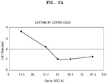
- the lifetime of the battery is shortest when the center SOC is set to 50% and the SOC is in a range between 37.5% and 62.5%.
- the lifetime of the battery is increased when the battery is used in a section where the SOC is less than 50%, and the lifetime of the battery is also increased when the battery is used in a section where the SOC is greater than 50%. Accordingly, in the case of a battery having SOC-lifetime characteristics as in FIG. 2A , a relatively long lifetime may be secured when the battery is used in a section where the SOC is not 50%.
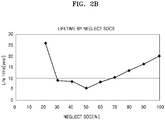
- the two graphs of FIGS. 2A and 2B illustrate results measured with respect to a battery of a certain type, and the SOC-lifetime characteristics in FIGS. 2A and 2B are just examples. Different measurements or characteristics may obtain for other embodiments.
- the SOC-lifetime characteristics of a battery may be obtained, for example, through repeated measurements based on the type of the battery.
- an SOC section may be set in which the battery is not to be used according to measured results, and use the battery may be used in a section other than the set section to secure a relatively long lifetime.
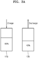
- FIGS. 3A and 3B illustrate examples of operations of one embodiment of a method for adjusting the SOC of a battery pack.
- the first battery pack 110 and a second battery pack 120 are illustrated in FIGS. 3A and 3B .
- FIG. 3A illustrates states of the first and second battery packs 110 and 120 before SOCs of the first and second battery packs 110 and 120 are adjusted.
- FIG. 3B illustrates states of the first and second battery packs 110 and 120 after the SOCs of the first and second battery packs 110 and 120 are adjusted.
- a first threshold value is set to 30% and a first reference value (e.g., an SOC by which lifetimes of the first and second battery packs 110 are minimized) is 50%, is described as an example.
- the SOC of the first battery pack 110 and the SOC of the second battery pack 120 are 60% and 40%, respectively, before the SOCs of the first and second battery packs 110 and 120 are adjusted.
- the SOC of the first battery pack 110 and the SOC of the second battery pack 120 are 70% and 30%, respectively, after the SOCs of the first and second battery packs 110 and 120 are adjusted.
- the charge and discharge controller 140 adjusts the SOCs of the first and second battery packs 110 and 120 so that the SOC of the first battery pack 110 is 70% after charging the first battery pack 110 and the SOC of the second battery pack 120 is 30% after discharging the second battery pack 120
- the charge and discharge controller 140 may adjusts the SOCs of the first and second battery packs 110 and 120 so that the SOC of the first battery pack 110 and the SOC of the second battery pack 120 are 37.5% and 67.5%, respectively.
- the SOC of the first battery pack 110 which was 45% before the adjusting of the SOCs, becomes 37.5% after the adjusting of the SOC and thus becomes closer to the first reference value.
- the lifetime of the first battery pack 110 may be reduced.
- the first threshold value may be set to a relatively large value to prevent reduction of the lifetime of the first battery pack 110.
- the SOCs of the first and second battery packs 110 and 120 may be adjusted to 32.5% and 72.5%, respectively, so that the SOCs of the first and second battery packs 110 and 120 are more distant from the first reference value.
- the first reference value is a value that varies according to characteristics of a battery and may be obtained by repeated experiments and measurements.
- a method of flexibly adjusting the first threshold value according to the first reference value and an SOC of the battery pack before adjusting the SOC may also be used.
- the battery charge and discharge control system 100 has been described for two battery packs. In another embodiment, the battery charge and discharge control system 100 may control three or more battery packs.
- the SOC of each battery pack may be measured to determine a minimum SOC and a maximum SOC and may be adjusted so that a difference between the minimum SOC and the maximum SOC has a certain threshold value. Since SOCs of the battery packs, by which lifetimes of the battery packs are minimized, are identical regardless of the number of battery packs, the SOCs of the battery packs may be adjusted so that the battery packs operate in a range that is as distant from an SOC of a certain section as possible.
- FIG. 4 illustrates an embodiment of a charge and discharge switch, which is a switch for selectively charging or discharging battery packs. This switch may perform a switching operation between an external charge terminal and each battery pack, e.g., as shown in FIG. 1 .
- the first switch SW1 illustrated in FIG. 1 may be connected between the first battery pack 110 and the external charge terminal.
- the second switch SW2 illustrated in FIG. 1 may be connected between the second battery pack 120 and the external charge terminal.
- Each of the first and second switches SW1 and SW2 may include a charge switch SWch and a discharge switch SWdis, as illustrated in FIG. 4 .
- the battery charge and discharge control system 100 charges or discharges a battery pack according to one or more conditions, e.g., an SOC (e.g., a first reference value) minimizing the lifetime of the battery pack, a current SOC of the battery pack, and/or a first threshold value.
- the first switch SW1 and the second switch SW2 may have a structure for selectively charging or discharging a battery pack, as illustrated in FIG. 4 .
- FIGS. 5A and 5B illustrate examples of the remaining capacity of a battery pack according to C-rate, e.g., the remaining capacity measured while the C-rate is varied under a condition where constant energy is charged or discharged by charging and discharging the battery pack once a day.
- the types of batteries used to measure the C-rate in FIGS. 5A and 5B are different from each other.
- the battery pack When the C-rate is 1C, one hour is required to charge the battery pack from a full discharge state to a full charge state, and one hour is also required to discharge the battery pack from a full charge state to a full discharge state. In addition, due to the condition of charging and discharging the battery pack once a day, the battery pack is in a rest state during 22 hours, except for the two hours for charging and discharging.
- the lifetime of the battery may be longest at this time.
- a C-rate may be selected that is based on (e.g., advantageous in terms of) deterioration, lifetime, capacity, and/or characteristics of a battery to be used.
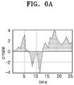
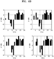
- FIG. 6A illustrates a continuous charge and discharge according to a comparative example
- FIG. 6B illustrates a continuous charge and discharge according to one embodiment.
- Continuous charge and discharge may correspond to a system using a plurality of batteries, like an energy storage apparatus, where continuous charging or discharging currents having the same pattern are applied to all of the plurality of batteries when charging or discharging the batteries (or battery packs).
- the charging and discharging method corresponding to the comparative example may cause a problem where the degradation of a battery is accelerated when a high-rate charging current is applied to the battery to improve charging speed.
- the continuous charge and discharge performed in FIG. 6B uses a pulse charge and discharge and may be illustrated by four pulse graphs as obtained by dividing the graph of FIG. 6A .
- the four graphs of FIG. 6B show results obtained when charging and discharging four battery packs.
- the graph on the upper left side is a graph for a first battery pack
- the graph on the upper right side is a graph for a second battery pack
- the graph on the lower right side is a graph for a third battery pack
- the graph on the lower left side is a graph for a fourth battery pack
- a charging current or a discharging current that is discontinuous according to time is applied to the first through fourth battery packs.
- the C-rate does not exceed 4C during a pulse charge and discharge.
- a range of the C-rate was set so as to reduce or minimize deterioration of batteries according to characteristics of the first through fourth battery packs.
- deterioration characteristics of a battery may vary according to the size of the C-rate, which therefore may adversely influence the lifetime of the battery. Accordingly, the C-rate may be determined to be in a range that does not have an adverse influence on the deterioration characteristics of the battery and a battery pack may be charged and discharged with the C-rate in this range.
- the charge and discharge controller 140 may charge or discharge the second battery pack during a pulse-off time of a pulse charge and discharge operation of the first battery pack. This is for giving a rest time to a battery pack, and a deterioration speed of the battery pack may be lowered by giving the rest time to the battery pack.
- the charge and discharge controller 140 may charge or discharge the fourth battery pack during a pulse-off time of a pulse charge and discharge operation of the first through third battery packs while pulse-charging and discharging the first through fourth battery packs.
- the number of battery packs presented in the current specification, is only an example and may be flexibly adjusted according to an output capacity for a system and the size of an output voltage for the system.
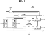
- FIG. 7 illustrates another embodiment of a battery charge and discharge control system 100' which includes a first battery pack 110, a second battery pack 120, an SOC measuring unit 130, a charge and discharge controller 140, and a state-of-health (SOH) calculator 150.
- the first battery pack 110, the second battery pack 120, the SOC measuring unit 130, and the charge and discharge controller 140 in FIG. 7 may be substantially the same as those in FIG. 1 .
- the SOH calculator 150 calculates a SOH of each of the first and second battery packs 110 and 120.
- the SOH may correspond to a performance index obtained, for example, by comparing an ideal state of a battery with a current state of the battery.
- SOH may be indicated in terms of a percentage (%), with an SOH of 100% denoting that the current state of a battery exactly satisfies one or more initial specifications of the battery.
- the SOH may be calculated in various ways. Examples include calculating SOH based on an internal resistance, impedance, capacity, voltages, and the number of charge and discharge operations of a battery.
- the SOH calculator 150 may periodically calculate the SOH of each of the first and second battery packs 110 and 120.
- the charge and discharge controller 140 may adjust the SOHs of the first and second battery packs 110 and 120 according to the calculated SOHs.
- the charge and discharge controller 140 may adjust the SOHs of the first and second battery packs 110 and 120 only when an SOH difference between the first battery pack 110 and the second battery pack 120 is equal to or greater than a third threshold value.
- the charge and discharge controller 140 adjusts the SOC of a battery pack. For example, when the SOCs of the first and second battery packs 110 and 120 are set to 40% and 60%, respectively, by adjustment of the charge and discharge controller 140 and lifetime characteristics of batteries are relatively better at SOC 40%, the SOH of the second battery pack 120 is lower than that of the first battery pack 120.
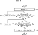
- FIG. 8 illustrates another embodiment of a battery charge and discharge control method for controlling charge and discharge operations of first and second battery packs which are connected in parallel.
- the method includes an SOC measuring operation S110, an SOC expanding operation S120, an SOC reducing operation S130, and a battery charging and discharging operation S140.
- SOCs of the first and second battery packs are adjusted so that the SOC difference between the first battery pack and the second battery pack equals the first threshold value.
- the first and second battery packs are pulse-charged with a first C-rate.
- the SOCs of the first and second battery packs may be adjusted, for example, so that an average of the SOCs of the first and second battery packs before the adjustment is equal to an average of the SOCs of the first and second battery packs after the adjustment.
- the SOC of the other battery pack is increased based on the amount of SOC increase of the first battery pack, or vice versa.
- the SOCs of the first and second battery packs may be adjusted so that the sum of a difference between the SOC of the first battery pack after the adjustment and a first reference value and a difference between the SOC of the second battery pack after the adjustment and the first reference value is increased or maximized.
- the first reference value may be an SOC value for reducing or minimizing lifetimes of the first and second battery packs.
- the first reference value may be 50%.
- the SOC of the first battery pack and the SOC of the second battery pack may be adjusted to be different or distant from 50%.
- the SOCs of the first and second battery packs may be adjusted within a range, in which the average of the SOCs of the first and second battery packs after the adjustment is equal to the average of the SOCs of the first and second battery packs before the adjustment, and an SOC range, in which an SOC difference between the first battery pack and the second battery pack is equal to the first threshold value.
- the SOCs of the first and second battery packs 110 and 120 may not be adjusted when the SOCs of the first and second battery packs are equal to or less than 10% or equal to or greater than 90% before adjusting the SOCs. Accordingly, even if the SOC difference between the first battery pack and the second battery pack is equal to or less than the first threshold value or is equal to or greater than the second threshold value, the SOCs of the first and second battery packs are not adjusted when the SOC of one of the first or second battery packs is equal to or less than 10% or is equal to or greater than 90%.
- the range, in which the SOC of one of the first or second battery packs may not be adjusted may be changed, for example, based on the number of batteries connected in parallel.
- the first C-rate in the battery charging and discharging operation S140 may be set based on a C-rate value for which the lifetimes of the first and second battery packs are increased or maximized. As described with reference to FIG. 5A , in a battery pack having best lifetime characteristics when the first C-rate is 3C, the first C-rate may be set to a value equal to or less than 4C or is close to 3C.
- a rest time may be given to each battery pack by charging and discharging the second battery pack during a pulse-off time of a pulse charge and discharge operation of the first battery pack. Lifetime characteristics of each battery pack may be improved by giving the rest time to each battery pack.
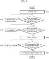
- FIG. 9 illustrates another embodiment of a battery charge and discharge control method which includes an SOC measuring operation S210, an SOC expanding operation S220, an SOC reducing operation S230, an SOH calculating operation S240, and a battery charging and discharging operation S250.
- the SOC measuring operation S210, the SOC expanding operation S220, the SOC reducing operation S230, and the battery charging and discharging operation S250 may be substantially the same as the SOC measuring operation S110, the SOC expanding operation S120, the SOC reducing operation S130, and the battery charging and discharging operation S140 in FIG. 8 .
- the SOCs of the first and second battery packs may be adjusted based on the SOHs of the first and second battery packs, calculated in operation S240.
- the SOH may be used as an index for determining a current lifetime state of a battery. When the SOH is high, the current state of the battery may be most similar to a state before the battery is used. Accordingly, it may be understood that, when the SOH is low, the battery further deteriorated.
- the SOC of a battery pack having a low SOH may be adjusted so that the battery pack operates in an SOC section other than an SOC section in which the battery pack currently operates.
- the SOCs of the first and second battery packs are set to 40% and 60%, respectively, by the adjustment in operation S220 or operation S230, and lifetime characteristics of batteries are relatively better at SOC 40%, the SOH of the second battery pack is lower than that of the first battery pack.
- the SOC of the first battery pack and the SOC of the second battery pack may be adjusted to 60% and 40%, respectively, in operation S250.
- deterioration priorities may be given to a plurality of battery packs, and the SOC of the battery pack may be adjusted only when an SOH of a battery pack having a relatively high priority is low.
- an apparatus in accordance with another embodiment, includes an interface and a controller to generate signals for output through the interface.
- the signals adjust a state-of-health (SOC) of each of a first battery pack and a second battery pack.
- SOC state-of-health
- the controller is to adjust the SOCs of the first and second battery packs so that the difference between the SOC of the first and second battery packs is equal to the first threshold value, an average of the SOCs of the first and second battery packs before the adjustment is equal to an average of the SOCs of the first and second battery packs after the adjustment.
- the interface may be may take various forms.
- the interface may be one or more output terminals, leads, wires, ports, signal lines, or other type of interface without or coupled to the controller.
- the methods, processes, and/or operations described herein may be performed by code or instructions to be executed by a computer, processor, controller, or other signal processing device.
- the computer, processor, controller, or other signal processing device may be those described herein or one in addition to the elements described herein. Because the algorithms that form the basis of the methods (or operations of the computer, processor, controller, or other signal processing device) are described in detail, the code or instructions for implementing the operations of the method embodiments may transform the computer, processor, controller, or other signal processing device into a special-purpose processor for performing the methods described herein.
- controllers, adjusters, measurers, and other processing features of the embodiments disclosed herein may be implemented in logic which, for example, may include hardware, software, or both.
- controllers, adjusters, measurers, and other processing features may be, for example, any one of a variety of integrated circuits including but not limited to an application-specific integrated circuit, a field-programmable gate array, a combination of logic gates, a system-on-chip, a microprocessor, or another type of processing or control circuit.
- the controllers, adjusters, measurers, and other processing features may include, for example, a memory or other storage device for storing code or instructions to be executed, for example, by a computer, processor, microprocessor, controller, or other signal processing device.
- the computer, processor, microprocessor, controller, or other signal processing device may be those described herein or one in addition to the elements described herein. Because the algorithms that form the basis of the methods (or operations of the computer, processor, microprocessor, controller, or other signal processing device) are described in detail, the code or instructions for implementing the operations of the method embodiments may transform the computer, processor, controller, or other signal processing device into a special-purpose processor for performing the methods described herein.
- another embodiment may include a computer-readable medium, e.g., a non-transitory computer-readable medium, for storing the code or instructions described above.
- the computer-readable medium may be a volatile or non-volatile memory or other storage device, which may be removably or fixedly coupled to the computer, processor, controller, or other signal processing device which is to execute the code or instructions for performing the method embodiments described herein.
- a battery charge and discharge control system comprises first and second battery packs connected in parallel; a state-of-charge (SOC) measurer to measure charge states of the first and second battery packs; and a controller.
- the controller is to adjust SOCs of the first and second battery packs.
- SOC state-of-charge
- the controller is to adjust the SOCs of the first and second battery packs so that the difference between the SOC of the first battery pack and the SOC of the second battery pack is equal to the first threshold value, and an average of the SOCs of the first and second battery packs before the adjustment is equal to an average of the SOCs of the first and second battery packs after the adjustment.
- the controller is to pulse-charge or pulse-discharge the first and second battery packs with a first C-rate.
- the controller may be configured to adjust the SOCs of the first and second battery packs so that a sum of a difference between the SOC of the first battery pack after the adjustment and a first reference value and a difference between the SOC of the second battery pack after the adjustment and the first reference value is increased, the first reference value corresponding to an SOC value for reducing lifetimes of the first and second battery packs.
- the controller may not to adjust the SOCs of the first and second battery packs when the SOCs of the first and second battery packs are equal to or less than 10% or equal to or greater than 90% before adjusting the SOCs.
- the controller may be configured to charge or discharge the second battery pack during a pulse-off time of a pulse charge and discharge operation of the first battery pack.
- a method comprises, for controlling first and second battery packs connected in parallel, (a) measuring charge states (SOC) of the first and second battery packs; (b) adjusting the SOCs of the first and second battery packs so that when a difference between the SOC of the first battery pack and the SOC of the second battery pack is equal to or less than a first threshold value, the difference between the SOC of the first battery pack and the SOC of the second battery pack are equal to the first threshold value;(c) adjusting the SOCs of the first and second battery packs so that when the difference between the SOC of the first battery pack and the SOC of the second battery pack is equal to or greater than a second threshold value, the difference between the SOC of the first battery pack and the SOC of the second battery pack is equal to the second threshold value; and (d) pulse-charging the first and second battery packs with a first C-rate.
- SOC charge states
- Step (b) may include adjusting the SOCs of the first and second battery packs so that a sum of a difference between the SOC of the first battery pack after the adjustment of the SOCs and a first reference value and a difference between the SOC of the second battery pack after the adjustment of the SOCs and the first reference value is increased or maximized, the first reference value corresponding to an SOC value for reducing or minimizing lifetimes of the first and second battery packs.
Landscapes
- Engineering & Computer Science (AREA)
- Power Engineering (AREA)
- Life Sciences & Earth Sciences (AREA)
- Sustainable Development (AREA)
- Sustainable Energy (AREA)
- Transportation (AREA)
- Mechanical Engineering (AREA)
- Health & Medical Sciences (AREA)
- General Health & Medical Sciences (AREA)
- Medical Informatics (AREA)
- Chemical & Material Sciences (AREA)
- Chemical Kinetics & Catalysis (AREA)
- Electrochemistry (AREA)
- General Chemical & Material Sciences (AREA)
- Manufacturing & Machinery (AREA)
- Charge And Discharge Circuits For Batteries Or The Like (AREA)
- Secondary Cells (AREA)
Applications Claiming Priority (1)
| Application Number | Priority Date | Filing Date | Title |
|---|---|---|---|
| KR1020150015594A KR102256301B1 (ko) | 2015-01-30 | 2015-01-30 | 배터리 충방전 제어 시스템 및 방법 |
Publications (2)
| Publication Number | Publication Date |
|---|---|
| EP3051657A1 EP3051657A1 (en) | 2016-08-03 |
| EP3051657B1 true EP3051657B1 (en) | 2017-10-11 |
Family
ID=55274990
Family Applications (1)
| Application Number | Title | Priority Date | Filing Date |
|---|---|---|---|
| EP16153361.7A Active EP3051657B1 (en) | 2015-01-30 | 2016-01-29 | Battery charge and discharge control system and battery charge and discharge control method |
Country Status (4)
| Country | Link |
|---|---|
| US (1) | US9800064B2 (ko) |
| EP (1) | EP3051657B1 (ko) |
| KR (1) | KR102256301B1 (ko) |
| CN (1) | CN105846489B (ko) |
Cited By (1)
| Publication number | Priority date | Publication date | Assignee | Title |
|---|---|---|---|---|
| CN110329110A (zh) * | 2019-08-06 | 2019-10-15 | 江西博能上饶客车有限公司 | 一种用于电动客车的电池安全控制系统和控制方法 |
Families Citing this family (23)
| Publication number | Priority date | Publication date | Assignee | Title |
|---|---|---|---|---|
| EP3197006B1 (en) * | 2016-01-21 | 2021-06-16 | Samsung Electronics Co., Ltd. | Apparatus and method of charging battery pack |
| CN107769279B (zh) * | 2016-08-18 | 2020-11-17 | 太普动力新能源(常熟)股份有限公司 | 电池并联搭接的控制方法 |
| MX2019003016A (es) * | 2016-09-15 | 2019-09-27 | Nantenergy Inc | Sistema de baterías hibridas. |
| CN106340689A (zh) * | 2016-11-21 | 2017-01-18 | 上海航天电源技术有限责任公司 | 一种电池组系统容量自学习的方法 |
| EP3567693A4 (en) * | 2017-01-05 | 2020-07-01 | Sony Interactive Entertainment Inc. | ELECTRICAL DEVICE |
| CN106887086B (zh) * | 2017-04-07 | 2022-10-21 | 上海蔚来汽车有限公司 | 移动充电设备、移动充电系统及移动充电方法 |
| KR102441469B1 (ko) * | 2017-11-13 | 2022-09-06 | 주식회사 엘지에너지솔루션 | 배터리 충전 방법 및 배터리 충전 장치 |
| KR102525676B1 (ko) * | 2018-02-20 | 2023-04-24 | 에스케이온 주식회사 | 배터리 관리 시스템 |
| AU2018416067A1 (en) * | 2018-03-26 | 2020-10-15 | Kabushiki Kaisha Toshiba | Power storage control device, power storage system and control method |
| KR102361334B1 (ko) * | 2018-05-09 | 2022-02-09 | 주식회사 엘지에너지솔루션 | 배터리 제어 장치 및 이를 포함하는 에너지 저장 시스템 |
| CN108819747B (zh) * | 2018-06-13 | 2021-11-02 | 蔚来(安徽)控股有限公司 | 多支路储能系统的多支路功率分配管理 |
| CN110970949A (zh) * | 2018-09-29 | 2020-04-07 | Oppo广东移动通信有限公司 | 充电控制方法、装置、存储介质及分体式电子设备 |
| JP7070332B2 (ja) * | 2018-10-29 | 2022-05-18 | トヨタ自動車株式会社 | 電動車両 |
| CN111313490B (zh) * | 2018-12-12 | 2023-05-12 | 湖南中车时代电动汽车股份有限公司 | 一种电池堆的充放电方法、装置、介质及系统 |
| KR102594315B1 (ko) | 2019-03-05 | 2023-10-27 | 현대자동차주식회사 | 차량 및 그 제어 방법 |
| CN110212607B (zh) * | 2019-06-14 | 2023-03-14 | Oppo广东移动通信有限公司 | 充电控制方法及相关产品 |
| KR20210016795A (ko) * | 2019-08-05 | 2021-02-17 | 주식회사 엘지화학 | 에너지 허브 장치 및 에너지 관리 방법 |
| CN110474395A (zh) * | 2019-08-27 | 2019-11-19 | 常州格力博有限公司 | 电力系统 |
| CN110780209B (zh) * | 2019-11-27 | 2021-12-17 | 深圳市科陆电子科技股份有限公司 | Bms电池容量标定方法 |
| GB201918939D0 (en) * | 2019-12-20 | 2020-02-05 | Delta Motorsport Ltd | Power routing system |
| US11070080B1 (en) * | 2020-04-03 | 2021-07-20 | Cattron North America, Inc. | Reserve power supply system |
| US11777330B2 (en) * | 2020-07-22 | 2023-10-03 | Microsoft Technology Licensing, Llc | Common charge controller for electronic devices with multiple batteries |
| CN114030388B (zh) * | 2021-10-27 | 2024-02-27 | 智新控制系统有限公司 | 过流保护系统及方法 |
Family Cites Families (19)
| Publication number | Priority date | Publication date | Assignee | Title |
|---|---|---|---|---|
| JPH1197074A (ja) * | 1997-09-19 | 1999-04-09 | Zip Charge:Kk | 充電方法及び充電装置 |
| US6232744B1 (en) * | 1999-02-24 | 2001-05-15 | Denso Corporation | Method of controlling battery condition of self-generation electric vehicle |
| JP3997965B2 (ja) * | 2003-07-29 | 2007-10-24 | トヨタ自動車株式会社 | 組電池の充放電制御装置および方法、プログラム、電池制御システム |
| SG120181A1 (en) * | 2004-08-18 | 2006-03-28 | Gp Batteries Internat Ltd | Method and system for determining the SOC of a rechargeable battery |
| KR100698355B1 (ko) | 2005-02-02 | 2007-03-23 | 이동호 | 여러 개의 배터리에 교대로 펄스충전하는 독립형태양광(풍력)발전용 충방전제어시스템 |
| JP4527048B2 (ja) * | 2005-12-02 | 2010-08-18 | パナソニックEvエナジー株式会社 | 二次電池用の制御装置及び二次電池の入力制御方法 |
| JP4527047B2 (ja) * | 2005-12-02 | 2010-08-18 | パナソニックEvエナジー株式会社 | 二次電池用の制御装置及び二次電池の出力制御方法 |
| KR101264427B1 (ko) * | 2006-07-31 | 2013-05-14 | 삼성에스디아이 주식회사 | 하이브리드 배터리 팩 및 그것의 충전 방법 |
| KR20090014898A (ko) | 2007-08-07 | 2009-02-11 | 엘지전자 주식회사 | 배터리팩과 이의 충방전제어방법 |
| US8049465B2 (en) * | 2007-10-10 | 2011-11-01 | Texas Instruments Incorporated | Systems, methods and circuits for determining micro-short |
| JP2011015473A (ja) * | 2009-06-30 | 2011-01-20 | Toyota Motor Corp | 電源システムおよびそれを備えた電動車両ならびに電源システムの制御方法 |
| KR20110024707A (ko) * | 2009-09-03 | 2011-03-09 | 주식회사 엘지화학 | 리튬 이차 전지의 충전 방법 |
| CN101777784A (zh) * | 2010-03-17 | 2010-07-14 | 北汽福田汽车股份有限公司 | 均衡充电装置及均衡充电方法 |
| US8866444B2 (en) * | 2010-06-08 | 2014-10-21 | Tesla Motors, Inc. | Methodology for charging batteries safely |
| EP2838176B1 (en) | 2012-06-07 | 2017-06-07 | Lg Chem, Ltd. | Method for charging secondary battery |
| CN102868000B (zh) * | 2012-09-05 | 2015-06-17 | 浙江众泰新能源汽车科技有限公司 | 一种电动汽车动力源均衡方法 |
| JP2014147197A (ja) * | 2013-01-29 | 2014-08-14 | Hitachi Automotive Systems Ltd | バッテリ制御装置 |
| KR101987484B1 (ko) | 2013-06-11 | 2019-06-10 | 현대자동차주식회사 | 배터리 충방전 제어장치 및 제어방법 |
| KR101497549B1 (ko) * | 2013-06-27 | 2015-03-02 | 강원도 | 배터리의 충전용량 복원방법 및 이를 위한 충전장치 |
-
2015
- 2015-01-30 KR KR1020150015594A patent/KR102256301B1/ko active IP Right Grant
- 2015-08-31 US US14/840,295 patent/US9800064B2/en active Active
-
2016
- 2016-01-29 EP EP16153361.7A patent/EP3051657B1/en active Active
- 2016-02-01 CN CN201610069453.9A patent/CN105846489B/zh active Active
Non-Patent Citations (1)
| Title |
|---|
| None * |
Cited By (2)
| Publication number | Priority date | Publication date | Assignee | Title |
|---|---|---|---|---|
| CN110329110A (zh) * | 2019-08-06 | 2019-10-15 | 江西博能上饶客车有限公司 | 一种用于电动客车的电池安全控制系统和控制方法 |
| CN110329110B (zh) * | 2019-08-06 | 2020-12-04 | 江西博能上饶客车有限公司 | 一种用于电动客车的电池安全控制系统和控制方法 |
Also Published As
| Publication number | Publication date |
|---|---|
| CN105846489A (zh) | 2016-08-10 |
| CN105846489B (zh) | 2020-10-20 |
| EP3051657A1 (en) | 2016-08-03 |
| KR20160094229A (ko) | 2016-08-09 |
| US20160226269A1 (en) | 2016-08-04 |
| KR102256301B1 (ko) | 2021-05-26 |
| US9800064B2 (en) | 2017-10-24 |
Similar Documents
| Publication | Publication Date | Title |
|---|---|---|
| EP3051657B1 (en) | Battery charge and discharge control system and battery charge and discharge control method | |
| JP6295858B2 (ja) | バッテリ管理装置 | |
| EP3064952B1 (en) | Energy storage device management apparatus, energy storage device management method, energy storage device module, energy storage device management program, and movable body | |
| JP7119262B2 (ja) | バッテリー管理装置 | |
| JP2020511737A (ja) | バッテリーの内部抵抗を最適化するためのバッテリー管理システム及び方法 | |
| JP7169497B2 (ja) | バッテリー管理装置 | |
| US10222425B2 (en) | Battery control IC and control method therefore | |
| JP7054868B2 (ja) | 電池管理装置、電池システム、及び車両用電源システム | |
| JP7293566B2 (ja) | バッテリー退化度診断装置及び方法 | |
| EP3796015B1 (en) | State-of-charge correction method and device | |
| EP4231025A1 (en) | Method and apparatus for determining remaining charging time, and vehicle | |
| US10845419B2 (en) | Assembled battery circuit, capacitance coefficient detection method, and capacitance coefficient detection program | |
| US20160013521A1 (en) | Storage battery, control method of storage battery, control device, and control method | |
| JP6155743B2 (ja) | 充電状態検出装置および充電状態検出方法 | |
| JP2018129958A (ja) | 充電率均等化装置 | |
| JPWO2019220805A1 (ja) | 管理装置、蓄電システム | |
| CN111682269B (zh) | 二次电池系统、二次电池和组装电池系统 | |
| JP2017169366A (ja) | 電池装置、セルバランス装置およびセルバランス方法 | |
| US20220003822A1 (en) | Battery control device | |
| CN108572323B (zh) | 电池状态推测装置 | |
| JP5966998B2 (ja) | 充電装置及び充電方法 | |
| WO2015162259A1 (en) | Continuous evaluation of health parameters for higher safety in battery operation | |
| US20150229142A1 (en) | Battery control device, electric storage device, method for operating electric storage device, and program | |
| JP4300363B2 (ja) | 組電池容量調整装置及び方法 | |
| JP7169917B2 (ja) | 二次電池の制御装置及び二次電池の制御方法 |
Legal Events
| Date | Code | Title | Description |
|---|---|---|---|
| PUAI | Public reference made under article 153(3) epc to a published international application that has entered the european phase |
Free format text: ORIGINAL CODE: 0009012 |
|
| AK | Designated contracting states |
Kind code of ref document: A1 Designated state(s): AL AT BE BG CH CY CZ DE DK EE ES FI FR GB GR HR HU IE IS IT LI LT LU LV MC MK MT NL NO PL PT RO RS SE SI SK SM TR |
|
| AX | Request for extension of the european patent |
Extension state: BA ME |
|
| 17P | Request for examination filed |
Effective date: 20161129 |
|
| RBV | Designated contracting states (corrected) |
Designated state(s): AL AT BE BG CH CY CZ DE DK EE ES FI FR GB GR HR HU IE IS IT LI LT LU LV MC MK MT NL NO PL PT RO RS SE SI SK SM TR |
|
| RIC1 | Information provided on ipc code assigned before grant |
Ipc: H02J 7/34 20060101ALN20170420BHEP Ipc: H02J 7/00 20060101AFI20170420BHEP Ipc: B60L 3/00 20060101ALI20170420BHEP Ipc: B60L 11/18 20060101ALN20170420BHEP |
|
| GRAP | Despatch of communication of intention to grant a patent |
Free format text: ORIGINAL CODE: EPIDOSNIGR1 |
|
| INTG | Intention to grant announced |
Effective date: 20170526 |
|
| RIC1 | Information provided on ipc code assigned before grant |
Ipc: H02J 7/34 20060101ALN20170512BHEP Ipc: B60L 3/00 20060101ALI20170512BHEP Ipc: B60L 11/18 20060101ALN20170512BHEP Ipc: H02J 7/00 20060101AFI20170512BHEP |
|
| GRAS | Grant fee paid |
Free format text: ORIGINAL CODE: EPIDOSNIGR3 |
|
| GRAA | (expected) grant |
Free format text: ORIGINAL CODE: 0009210 |
|
| AK | Designated contracting states |
Kind code of ref document: B1 Designated state(s): AL AT BE BG CH CY CZ DE DK EE ES FI FR GB GR HR HU IE IS IT LI LT LU LV MC MK MT NL NO PL PT RO RS SE SI SK SM TR |
|
| REG | Reference to a national code |
Ref country code: GB Ref legal event code: FG4D |
|
| REG | Reference to a national code |
Ref country code: CH Ref legal event code: EP |
|
| REG | Reference to a national code |
Ref country code: IE Ref legal event code: FG4D |
|
| REG | Reference to a national code |
Ref country code: AT Ref legal event code: REF Ref document number: 936825 Country of ref document: AT Kind code of ref document: T Effective date: 20171115 |
|
| REG | Reference to a national code |
Ref country code: DE Ref legal event code: R096 Ref document number: 602016000521 Country of ref document: DE |
|
| REG | Reference to a national code |
Ref country code: FR Ref legal event code: PLFP Year of fee payment: 3 |
|
| REG | Reference to a national code |
Ref country code: NL Ref legal event code: MP Effective date: 20171011 |
|
| REG | Reference to a national code |
Ref country code: LT Ref legal event code: MG4D |
|
| REG | Reference to a national code |
Ref country code: AT Ref legal event code: MK05 Ref document number: 936825 Country of ref document: AT Kind code of ref document: T Effective date: 20171011 |
|
| PG25 | Lapsed in a contracting state [announced via postgrant information from national office to epo] |
Ref country code: NL Free format text: LAPSE BECAUSE OF FAILURE TO SUBMIT A TRANSLATION OF THE DESCRIPTION OR TO PAY THE FEE WITHIN THE PRESCRIBED TIME-LIMIT Effective date: 20171011 |
|
| PG25 | Lapsed in a contracting state [announced via postgrant information from national office to epo] |
Ref country code: LT Free format text: LAPSE BECAUSE OF FAILURE TO SUBMIT A TRANSLATION OF THE DESCRIPTION OR TO PAY THE FEE WITHIN THE PRESCRIBED TIME-LIMIT Effective date: 20171011 Ref country code: ES Free format text: LAPSE BECAUSE OF FAILURE TO SUBMIT A TRANSLATION OF THE DESCRIPTION OR TO PAY THE FEE WITHIN THE PRESCRIBED TIME-LIMIT Effective date: 20171011 Ref country code: SE Free format text: LAPSE BECAUSE OF FAILURE TO SUBMIT A TRANSLATION OF THE DESCRIPTION OR TO PAY THE FEE WITHIN THE PRESCRIBED TIME-LIMIT Effective date: 20171011 Ref country code: NO Free format text: LAPSE BECAUSE OF FAILURE TO SUBMIT A TRANSLATION OF THE DESCRIPTION OR TO PAY THE FEE WITHIN THE PRESCRIBED TIME-LIMIT Effective date: 20180111 Ref country code: FI Free format text: LAPSE BECAUSE OF FAILURE TO SUBMIT A TRANSLATION OF THE DESCRIPTION OR TO PAY THE FEE WITHIN THE PRESCRIBED TIME-LIMIT Effective date: 20171011 |
|
| PG25 | Lapsed in a contracting state [announced via postgrant information from national office to epo] |
Ref country code: RS Free format text: LAPSE BECAUSE OF FAILURE TO SUBMIT A TRANSLATION OF THE DESCRIPTION OR TO PAY THE FEE WITHIN THE PRESCRIBED TIME-LIMIT Effective date: 20171011 Ref country code: AT Free format text: LAPSE BECAUSE OF FAILURE TO SUBMIT A TRANSLATION OF THE DESCRIPTION OR TO PAY THE FEE WITHIN THE PRESCRIBED TIME-LIMIT Effective date: 20171011 Ref country code: BG Free format text: LAPSE BECAUSE OF FAILURE TO SUBMIT A TRANSLATION OF THE DESCRIPTION OR TO PAY THE FEE WITHIN THE PRESCRIBED TIME-LIMIT Effective date: 20180111 Ref country code: LV Free format text: LAPSE BECAUSE OF FAILURE TO SUBMIT A TRANSLATION OF THE DESCRIPTION OR TO PAY THE FEE WITHIN THE PRESCRIBED TIME-LIMIT Effective date: 20171011 Ref country code: IS Free format text: LAPSE BECAUSE OF FAILURE TO SUBMIT A TRANSLATION OF THE DESCRIPTION OR TO PAY THE FEE WITHIN THE PRESCRIBED TIME-LIMIT Effective date: 20180211 Ref country code: HR Free format text: LAPSE BECAUSE OF FAILURE TO SUBMIT A TRANSLATION OF THE DESCRIPTION OR TO PAY THE FEE WITHIN THE PRESCRIBED TIME-LIMIT Effective date: 20171011 Ref country code: GR Free format text: LAPSE BECAUSE OF FAILURE TO SUBMIT A TRANSLATION OF THE DESCRIPTION OR TO PAY THE FEE WITHIN THE PRESCRIBED TIME-LIMIT Effective date: 20180112 |
|
| REG | Reference to a national code |
Ref country code: DE Ref legal event code: R097 Ref document number: 602016000521 Country of ref document: DE |
|
| PG25 | Lapsed in a contracting state [announced via postgrant information from national office to epo] |
Ref country code: EE Free format text: LAPSE BECAUSE OF FAILURE TO SUBMIT A TRANSLATION OF THE DESCRIPTION OR TO PAY THE FEE WITHIN THE PRESCRIBED TIME-LIMIT Effective date: 20171011 Ref country code: CZ Free format text: LAPSE BECAUSE OF FAILURE TO SUBMIT A TRANSLATION OF THE DESCRIPTION OR TO PAY THE FEE WITHIN THE PRESCRIBED TIME-LIMIT Effective date: 20171011 Ref country code: SK Free format text: LAPSE BECAUSE OF FAILURE TO SUBMIT A TRANSLATION OF THE DESCRIPTION OR TO PAY THE FEE WITHIN THE PRESCRIBED TIME-LIMIT Effective date: 20171011 Ref country code: DK Free format text: LAPSE BECAUSE OF FAILURE TO SUBMIT A TRANSLATION OF THE DESCRIPTION OR TO PAY THE FEE WITHIN THE PRESCRIBED TIME-LIMIT Effective date: 20171011 |
|
| PLBE | No opposition filed within time limit |
Free format text: ORIGINAL CODE: 0009261 |
|
| STAA | Information on the status of an ep patent application or granted ep patent |
Free format text: STATUS: NO OPPOSITION FILED WITHIN TIME LIMIT |
|
| PG25 | Lapsed in a contracting state [announced via postgrant information from national office to epo] |
Ref country code: PL Free format text: LAPSE BECAUSE OF FAILURE TO SUBMIT A TRANSLATION OF THE DESCRIPTION OR TO PAY THE FEE WITHIN THE PRESCRIBED TIME-LIMIT Effective date: 20171011 Ref country code: IT Free format text: LAPSE BECAUSE OF FAILURE TO SUBMIT A TRANSLATION OF THE DESCRIPTION OR TO PAY THE FEE WITHIN THE PRESCRIBED TIME-LIMIT Effective date: 20171011 Ref country code: RO Free format text: LAPSE BECAUSE OF FAILURE TO SUBMIT A TRANSLATION OF THE DESCRIPTION OR TO PAY THE FEE WITHIN THE PRESCRIBED TIME-LIMIT Effective date: 20171011 Ref country code: SM Free format text: LAPSE BECAUSE OF FAILURE TO SUBMIT A TRANSLATION OF THE DESCRIPTION OR TO PAY THE FEE WITHIN THE PRESCRIBED TIME-LIMIT Effective date: 20171011 |
|
| 26N | No opposition filed |
Effective date: 20180712 |
|
| PG25 | Lapsed in a contracting state [announced via postgrant information from national office to epo] |
Ref country code: LU Free format text: LAPSE BECAUSE OF NON-PAYMENT OF DUE FEES Effective date: 20180129 |
|
| REG | Reference to a national code |
Ref country code: IE Ref legal event code: MM4A |
|
| REG | Reference to a national code |
Ref country code: BE Ref legal event code: MM Effective date: 20180131 |
|
| PG25 | Lapsed in a contracting state [announced via postgrant information from national office to epo] |
Ref country code: BE Free format text: LAPSE BECAUSE OF NON-PAYMENT OF DUE FEES Effective date: 20180131 Ref country code: SI Free format text: LAPSE BECAUSE OF FAILURE TO SUBMIT A TRANSLATION OF THE DESCRIPTION OR TO PAY THE FEE WITHIN THE PRESCRIBED TIME-LIMIT Effective date: 20171011 |
|
| PG25 | Lapsed in a contracting state [announced via postgrant information from national office to epo] |
Ref country code: IE Free format text: LAPSE BECAUSE OF NON-PAYMENT OF DUE FEES Effective date: 20180129 |
|
| PG25 | Lapsed in a contracting state [announced via postgrant information from national office to epo] |
Ref country code: MC Free format text: LAPSE BECAUSE OF FAILURE TO SUBMIT A TRANSLATION OF THE DESCRIPTION OR TO PAY THE FEE WITHIN THE PRESCRIBED TIME-LIMIT Effective date: 20171011 |
|
| REG | Reference to a national code |
Ref country code: CH Ref legal event code: PL |
|
| PG25 | Lapsed in a contracting state [announced via postgrant information from national office to epo] |
Ref country code: CH Free format text: LAPSE BECAUSE OF NON-PAYMENT OF DUE FEES Effective date: 20190131 Ref country code: LI Free format text: LAPSE BECAUSE OF NON-PAYMENT OF DUE FEES Effective date: 20190131 |
|
| PG25 | Lapsed in a contracting state [announced via postgrant information from national office to epo] |
Ref country code: MT Free format text: LAPSE BECAUSE OF NON-PAYMENT OF DUE FEES Effective date: 20180129 |
|
| PG25 | Lapsed in a contracting state [announced via postgrant information from national office to epo] |
Ref country code: TR Free format text: LAPSE BECAUSE OF FAILURE TO SUBMIT A TRANSLATION OF THE DESCRIPTION OR TO PAY THE FEE WITHIN THE PRESCRIBED TIME-LIMIT Effective date: 20171011 |
|
| PG25 | Lapsed in a contracting state [announced via postgrant information from national office to epo] |
Ref country code: PT Free format text: LAPSE BECAUSE OF FAILURE TO SUBMIT A TRANSLATION OF THE DESCRIPTION OR TO PAY THE FEE WITHIN THE PRESCRIBED TIME-LIMIT Effective date: 20171011 |
|
| PG25 | Lapsed in a contracting state [announced via postgrant information from national office to epo] |
Ref country code: HU Free format text: LAPSE BECAUSE OF FAILURE TO SUBMIT A TRANSLATION OF THE DESCRIPTION OR TO PAY THE FEE WITHIN THE PRESCRIBED TIME-LIMIT; INVALID AB INITIO Effective date: 20160129 Ref country code: CY Free format text: LAPSE BECAUSE OF FAILURE TO SUBMIT A TRANSLATION OF THE DESCRIPTION OR TO PAY THE FEE WITHIN THE PRESCRIBED TIME-LIMIT Effective date: 20171011 Ref country code: MK Free format text: LAPSE BECAUSE OF NON-PAYMENT OF DUE FEES Effective date: 20171011 |
|
| PG25 | Lapsed in a contracting state [announced via postgrant information from national office to epo] |
Ref country code: AL Free format text: LAPSE BECAUSE OF FAILURE TO SUBMIT A TRANSLATION OF THE DESCRIPTION OR TO PAY THE FEE WITHIN THE PRESCRIBED TIME-LIMIT Effective date: 20171011 |
|
| P01 | Opt-out of the competence of the unified patent court (upc) registered |
Effective date: 20230528 |
|
| PGFP | Annual fee paid to national office [announced via postgrant information from national office to epo] |
Ref country code: GB Payment date: 20231221 Year of fee payment: 9 |
|
| PGFP | Annual fee paid to national office [announced via postgrant information from national office to epo] |
Ref country code: FR Payment date: 20231222 Year of fee payment: 9 |
|
| PGFP | Annual fee paid to national office [announced via postgrant information from national office to epo] |
Ref country code: DE Payment date: 20231228 Year of fee payment: 9 |