EP3051611A1 - Élément de batterie comprenant des moyens de protection contre les courts-circuits - Google Patents
Élément de batterie comprenant des moyens de protection contre les courts-circuits Download PDFInfo
- Publication number
- EP3051611A1 EP3051611A1 EP14866202.6A EP14866202A EP3051611A1 EP 3051611 A1 EP3051611 A1 EP 3051611A1 EP 14866202 A EP14866202 A EP 14866202A EP 3051611 A1 EP3051611 A1 EP 3051611A1
- Authority
- EP
- European Patent Office
- Prior art keywords
- battery cell
- electrode assembly
- rubber
- battery
- cell according
- Prior art date
- Legal status (The legal status is an assumption and is not a legal conclusion. Google has not performed a legal analysis and makes no representation as to the accuracy of the status listed.)
- Granted
Links
- 239000000463 material Substances 0.000 claims abstract description 52
- 229910052751 metal Inorganic materials 0.000 claims description 34
- 239000002184 metal Substances 0.000 claims description 34
- 229920001971 elastomer Polymers 0.000 claims description 8
- 239000005060 rubber Substances 0.000 claims description 8
- 229920000459 Nitrile rubber Polymers 0.000 claims description 6
- 229920001084 poly(chloroprene) Polymers 0.000 claims description 6
- 239000003973 paint Substances 0.000 claims description 5
- 229920002943 EPDM rubber Polymers 0.000 claims description 4
- WHXSMMKQMYFTQS-UHFFFAOYSA-N Lithium Chemical compound [Li] WHXSMMKQMYFTQS-UHFFFAOYSA-N 0.000 claims description 4
- 229920005549 butyl rubber Polymers 0.000 claims description 4
- 229920003049 isoprene rubber Polymers 0.000 claims description 4
- 229910052744 lithium Inorganic materials 0.000 claims description 4
- 229920003048 styrene butadiene rubber Polymers 0.000 claims description 4
- 229920003051 synthetic elastomer Polymers 0.000 claims description 4
- 239000005061 synthetic rubber Substances 0.000 claims description 4
- 230000001413 cellular effect Effects 0.000 claims description 3
- 238000000926 separation method Methods 0.000 claims description 3
- 229920000181 Ethylene propylene rubber Polymers 0.000 claims description 2
- 244000043261 Hevea brasiliensis Species 0.000 claims description 2
- 239000005062 Polybutadiene Substances 0.000 claims description 2
- 229920006311 Urethane elastomer Polymers 0.000 claims description 2
- 229920000800 acrylic rubber Polymers 0.000 claims description 2
- 229920001973 fluoroelastomer Polymers 0.000 claims description 2
- 239000000203 mixture Substances 0.000 claims description 2
- 229920003052 natural elastomer Polymers 0.000 claims description 2
- 229920001194 natural rubber Polymers 0.000 claims description 2
- 229920000058 polyacrylate Polymers 0.000 claims description 2
- 229920002857 polybutadiene Polymers 0.000 claims description 2
- 239000005077 polysulfide Substances 0.000 claims description 2
- 229920001021 polysulfide Polymers 0.000 claims description 2
- 150000008117 polysulfides Polymers 0.000 claims description 2
- 239000011347 resin Substances 0.000 claims description 2
- 229920005989 resin Polymers 0.000 claims description 2
- 229920002379 silicone rubber Polymers 0.000 claims description 2
- 239000004945 silicone rubber Substances 0.000 claims description 2
- 230000000694 effects Effects 0.000 description 7
- 230000000052 comparative effect Effects 0.000 description 6
- HBBGRARXTFLTSG-UHFFFAOYSA-N Lithium ion Chemical compound [Li+] HBBGRARXTFLTSG-UHFFFAOYSA-N 0.000 description 4
- 229910001416 lithium ion Inorganic materials 0.000 description 4
- 230000000149 penetrating effect Effects 0.000 description 4
- 238000002485 combustion reaction Methods 0.000 description 3
- 238000010276 construction Methods 0.000 description 3
- 238000004519 manufacturing process Methods 0.000 description 3
- 238000011160 research Methods 0.000 description 3
- AZDRQVAHHNSJOQ-UHFFFAOYSA-N alumane Chemical class [AlH3] AZDRQVAHHNSJOQ-UHFFFAOYSA-N 0.000 description 2
- 239000003792 electrolyte Substances 0.000 description 2
- 238000012986 modification Methods 0.000 description 2
- 230000004048 modification Effects 0.000 description 2
- 229920000642 polymer Polymers 0.000 description 2
- 230000002265 prevention Effects 0.000 description 2
- 239000004809 Teflon Substances 0.000 description 1
- 229920006362 Teflon® Polymers 0.000 description 1
- 230000002159 abnormal effect Effects 0.000 description 1
- 238000007792 addition Methods 0.000 description 1
- 229910052782 aluminium Inorganic materials 0.000 description 1
- XAGFODPZIPBFFR-UHFFFAOYSA-N aluminium Chemical compound [Al] XAGFODPZIPBFFR-UHFFFAOYSA-N 0.000 description 1
- 239000000356 contaminant Substances 0.000 description 1
- 238000011982 device technology Methods 0.000 description 1
- 238000005516 engineering process Methods 0.000 description 1
- 238000003912 environmental pollution Methods 0.000 description 1
- 239000002803 fossil fuel Substances 0.000 description 1
- 238000009863 impact test Methods 0.000 description 1
- 150000002500 ions Chemical class 0.000 description 1
- 235000015110 jellies Nutrition 0.000 description 1
- 239000008274 jelly Substances 0.000 description 1
- 238000000034 method Methods 0.000 description 1
- 238000006467 substitution reaction Methods 0.000 description 1
Images

Classifications
-
- H—ELECTRICITY
- H01—ELECTRIC ELEMENTS
- H01M—PROCESSES OR MEANS, e.g. BATTERIES, FOR THE DIRECT CONVERSION OF CHEMICAL ENERGY INTO ELECTRICAL ENERGY
- H01M10/00—Secondary cells; Manufacture thereof
- H01M10/05—Accumulators with non-aqueous electrolyte
- H01M10/058—Construction or manufacture
- H01M10/0587—Construction or manufacture of accumulators having only wound construction elements, i.e. wound positive electrodes, wound negative electrodes and wound separators
-
- H—ELECTRICITY
- H01—ELECTRIC ELEMENTS
- H01M—PROCESSES OR MEANS, e.g. BATTERIES, FOR THE DIRECT CONVERSION OF CHEMICAL ENERGY INTO ELECTRICAL ENERGY
- H01M50/00—Constructional details or processes of manufacture of the non-active parts of electrochemical cells other than fuel cells, e.g. hybrid cells
- H01M50/10—Primary casings; Jackets or wrappings
- H01M50/102—Primary casings; Jackets or wrappings characterised by their shape or physical structure
- H01M50/105—Pouches or flexible bags
-
- H—ELECTRICITY
- H01—ELECTRIC ELEMENTS
- H01M—PROCESSES OR MEANS, e.g. BATTERIES, FOR THE DIRECT CONVERSION OF CHEMICAL ENERGY INTO ELECTRICAL ENERGY
- H01M50/00—Constructional details or processes of manufacture of the non-active parts of electrochemical cells other than fuel cells, e.g. hybrid cells
- H01M50/10—Primary casings; Jackets or wrappings
- H01M50/116—Primary casings; Jackets or wrappings characterised by the material
- H01M50/124—Primary casings; Jackets or wrappings characterised by the material having a layered structure
-
- H—ELECTRICITY
- H01—ELECTRIC ELEMENTS
- H01M—PROCESSES OR MEANS, e.g. BATTERIES, FOR THE DIRECT CONVERSION OF CHEMICAL ENERGY INTO ELECTRICAL ENERGY
- H01M50/00—Constructional details or processes of manufacture of the non-active parts of electrochemical cells other than fuel cells, e.g. hybrid cells
- H01M50/10—Primary casings; Jackets or wrappings
- H01M50/147—Lids or covers
-
- H—ELECTRICITY
- H01—ELECTRIC ELEMENTS
- H01M—PROCESSES OR MEANS, e.g. BATTERIES, FOR THE DIRECT CONVERSION OF CHEMICAL ENERGY INTO ELECTRICAL ENERGY
- H01M50/00—Constructional details or processes of manufacture of the non-active parts of electrochemical cells other than fuel cells, e.g. hybrid cells
- H01M50/50—Current conducting connections for cells or batteries
- H01M50/543—Terminals
- H01M50/547—Terminals characterised by the disposition of the terminals on the cells
-
- H—ELECTRICITY
- H01—ELECTRIC ELEMENTS
- H01M—PROCESSES OR MEANS, e.g. BATTERIES, FOR THE DIRECT CONVERSION OF CHEMICAL ENERGY INTO ELECTRICAL ENERGY
- H01M50/00—Constructional details or processes of manufacture of the non-active parts of electrochemical cells other than fuel cells, e.g. hybrid cells
- H01M50/50—Current conducting connections for cells or batteries
- H01M50/572—Means for preventing undesired use or discharge
- H01M50/584—Means for preventing undesired use or discharge for preventing incorrect connections inside or outside the batteries
- H01M50/586—Means for preventing undesired use or discharge for preventing incorrect connections inside or outside the batteries inside the batteries, e.g. incorrect connections of electrodes
-
- H—ELECTRICITY
- H01—ELECTRIC ELEMENTS
- H01M—PROCESSES OR MEANS, e.g. BATTERIES, FOR THE DIRECT CONVERSION OF CHEMICAL ENERGY INTO ELECTRICAL ENERGY
- H01M10/00—Secondary cells; Manufacture thereof
- H01M10/05—Accumulators with non-aqueous electrolyte
- H01M10/052—Li-accumulators
-
- H—ELECTRICITY
- H01—ELECTRIC ELEMENTS
- H01M—PROCESSES OR MEANS, e.g. BATTERIES, FOR THE DIRECT CONVERSION OF CHEMICAL ENERGY INTO ELECTRICAL ENERGY
- H01M10/00—Secondary cells; Manufacture thereof
- H01M10/05—Accumulators with non-aqueous electrolyte
- H01M10/052—Li-accumulators
- H01M10/0525—Rocking-chair batteries, i.e. batteries with lithium insertion or intercalation in both electrodes; Lithium-ion batteries
-
- H—ELECTRICITY
- H01—ELECTRIC ELEMENTS
- H01M—PROCESSES OR MEANS, e.g. BATTERIES, FOR THE DIRECT CONVERSION OF CHEMICAL ENERGY INTO ELECTRICAL ENERGY
- H01M2200/00—Safety devices for primary or secondary batteries
-
- Y—GENERAL TAGGING OF NEW TECHNOLOGICAL DEVELOPMENTS; GENERAL TAGGING OF CROSS-SECTIONAL TECHNOLOGIES SPANNING OVER SEVERAL SECTIONS OF THE IPC; TECHNICAL SUBJECTS COVERED BY FORMER USPC CROSS-REFERENCE ART COLLECTIONS [XRACs] AND DIGESTS
- Y02—TECHNOLOGIES OR APPLICATIONS FOR MITIGATION OR ADAPTATION AGAINST CLIMATE CHANGE
- Y02E—REDUCTION OF GREENHOUSE GAS [GHG] EMISSIONS, RELATED TO ENERGY GENERATION, TRANSMISSION OR DISTRIBUTION
- Y02E60/00—Enabling technologies; Technologies with a potential or indirect contribution to GHG emissions mitigation
- Y02E60/10—Energy storage using batteries
-
- Y—GENERAL TAGGING OF NEW TECHNOLOGICAL DEVELOPMENTS; GENERAL TAGGING OF CROSS-SECTIONAL TECHNOLOGIES SPANNING OVER SEVERAL SECTIONS OF THE IPC; TECHNICAL SUBJECTS COVERED BY FORMER USPC CROSS-REFERENCE ART COLLECTIONS [XRACs] AND DIGESTS
- Y02—TECHNOLOGIES OR APPLICATIONS FOR MITIGATION OR ADAPTATION AGAINST CLIMATE CHANGE
- Y02P—CLIMATE CHANGE MITIGATION TECHNOLOGIES IN THE PRODUCTION OR PROCESSING OF GOODS
- Y02P70/00—Climate change mitigation technologies in the production process for final industrial or consumer products
- Y02P70/50—Manufacturing or production processes characterised by the final manufactured product
Definitions
- the present invention relates to a battery cell having a means for preventing short-circuit.
- secondary batteries may be classified based on the shape of a battery case of each of the secondary batteries into a cylindrical battery configured to have a structure in which an electrode assembly is mounted in a cylindrical metal container, a prismatic battery configured to have a structure in which an electrode assembly is mounted in a prismatic metal container, and a pouch-shaped battery configured to have a structure in which an electrode assembly is mounted in a pouch-shaped case made of a laminated aluminum sheet.
- a pouch-shaped battery configured to have a structure in which such a stacked or stacked/folded type electrode assembly is mounted in a pouch-shaped battery case made of a laminated aluminum sheet because of low manufacturing costs, light weight, easy modification of the shape thereof, etc.
- the use of such a pouch-shaped battery has gradually increased.
- secondary batteries may be classified based on the structure of an electrode assembly, which has a structure in which a positive electrode and a negative electrode are stacked in a state in which a separator is interposed between the positive electrode and the negative electrode.
- the electrode assembly may be configured to have a jelly-roll (wound) type structure in which a long sheet type positive electrode and a long sheet type negative electrode are wound in a state in which a separator is disposed between the positive electrode and the negative electrode or a stacked type structure in which pluralities of positive electrodes and negative electrodes each having a predetermined size are sequentially stacked in a state in which separators are disposed respectively between the positive electrodes and the negative electrodes.
- a stacked/folded type electrode assembly which is a combination of the jelly roll type electrode assembly and the stacked type electrode assembly, having an improved structure in which predetermined numbers of positive electrodes and negative electrodes are sequentially stacked in a state in which separators are disposed respectively between the positive electrodes and the negative electrodes to constitute a bi-cell or a full cell, after which a plurality of bi-cells or full cells is sequentially folded while being placed on a separation film.
- a secondary battery may explode due to high temperature and pressure in the secondary battery which may be caused by an abnormal state of the secondary battery, such as internal short-circuit of the secondary battery, overcharge of the secondary battery with higher than allowed current or voltage, exposure of the secondary battery to high temperature, or deformation of the secondary battery due to drop of the secondary battery or external impact applied to the secondary battery.
- an abnormal state of the secondary battery such as internal short-circuit of the secondary battery, overcharge of the secondary battery with higher than allowed current or voltage, exposure of the secondary battery to high temperature, or deformation of the secondary battery due to drop of the secondary battery or external impact applied to the secondary battery.
- the metal member directly contacts electrodes of an electrode assembly, with the result that an internal short-circuit may occur in the battery cell or the battery cell may catch fire, thereby greatly reducing the safety of the battery cell.
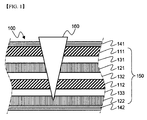
- FIG. 1 is a typical view schematically showing an example in which a conventional battery cell is locally damaged by a metal member.
- a battery cell 100 is configured to have a structure in which an electrode assembly 150, including positive electrodes 111 and 112 and negative electrodes 121 and 122 in a state in which separators 131, 132, and 133 are interposed respectively between the positive electrodes 111 and 112 and the negative electrodes 121 and 122, is mounted in battery cases 141 and 142. A portion of the battery cell 100 is damaged by a metal member 160, which has penetrated into the battery cell 100 from outside the battery cell 100.
- the metal member 160 has broken through the battery case 141 and then penetrated into the battery cell 100, with the result that the electrode assembly 150 has been locally damaged.
- the positive electrodes 111 and 112 and the negative electrodes 121 and 122, which constitute the electrode assembly 150 directly contact the metal member 160.
- an internal short-circuit occurs in the battery cell 100, with the result that the battery cell may catch fire or explode.
- the present invention has been made to solve the above problems and other technical problems that have yet to be resolved. It is an object of the present invention to provide a battery cell having an insulative material provided between an electrode assembly and a battery case for preventing the occurrence of a short-circuit in the battery cell or combustion of the battery cell due to direct contact between electrodes of the electrode assembly and a metal member penetrating into the battery cell when the battery cell is damaged by the metal member, thereby improving the safety of the battery cell.
- a battery cell configured such that an electrode assembly, including a positive electrode, a negative electrode, and a separator interposed between the positive electrode and the negative electrode, is mounted in a receiving part formed in a battery case, a positive electrode terminal and a negative electrode terminal protrude from at least one side of the electrode assembly, and an insulative material is provided between the electrode assembly and the battery case.
- the insulative material is provided between the electrode assembly and the battery case. Consequently, it is possible to prevent the occurrence of a short-circuit in the battery cell or combustion of the battery cell due to direct contact between the electrodes of the electrode assembly and the metal member penetrating into the battery cell when the battery cell is damaged by the metal member, thereby improving the safety of the battery cell.
- the insulative material is provided at the outer surface of a conventional electrode assembly or the inner surface of a conventional battery case regardless of the shape of the electrode assembly. Consequently, it is possible to improve the safety of the battery cell using a simple structure.
- the insulative material may be provided between the electrode assembly and the battery case in a state in which the insulative material is in tight contact with the outer surface of the electrode assembly or the inner surface of the battery case.
- the insulative material is provided in the electrode assembly, e.g. between the positive electrode and the negative electrode, the flow of ions between the electrodes may be disturbed by the insulative material. If the insulative material is provided at the outer surface of the battery case, on the other hand, the insulative material is exposed outward. In this case, the insulative material may be weakened by contaminants, may be deteriorated, or may be worn. As a result, the battery case may be partially or entirely exposed outward, and therefore the insulative material may not exhibit desired effects.
- the insulative material is provided between the electrode assembly and the battery case in a state in which the insulative material is in tight contact with the outer surface of the electrode assembly, which faces the inner surface of the battery case, or the inner surface of the battery case, which faces the outer surface of the electrode assembly.
- the insulative material is located between the metal member and the electrodes of the electrode assembly when the battery cell is damaged by the metal member. Consequently, it is possible to prevent direct contact between the metal member and the electrodes of the electrode assembly, thereby preventing the battery cell from catching fire or exploding, thus improving the safety of the battery cell
- the insulative material may be provided on both the outer surface of the electrode assembly and the inner surface of the battery case.
- the insulative material may be entirely or partially provided at the remaining region of the electrode assembly, excluding the positive electrode terminal and the negative electrode terminal of the electrode assembly, between the electrode assembly and the battery case.
- the insulative material may be locally provided only at a region of the electrode assembly that is exposed outward and may thus be easily broken, or may be entirely provided at the remaining region of the electrode assembly excluding the positive electrode terminal and the negative electrode terminal of the electrode assembly, depending on the shape of a device to which the battery cell is applied.
- the insulative material may be provided over 30 to 90%, preferably 50 to 70%, of the entire area of the outer surface of the electrode assembly or the inner surface of the battery case.
- the insulative material may have a thickness equivalent to 0.1 to 20%, preferably 5 to 10%, of the thickness of the electrode assembly.
- the insulative material is provided over less than 30% of the entire area of the outer surface of the electrode assembly or the inner surface of the battery case or if the insulative material has a thickness equivalent to less than 0.1% of the thickness of the electrode assembly, it is not possible to exhibit a desired short-circuit prevention effect.
- the insulative material is provided at more than 90% of the entire area of the outer surface of the electrode assembly or the inner surface of the battery case or if the insulative material has a thickness equivalent to more than 20% of the thickness of the electrode assembly, it may be difficult to impregnate the electrode assembly with an electrolyte.
- the insulative material is elastically stretched into a shape surrounding the outer surface of the metal member, which has penetrated into the electrode assembly.
- the insulative material is provided over less than 30% of the entire area of the outer surface of the electrode assembly or the inner surface of the battery case, therefore, it is not possible to effectively prevent direct contact between the metal member and the positive and negative electrodes of the electrode assembly to thus exhibit a desired safety improvement effect, since the insulative material does not cover the entirety of the outer surface of the metal member, which has penetrated into the electrode assembly.
- the insulative material has a thickness equivalent to less than 0.1% of the thickness of the electrode assembly, the insulative material may be damaged depending on the shape or rigidity of the metal member, whereby it is not possible to exhibit a desired safety improvement effect.
- the insulative material is not particularly restricted so long as the insulative material is provided at the outer surface of the electrode assembly or the inner surface of the battery case in order to exhibit a desired short-circuit prevention effect and a desired safety improvement effect while not affecting the performance of the battery cell.
- the insulative material may be insulative paint, Parafilm, foamed rubber, or a mixture thereof.
- the insulative paint may be at least one selected from a group consisting of acrylonitrile-butadiene rubber (NBR), styrene butadiene rubber (SBR), isobutylene isoprene rubber (IRR), chloroprene rubber (CR), and ethylene propylene diene monomer (EPDM).
- NBR acrylonitrile-butadiene rubber
- SBR styrene butadiene rubber
- IRR isobutylene isoprene rubber
- CR chloroprene rubber
- EPDM ethylene propylene diene monomer
- the foamed rubber may be natural rubber or synthetic rubber.
- the synthetic rubber may be at least one selected from a group consisting of styrene butadiene rubber, polychloroprene rubber, nitrile rubber, butyl rubber, butadiene rubber, isoprene rubber, ethylene propylene rubber, polysulfide rubber, silicone rubber, fluoro rubber, urethane rubber, and acrylic rubber.
- the structure of the electrode assembly constituting the battery cell according to the present invention is not particularly restricted so long as the electrode assembly is configured to have a structure including a positive electrode, a negative electrode, and a separator interposed between the positive electrode and the negative electrode.
- the electrode assembly may be configured to have a structure in which the positive electrode and the negative electrode are wound in a state in which the separator is interposed between the positive electrode and the negative electrode, a structure in which pluralities of positive electrodes and negative electrodes each having a predetermined size are sequentially stacked in a state in which separators are disposed respectively between the positive electrodes and the negative electrodes, or a structure in which pluralities of positive electrodes and negative electrodes each having a predetermined size are sequentially stacked in a state in which separators are disposed respectively between the positive electrodes and the negative electrodes to constitute a unit cell, after which a plurality of unit cells is sequentially folded while being placed on a separation film.
- the structure of the battery case constituting the battery cell according to the present invention is not particularly restricted so long as the electrode assembly with the above-stated construction is received in the battery case together with an electrolyte.
- the battery case may be a case configured to have a structure comprising a cylindrical or prismatic container and a cap loaded on the open upper end of the container or a pouch-shaped case made of a laminate sheet including a resin layer and a metal layer.
- the kind of the battery cell according to the present invention is not particularly restricted so long as the battery cell exhibits a desired effect while being configured to have the above-described structure.
- the battery cell according to the present invention may be a lithium secondary battery, such as a lithium ion battery or a lithium ion polymer battery, which exhibit high energy density, discharge voltage, and output stability.
- the construction, structure, and manufacturing method of the battery cell, including the lithium secondary battery, are well known in the art to which the present invention pertains, and therefore a detailed description thereof will be omitted.
- a device including the battery cell with the above-stated construction.
- the device may be any one selected from a group consisting of a cellular phone, a tablet computer, a laptop computer, a power tool, an electric vehicle, a hybrid electric vehicle, a plug-in hybrid electric vehicle, and a power storage apparatus.
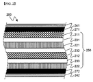
- FIG. 2 is a typical view showing the structure of a battery cell according to an embodiment of the present invention
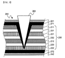
- FIG. 3 is a typical view schematically showing an example in which the battery cell is locally damaged by a metal member.
- a battery cell 200 is configured to have a structure in which an electrode assembly 250, including positive electrodes 211 and 212 and negative electrodes 221 and 222 in a state in which separators 231, 232, and 233 are interposed respectively between the positive electrodes 211 and 212 and the negative electrodes 221 and 222, is mounted in battery cases 241 and 242, and insulative materials 271 and 272 are provided respectively between the electrode assembly 250 and battery cases 241 and 242.
- a metal member 260 penetrates into the battery cell 200 from outside the battery cell 200, a portion of the battery cell 200 may be damaged. Specifically, the metal member 260 may break through the battery case 241 and may then penetrate into the battery cell 200, with the result that the electrode assembly 250 may be locally damaged.
- the insulative material 271 which is provided between the electrode assembly 250 and the battery case 241, is stretched into a shape surrounding the outer surface of the metal member 260, which has penetrated into the battery cell 200, based on the external shape of the metal member.
- the insulative material 271 prevents direct contact between the metal member 260, which has penetrated into the battery cell 200, and the positive electrodes 211 and 212 and the negative electrodes 221 and 222, which constitute the electrode assembly 250 of the battery cell 200, thereby preventing the occurrence of an internal short-circuit in the battery cell 200 or preventing the battery cell 200 from catching fire, thus improving the safety of the battery cell 200.
- FIG. 4 is a plan view typically showing regions of battery cells according to other embodiments of the present invention at which insulative elastic members are provided.
- a battery cell 410 according to the present invention is configured such that a positive electrode terminal 411 and a negative electrode terminal 412 protrude from one side of an electrode assembly 413, and another battery cell 420 according to the present invention is configured such that a positive electrode terminal 421 and a negative electrode terminal 422 protrude from opposite sides of an electrode assembly 423.
- An insulative material 414 is provided between the electrode assembly 413 of the battery cell 410 and a case (not shown), and an insulative material 424 is provided between the electrode assembly 423 of the battery cell 420 and a case (not shown).
- the insulative material 414 is provided at the remaining region of the electrode assembly 413, excluding the positive electrode terminal 411 and the negative electrode terminal 412 of the electrode assembly 413, between the electrode assembly 413 and the case
- the insulative material 424 is provided at the remaining region of the electrode assembly 423, excluding the positive electrode terminal 421 and the negative electrode terminal 422 of the electrode assembly 423, between the electrode assembly 423 and the case.
- a stacked type electrode assembly configured to have a structure in which positive electrodes and negative electrodes are stacked in a state in which separators are interposed respectively between the positive electrodes and the negative electrodes, was manufactured. Subsequently, an insulative tape, made of Teflon, was wound to cover the upper surface, the lower surface, and the opposite side surfaces of the electrode assembly. Subsequently, the electrode assembly was received in a pouch-shaped aluminum battery case, and then the battery case was sealed to manufacture a battery cell.
- a battery cell was manufactured in the same manner as in Example 1 except that no insulative tape was wound to cover the upper surface, the lower surface, and the opposite side surfaces of an electrode assembly.
- Example 1 and Comparative example 1 were connected to an external device.
- a needle-shaped member having a diameter of 15.8 mm and a weight of 91.9 kg was dropped from a height of 610 mm in order to apply impact to the upper surfaces of the battery cells manufactured according to Example 1 and Comparative example 1.
- the impact test was carried out nine times on different regions of the battery cells manufactured according to Example 1 and Comparative example 1 to check whether internal short-circuits occurred in the battery cells due to direct contact between the needle-shaped member and the electrodes.
- the results are shown in Table 1.
- Example 1 Comparative example 1 First time X O Second time X O Third time O X Internal short-circuit Fourth time X O Fifth time X O Sixth time X O Seventh time O O Eighth time X O Ninth time X O
- the insulative tape prevents direct contact between the needle-shaped member and the electrodes.
- an insulative material is provided between an electrode assembly and a battery case. Consequently, it is possible to prevent the occurrence of a short-circuit in the battery cell or combustion of the battery cell due to direct contact between electrodes of the electrode assembly and a metal member penetrating into the battery cell when the battery cell is damaged by the metal member.
- the insulative material is applicable to the battery cell regardless of the shape of the electrode assembly. Furthermore, only the insulative material is provided on the outer surface of a conventional electrode assembly or the inner surface of a conventional battery case. Consequently, it is possible to improve the safety of the battery cell using a simple structure.
Landscapes
- Chemical & Material Sciences (AREA)
- Chemical Kinetics & Catalysis (AREA)
- Electrochemistry (AREA)
- General Chemical & Material Sciences (AREA)
- Engineering & Computer Science (AREA)
- Manufacturing & Machinery (AREA)
- Secondary Cells (AREA)
- Connection Of Batteries Or Terminals (AREA)
- Sealing Battery Cases Or Jackets (AREA)
- Materials Engineering (AREA)
- Battery Mounting, Suspending (AREA)
Priority Applications (1)
| Application Number | Priority Date | Filing Date | Title |
|---|---|---|---|
| PL14866202T PL3051611T3 (pl) | 2013-11-26 | 2014-10-22 | Ogniwo baterii zawierające środki do zapobiegania zwarciu |
Applications Claiming Priority (2)
| Application Number | Priority Date | Filing Date | Title |
|---|---|---|---|
| KR20130144353 | 2013-11-26 | ||
| PCT/KR2014/009923 WO2015080380A1 (fr) | 2013-11-26 | 2014-10-22 | Élément de batterie comprenant des moyens de protection contre les courts-circuits |
Publications (4)
| Publication Number | Publication Date |
|---|---|
| EP3051611A1 true EP3051611A1 (fr) | 2016-08-03 |
| EP3051611A4 EP3051611A4 (fr) | 2017-05-10 |
| EP3051611B1 EP3051611B1 (fr) | 2019-12-18 |
| EP3051611B8 EP3051611B8 (fr) | 2020-03-11 |
Family
ID=53199291
Family Applications (1)
| Application Number | Title | Priority Date | Filing Date |
|---|---|---|---|
| EP14866202.6A Active EP3051611B8 (fr) | 2013-11-26 | 2014-10-22 | Élément de batterie comprenant des moyens de protection contre les courts-circuits |
Country Status (6)
| Country | Link |
|---|---|
| US (1) | US10553835B2 (fr) |
| EP (1) | EP3051611B8 (fr) |
| KR (1) | KR20150060520A (fr) |
| CN (1) | CN105684191B (fr) |
| PL (1) | PL3051611T3 (fr) |
| WO (1) | WO2015080380A1 (fr) |
Families Citing this family (7)
| Publication number | Priority date | Publication date | Assignee | Title |
|---|---|---|---|---|
| KR102186737B1 (ko) * | 2016-12-12 | 2020-12-04 | 주식회사 엘지화학 | 보호 부재를 포함하고 있는 전지셀 |
| KR102264633B1 (ko) * | 2017-06-16 | 2021-06-15 | 주식회사 엘지에너지솔루션 | 이차전지 |
| KR102326080B1 (ko) * | 2018-05-08 | 2021-11-11 | 주식회사 엘지에너지솔루션 | 리튬 금속 이차 전지용 케이스, 이를 포함하는 리튬 금속 이차 전지 및 이의 제조 방법 |
| DE102018128975B4 (de) * | 2018-11-19 | 2024-01-04 | Dr. Ing. H.C. F. Porsche Aktiengesellschaft | Batteriegehäuse einer Traktionsbatterie |
| FR3120762B1 (fr) | 2021-03-11 | 2023-12-29 | Thales Sa | Procede de desentrelacement rapide et robuste de trains d'impulsions |
| JP7380629B2 (ja) * | 2021-03-31 | 2023-11-15 | トヨタ自動車株式会社 | 組電池 |
| CN115224344B (zh) * | 2022-01-06 | 2024-08-06 | 惠州市禾信新能源科技有限公司 | 具有热失控阻断能力的锂离子动力电池模组及其控制方法 |
Family Cites Families (23)
| Publication number | Priority date | Publication date | Assignee | Title |
|---|---|---|---|---|
| US4818588A (en) * | 1985-11-20 | 1989-04-04 | Dai Nippon Insatsu Kabushiki Kaisha | Packaging materials |
| US5747192A (en) * | 1995-06-07 | 1998-05-05 | Avery Dennison Corporation | Single ply PSA labels for battery applications |
| US6294287B1 (en) | 1999-08-18 | 2001-09-25 | The Gillette Company | Alkaline cell with insulator |
| JP2003123714A (ja) * | 2001-10-16 | 2003-04-25 | Nec Tokin Tochigi Ltd | 電池パック |
| TWM240019U (en) * | 2002-08-09 | 2004-08-01 | Tai-Hung Lee | Rotary tube-cutter |
| JP4042613B2 (ja) | 2003-04-14 | 2008-02-06 | 日産自動車株式会社 | バイポーラ電池 |
| JP4238645B2 (ja) * | 2003-06-12 | 2009-03-18 | 日産自動車株式会社 | バイポーラ電池 |
| JP4595302B2 (ja) | 2003-09-04 | 2010-12-08 | 日産自動車株式会社 | バイポーラ電池 |
| JP4568123B2 (ja) * | 2005-01-12 | 2010-10-27 | 三洋電機株式会社 | 非水電解質電池 |
| KR100866767B1 (ko) * | 2006-07-10 | 2008-11-04 | 주식회사 엘지화학 | 이차전지용 안전부재 |
| KR100824874B1 (ko) * | 2006-08-24 | 2008-04-23 | 삼성에스디아이 주식회사 | 보호재 부착 캔형 이차전지 |
| KR100716596B1 (ko) * | 2007-03-26 | 2007-05-09 | 새한에너테크 주식회사 | 파우치형 리튬 2차전지 |
| JP4296522B2 (ja) * | 2007-08-23 | 2009-07-15 | トヨタ自動車株式会社 | 電池およびその製造方法 |
| KR101136799B1 (ko) * | 2008-04-18 | 2012-04-19 | 주식회사 엘지화학 | 슬림형의 전지팩 |
| US8035246B2 (en) * | 2010-01-07 | 2011-10-11 | American Superconductor Corporation | Torque limiting coupling for wind turbine |
| KR101264553B1 (ko) | 2010-11-05 | 2013-05-14 | 주식회사 엘지화학 | 안전성이 향상된 이차전지 |
| CN103168377A (zh) * | 2010-11-05 | 2013-06-19 | 株式会社Lg化学 | 具有改善的安全性的二次电池 |
| KR20120058676A (ko) * | 2010-11-05 | 2012-06-08 | 주식회사 엘지화학 | 안전성이 향상된 리튬 이차전지 및 전지팩 |
| KR101259356B1 (ko) | 2010-11-30 | 2013-04-30 | 주식회사 이노와이어리스 | Lte 기지국 에뮬레이터의 베이스밴드 처리 장치 |
| DE102012206075A1 (de) * | 2011-12-15 | 2013-06-20 | Robert Bosch Gmbh | Hartschalenzellgehäuse mit Dampfsperrschicht |
| JP6146953B2 (ja) | 2012-01-31 | 2017-06-14 | 昭和電工パッケージング株式会社 | 電池用外装材およびリチウム二次電池 |
| KR101533993B1 (ko) * | 2012-04-30 | 2015-07-06 | 주식회사 엘지화학 | 시트 부재 및 필름 부재를 포함하고 있는 전지모듈 |
| CN103325987B (zh) * | 2013-05-30 | 2015-08-26 | 广东天劲新能源科技股份有限公司 | 防针刺锂电池 |
-
2014
- 2014-10-22 EP EP14866202.6A patent/EP3051611B8/fr active Active
- 2014-10-22 CN CN201480059270.8A patent/CN105684191B/zh active Active
- 2014-10-22 PL PL14866202T patent/PL3051611T3/pl unknown
- 2014-10-22 US US15/033,438 patent/US10553835B2/en active Active
- 2014-10-22 WO PCT/KR2014/009923 patent/WO2015080380A1/fr active Application Filing
- 2014-11-04 KR KR1020140151945A patent/KR20150060520A/ko active Search and Examination
Also Published As
| Publication number | Publication date |
|---|---|
| KR20150060520A (ko) | 2015-06-03 |
| CN105684191B (zh) | 2019-02-26 |
| EP3051611B1 (fr) | 2019-12-18 |
| PL3051611T3 (pl) | 2020-05-18 |
| US10553835B2 (en) | 2020-02-04 |
| US20160276632A1 (en) | 2016-09-22 |
| EP3051611A4 (fr) | 2017-05-10 |
| WO2015080380A1 (fr) | 2015-06-04 |
| EP3051611B8 (fr) | 2020-03-11 |
| CN105684191A (zh) | 2016-06-15 |
Similar Documents
| Publication | Publication Date | Title |
|---|---|---|
| EP3051611B1 (fr) | Élément de batterie comprenant des moyens de protection contre les courts-circuits | |
| US11437683B2 (en) | Battery cell of venting structure using taping | |
| US11329348B2 (en) | Cylindrical battery cell comprising metal can having groove | |
| EP2822062B1 (fr) | Batterie secondaire comprenant un conducteur d'anode et un conducteur de cathode intégrés, et procédé de fabrication de celle-ci | |
| KR101792572B1 (ko) | 절연물질이 코팅되어 있는 전극을 포함하는 전지셀 | |
| US9853294B2 (en) | Secondary battery and manufacturing method thereof | |
| US10026938B2 (en) | Cylindrical lithium-ion cell | |
| US20100316905A1 (en) | Secondary battery | |
| US20150104672A1 (en) | Safety device of lithium-ion battery | |
| KR102186737B1 (ko) | 보호 부재를 포함하고 있는 전지셀 | |
| KR100914115B1 (ko) | 이차전지 | |
| KR20160111614A (ko) | 실링부에 벤팅부를 포함하고 있는 전지셀 | |
| EP2477257B1 (fr) | Batterie secondaire | |
| KR102331123B1 (ko) | 탄성 부재를 포함하는 원통형 전지셀의 캡 어셈블리 | |
| JP2022540538A (ja) | 円筒形電池および円筒形電池の製造方法 | |
| KR102108113B1 (ko) | 외주변이 절곡된 분리막을 포함하는 전극조립체 | |
| US9887394B2 (en) | Rechargeable battery including fluorescent coating layer | |
| KR20140001575U (ko) | 안전성이 향상된 구조를 가지는 전지셀 | |
| KR101763626B1 (ko) | 안전성 향상을 위한 구조의 도전부재를 포함하고 있는 전지셀 | |
| KR20150037309A (ko) | 형상 기억 합금으로 형성된 전지케이스를 포함하는 전지셀 | |
| KR101084919B1 (ko) | 이차전지 | |
| KR101763606B1 (ko) | 내압성의 전지케이스를 포함하는 이차전지 | |
| KR101023142B1 (ko) | 리튬 이차전지 | |
| KR20160015771A (ko) | 내진동 특성이 향상된 원통형 전지 | |
| KR20150066159A (ko) | 고용량, 고출력 리튬이온전지 캡 조립체 |
Legal Events
| Date | Code | Title | Description |
|---|---|---|---|
| PUAI | Public reference made under article 153(3) epc to a published international application that has entered the european phase |
Free format text: ORIGINAL CODE: 0009012 |
|
| 17P | Request for examination filed |
Effective date: 20160428 |
|
| AK | Designated contracting states |
Kind code of ref document: A1 Designated state(s): AL AT BE BG CH CY CZ DE DK EE ES FI FR GB GR HR HU IE IS IT LI LT LU LV MC MK MT NL NO PL PT RO RS SE SI SK SM TR |
|
| AX | Request for extension of the european patent |
Extension state: BA ME |
|
| DAX | Request for extension of the european patent (deleted) | ||
| A4 | Supplementary search report drawn up and despatched |
Effective date: 20170412 |
|
| RIC1 | Information provided on ipc code assigned before grant |
Ipc: H01M 2/02 20060101AFI20170406BHEP Ipc: H01M 10/052 20100101ALN20170406BHEP |
|
| GRAP | Despatch of communication of intention to grant a patent |
Free format text: ORIGINAL CODE: EPIDOSNIGR1 |
|
| STAA | Information on the status of an ep patent application or granted ep patent |
Free format text: STATUS: GRANT OF PATENT IS INTENDED |
|
| RIC1 | Information provided on ipc code assigned before grant |
Ipc: H01M 2/02 20060101AFI20190617BHEP Ipc: H01M 10/052 20100101ALN20190617BHEP |
|
| INTG | Intention to grant announced |
Effective date: 20190717 |
|
| GRAS | Grant fee paid |
Free format text: ORIGINAL CODE: EPIDOSNIGR3 |
|
| GRAJ | Information related to disapproval of communication of intention to grant by the applicant or resumption of examination proceedings by the epo deleted |
Free format text: ORIGINAL CODE: EPIDOSDIGR1 |
|
| GRAL | Information related to payment of fee for publishing/printing deleted |
Free format text: ORIGINAL CODE: EPIDOSDIGR3 |
|
| REG | Reference to a national code |
Ref country code: DE Ref legal event code: R079 Ref document number: 602014058740 Country of ref document: DE Free format text: PREVIOUS MAIN CLASS: H01M0002340000 Ipc: H01M0002020000 |
|
| STAA | Information on the status of an ep patent application or granted ep patent |
Free format text: STATUS: REQUEST FOR EXAMINATION WAS MADE |
|
| GRAR | Information related to intention to grant a patent recorded |
Free format text: ORIGINAL CODE: EPIDOSNIGR71 |
|
| STAA | Information on the status of an ep patent application or granted ep patent |
Free format text: STATUS: GRANT OF PATENT IS INTENDED |
|
| GRAA | (expected) grant |
Free format text: ORIGINAL CODE: 0009210 |
|
| STAA | Information on the status of an ep patent application or granted ep patent |
Free format text: STATUS: THE PATENT HAS BEEN GRANTED |
|
| INTC | Intention to grant announced (deleted) | ||
| RIC1 | Information provided on ipc code assigned before grant |
Ipc: H01M 10/052 20100101ALN20191025BHEP Ipc: H01M 2/02 20060101AFI20191025BHEP |
|
| INTG | Intention to grant announced |
Effective date: 20191106 |
|
| AK | Designated contracting states |
Kind code of ref document: B1 Designated state(s): AL AT BE BG CH CY CZ DE DK EE ES FI FR GB GR HR HU IE IS IT LI LT LU LV MC MK MT NL NO PL PT RO RS SE SI SK SM TR |
|
| REG | Reference to a national code |
Ref country code: CH Ref legal event code: EP |
|
| REG | Reference to a national code |
Ref country code: IE Ref legal event code: FG4D |
|
| REG | Reference to a national code |
Ref country code: DE Ref legal event code: R096 Ref document number: 602014058740 Country of ref document: DE |
|
| REG | Reference to a national code |
Ref country code: AT Ref legal event code: REF Ref document number: 1215570 Country of ref document: AT Kind code of ref document: T Effective date: 20200115 |
|
| REG | Reference to a national code |
Ref country code: CH Ref legal event code: PK Free format text: BERICHTIGUNG B8 |
|
| RAP2 | Party data changed (patent owner data changed or rights of a patent transferred) |
Owner name: LG CHEM, LTD. |
|
| REG | Reference to a national code |
Ref country code: NL Ref legal event code: MP Effective date: 20191218 |
|
| PG25 | Lapsed in a contracting state [announced via postgrant information from national office to epo] |
Ref country code: GR Free format text: LAPSE BECAUSE OF FAILURE TO SUBMIT A TRANSLATION OF THE DESCRIPTION OR TO PAY THE FEE WITHIN THE PRESCRIBED TIME-LIMIT Effective date: 20200319 Ref country code: NO Free format text: LAPSE BECAUSE OF FAILURE TO SUBMIT A TRANSLATION OF THE DESCRIPTION OR TO PAY THE FEE WITHIN THE PRESCRIBED TIME-LIMIT Effective date: 20200318 Ref country code: BG Free format text: LAPSE BECAUSE OF FAILURE TO SUBMIT A TRANSLATION OF THE DESCRIPTION OR TO PAY THE FEE WITHIN THE PRESCRIBED TIME-LIMIT Effective date: 20200318 Ref country code: FI Free format text: LAPSE BECAUSE OF FAILURE TO SUBMIT A TRANSLATION OF THE DESCRIPTION OR TO PAY THE FEE WITHIN THE PRESCRIBED TIME-LIMIT Effective date: 20191218 Ref country code: LT Free format text: LAPSE BECAUSE OF FAILURE TO SUBMIT A TRANSLATION OF THE DESCRIPTION OR TO PAY THE FEE WITHIN THE PRESCRIBED TIME-LIMIT Effective date: 20191218 Ref country code: SE Free format text: LAPSE BECAUSE OF FAILURE TO SUBMIT A TRANSLATION OF THE DESCRIPTION OR TO PAY THE FEE WITHIN THE PRESCRIBED TIME-LIMIT Effective date: 20191218 Ref country code: LV Free format text: LAPSE BECAUSE OF FAILURE TO SUBMIT A TRANSLATION OF THE DESCRIPTION OR TO PAY THE FEE WITHIN THE PRESCRIBED TIME-LIMIT Effective date: 20191218 |
|
| REG | Reference to a national code |
Ref country code: LT Ref legal event code: MG4D |
|
| PG25 | Lapsed in a contracting state [announced via postgrant information from national office to epo] |
Ref country code: HR Free format text: LAPSE BECAUSE OF FAILURE TO SUBMIT A TRANSLATION OF THE DESCRIPTION OR TO PAY THE FEE WITHIN THE PRESCRIBED TIME-LIMIT Effective date: 20191218 Ref country code: RS Free format text: LAPSE BECAUSE OF FAILURE TO SUBMIT A TRANSLATION OF THE DESCRIPTION OR TO PAY THE FEE WITHIN THE PRESCRIBED TIME-LIMIT Effective date: 20191218 |
|
| PG25 | Lapsed in a contracting state [announced via postgrant information from national office to epo] |
Ref country code: AL Free format text: LAPSE BECAUSE OF FAILURE TO SUBMIT A TRANSLATION OF THE DESCRIPTION OR TO PAY THE FEE WITHIN THE PRESCRIBED TIME-LIMIT Effective date: 20191218 |
|
| PG25 | Lapsed in a contracting state [announced via postgrant information from national office to epo] |
Ref country code: PT Free format text: LAPSE BECAUSE OF FAILURE TO SUBMIT A TRANSLATION OF THE DESCRIPTION OR TO PAY THE FEE WITHIN THE PRESCRIBED TIME-LIMIT Effective date: 20200513 Ref country code: NL Free format text: LAPSE BECAUSE OF FAILURE TO SUBMIT A TRANSLATION OF THE DESCRIPTION OR TO PAY THE FEE WITHIN THE PRESCRIBED TIME-LIMIT Effective date: 20191218 Ref country code: CZ Free format text: LAPSE BECAUSE OF FAILURE TO SUBMIT A TRANSLATION OF THE DESCRIPTION OR TO PAY THE FEE WITHIN THE PRESCRIBED TIME-LIMIT Effective date: 20191218 Ref country code: EE Free format text: LAPSE BECAUSE OF FAILURE TO SUBMIT A TRANSLATION OF THE DESCRIPTION OR TO PAY THE FEE WITHIN THE PRESCRIBED TIME-LIMIT Effective date: 20191218 Ref country code: RO Free format text: LAPSE BECAUSE OF FAILURE TO SUBMIT A TRANSLATION OF THE DESCRIPTION OR TO PAY THE FEE WITHIN THE PRESCRIBED TIME-LIMIT Effective date: 20191218 |
|
| PG25 | Lapsed in a contracting state [announced via postgrant information from national office to epo] |
Ref country code: SM Free format text: LAPSE BECAUSE OF FAILURE TO SUBMIT A TRANSLATION OF THE DESCRIPTION OR TO PAY THE FEE WITHIN THE PRESCRIBED TIME-LIMIT Effective date: 20191218 Ref country code: IS Free format text: LAPSE BECAUSE OF FAILURE TO SUBMIT A TRANSLATION OF THE DESCRIPTION OR TO PAY THE FEE WITHIN THE PRESCRIBED TIME-LIMIT Effective date: 20200418 Ref country code: SK Free format text: LAPSE BECAUSE OF FAILURE TO SUBMIT A TRANSLATION OF THE DESCRIPTION OR TO PAY THE FEE WITHIN THE PRESCRIBED TIME-LIMIT Effective date: 20191218 |
|
| REG | Reference to a national code |
Ref country code: DE Ref legal event code: R097 Ref document number: 602014058740 Country of ref document: DE |
|
| REG | Reference to a national code |
Ref country code: AT Ref legal event code: MK05 Ref document number: 1215570 Country of ref document: AT Kind code of ref document: T Effective date: 20191218 |
|
| PLBE | No opposition filed within time limit |
Free format text: ORIGINAL CODE: 0009261 |
|
| STAA | Information on the status of an ep patent application or granted ep patent |
Free format text: STATUS: NO OPPOSITION FILED WITHIN TIME LIMIT |
|
| PG25 | Lapsed in a contracting state [announced via postgrant information from national office to epo] |
Ref country code: DK Free format text: LAPSE BECAUSE OF FAILURE TO SUBMIT A TRANSLATION OF THE DESCRIPTION OR TO PAY THE FEE WITHIN THE PRESCRIBED TIME-LIMIT Effective date: 20191218 Ref country code: ES Free format text: LAPSE BECAUSE OF FAILURE TO SUBMIT A TRANSLATION OF THE DESCRIPTION OR TO PAY THE FEE WITHIN THE PRESCRIBED TIME-LIMIT Effective date: 20191218 |
|
| 26N | No opposition filed |
Effective date: 20200921 |
|
| REG | Reference to a national code |
Ref country code: DE Ref legal event code: R079 Ref document number: 602014058740 Country of ref document: DE Free format text: PREVIOUS MAIN CLASS: H01M0002020000 Ipc: H01M0050100000 |
|
| PG25 | Lapsed in a contracting state [announced via postgrant information from national office to epo] |
Ref country code: AT Free format text: LAPSE BECAUSE OF FAILURE TO SUBMIT A TRANSLATION OF THE DESCRIPTION OR TO PAY THE FEE WITHIN THE PRESCRIBED TIME-LIMIT Effective date: 20191218 Ref country code: SI Free format text: LAPSE BECAUSE OF FAILURE TO SUBMIT A TRANSLATION OF THE DESCRIPTION OR TO PAY THE FEE WITHIN THE PRESCRIBED TIME-LIMIT Effective date: 20191218 |
|
| PG25 | Lapsed in a contracting state [announced via postgrant information from national office to epo] |
Ref country code: IT Free format text: LAPSE BECAUSE OF FAILURE TO SUBMIT A TRANSLATION OF THE DESCRIPTION OR TO PAY THE FEE WITHIN THE PRESCRIBED TIME-LIMIT Effective date: 20191218 |
|
| REG | Reference to a national code |
Ref country code: CH Ref legal event code: PL |
|
| PG25 | Lapsed in a contracting state [announced via postgrant information from national office to epo] |
Ref country code: MC Free format text: LAPSE BECAUSE OF FAILURE TO SUBMIT A TRANSLATION OF THE DESCRIPTION OR TO PAY THE FEE WITHIN THE PRESCRIBED TIME-LIMIT Effective date: 20191218 Ref country code: LU Free format text: LAPSE BECAUSE OF NON-PAYMENT OF DUE FEES Effective date: 20201022 |
|
| REG | Reference to a national code |
Ref country code: BE Ref legal event code: MM Effective date: 20201031 |
|
| PG25 | Lapsed in a contracting state [announced via postgrant information from national office to epo] |
Ref country code: BE Free format text: LAPSE BECAUSE OF NON-PAYMENT OF DUE FEES Effective date: 20201031 Ref country code: CH Free format text: LAPSE BECAUSE OF NON-PAYMENT OF DUE FEES Effective date: 20201031 Ref country code: LI Free format text: LAPSE BECAUSE OF NON-PAYMENT OF DUE FEES Effective date: 20201031 |
|
| PG25 | Lapsed in a contracting state [announced via postgrant information from national office to epo] |
Ref country code: IE Free format text: LAPSE BECAUSE OF NON-PAYMENT OF DUE FEES Effective date: 20201022 |
|
| PG25 | Lapsed in a contracting state [announced via postgrant information from national office to epo] |
Ref country code: TR Free format text: LAPSE BECAUSE OF FAILURE TO SUBMIT A TRANSLATION OF THE DESCRIPTION OR TO PAY THE FEE WITHIN THE PRESCRIBED TIME-LIMIT Effective date: 20191218 Ref country code: MT Free format text: LAPSE BECAUSE OF FAILURE TO SUBMIT A TRANSLATION OF THE DESCRIPTION OR TO PAY THE FEE WITHIN THE PRESCRIBED TIME-LIMIT Effective date: 20191218 Ref country code: CY Free format text: LAPSE BECAUSE OF FAILURE TO SUBMIT A TRANSLATION OF THE DESCRIPTION OR TO PAY THE FEE WITHIN THE PRESCRIBED TIME-LIMIT Effective date: 20191218 |
|
| PG25 | Lapsed in a contracting state [announced via postgrant information from national office to epo] |
Ref country code: MK Free format text: LAPSE BECAUSE OF FAILURE TO SUBMIT A TRANSLATION OF THE DESCRIPTION OR TO PAY THE FEE WITHIN THE PRESCRIBED TIME-LIMIT Effective date: 20191218 |
|
| P01 | Opt-out of the competence of the unified patent court (upc) registered |
Effective date: 20230408 |
|
| REG | Reference to a national code |
Ref country code: DE Ref legal event code: R081 Ref document number: 602014058740 Country of ref document: DE Owner name: LG ENERGY SOLUTION, LTD., KR Free format text: FORMER OWNER: LG CHEM. LTD., SEOUL/SOUL, KR |
|
| REG | Reference to a national code |
Ref country code: GB Ref legal event code: 732E Free format text: REGISTERED BETWEEN 20230824 AND 20230831 |
|
| PGFP | Annual fee paid to national office [announced via postgrant information from national office to epo] |
Ref country code: GB Payment date: 20230920 Year of fee payment: 10 |
|
| PGFP | Annual fee paid to national office [announced via postgrant information from national office to epo] |
Ref country code: PL Payment date: 20230921 Year of fee payment: 10 Ref country code: FR Payment date: 20230922 Year of fee payment: 10 |
|
| PGFP | Annual fee paid to national office [announced via postgrant information from national office to epo] |
Ref country code: DE Payment date: 20230920 Year of fee payment: 10 |