EP3051522A1 - Verschliessbarer dokumentenbehälter - Google Patents
Verschliessbarer dokumentenbehälter Download PDFInfo
- Publication number
- EP3051522A1 EP3051522A1 EP16153289.0A EP16153289A EP3051522A1 EP 3051522 A1 EP3051522 A1 EP 3051522A1 EP 16153289 A EP16153289 A EP 16153289A EP 3051522 A1 EP3051522 A1 EP 3051522A1
- Authority
- EP
- European Patent Office
- Prior art keywords
- base plate
- cover plate
- plate
- lying
- locking position
- Prior art date
- Legal status (The legal status is an assumption and is not a legal conclusion. Google has not performed a legal analysis and makes no representation as to the accuracy of the status listed.)
- Granted
Links
Images



Classifications
-
- G—PHYSICS
- G09—EDUCATION; CRYPTOGRAPHY; DISPLAY; ADVERTISING; SEALS
- G09F—DISPLAYING; ADVERTISING; SIGNS; LABELS OR NAME-PLATES; SEALS
- G09F1/00—Cardboard or like show-cards of foldable or flexible material
- G09F1/10—Supports or holders for show-cards
-
- G—PHYSICS
- G09—EDUCATION; CRYPTOGRAPHY; DISPLAY; ADVERTISING; SEALS
- G09F—DISPLAYING; ADVERTISING; SIGNS; LABELS OR NAME-PLATES; SEALS
- G09F7/00—Signs, name or number plates, letters, numerals, or symbols; Panels or boards
- G09F7/02—Signs, plates, panels or boards using readily-detachable elements bearing or forming symbols
- G09F7/08—Signs, plates, panels or boards using readily-detachable elements bearing or forming symbols the elements being secured or adapted to be secured by means of grooves, rails, or slits
- G09F7/10—Signs, plates, panels or boards using readily-detachable elements bearing or forming symbols the elements being secured or adapted to be secured by means of grooves, rails, or slits and slideably mounted
-
- G—PHYSICS
- G09—EDUCATION; CRYPTOGRAPHY; DISPLAY; ADVERTISING; SEALS
- G09F—DISPLAYING; ADVERTISING; SIGNS; LABELS OR NAME-PLATES; SEALS
- G09F7/00—Signs, name or number plates, letters, numerals, or symbols; Panels or boards
- G09F7/18—Means for attaching signs, plates, panels, or boards to a supporting structure
- G09F7/22—Means for attaching signs, plates, panels, or boards to a supporting structure for rotatably or swingably mounting, e.g. for boards adapted to be rotated by the wind
Definitions
- the present invention relates to a device, in particular a document container, for the lockable storage of a sheet of paper, in particular a work permit.
- a work permit can be created by hand or created electronically by completing an appropriate form and then printed out. It is known to provide the printed work permit with a barcode that can be used to release after commissioning and cancellation of the safety measures, a restart of the system.
- the present invention has for its object to provide a way to ensure that accidental re-commissioning of the system while working, especially by reading a printed on the work permit barcode can be prevented.
- a device having the features of claim 1, and in particular by a device, in particular a document container, with a base plate and an at least partially transparent cover plate for lockable storage of a sheet of paper, in particular a work permit, between a front of Base plate and a back of the cover plate, wherein the cover plate is held in a composite with the base plate on the base plate and between a locking position in which removal of the sheet is prevented from the device, and a release position in which the removal of the sheet is made possible , Slidably guided, and wherein the cover plate in the locked position by means of locking elements, in particular padlocks, on the base plate can be fixed.
- a work permit can thus be stored in the device and secured against removal from the device.
- the persons executing the work each hang a personalized padlock or the like into the device and close the respective padlock.
- the re-commissioning of the affected system can therefore only be done when all persons have their padlocks again removed from the device and the work permit can be removed again from the device.
- it is thus ensured that reading a barcode printed on a work permit is not possible without the knowledge of the persons executing the work.
- access to a work permit can be closed multiple times, and the device can be used for group lockout in connection with work on equipment and machinery.
- the inventive device for storing the work permit or another printed on a particular individual sheet of paper document comprises a particular rigid base plate and one in particular rigid cover plate between which the document is held.
- the cover plate is at least partially transparent so that the document stored in the device can continue to be read by persons involved in the exclusion, and in particular recognize the persons performing the work in the presence of a plurality of such devices for different exclusion points at one and / or several different installations to which device they need to attach their respective padlock.
- the cover plate may be formed, for example, as an acrylic glass plate. Acrylic glass is aging and UV resistant. In addition, acrylic glass is available as a sheet product and easy to process.
- the base plate may for example be formed from sheet metal.
- the cover plate and the base plate are formed such that the cover plate can be held in the base plate and slidably guided.
- the cover plate can assume a blocking position in which the cover plate is fixed to the base plate, and the document can not be removed from the device. From the blocking position can - if no padlocks or the like are attached to the device - the cover plate are moved to a release position. The release position is reached when the respective document can be removed from the device.
- the chosen construction has, among other things, the advantage that the base and cover plates can be manufactured separately from one another and / or from different materials, the choice of which can be matched to the requirements imposed on the respective plate.
- by moving the cover plate can be easily and quickly created an uncomplicated and disability-free access to the document for its removal from the device.
- first securing openings formed in the cover plate are arranged in the region of the second securing apertures formed in the base plate, so that a respective padlock can be suspended in respectively superimposed first and second securing apertures.
- the base plate on its front side on two opposite sides extending in the direction of displacement grooves, in which the cover plate, in particular with two opposite edges, is guided in the composite with the base plate state.
- the cover plate can therefore be inserted on both sides in each case one of the two grooves of the base plate and thereby slidably held on the base plate.
- the two receiving grooves are each formed by a protruding from the base plate in the direction of the cover plate web, wherein the webs are each angled inwardly at its free end.
- the two webs may each be L-shaped.
- the two receiving grooves are formed by bending at two opposite edges of the base plate.
- the two receiving grooves can each form a particular L-shaped flanged edge of the base plate.
- the two grooves can thus be prepared in a simple manner that a correspondingly tailored base plate is formed on two opposite edges by appropriate bending.
- the two receiving grooves are open at their ends lying in the direction of the locking position in the direction of displacement. In this way, it can be achieved that dust or dirt located in the region of the receiving grooves is pushed out of the receiving grooves during insertion of the cover plate and does not collect at the ends of the receiving grooves lying in the direction of the blocking position.
- the two receiving grooves are each, in particular also, open at its lying in the direction of the release position end, since from there the cover plate is inserted.
- the device at its lying in the direction of the locking position end and / or at its lying in the direction of the release position a lift-off against lifting the cover plate from the base plate in the locked position.
- the anti-lifting device or a part thereof at the same time also forms a stop for the cover plate in the displacement direction, in particular when the cover plate is displaced in the direction of the locking position.
- the device can therefore have at its end lying in the direction of the locking position means which forms both a lift-off against lifting the cover plate from the base plate in the locked position or a part thereof and a stop for the cover plate in the direction of displacement.
- the device has a stop for the cover plate in the displacement direction at its end lying in the direction of the blocking position.
- the cover plate at its lying in the direction of the locking position end at least one insertion tongue, which in the locking position in a corresponding, on the base plate trained pocket engages.
- the respective insertion tongue is preferably integrally formed on the cover plate.
- the respective pocket may in particular be a slotted depression formed in the base plate.
- the cover plate at its lying in the direction of the release position end on its rear side projecting from the cover plate in the direction of the base plate web, which is angled inwardly at its free end, in particular a bend, to in the locking position, the corresponding end of To surround the base plate.
- the first securing openings are arranged further inside than the web encompassing the base plate.
- first securing openings and the second securing openings can each be formed on the end of the cover plate and the base plate lying in the direction of the release position. This is particularly advantageous when the device is fixed with its lying in the direction of the locking position end to a wall bracket for the device.
- the securing openings are therefore easily accessible for attaching or removing the locking elements to or from the device.
- the base plate on two opposite sides at its lying in the direction of the locking position end in each case a connecting pin, with which the device in a plurality of such devices receiving wall mount, in particular a wall bracket, can be suspended. It is preferred if one of the two connecting pins has a greater length than the other of the two connecting pins. When hanging the device can then first the longer Connecting pin and then the shorter connecting pin are hung in the wall bracket.
- the connecting pins can be provided for reinforcement each with a bead.
- the invention further relates to a wall bracket for a device, as described above, with a base plate, from the two spaced apart, mutually parallel legs at an angle, in particular at right angles, protrude.
- a row of holes for the particular pivotal mounting of the pivot pin of the devices is formed in the legs.
- the two rows of holes extend parallel to each other and each obliquely to the base plate.
- tilting the rows of holes can be achieved that one side of the wall bracket is preferred such that in the wall bracket pivotally hinged devices in a state in which they are all pivoted on one side of the wall bracket, as close to the wall.
- the one row of holes is arranged further away from the base plate than the other row of holes.
- a lower row of holes is farther from the base plate than an upper row of holes.
- the invention further relates to a system with at least two wall mounts, each as described above, wherein the wall mounts have different colors. If several wall brackets, which are assigned to different departments, crafts or external companies, are mounted in the immediate vicinity of each other, the different colors allow each employee to quickly find the relevant wall bracket.
- the invention further relates to a system with a wall mount as described above and at least one device, each as described above.
- the respective device is pivotally suspended or mounted in the wall bracket.
- a plate-shaped document container 11 is shown in which a document 13 by means of padlocks 15, of which in Fig. 1 only one thing is shown lockable and thus can be stored inaccessible.
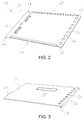
- the document 13 is between the front of a base plate 17 made of sheet metal, in Fig. 2 is closer, and the back of a made of acrylic glass cover plate 19, the Fig. 3 is shown in more detail, included. Since the cover plate 19 is made of a transparent or transparent material is in Fig. 1 the document 13 visible through the cover plate 19 therethrough.
- the document 13 is in particular a work permit with a barcode which can ultimately be used to release a restart of a system temporarily put out of operation for maintenance or repair.
- the work permit 13 is placed in the document container 11, which is also referred to as a document box, laid, and each of the aforementioned persons attaches a personalized padlock 15 to the document container 11, so that the work permit 13 can only be removed from the document container 11, when all parties involved their curtain lock 15 again from the Document container 11 have removed.
- the base plate 17 and the cover plate 19 are assembled and interconnected such that the cover plate 19 is slidably guided on the front side of the base plate 17.
- the base plate 19 on its front side at its two opposite longitudinal sides 21 each have a receiving groove 23 into which the cover plate 19 engages with their respective longitudinal edges and along which the cover plate 19 is slidable.
- the two grooves 23 are made by bending the corresponding cut edges of the base plate 19 and thereby form an L-shaped angled, from the base plate 17th in the direction of the cover plate 19 projecting web. Due to the sliding guide, the cover plate 19 is also held on the base plate 17.
- the cover plate 19 is between a blocking position, as in Fig. 1 is shown, and a release position, not shown, in which the cover plate 19 from its position according to Fig. 1 moved to the right, movable.
- the cover plate 19 can therefore be pushed laterally out of the locked position.
- the locked position the work permit 13 is completely covered by the cover plate 19, and the work permit 13 can not be removed from the document container 11.
- the release position the cover plate 19 at least partially releases the work permit 13, and the work permit 13 can be removed from the document container 11.
- the two receiving grooves 23 are not closed at their lying in the direction of the locking position ends in the direction of displacement. In this way, a cleaning function can be realized since dust or dirt, which is located in the region of the receiving grooves 23, can be pushed out of the receiving grooves 23 when the cover plate 19 is inserted at the ends of the receiving grooves 23 located in the direction of the blocking position.
- first securing openings 25 and in the base plate 17 at its lying in the direction of the release position In order to prevent displacement of the cover plate 19 from the locked position to the release position, in the cover plate 19 at its lying in the direction of the release position a plurality of first securing openings 25 and in the base plate 17 at its lying in the direction of the release position several second securing openings 27th intended.
- the number and arrangement of the first securing openings 25 corresponds to the number and arrangement of the second securing openings 27.
- the first securing openings 25 and the second securing openings 27 are each arranged along a row, the rows being aligned with one another in the blocking position of the cover plate 19.
- each cover plate 19 each have a first securing opening 25 arranged over an associated second securing opening 27, so that in the pairs consisting of a respective first securing opening 25 and a second securing openings 27 each a curtain lock 15 can be hung and closed.
- the cover plate 19 can be fixed to the base plate 17 by means of the padlocks 15.
- the document container 11 at its lying in the direction of the locking position end to a lift-off to prevent the cover plate 19 can be lifted in the locked position of the base plate 17 so as to try the work permit 13 despite attached padlocks 15 off to remove the document container 11.
- the lift-off comprises two insertion tongues 29 projecting from the cover plate 19 in the direction of the blocking position, which engage in the blocking position into two corresponding pockets 31 formed in the base plate 17.
- the pockets 31 are made by appropriate slitting and deep drawing of the base plate 17 in the respective pocket area.
- the pockets 31 simultaneously act as a stop for the cover plate 19 when moving the cover plate 19 in the direction of the locking position and thus fulfill a dual function.
- the cover plate 19 is provided with a field 35 which is completely blackened, so that the work permit 15 in the area which is located below the blackening 35 can not be read through the cover plate 19 therethrough.
- the blackening 35 is preferably located at the back of the cover plate 19 or is integrated with the cover plate 19 to prevent scratching of the blackening 35 or the like from the outside.
- the aforementioned barcode of the work permit 15. In the area hidden by the field 35 is the aforementioned barcode of the work permit 15. Thus it can be prevented the bar code is read through the cover plate 19 when the work permit 15 is closed in the document container 11.
- the opacity of the panel 35 can also be achieved by other suitable measures, for example matting, satin finishing, pixelation or the like.
- the cover plate 19 is provided at its lying in the direction of the release position end with a bend 33 which extends from its rear side in the direction of the base plate 17.
- the bend 33 ultimately forms a web which is angled inwardly at its free end. Due to the bent front edge of the cover plate 19, the lying in the direction of the release position end of the base plate 17 are encompassed by the cover plate 19, whereby the stability of the document container 11 is increased in the assembled state.
- the bend 33 also acts as protection against ingress of dust into the space between the base plate 17 and the cover plate 19th
- the base plate 17 has at its end lying in the direction of the locking position on both sides in each case a connecting pin 37, with which the document container 11 - together with other document containers 11 - can be hung in a wall bracket 39, as shown in Fig. 4 is shown.
- the wall bracket 39 is made of sheet metal.
- the document container 11 - depending on the number of recorded in the wall mount 39 document container 11 and the size of the padlocks 15 - are each folded over by almost 180 °.
- the wall bracket 39 comprises a base plate 41 which can be mounted with its rear side to a wall, and two mutually parallel legs 43 which project from the base plate 41 to the front at an angle of 90 °.
- the distance between the two legs 43 to each other is matched to the height of the document container 11.
- the two rows of holes 45, 45 'extend obliquely to the base plate 41 Fig. 4 achieved that the document container 11 in its position in which they are folded to the wall bracket 39 to the right, are arranged as close as possible to the wall on this page.
- Fig. 5 results, the lower row of holes 45 is further away from the base plate 41 and thus ultimately further away from a wall than the upper row of holes 45 '.
- the wall mount 39 is therefore tilted backwards in a state attached to a wall, so that the document container 11 always automatically fall either to the left or right and thus as little as possible protrude into the room.
- the upper connecting pin 37 is first hooked into a hole of the row of holes 45 'of the upper leg 43, and then the lower connecting pin 37 with short, reversible bending away of the lower leg 43 in a respective, corresponding to the selected upper hole Hole of the row of holes 45 of the lower leg 43 mounted.
- the lower connecting pin 37 is shorter than the upper connecting pin 37, so that the attachment of the lower connecting pin 37 is facilitated.
Landscapes
- Physics & Mathematics (AREA)
- General Physics & Mathematics (AREA)
- Engineering & Computer Science (AREA)
- Theoretical Computer Science (AREA)
- Purses, Travelling Bags, Baskets, Or Suitcases (AREA)
- Packages (AREA)
- Refuse Receptacles (AREA)
Abstract
Description
- Die vorliegende Erfindung betrifft eine Vorrichtung, insbesondere einen Dokumentenbehälter, zur verschließbaren Aufbewahrung eines Blatts aus Papier, insbesondere eines Arbeitserlaubnisscheins.
- Für Arbeiten wie Wartung, Reparatur oder Reinigung werden elektrische Anlagen außer Betrieb gesetzt, beispielsweise durch Abtrennen der Anlage oder eines Teils der Anlage von der Spannungsversorgung, und durch Sicherungsmaßnahmen gegen eine Wiederinbetriebnahme gesichert, um Gefährdungen der die Arbeiten ausführenden eigenen Mitarbeiter oder Mitarbeiter von Fremdfirmen für die Dauer der Arbeiten zu vermeiden. Dabei werden die Gefährdungen und alle für die Arbeiten relevanten Informationen und Instruktionen für ein sicheres Arbeiten in einem Arbeitserlaubnisschein dokumentiert. Ein Arbeitserlaubnisschein kann durch Ausfüllen eines entsprechenden Formulars per Hand erstellt oder elektronisch erstellt und anschließend ausgedruckt werden. Dabei ist es bekannt, den ausgedruckten Arbeitserlaubnisschein mit einem Barcode zu versehen, der dazu verwendet werden kann, nach Abschluss der Arbeiten und Aufhebung der Sicherungsmaßnahmen eine Wiederinbetriebnahme der Anlage freizugeben.
- Der vorliegenden Erfindung liegt die Aufgabe zugrunde, eine Möglichkeit anzugeben, mit der sichergestellt werden kann, dass eine versehentliche Wiederinbetriebnahme der Anlage noch während der laufenden Arbeiten, insbesondere durch Lesen eines auf dem Arbeitserlaubnisschein aufgedruckten Barcodes, verhindert werden kann.
- Die Aufgabe wird durch eine Vorrichtung mit den Merkmalen des Anspruchs 1 gelöst, und insbesondere durch eine Vorrichtung, insbesondere einen Dokumentenbehälter, mit einer Grundplatte und einer zumindest bereichsweise transparenten Deckplatte, zur verschließbaren Aufbewahrung eines Blatts aus Papier, insbesondere eines Arbeitserlaubnisscheins, zwischen einer Vorderseite der Grundplatte und einer Rückseite der Deckplatte, wobei die Deckplatte in einem mit der Grundplatte zusammengesetzten Zustand an der Grundplatte gehalten und zwischen einer Sperrposition, in der ein Entnehmen des Blatts aus der Vorrichtung verhindert wird, und einer Freigabeposition, in der das Entnehmen des Blatts ermöglicht wird, verschiebbar geführt ist, und wobei die Deckplatte in der Sperrposition mittels Verriegelungselementen, insbesondere Vorhangschlössern, an der Grundplatte festsetzbar ist.
- Ein Arbeitserlaubnisschein kann somit in der Vorrichtung aufbewahrt und gegen ein Entnehmen aus der Vorrichtung gesichert werden. Hierzu hängen die die Arbeiten ausführenden Personen jeweils ein personalisiertes Vorhangschloss oder dergleichen in die Vorrichtung ein und verschließen das jeweilige Vorhangschloss. Die Wiederinbetriebnahme der betroffenen Anlage kann daher erst dann erfolgen, wenn alle Personen ihre Vorhangschlösser wieder von der Vorrichtung entfernt haben und der Arbeitserlaubnisschein wieder aus der Vorrichtung entnommen werden kann. Insbesondere wird also gewährleistet, dass ein Lesen eines auf einem Arbeitserlaubnisschein aufgedruckten Barcodes nicht ohne die Kenntnis der die Arbeiten ausführenden Personen möglich ist. Letztlich kann also der Zugang zu einem Arbeitserlaubnisschein mehrfach verschlossen werden, und die Vorrichtung kann für einen Gruppen-Ausschluss (Group Lockout) im Zusammenhang mit Arbeiten an Anlagen und Maschinen verwendet werden.
- Die erfindungsgemäße Vorrichtung zur Aufbewahrung des Arbeitserlaubnisscheins oder eines anderen auf ein insbesondere einzelnes Blatt Papier gedruckten Dokuments umfasst eine insbesondere starre Grundplatte und eine insbesondere starre Deckplatte, zwischen denen das Dokument gehalten wird. Die Deckplatte ist zumindest bereichsweise transparent ausgebildet, damit das in der Vorrichtung aufbewahrte Dokument von in den Ausschluss involvierten Personen weiterhin gelesen werden kann und insbesondere die die Arbeiten ausführenden Personen bei Vorhandensein einer Vielzahl derartiger Vorrichtungen für verschiedene Ausschlusspunkte an einer und/oder mehreren unterschiedlichen Anlagen erkennen können, an welche Vorrichtung sie ihr jeweiliges Vorhangschloss anbringen müssen. Insbesondere kann die Deckplatte beispielsweise als eine Acrylglasplatte ausgebildet sein. Acrylglas ist alterungs- und UV-beständig. Darüber hinaus ist Acrylglas als Plattenware verfügbar und einfach verarbeitbar. Die Grundplatte kann beispielsweise aus Blech gebildet sein.
- Die Deckplatte und die Grundplatte sind derart ausgebildet, dass die Deckplatte in der Grundplatte gehalten und verschiebbar geführt werden kann. Dabei kann die Deckplatte eine Sperrposition einnehmen, in der die Deckplatte an der Grundplatte festgesetzt ist, und das Dokument kann nicht aus der Vorrichtung entnommen werden. Aus der Sperrposition kann - sofern keine Vorhangschlösser oder dergleichen an der Vorrichtung angebracht sind - die Deckplatte in eine Freigabeposition verschoben werden. Die Freigabeposition ist dann erreicht, wenn das jeweilige Dokument aus der Vorrichtung entnommen werden kann.
- Die gewählte Konstruktion besitzt unter anderem den Vorteil, dass Grund- und Deckplatte getrennt voneinander und/oder aus verschiedenen Materialien gefertigt werden können, deren Wahl auf die an die jeweilige Platte gestellten Anforderungen abgestimmt werden kann. Darüber hinaus kann durch Verschieben der Deckplatte einfach und schnell ein unkomplizierter und behinderungsfreier Zugang zu dem Dokument für dessen Entnahme aus der Vorrichtung geschaffen werden.
- Insbesondere sind in der Deckplatte mehrere erste Sicherungsöffnungen und in der Grundplatte mehrere, in der Sperrposition der Deckplatte mit den ersten Sicherungsöffnungen fluchtende zweite Sicherungsöffnungen ausgebildet, so dass die Deckplatte mittels den Verriegelungselementen, insbesondere den Vorhangschlössern, an der Grundplatte festsetzbar ist. Insbesondere sind in der Sperrposition die in der Deckplatte ausgebildeten ersten Sicherungsöffnungen im Bereich der in der Grundplatte ausgebildeten zweiten Sicherungsöffnungen angeordnet, so dass in jeweils übereinander angeordneten ersten und zweiten Sicherungsöffnungen ein jeweiliges Vorhangschloss eingehängt werden kann.
- Gemäß einer Ausgestaltung der Erfindung weist die Grundplatte auf ihrer Vorderseite an zwei einander gegenüberliegenden Seiten sich in Verschieberichtung erstreckende Aufnahmenuten auf, in denen die Deckplatte, insbesondere mit zwei einander gegenüberliegenden Kanten, im mit der Grundplatte zusammengesetzten Zustand geführt ist. Die Deckplatte kann also beidseitig in jeweils eine der beiden Aufnahmenuten der Grundplatte eingeschoben und dadurch verschiebbar an der Grundplatte gehalten werden.
- Bevorzugt sind die beiden Aufnahmenuten jeweils durch einen von der Grundplatte in Richtung der Deckplatte abstehenden Steg gebildet, wobei die Stege jeweils an ihrem freien Ende nach innen abgewinkelt sind. Insbesondere können die beiden Stege jeweils L-förmig ausgebildet sein.
- Besonders bevorzugt ist es, wenn die beiden Aufnahmenuten durch Umbiegungen an zwei einander gegenüberliegenden Rändern der Grundplatte gebildet sind. Insbesondere wenn die Grundplatte aus Blech gefertigt ist, können die beiden Aufnahmenuten jeweils einen insbesondere L-förmigen Bördelrand der Grundplatte bilden. Die beiden Aufnahmenuten können also auf einfache Weise dadurch hergestellt werden, dass eine entsprechend zugeschnittene Grundplatte an zwei gegenüberliegenden Rändern durch entsprechendes Biegen umgeformt wird.
- Ferner ist es bevorzugt, wenn die beiden Aufnahmenuten an ihren in Richtung der Sperrposition liegenden Enden in Verschieberichtung offen sind. Hierdurch kann erreicht werden, dass sich im Bereich der Aufnahmenuten befindender Staub oder Schmutz beim Einschieben der Deckplatte aus den Aufnahmenuten herausgeschoben wird und sich nicht an den in Richtung der Sperrposition liegenden Enden der Aufnahmenuten sammelt. Insbesondere sind die beiden Aufnahmenuten jeweils, insbesondere auch, an ihrem in Richtung der Freigabeposition liegenden Ende offen, da von dort die Deckplatte eingeschoben wird.
- Nach einer anderen Ausgestaltung der Erfindung weist die Vorrichtung an ihrem in Richtung der Sperrposition liegenden Ende und/oder an ihrem in Richtung der Freigabeposition liegenden Ende eine Abhebesicherung gegen ein Abheben der Deckplatte von der Grundplatte in der Sperrposition auf. Hierdurch können Versuche verhindert werden, die Deckplatte und die Grundplatte manuell auseinanderzuspreizen, um so, insbesondere trotz angebrachter Vorhangschlösser, das in der Vorrichtung aufbewahrte Dokument aus der Vorrichtung zu entnehmen.
- Es ist bevorzugt, wenn die Abhebesicherung oder ein Teil hiervon gleichzeitig auch einen Anschlag für die Deckplatte in Verschieberichtung, insbesondere beim Verschieben der Deckplatte in Richtung der Sperrposition, bildet. Die Vorrichtung kann also an ihrem in Richtung der Sperrposition liegenden Ende eine Einrichtung aufweisen, die sowohl eine Abhebesicherung gegen ein Abheben der Deckplatte von der Grundplatte in der Sperrposition oder einen Teil hiervon als auch einen Anschlag für die Deckplatte in Verschieberichtung bildet. Grundsätzlich ist es bevorzugt, wenn die Vorrichtung an ihrem in Richtung der Sperrposition liegenden Ende einen Anschlag für die Deckplatte in Verschieberichtung aufweist.
- Nach einer anderen Ausgestaltung der Erfindung weist die Deckplatte an ihrem in Richtung der Sperrposition liegenden Ende wenigstens eine Einschubzunge auf, die in der Sperrposition in eine jeweils korrespondierende, an der Grundplatte ausgebildete Tasche eingreift. Hierdurch kann eine Abhebesicherung realisiert werden. Die jeweilige Einschubzunge ist bevorzugt einstückig an der Deckplatte angeformt. Bei der jeweiligen Tasche kann es sich insbesondere um eine in der Grundplatte ausgebildete geschlitzte Tiefziehung handeln.
- Vorzugsweise weist die Deckplatte an ihrem in Richtung der Freigabeposition liegenden Ende auf ihrer Rückseite einen von der Deckplatte in Richtung der Grundplatte abstehenden Steg, der an seinem freien Ende nach innen abgewinkelt ist, insbesondere eine Umbiegung, auf, um in der Sperrposition das entsprechende Ende der Grundplatte zu umgreifen. Hierdurch wird die Stabilität der Vorrichtung gefördert, und gleichzeitig bildet der Steg auch einen Schutz gegen ein Eindringen von Staub und dergleichen zwischen die Grundplatte und die Deckplatte. Bevorzugt sind die ersten Sicherungsöffnungen weiter innen als der die Grundplatte umgreifende Steg angeordnet.
- Insbesondere können die ersten Sicherungsöffnungen und die zweiten Sicherungsöffnungen jeweils an dem in Richtung der Freigabeposition liegenden Ende der Deckplatte und der Grundplatte ausgebildet sein. Dies ist insbesondere dann von Vorteil, wenn die Vorrichtung mit ihrem in Richtung der Sperrposition liegenden Ende an einer Wandhalterung für die Vorrichtung befestigt wird. Die Sicherungsöffnungen sind daher zum Anbringen bzw. Entfernen der Verriegelungselemente an bzw. von der Vorrichtung gut zugänglich.
- Nach einer weiteren Ausgestaltung der Erfindung weist die Grundplatte an zwei einander gegenüberliegenden Seiten an ihrem in Richtung der Sperrposition liegenden Ende jeweils einen Verbindungszapfen auf, mit denen die Vorrichtung in eine mehrere derartige Vorrichtungen aufnehmende Wandhalterung, insbesondere einer Wandkonsole, einhängbar ist. Dabei ist es bevorzugt, wenn der eine der beiden Verbindungszapfen eine größere Länge aufweist als der andere der beiden Verbindungszapfen. Beim Einhängen der Vorrichtung kann dann zuerst der längere Verbindungszapfen und anschließend der kürzere Verbindungszapfen in die Wandhalterung eingehängt werden. Die Verbindungszapfen können zur Verstärkung jeweils mit einer Sicke versehen sein.
- Die Erfindung betrifft ferner eine Wandhalterung für eine Vorrichtung, wie sie vorstehend beschrieben ist, mit einer Basisplatte, von der zwei voneinander beabstandete, parallel zueinander verlaufende Schenkel winklig, insbesondere rechtwinklig, abstehen. In den Schenkel ist dabei jeweils eine Lochreihe zum insbesondere schwenkbaren Einhängen der Drehzapfen der Vorrichtungen ausgebildet. Somit können mehrere wie vorstehend beschriebene Vorrichtungen gemeinsam an einer Wand gehalten werden. Aufgrund der Lochreihen können die Vorrichtungen wie Seiten eines Buches in der Wandhalterung gehalten werden, so dass ein "Blättern" zwischen den Vorrichtungen möglich wird.
- Nach einer Ausgestaltung der Erfindung verlaufen die beiden Lochreihen parallel zueinander und jeweils schräg zur Basisplatte. Durch die Schrägstellung der Lochreihen kann erreicht werden, dass eine Seite der Wandhalterung derart bevorzugt wird, dass in die Wandhalterung schwenkbar eingehängte Vorrichtungen in einem Zustand, in dem sie alle auf die eine Seite der Wandhalterung geschwenkt sind, möglichst nahe zur Wand angeordnet sind.
- Darüber hinaus kann vorgesehen sein, dass die eine Lochreihe weiter von der Basisplatte entfernt angeordnet ist als die andere Lochreihe. Bevorzugt ist eine untere Lochreihe weiter von der Basisplatte entfernt als eine obere Lochreihe. Hierdurch kann erreicht werden, dass die an einer Wand angebrachte Wandhalterung nach hinten gekippt ist, so dass schwenkbar in die Wandhalterung eingehängte Vorrichtungen durch die Gewichtskraft immer auf eine der beiden Seiten der Wandhalterung fallen und möglichst nicht von der Wand in den Raum hinein abstehen.
- Die Erfindung betrifft ferner ein System mit wenigstens zwei Wandhalterungen, jeweils wie sie vorstehend beschrieben ist, wobei die Wandhalterungen unterschiedliche Farben aufweisen. Werden mehrere Wandhalterungen, die verschiedenen Abteilungen, Gewerken oder Fremdunternehmen zugeordnet sind, in unmittelbarer Nähe zueinander montiert, kann anhand der verschiedenen Farben der jeweilige Mitarbeiter die für ihn relevante Wandhalterung schnell auffinden.
- Die Erfindung betrifft ferner ein System mit einer Wandhalterung, wie sie vorstehend beschrieben ist, und wenigstens eine Vorrichtung, jeweils wie sie vorstehend beschrieben ist. Insbesondere ist die jeweilige Vorrichtung in die Wandhalterung schwenkbar einhängbar bzw. eingehängt.
- Ein beschränkendes Ausführungsbeispiel der Erfindung ist in der Zeichnung dargestellt und wird nachfolgend beschrieben. Es zeigen, jeweils in schematischer Darstellung,
- Fig. 1
- einen Dokumentenbehälter mit einer Grundplatte und einer transparenten Deckplatte zur verschließbaren Aufbewahrung eines Blatts Papier,
- Fig. 2
- die Grundplatte aus
Fig. 1 , - Fig. 3
- die Deckplatte aus
Fig. 1 , - Fig. 4
- mehrere Dokumentenbehälter gemäß
Fig. 1 , die in eine Wandhalterung eingehängt sind, und - Fig. 5
- die Wandhalterung aus
Fig. 4 . - In
Fig. 1 ist ein plattenförmiger Dokumentenbehälter 11 gezeigt, in dem ein Dokument 13 mittels Vorhangschlössern 15, von denen inFig. 1 nur eines gezeigt ist, verschließbar und damit unzugänglich aufbewahrt werden kann. Das Dokument 13 ist dabei zwischen der Vorderseite einer Grundplatte 17 aus Blech, die inFig. 2 näher darstellt ist, und der Rückseite einer aus Acrylglas gefertigten Deckplatte 19, die inFig. 3 näher dargestellt ist, eingeschlossen. Da die Deckplatte 19 aus einem transparentem bzw. durchsichtigen Material gefertigt ist, ist inFig. 1 das Dokument 13 durch die Deckplatte 19 hindurch sichtbar. - Bei dem Dokument 13 handelt es sich insbesondere um einen Arbeitserlaubnisschein mit einem Barcode, mit dem letztlich eine Wiederinbetriebnahme einer für eine Wartung oder eine Reparatur vorübergehend außer Betrieb gesetzten Anlage freigegeben werden kann. Um also zu verhindern, dass die Anlage bereits vor dem Ende der Arbeiten an der Anlage versehentlich wieder in Betrieb gesetzt wird, was eine erhebliche Gefährdung der die Arbeiten an der Anlage ausführenden Personen zur Folge hätte, wird der Arbeitserlaubnisschein 13 in den Dokumentenbehälter 11, der auch als Dokumentenbox bezeichnet wird, gelegt, und jede der vorgenannten Personen bringt ein personalisiertes Vorhangschloss 15 an dem Dokumentenbehälter 11 an, so dass der Arbeitserlaubnisschein 13 erst dann wieder aus dem Dokumentenbehälter 11 entnommen werden kann, wenn sämtliche beteiligten Personen ihr Vorhangschloss 15 wieder von dem Dokumentenbehälter 11 entfernt haben.
- Die Grundplatte 17 und die Deckplatte 19 sind derart zusammengesetzt und miteinander verbunden, dass die Deckplatte 19 auf der Vorderseite der Grundplatte 17 verschiebbar geführt ist. Hierzu weist die Grundplatte 19 an ihrer Vorderseite an ihren zwei gegenüberliegenden Längsseiten 21 jeweils eine Aufnahmenut 23 auf, in die die Deckplatte 19 mit ihren entsprechenden Längskanten eingreift und entlang der die Deckplatte 19 verschiebbar ist. Die beiden Aufnahmenuten 23 sind durch Umbiegen der entsprechend zugeschnittenen Ränder der Grundplatte 19 hergestellt und bilden dabei einen L-förmig abgewinkelten, von der Grundplatte 17 in Richtung der Deckplatte 19 abstehenden Steg. Durch die Schiebeführung ist die Deckplatte 19 auch an der Grundplatte 17 gehalten.
- Die Deckplatte 19 ist dabei zwischen einer Sperrposition, wie sie in
Fig. 1 gezeigt ist, und einer nicht-dargestellten Freigabeposition, in der die Deckplatte 19 aus ihrer Position gemäßFig. 1 nach rechts verschoben ist, verfahrbar. Die Deckplatte 19 kann also aus der Sperrposition seitlich herausgeschoben werden. In der Sperrposition ist der Arbeitserlaubnisschein 13 vollständig von der Deckplatte 19 abgedeckt, und der Arbeitserlaubnisschein 13 kann nicht aus dem Dokumentenbehälter 11 entnommen werden. In der Freigabeposition hingegen gibt die Deckplatte 19 den Arbeitserlaubnisschein 13 zumindest teilweise frei, und der Arbeitserlaubnisschein 13 kann aus dem Dokumentenbehälter 11 entnommen werden. - Die beiden Aufnahmenuten 23 sind an ihren in Richtung der Sperrposition liegenden Enden in Verschieberichtung nicht verschlossen. Hierdurch kann eine Reinigungsfunktion realisiert werden, da Staub oder Schmutz, der sich im Bereich der Aufnahmenuten 23 befindet, beim Einschieben der Deckplatte 19 an den in Richtung der Sperrposition liegenden Enden der Aufnahmenuten 23 wieder aus den Aufnahmenuten 23 herausgeschoben werden kann.
- Um ein Verschieben der Deckplatte 19 aus der Sperrposition in die Freigabeposition verhindern zu können, sind in der Deckplatte 19 an ihrem in Richtung der Freigabeposition liegenden Ende mehrere erste Sicherungsöffnungen 25 und in der Grundplatte 17 an ihrem in Richtung der Freigabeposition liegenden Ende mehrere zweite Sicherungsöffnungen 27 vorgesehen. Die Anzahl und Anordnung der ersten Sicherungsöffnungen 25 entspricht der Anzahl und Anordnung der zweiten Sicherungsöffnungen 27. Die ersten Sicherungsöffnungen 25 und die zweiten Sicherungsöffnungen 27 sind jeweils entlang einer Reihe angeordnet, wobei die Reihen in der Sperrposition der Deckplatte 19 miteinander fluchten. Demnach ist in der Sperrposition der Deckplatte 19 jeweils eine erste Sicherungsöffnung 25 über einer zugeordneten zweiten Sicherungsöffnung 27 angeordnet, so dass in die Paare bestehend aus jeweils einer ersten Sicherungsöffnung 25 und einer zweiten Sicherungsöffnungen 27 jeweils ein Vorhangschloss 15 eingehängt und verschlossen werden kann. Somit kann mittels der Vorhangschlösser 15 die Deckplatte 19 an der Grundplatte 17 festgesetzt werden.
- Darüber hinaus weist der Dokumentenbehälter 11 an seinem in Richtung der Sperrposition liegenden Ende eine Abhebesicherung auf, um zu verhindern, dass die Deckplatte 19 in der Sperrposition von der Grundplatte 17 abgehoben werden kann, um so zu versuchen, den Arbeitserlaubnisschein 13 trotz angebrachter Vorhangschlösser 15 aus dem Dokumentenbehälter 11 zu entnehmen. Die Abhebesicherung umfasst zwei von der Deckplatte 19 in Richtung der Sperrposition vorstehende Einschubzungen 29, die in der Sperrposition in zwei entsprechende, in der Grundplatte 17 ausgebildete Taschen 31 eingreifen. Die Taschen 31 sind dabei durch entsprechendes Schlitzen und Tiefziehen der Grundplatte 17 in dem jeweiligen Taschenbereich hergestellt. Die Taschen 31 fungieren dabei gleichzeitig auch als Anschlag für die Deckplatte 19 beim Verschieben der Deckplatte 19 in Richtung der Sperrposition und erfüllen somit eine Doppelfunktion.
- Wie aus
Fig. 1 ersichtlich ist, wird die maximale Größe der Auflagefläche für den Arbeitserlaubnisschein 15 auf der Grundplatte 17 durch die beiden seitlichen Aufnahmenuten 23 und die beiden in Richtung der Sperrposition liegenden Taschen 31 begrenzt. Wie ausFig. 1 weiter zu erkennen ist, ist die Deckplatte 19 mit einem Feld 35 versehen, welches vollständig geschwärzt ist, so dass der Arbeitserlaubnisschein 15 in dem Bereich, der sich unterhalb der Schwärzung 35 befindet, nicht durch die Deckplatte 19 hindurch gelesen werden kann. Die Schwärzung 35 befindet sich bevorzugt an der Rückseite der Deckplatte 19 oder ist in die Deckplatte 19 integriert, um ein Abkratzen der Schwärzung 35 oder dergleichen von außen zu verhindern. In dem durch das Feld 35 verdeckten Bereich befindet sich der vorgenannte Barcode des Arbeitserlaubnisscheins 15. Somit kann verhindert werden, dass der Barcode bei in dem Dokumentenbehälter 11 verschlossenem Arbeitserlaubnisschein 15 durch die Deckplatte 19 hindurch gelesen wird. Grundsätzlich kann die Undurchsichtigkeit des Felds 35 auch durch andere geeigneten Maßnahmen, beispielsweise Mattierung, Satinierung, Verpixelung oder dergleichen, erreicht werden. - Außerdem ist vorgesehen, dass die Deckplatte 19 an ihrem in Richtung der Freigabeposition liegenden Ende mit einer Umbiegung 33 versehen ist, die sich von ihrer Rückseite in Richtung der Grundplatte 17 erstreckt. Die Umbiegung 33 bildet letztlich einen Steg, der an seinem freien Ende nach innen abgewinkelt ist. Durch die umgebogene Vorderkante der Deckplatte 19 kann das in Richtung der Freigabeposition liegende Ende der Grundplatte 17 von der Deckplatte 19 umgriffen werden, wodurch die Stabilität des Dokumentenbehälters 11 im zusammengesetzten Zustand erhöht wird. Darüber hinaus fungiert die Umbiegung 33 auch als Schutz gegen eine Eindringen von Staub in den Zwischenraum zwischen der Grundplatte 17 und der Deckplatte 19.
- Um den Dokumentenbehälter 11 aufzubewahren, besitzt die Grundplatte 17 an ihrem in Richtung der Sperrposition liegenden Ende beidseitig jeweils einen Verbindungszapfen 37, mit denen der Dokumentenbehälter 11 - zusammen mit anderen Dokumentenbehältern 11 - in eine Wandhalterung 39 einhängt werden kann, wie es in
Fig. 4 gezeigt ist. Bevorzugt ist die Wandhalterung 39 aus Blech gefertigt. Dabei können die Dokumentenbehälter 11 - abhängig von der Anzahl der in der Wandhalterung 39 aufgenommenen Dokumentenbehälter 11 und der Größe der Vorhangschlösser 15 - jeweils um nahezu 180° umgeklappt werden. - Wie sich insbesondere aus
Fig. 5 ergibt, umfasst die Wandhalterung 39 eine Basisplatte 41, die mit ihrer Rückseite an eine Wand montiert werden kann, und zwei parallel zueinander verlaufende Schenkel 43, die von der Basisplatte 41 nach vorne unter einem Winkel von 90° abstehen. Der Abstand der beiden Schenkel 43 zueinander ist auf die Höhe des Dokumentenbehälters 11 abgestimmt. In den beiden Schenkeln 43 sind identische Lochreihen 45, 45' ausgebildet, die parallel zueinander verlaufen und in die die Verbindungszapfen 37 des Dokumentenbehälters 11 eingehängt werden können. - Insbesondere verlaufen die beiden Lochreihen 45, 45' schräg zur Basisplatte 41. Hierdurch wird gemäß
Fig. 4 erreicht, dass die Dokumentenbehälter 11 in ihrer Position, in der sie an der Wandhalterung 39 nach rechts geklappt sind, auf dieser Seite möglichst nahe zur Wand angeordnet sind. Wie sich ausFig. 5 ergibt, ist die untere Lochreihe 45 weiter von der Basisplatte 41 und damit letztlich weiter von einer Wand entfernt als die obere Lochreihe 45'. Die Wandhalterung 39 ist in einem an einer Wand angebrachten Zustand demnach nach hinten gekippt, so dass die Dokumentenbehälter 11 immer automatisch entweder nach links oder rechts fallen und damit möglichst wenig in den Raum hineinstehen.
Zum Einhängen des Dokumentenbehälters 11 wird zunächst der obere Verbindungszapfen 37 in ein Loch der Lochreihe 45' des oberen Schenkels 43 eingehängt, und danach wird der untere Verbindungszapfen 37 unter kurzzeitigem, reversiblen Wegbiegen des unteren Schenkels 43 in ein jeweiliges, mit dem ausgewählten oberen Loch korrespondierendes Loch der Lochreihe 45 des unteren Schenkels 43 eingehängt. Der untere Verbindungszapfen 37 ist dabei kürzer als der obere Verbindungszapfen 37, so dass das Einhängen des unteren Verbindungszapfens 37 erleichtert wird. - Mit dem erfindungsgemäßen Dokumentenbehälter können Arbeitserlaubnisscheine sicher verwahrt werden.
-
- 11
- Dokumentenbehälter
- 13
- Arbeitserlaubnisschein
- 15
- Vorhangschloss
- 17
- Grundplatte
- 19
- Deckplatte
- 21
- Längsseite
- 23
- Aufnahmenut
- 25
- erste Sicherungsöffnung
- 27
- zweite Sicherungsöffnung
- 29
- Einschubzunge
- 31
- Tasche
- 33
- Umbiegung
- 35
- Schwärzung
- 37
- Verbindungszapfen
- 39
- Wandhalterung
- 41
- Basisplatte
- 43
- Schenkel
- 45
- Lochreihe
- 45'
- Lochreihe
Claims (15)
- Vorrichtung, insbesondere Dokumentenbehälter, mit einer Grundplatte (17) und einer zumindest bereichsweise transparenten Deckplatte (19), zur verschließbaren Aufbewahrung eines Blatts (13) aus Papier, insbesondere eines Arbeitserlaubnisscheins, zwischen einer Vorderseite der Grundplatte (17) und einer Rückseite der Deckplatte (19), wobei die Deckplatte (19) in einem mit der Grundplatte (17) zusammengesetzten Zustand an der Grundplatte (17) gehalten und zwischen einer Sperrposition, in der ein Entnehmen des Blatts (13) aus der Vorrichtung (11) verhindert wird, und einer Freigabeposition, in der das Entnehmen des Blatts (13) ermöglicht wird, verschiebbar geführt ist, und wobei die Deckplatte (19) in der Sperrposition mittels Verriegelungselementen (15), insbesondere Vorhangschlössern, an der Grundplatte (17) festsetzbar ist.
- Vorrichtung nach Anspruch 1,
dadurch gekennzeichnet,
dass die Grundplatte (17) auf ihrer Vorderseite an zwei einander gegenüberliegenden Seiten (21) sich in Verschieberichtung erstreckende Aufnahmenuten (23) aufweist, in denen die Deckplatte (19), insbesondere mit zwei einander gegenüberliegenden Kanten, im mit der Grundplatte (17) zusammengesetzten Zustand geführt ist. - Vorrichtung nach Anspruch 2,
dadurch gekennzeichnet,
dass die beiden Aufnahmenuten (23) jeweils durch einen von der Grundplatte (17) in Richtung der Deckplatte (19) abstehenden Steg gebildet sind, wobei die Stege jeweils an ihrem freien Ende nach innen abgewinkelt sind. - Vorrichtung nach Anspruch 2 oder 3,
dadurch gekennzeichnet,
dass die beiden Aufnahmenuten (23) durch Umbiegungen an zwei einander gegenüberliegenden Rändern der Grundplatte (17) gebildet sind, insbesondere jeweils einen Bördelrand der Grundplatte (17) bilden. - Vorrichtung nach zumindest einem der Ansprüche 2 bis 4,
dadurch gekennzeichnet,
dass die beiden Aufnahmenuten (23) an ihren in Richtung der Sperrposition liegenden Enden in Verschieberichtung offen sind. - Vorrichtung nach zumindest einem der vorstehenden Ansprüche,
dadurch gekennzeichnet,
dass die Vorrichtung (11) an ihrem in Richtung der Sperrposition liegenden Ende eine Abhebesicherung (29, 31) gegen ein Abheben der Deckplatte (19) von der Grundplatte (17) in der Sperrposition aufweist. - Vorrichtung nach Anspruch 6,
dadurch gekennzeichnet,
dass die Abhebesicherung (29, 31) oder ein Teil hiervon gleichzeitig auch einen Anschlag für die Deckplatte (19) beim Verschieben der Deckplatte (19) in Richtung der Sperrposition bildet. - Vorrichtung nach zumindest einem der vorstehenden Ansprüche,
dadurch gekennzeichnet,
dass die Deckplatte (19) an ihrem in Richtung der Sperrposition liegenden Ende wenigstens eine Einschubzunge (29) aufweist, die in der Sperrposition in eine jeweils korrespondierende, an der Grundplatte (17) ausgebildete Tasche (31), insbesondere eine in der Grundplatte (17) ausgebildete geschlitzte Tiefziehung, eingreift. - Vorrichtung nach zumindest einem der vorstehenden Ansprüche,
dadurch gekennzeichnet,
dass die Deckplatte (19) an ihrem in Richtung der Freigabeposition liegenden Ende auf ihrer Rückseite einen von der Deckplatte (19) in Richtung der Grundplatte (17) abstehenden Steg, der an seinem freien Ende nach innen abgewinkelt ist, insbesondere eine Umbiegung (33), aufweist, um in der Sperrposition das entsprechende Ende der Grundplatte (17) zu umgreifen. - Vorrichtung nach zumindest einem der vorstehenden Ansprüche,
dadurch gekennzeichnet,
dass die Grundplatte (17) an zwei einander gegenüberliegenden Seiten an ihrem in Richtung der Sperrposition liegenden Ende jeweils einen Verbindungszapfen (37) aufweist, mit denen die Vorrichtung (11) in eine mehrere derartige Vorrichtungen aufnehmende Wandhalterung (39) einhängbar ist. - Wandhalterung für eine Vorrichtung (11) gemäß einem der vorstehenden Ansprüche, mit einer Basisplatte (41), von der zwei voneinander beabstandete, parallel zueinander verlaufende Schenkel (43) winklig abstehen, in denen jeweils eine Lochreihe (45, 45') zum Einhängen der Drehzapfen (37) der Vorrichtungen (11) ausgebildet ist.
- Wandhalterung nach Anspruch 11,
dadurch gekennzeichnet,
dass die beiden Lochreihen (45, 45') parallel zueinander und jeweils schräg zur Basisplatte (41) verlaufen. - Wandhalterung nach Anspruch 11 oder 12,
dadurch gekennzeichnet,
dass die eine Lochreihe (45) weiter von der Basisplatte (41) entfernt angeordnet ist als die andere Lochreihe (45'). - System mit wenigstens zwei Wandhalterungen (39) jeweils gemäß zumindest einem der Ansprüche 11 bis 13, wobei die Wandhalterungen (39) unterschiedliche Farben aufweisen.
- System mit einer Wandhalterung (39) gemäß zumindest einem der Ansprüche 11 bis 13 und wenigstens einer Vorrichtung (11) jeweils gemäß zumindest einem der Ansprüche 1 bis 10.
Applications Claiming Priority (1)
| Application Number | Priority Date | Filing Date | Title |
|---|---|---|---|
| DE102015101479.3A DE102015101479A1 (de) | 2015-02-02 | 2015-02-02 | Verschließbarer Dokumentenbehälter |
Publications (2)
| Publication Number | Publication Date |
|---|---|
| EP3051522A1 true EP3051522A1 (de) | 2016-08-03 |
| EP3051522B1 EP3051522B1 (de) | 2022-06-29 |
Family
ID=55353005
Family Applications (1)
| Application Number | Title | Priority Date | Filing Date |
|---|---|---|---|
| EP16153289.0A Active EP3051522B1 (de) | 2015-02-02 | 2016-01-29 | Verschliessbarer dokumentenbehälter |
Country Status (4)
| Country | Link |
|---|---|
| EP (1) | EP3051522B1 (de) |
| DE (1) | DE102015101479A1 (de) |
| DK (1) | DK3051522T3 (de) |
| ES (1) | ES2924769T3 (de) |
Citations (4)
| Publication number | Priority date | Publication date | Assignee | Title |
|---|---|---|---|---|
| US3391796A (en) * | 1965-12-23 | 1968-07-09 | Thomas L. Cross | Display board |
| JPS4413417Y1 (de) * | 1965-06-10 | 1969-06-04 | ||
| WO1983002516A1 (en) * | 1982-01-19 | 1983-07-21 | KÜHNE, Jochen | Holder for exchangeable sign |
| FR2786015A1 (fr) * | 1998-11-12 | 2000-05-19 | Paul Jacques Reuillon | Presentoir d'informations |
Family Cites Families (3)
| Publication number | Priority date | Publication date | Assignee | Title |
|---|---|---|---|---|
| DE19828193C2 (de) * | 1998-06-24 | 2002-11-28 | Stefan Worlitzer | Schutzetui für Mobiltelefone |
| US6012786A (en) * | 1998-07-29 | 2000-01-11 | Dunn; Gary D. | Construction site display and storage case |
| DE29922026U1 (de) * | 1999-12-13 | 2000-04-06 | Fehse, Horst, 53937 Schleiden | Parkschein-Box -abschließbar- aus transparentem Kunststoff für Krafträder und sonstige offene Kraftfahrzeuge (z.B. Cabriolets od. Trikes) |
-
2015
- 2015-02-02 DE DE102015101479.3A patent/DE102015101479A1/de active Pending
-
2016
- 2016-01-29 ES ES16153289T patent/ES2924769T3/es active Active
- 2016-01-29 DK DK16153289.0T patent/DK3051522T3/da active
- 2016-01-29 EP EP16153289.0A patent/EP3051522B1/de active Active
Patent Citations (4)
| Publication number | Priority date | Publication date | Assignee | Title |
|---|---|---|---|---|
| JPS4413417Y1 (de) * | 1965-06-10 | 1969-06-04 | ||
| US3391796A (en) * | 1965-12-23 | 1968-07-09 | Thomas L. Cross | Display board |
| WO1983002516A1 (en) * | 1982-01-19 | 1983-07-21 | KÜHNE, Jochen | Holder for exchangeable sign |
| FR2786015A1 (fr) * | 1998-11-12 | 2000-05-19 | Paul Jacques Reuillon | Presentoir d'informations |
Also Published As
| Publication number | Publication date |
|---|---|
| DE102015101479A1 (de) | 2016-08-04 |
| DK3051522T3 (da) | 2022-09-05 |
| EP3051522B1 (de) | 2022-06-29 |
| ES2924769T3 (es) | 2022-10-10 |
Similar Documents
| Publication | Publication Date | Title |
|---|---|---|
| DE3317994A1 (de) | An einer ausstellungsplatte zu befestigende klammer | |
| DE202014105326U1 (de) | Werkzeugkasten und den besagten Werkzeugkasten beinhaltenden Werkzeugwagen | |
| EP2925195B1 (de) | Entnahmesicherung für messerblöcke | |
| DE2751683C3 (de) | Sicht- bzw. Griffreiter aus Kunststoff zur Anbringung an der oberen Randkante von Hängeheftern oder Hängetaschen | |
| DE202014103690U1 (de) | Universalhalter | |
| EP2774866B1 (de) | Behälter zur Aufnahme von Kleinteilen | |
| EP3760387B1 (de) | Verschlusskasten | |
| DE202006003535U1 (de) | Vorrichtung zum Klappen einer Tischplatte | |
| EP3789163B1 (de) | Verschlusskasten | |
| EP1914780A2 (de) | Sicherungslasttrennschalter und Verriegelungseinrichtung für einen Sicherungslasttrennschalter | |
| EP3051522B1 (de) | Verschliessbarer dokumentenbehälter | |
| DE202010005777U1 (de) | Schnellmontage-Scharnier | |
| DE202008007172U1 (de) | Einschiebbares Vorhängeprofil einer Zaunpfosten-Gitter-Verbindung | |
| DE829589C (de) | Klemmleiste fuer Zeichnungs-Haengeregistraturen | |
| DE10353399B4 (de) | Halter für Folienbeutel zur Aufnahme von Münzrollen | |
| DE1256757B (de) | Mittels eines Handgriffs loesbare Verriegelung fuer einschiebbare nachrichtentechnische Geraeteeinheiten in Plattenbauweise | |
| DE102006002285B4 (de) | Kassette mit Verschlussschieber | |
| DE1133698B (de) | Aufhaengevorrichtung fuer grossformatiges Sammelgut, z. B. Zeichnungen | |
| DE1486795C (de) | Aufhangevorrichtung in Registraturen | |
| DE9310875U1 (de) | Werkzeugbehälter für stabförmige Werkzeuge | |
| DE20200420U1 (de) | Informationsträger enthaltendes Magazin | |
| DE210707C (de) | ||
| DE1106513B (de) | Schallplattenschrank | |
| DE4322219A1 (de) | Verfahren zum Sichern und Verschließen von Briefordnern, sowie Schloß für Briefordner | |
| DE9309933U1 (de) | Schloß zum Sichern und Verschließen von Briefordnern |
Legal Events
| Date | Code | Title | Description |
|---|---|---|---|
| PUAI | Public reference made under article 153(3) epc to a published international application that has entered the european phase |
Free format text: ORIGINAL CODE: 0009012 |
|
| AK | Designated contracting states |
Kind code of ref document: A1 Designated state(s): AL AT BE BG CH CY CZ DE DK EE ES FI FR GB GR HR HU IE IS IT LI LT LU LV MC MK MT NL NO PL PT RO RS SE SI SK SM TR |
|
| AX | Request for extension of the european patent |
Extension state: BA ME |
|
| STAA | Information on the status of an ep patent application or granted ep patent |
Free format text: STATUS: REQUEST FOR EXAMINATION WAS MADE |
|
| 17P | Request for examination filed |
Effective date: 20170203 |
|
| RBV | Designated contracting states (corrected) |
Designated state(s): AL AT BE BG CH CY CZ DE DK EE ES FI FR GB GR HR HU IE IS IT LI LT LU LV MC MK MT NL NO PL PT RO RS SE SI SK SM TR |
|
| STAA | Information on the status of an ep patent application or granted ep patent |
Free format text: STATUS: EXAMINATION IS IN PROGRESS |
|
| 17Q | First examination report despatched |
Effective date: 20180425 |
|
| GRAP | Despatch of communication of intention to grant a patent |
Free format text: ORIGINAL CODE: EPIDOSNIGR1 |
|
| STAA | Information on the status of an ep patent application or granted ep patent |
Free format text: STATUS: GRANT OF PATENT IS INTENDED |
|
| INTG | Intention to grant announced |
Effective date: 20220310 |
|
| RIN1 | Information on inventor provided before grant (corrected) |
Inventor name: DER ERFINDER HAT AUF SEIN RECHT VERZICHTET, ALS SOLCHER BEKANNT GEMACHT ZU WERDEN. |
|
| GRAS | Grant fee paid |
Free format text: ORIGINAL CODE: EPIDOSNIGR3 |
|
| GRAA | (expected) grant |
Free format text: ORIGINAL CODE: 0009210 |
|
| STAA | Information on the status of an ep patent application or granted ep patent |
Free format text: STATUS: THE PATENT HAS BEEN GRANTED |
|
| AK | Designated contracting states |
Kind code of ref document: B1 Designated state(s): AL AT BE BG CH CY CZ DE DK EE ES FI FR GB GR HR HU IE IS IT LI LT LU LV MC MK MT NL NO PL PT RO RS SE SI SK SM TR |
|
| REG | Reference to a national code |
Ref country code: GB Ref legal event code: FG4D Free format text: NOT ENGLISH |
|
| REG | Reference to a national code |
Ref country code: CH Ref legal event code: EP |
|
| REG | Reference to a national code |
Ref country code: DE Ref legal event code: R096 Ref document number: 502016015005 Country of ref document: DE |
|
| REG | Reference to a national code |
Ref country code: AT Ref legal event code: REF Ref document number: 1501851 Country of ref document: AT Kind code of ref document: T Effective date: 20220715 |
|
| REG | Reference to a national code |
Ref country code: NO Ref legal event code: T2 Effective date: 20220629 |
|
| REG | Reference to a national code |
Ref country code: IE Ref legal event code: FG4D Free format text: LANGUAGE OF EP DOCUMENT: GERMAN |
|
| REG | Reference to a national code |
Ref country code: NL Ref legal event code: FP |
|
| REG | Reference to a national code |
Ref country code: DK Ref legal event code: T3 Effective date: 20220902 |
|
| REG | Reference to a national code |
Ref country code: SE Ref legal event code: TRGR |
|
| REG | Reference to a national code |
Ref country code: LT Ref legal event code: MG9D Ref country code: ES Ref legal event code: FG2A Ref document number: 2924769 Country of ref document: ES Kind code of ref document: T3 Effective date: 20221010 |
|
| PG25 | Lapsed in a contracting state [announced via postgrant information from national office to epo] |
Ref country code: LT Free format text: LAPSE BECAUSE OF FAILURE TO SUBMIT A TRANSLATION OF THE DESCRIPTION OR TO PAY THE FEE WITHIN THE PRESCRIBED TIME-LIMIT Effective date: 20220629 Ref country code: HR Free format text: LAPSE BECAUSE OF FAILURE TO SUBMIT A TRANSLATION OF THE DESCRIPTION OR TO PAY THE FEE WITHIN THE PRESCRIBED TIME-LIMIT Effective date: 20220629 Ref country code: FI Free format text: LAPSE BECAUSE OF FAILURE TO SUBMIT A TRANSLATION OF THE DESCRIPTION OR TO PAY THE FEE WITHIN THE PRESCRIBED TIME-LIMIT Effective date: 20220629 Ref country code: BG Free format text: LAPSE BECAUSE OF FAILURE TO SUBMIT A TRANSLATION OF THE DESCRIPTION OR TO PAY THE FEE WITHIN THE PRESCRIBED TIME-LIMIT Effective date: 20220929 |
|
| PG25 | Lapsed in a contracting state [announced via postgrant information from national office to epo] |
Ref country code: RS Free format text: LAPSE BECAUSE OF FAILURE TO SUBMIT A TRANSLATION OF THE DESCRIPTION OR TO PAY THE FEE WITHIN THE PRESCRIBED TIME-LIMIT Effective date: 20220629 Ref country code: LV Free format text: LAPSE BECAUSE OF FAILURE TO SUBMIT A TRANSLATION OF THE DESCRIPTION OR TO PAY THE FEE WITHIN THE PRESCRIBED TIME-LIMIT Effective date: 20220629 |
|
| PG25 | Lapsed in a contracting state [announced via postgrant information from national office to epo] |
Ref country code: SM Free format text: LAPSE BECAUSE OF FAILURE TO SUBMIT A TRANSLATION OF THE DESCRIPTION OR TO PAY THE FEE WITHIN THE PRESCRIBED TIME-LIMIT Effective date: 20220629 Ref country code: SK Free format text: LAPSE BECAUSE OF FAILURE TO SUBMIT A TRANSLATION OF THE DESCRIPTION OR TO PAY THE FEE WITHIN THE PRESCRIBED TIME-LIMIT Effective date: 20220629 Ref country code: RO Free format text: LAPSE BECAUSE OF FAILURE TO SUBMIT A TRANSLATION OF THE DESCRIPTION OR TO PAY THE FEE WITHIN THE PRESCRIBED TIME-LIMIT Effective date: 20220629 Ref country code: PT Free format text: LAPSE BECAUSE OF FAILURE TO SUBMIT A TRANSLATION OF THE DESCRIPTION OR TO PAY THE FEE WITHIN THE PRESCRIBED TIME-LIMIT Effective date: 20221031 Ref country code: EE Free format text: LAPSE BECAUSE OF FAILURE TO SUBMIT A TRANSLATION OF THE DESCRIPTION OR TO PAY THE FEE WITHIN THE PRESCRIBED TIME-LIMIT Effective date: 20220629 |
|
| PG25 | Lapsed in a contracting state [announced via postgrant information from national office to epo] |
Ref country code: PL Free format text: LAPSE BECAUSE OF FAILURE TO SUBMIT A TRANSLATION OF THE DESCRIPTION OR TO PAY THE FEE WITHIN THE PRESCRIBED TIME-LIMIT Effective date: 20220629 Ref country code: IS Free format text: LAPSE BECAUSE OF FAILURE TO SUBMIT A TRANSLATION OF THE DESCRIPTION OR TO PAY THE FEE WITHIN THE PRESCRIBED TIME-LIMIT Effective date: 20221029 |
|
| REG | Reference to a national code |
Ref country code: DE Ref legal event code: R097 Ref document number: 502016015005 Country of ref document: DE |
|
| PG25 | Lapsed in a contracting state [announced via postgrant information from national office to epo] |
Ref country code: AL Free format text: LAPSE BECAUSE OF FAILURE TO SUBMIT A TRANSLATION OF THE DESCRIPTION OR TO PAY THE FEE WITHIN THE PRESCRIBED TIME-LIMIT Effective date: 20220629 |
|
| PG25 | Lapsed in a contracting state [announced via postgrant information from national office to epo] |
Ref country code: CZ Free format text: LAPSE BECAUSE OF FAILURE TO SUBMIT A TRANSLATION OF THE DESCRIPTION OR TO PAY THE FEE WITHIN THE PRESCRIBED TIME-LIMIT Effective date: 20220629 |
|
| PLBE | No opposition filed within time limit |
Free format text: ORIGINAL CODE: 0009261 |
|
| STAA | Information on the status of an ep patent application or granted ep patent |
Free format text: STATUS: NO OPPOSITION FILED WITHIN TIME LIMIT |
|
| 26N | No opposition filed |
Effective date: 20230330 |
|
| PG25 | Lapsed in a contracting state [announced via postgrant information from national office to epo] |
Ref country code: SI Free format text: LAPSE BECAUSE OF FAILURE TO SUBMIT A TRANSLATION OF THE DESCRIPTION OR TO PAY THE FEE WITHIN THE PRESCRIBED TIME-LIMIT Effective date: 20220629 |
|
| PG25 | Lapsed in a contracting state [announced via postgrant information from national office to epo] |
Ref country code: LU Free format text: LAPSE BECAUSE OF NON-PAYMENT OF DUE FEES Effective date: 20230129 |
|
| PG25 | Lapsed in a contracting state [announced via postgrant information from national office to epo] |
Ref country code: IT Free format text: LAPSE BECAUSE OF FAILURE TO SUBMIT A TRANSLATION OF THE DESCRIPTION OR TO PAY THE FEE WITHIN THE PRESCRIBED TIME-LIMIT Effective date: 20220629 Ref country code: IE Free format text: LAPSE BECAUSE OF NON-PAYMENT OF DUE FEES Effective date: 20230129 |
|
| PG25 | Lapsed in a contracting state [announced via postgrant information from national office to epo] |
Ref country code: MC Free format text: LAPSE BECAUSE OF FAILURE TO SUBMIT A TRANSLATION OF THE DESCRIPTION OR TO PAY THE FEE WITHIN THE PRESCRIBED TIME-LIMIT Effective date: 20220629 |
|
| PG25 | Lapsed in a contracting state [announced via postgrant information from national office to epo] |
Ref country code: MC Free format text: LAPSE BECAUSE OF FAILURE TO SUBMIT A TRANSLATION OF THE DESCRIPTION OR TO PAY THE FEE WITHIN THE PRESCRIBED TIME-LIMIT Effective date: 20220629 |
|
| PG25 | Lapsed in a contracting state [announced via postgrant information from national office to epo] |
Ref country code: BG Free format text: LAPSE BECAUSE OF FAILURE TO SUBMIT A TRANSLATION OF THE DESCRIPTION OR TO PAY THE FEE WITHIN THE PRESCRIBED TIME-LIMIT Effective date: 20220629 |
|
| PG25 | Lapsed in a contracting state [announced via postgrant information from national office to epo] |
Ref country code: BG Free format text: LAPSE BECAUSE OF FAILURE TO SUBMIT A TRANSLATION OF THE DESCRIPTION OR TO PAY THE FEE WITHIN THE PRESCRIBED TIME-LIMIT Effective date: 20220629 |
|
| PG25 | Lapsed in a contracting state [announced via postgrant information from national office to epo] |
Ref country code: CY Free format text: LAPSE BECAUSE OF FAILURE TO SUBMIT A TRANSLATION OF THE DESCRIPTION OR TO PAY THE FEE WITHIN THE PRESCRIBED TIME-LIMIT; INVALID AB INITIO Effective date: 20160129 |
|
| PG25 | Lapsed in a contracting state [announced via postgrant information from national office to epo] |
Ref country code: HU Free format text: LAPSE BECAUSE OF FAILURE TO SUBMIT A TRANSLATION OF THE DESCRIPTION OR TO PAY THE FEE WITHIN THE PRESCRIBED TIME-LIMIT; INVALID AB INITIO Effective date: 20160129 |
|
| PG25 | Lapsed in a contracting state [announced via postgrant information from national office to epo] |
Ref country code: GR Free format text: LAPSE BECAUSE OF FAILURE TO SUBMIT A TRANSLATION OF THE DESCRIPTION OR TO PAY THE FEE WITHIN THE PRESCRIBED TIME-LIMIT; INVALID AB INITIO Effective date: 20160129 |
|
| PG25 | Lapsed in a contracting state [announced via postgrant information from national office to epo] |
Ref country code: TR Free format text: LAPSE BECAUSE OF FAILURE TO SUBMIT A TRANSLATION OF THE DESCRIPTION OR TO PAY THE FEE WITHIN THE PRESCRIBED TIME-LIMIT Effective date: 20220629 |
|
| REG | Reference to a national code |
Ref country code: CH Ref legal event code: U11 Free format text: ST27 STATUS EVENT CODE: U-0-0-U10-U11 (AS PROVIDED BY THE NATIONAL OFFICE) Effective date: 20260201 |
|
| PGFP | Annual fee paid to national office [announced via postgrant information from national office to epo] |
Ref country code: NL Payment date: 20260121 Year of fee payment: 11 |
|
| PGFP | Annual fee paid to national office [announced via postgrant information from national office to epo] |
Ref country code: SE Payment date: 20260121 Year of fee payment: 11 |
|
| PGFP | Annual fee paid to national office [announced via postgrant information from national office to epo] |
Ref country code: GB Payment date: 20260123 Year of fee payment: 11 |
|
| PGFP | Annual fee paid to national office [announced via postgrant information from national office to epo] |
Ref country code: ES Payment date: 20260227 Year of fee payment: 11 |
|
| PGFP | Annual fee paid to national office [announced via postgrant information from national office to epo] |
Ref country code: DE Payment date: 20260328 Year of fee payment: 11 Ref country code: NO Payment date: 20260123 Year of fee payment: 11 Ref country code: DK Payment date: 20260126 Year of fee payment: 11 |
|
| PGFP | Annual fee paid to national office [announced via postgrant information from national office to epo] |
Ref country code: AT Payment date: 20260122 Year of fee payment: 11 |
|
| PGFP | Annual fee paid to national office [announced via postgrant information from national office to epo] |
Ref country code: BE Payment date: 20260121 Year of fee payment: 11 |
|
| PGFP | Annual fee paid to national office [announced via postgrant information from national office to epo] |
Ref country code: FR Payment date: 20260123 Year of fee payment: 11 |
|
| PGFP | Annual fee paid to national office [announced via postgrant information from national office to epo] |
Ref country code: CH Payment date: 20260201 Year of fee payment: 11 |