EP3047489B1 - Sic-matrix-brennstabhüllrohr mit spark-plasma-gesinterten endstopfen - Google Patents
Sic-matrix-brennstabhüllrohr mit spark-plasma-gesinterten endstopfen Download PDFInfo
- Publication number
- EP3047489B1 EP3047489B1 EP14844134.8A EP14844134A EP3047489B1 EP 3047489 B1 EP3047489 B1 EP 3047489B1 EP 14844134 A EP14844134 A EP 14844134A EP 3047489 B1 EP3047489 B1 EP 3047489B1
- Authority
- EP
- European Patent Office
- Prior art keywords
- sic
- tube
- ceramic composite
- end cap
- minutes
- Prior art date
- Legal status (The legal status is an assumption and is not a legal conclusion. Google has not performed a legal analysis and makes no representation as to the accuracy of the status listed.)
- Active
Links
Images



Classifications
-
- G—PHYSICS
- G21—NUCLEAR PHYSICS; NUCLEAR ENGINEERING
- G21C—NUCLEAR REACTORS
- G21C3/00—Reactor fuel elements and their assemblies; Selection of substances for use as reactor fuel elements
- G21C3/02—Fuel elements
- G21C3/04—Constructional details
- G21C3/06—Casings; Jackets
- G21C3/10—End closures ; Means for tight mounting therefor
-
- C—CHEMISTRY; METALLURGY
- C04—CEMENTS; CONCRETE; ARTIFICIAL STONE; CERAMICS; REFRACTORIES
- C04B—LIME, MAGNESIA; SLAG; CEMENTS; COMPOSITIONS THEREOF, e.g. MORTARS, CONCRETE OR LIKE BUILDING MATERIALS; ARTIFICIAL STONE; CERAMICS; REFRACTORIES; TREATMENT OF NATURAL STONE
- C04B37/00—Joining burned ceramic articles with other burned ceramic articles or other articles by heating
- C04B37/001—Joining burned ceramic articles with other burned ceramic articles or other articles by heating directly with other burned ceramic articles
-
- C—CHEMISTRY; METALLURGY
- C04—CEMENTS; CONCRETE; ARTIFICIAL STONE; CERAMICS; REFRACTORIES
- C04B—LIME, MAGNESIA; SLAG; CEMENTS; COMPOSITIONS THEREOF, e.g. MORTARS, CONCRETE OR LIKE BUILDING MATERIALS; ARTIFICIAL STONE; CERAMICS; REFRACTORIES; TREATMENT OF NATURAL STONE
- C04B37/00—Joining burned ceramic articles with other burned ceramic articles or other articles by heating
- C04B37/003—Joining burned ceramic articles with other burned ceramic articles or other articles by heating by means of an interlayer consisting of a combination of materials selected from glass, or ceramic material with metals, metal oxides or metal salts
- C04B37/005—Joining burned ceramic articles with other burned ceramic articles or other articles by heating by means of an interlayer consisting of a combination of materials selected from glass, or ceramic material with metals, metal oxides or metal salts consisting of glass or ceramic material
-
- C—CHEMISTRY; METALLURGY
- C04—CEMENTS; CONCRETE; ARTIFICIAL STONE; CERAMICS; REFRACTORIES
- C04B—LIME, MAGNESIA; SLAG; CEMENTS; COMPOSITIONS THEREOF, e.g. MORTARS, CONCRETE OR LIKE BUILDING MATERIALS; ARTIFICIAL STONE; CERAMICS; REFRACTORIES; TREATMENT OF NATURAL STONE
- C04B37/00—Joining burned ceramic articles with other burned ceramic articles or other articles by heating
- C04B37/02—Joining burned ceramic articles with other burned ceramic articles or other articles by heating with metallic articles
-
- C—CHEMISTRY; METALLURGY
- C04—CEMENTS; CONCRETE; ARTIFICIAL STONE; CERAMICS; REFRACTORIES
- C04B—LIME, MAGNESIA; SLAG; CEMENTS; COMPOSITIONS THEREOF, e.g. MORTARS, CONCRETE OR LIKE BUILDING MATERIALS; ARTIFICIAL STONE; CERAMICS; REFRACTORIES; TREATMENT OF NATURAL STONE
- C04B37/00—Joining burned ceramic articles with other burned ceramic articles or other articles by heating
- C04B37/02—Joining burned ceramic articles with other burned ceramic articles or other articles by heating with metallic articles
- C04B37/021—Joining burned ceramic articles with other burned ceramic articles or other articles by heating with metallic articles in a direct manner, e.g. direct copper bonding [DCB]
-
- G—PHYSICS
- G21—NUCLEAR PHYSICS; NUCLEAR ENGINEERING
- G21C—NUCLEAR REACTORS
- G21C21/00—Apparatus or processes specially adapted to the manufacture of reactors or parts thereof
- G21C21/02—Manufacture of fuel elements or breeder elements contained in non-active casings
-
- G—PHYSICS
- G21—NUCLEAR PHYSICS; NUCLEAR ENGINEERING
- G21C—NUCLEAR REACTORS
- G21C3/00—Reactor fuel elements and their assemblies; Selection of substances for use as reactor fuel elements
- G21C3/02—Fuel elements
- G21C3/04—Constructional details
- G21C3/06—Casings; Jackets
- G21C3/07—Casings; Jackets characterised by their material, e.g. alloys
-
- C—CHEMISTRY; METALLURGY
- C04—CEMENTS; CONCRETE; ARTIFICIAL STONE; CERAMICS; REFRACTORIES
- C04B—LIME, MAGNESIA; SLAG; CEMENTS; COMPOSITIONS THEREOF, e.g. MORTARS, CONCRETE OR LIKE BUILDING MATERIALS; ARTIFICIAL STONE; CERAMICS; REFRACTORIES; TREATMENT OF NATURAL STONE
- C04B2235/00—Aspects relating to ceramic starting mixtures or sintered ceramic products
- C04B2235/02—Composition of constituents of the starting material or of secondary phases of the final product
- C04B2235/50—Constituents or additives of the starting mixture chosen for their shape or used because of their shape or their physical appearance
- C04B2235/52—Constituents or additives characterised by their shapes
- C04B2235/5208—Fibers
- C04B2235/5216—Inorganic
- C04B2235/524—Non-oxidic, e.g. borides, carbides, silicides or nitrides
- C04B2235/5244—Silicon carbide
-
- C—CHEMISTRY; METALLURGY
- C04—CEMENTS; CONCRETE; ARTIFICIAL STONE; CERAMICS; REFRACTORIES
- C04B—LIME, MAGNESIA; SLAG; CEMENTS; COMPOSITIONS THEREOF, e.g. MORTARS, CONCRETE OR LIKE BUILDING MATERIALS; ARTIFICIAL STONE; CERAMICS; REFRACTORIES; TREATMENT OF NATURAL STONE
- C04B2235/00—Aspects relating to ceramic starting mixtures or sintered ceramic products
- C04B2235/65—Aspects relating to heat treatments of ceramic bodies such as green ceramics or pre-sintered ceramics, e.g. burning, sintering or melting processes
- C04B2235/656—Aspects relating to heat treatments of ceramic bodies such as green ceramics or pre-sintered ceramics, e.g. burning, sintering or melting processes characterised by specific heating conditions during heat treatment
- C04B2235/6562—Heating rate
-
- C—CHEMISTRY; METALLURGY
- C04—CEMENTS; CONCRETE; ARTIFICIAL STONE; CERAMICS; REFRACTORIES
- C04B—LIME, MAGNESIA; SLAG; CEMENTS; COMPOSITIONS THEREOF, e.g. MORTARS, CONCRETE OR LIKE BUILDING MATERIALS; ARTIFICIAL STONE; CERAMICS; REFRACTORIES; TREATMENT OF NATURAL STONE
- C04B2235/00—Aspects relating to ceramic starting mixtures or sintered ceramic products
- C04B2235/65—Aspects relating to heat treatments of ceramic bodies such as green ceramics or pre-sintered ceramics, e.g. burning, sintering or melting processes
- C04B2235/656—Aspects relating to heat treatments of ceramic bodies such as green ceramics or pre-sintered ceramics, e.g. burning, sintering or melting processes characterised by specific heating conditions during heat treatment
- C04B2235/6567—Treatment time
-
- C—CHEMISTRY; METALLURGY
- C04—CEMENTS; CONCRETE; ARTIFICIAL STONE; CERAMICS; REFRACTORIES
- C04B—LIME, MAGNESIA; SLAG; CEMENTS; COMPOSITIONS THEREOF, e.g. MORTARS, CONCRETE OR LIKE BUILDING MATERIALS; ARTIFICIAL STONE; CERAMICS; REFRACTORIES; TREATMENT OF NATURAL STONE
- C04B2235/00—Aspects relating to ceramic starting mixtures or sintered ceramic products
- C04B2235/65—Aspects relating to heat treatments of ceramic bodies such as green ceramics or pre-sintered ceramics, e.g. burning, sintering or melting processes
- C04B2235/66—Specific sintering techniques, e.g. centrifugal sintering
- C04B2235/666—Applying a current during sintering, e.g. plasma sintering [SPS], electrical resistance heating or pulse electric current sintering [PECS]
-
- C—CHEMISTRY; METALLURGY
- C04—CEMENTS; CONCRETE; ARTIFICIAL STONE; CERAMICS; REFRACTORIES
- C04B—LIME, MAGNESIA; SLAG; CEMENTS; COMPOSITIONS THEREOF, e.g. MORTARS, CONCRETE OR LIKE BUILDING MATERIALS; ARTIFICIAL STONE; CERAMICS; REFRACTORIES; TREATMENT OF NATURAL STONE
- C04B2235/00—Aspects relating to ceramic starting mixtures or sintered ceramic products
- C04B2235/70—Aspects relating to sintered or melt-casted ceramic products
- C04B2235/74—Physical characteristics
- C04B2235/77—Density
-
- C—CHEMISTRY; METALLURGY
- C04—CEMENTS; CONCRETE; ARTIFICIAL STONE; CERAMICS; REFRACTORIES
- C04B—LIME, MAGNESIA; SLAG; CEMENTS; COMPOSITIONS THEREOF, e.g. MORTARS, CONCRETE OR LIKE BUILDING MATERIALS; ARTIFICIAL STONE; CERAMICS; REFRACTORIES; TREATMENT OF NATURAL STONE
- C04B2237/00—Aspects relating to ceramic laminates or to joining of ceramic articles with other articles by heating
- C04B2237/30—Composition of layers of ceramic laminates or of ceramic or metallic articles to be joined by heating, e.g. Si substrates
- C04B2237/32—Ceramic
- C04B2237/36—Non-oxidic
-
- C—CHEMISTRY; METALLURGY
- C04—CEMENTS; CONCRETE; ARTIFICIAL STONE; CERAMICS; REFRACTORIES
- C04B—LIME, MAGNESIA; SLAG; CEMENTS; COMPOSITIONS THEREOF, e.g. MORTARS, CONCRETE OR LIKE BUILDING MATERIALS; ARTIFICIAL STONE; CERAMICS; REFRACTORIES; TREATMENT OF NATURAL STONE
- C04B2237/00—Aspects relating to ceramic laminates or to joining of ceramic articles with other articles by heating
- C04B2237/30—Composition of layers of ceramic laminates or of ceramic or metallic articles to be joined by heating, e.g. Si substrates
- C04B2237/32—Ceramic
- C04B2237/36—Non-oxidic
- C04B2237/365—Silicon carbide
-
- C—CHEMISTRY; METALLURGY
- C04—CEMENTS; CONCRETE; ARTIFICIAL STONE; CERAMICS; REFRACTORIES
- C04B—LIME, MAGNESIA; SLAG; CEMENTS; COMPOSITIONS THEREOF, e.g. MORTARS, CONCRETE OR LIKE BUILDING MATERIALS; ARTIFICIAL STONE; CERAMICS; REFRACTORIES; TREATMENT OF NATURAL STONE
- C04B2237/00—Aspects relating to ceramic laminates or to joining of ceramic articles with other articles by heating
- C04B2237/30—Composition of layers of ceramic laminates or of ceramic or metallic articles to be joined by heating, e.g. Si substrates
- C04B2237/32—Ceramic
- C04B2237/38—Fiber or whisker reinforced
-
- C—CHEMISTRY; METALLURGY
- C04—CEMENTS; CONCRETE; ARTIFICIAL STONE; CERAMICS; REFRACTORIES
- C04B—LIME, MAGNESIA; SLAG; CEMENTS; COMPOSITIONS THEREOF, e.g. MORTARS, CONCRETE OR LIKE BUILDING MATERIALS; ARTIFICIAL STONE; CERAMICS; REFRACTORIES; TREATMENT OF NATURAL STONE
- C04B2237/00—Aspects relating to ceramic laminates or to joining of ceramic articles with other articles by heating
- C04B2237/30—Composition of layers of ceramic laminates or of ceramic or metallic articles to be joined by heating, e.g. Si substrates
- C04B2237/40—Metallic
-
- C—CHEMISTRY; METALLURGY
- C04—CEMENTS; CONCRETE; ARTIFICIAL STONE; CERAMICS; REFRACTORIES
- C04B—LIME, MAGNESIA; SLAG; CEMENTS; COMPOSITIONS THEREOF, e.g. MORTARS, CONCRETE OR LIKE BUILDING MATERIALS; ARTIFICIAL STONE; CERAMICS; REFRACTORIES; TREATMENT OF NATURAL STONE
- C04B2237/00—Aspects relating to ceramic laminates or to joining of ceramic articles with other articles by heating
- C04B2237/50—Processing aspects relating to ceramic laminates or to the joining of ceramic articles with other articles by heating
- C04B2237/52—Pre-treatment of the joining surfaces, e.g. cleaning, machining
-
- C—CHEMISTRY; METALLURGY
- C04—CEMENTS; CONCRETE; ARTIFICIAL STONE; CERAMICS; REFRACTORIES
- C04B—LIME, MAGNESIA; SLAG; CEMENTS; COMPOSITIONS THEREOF, e.g. MORTARS, CONCRETE OR LIKE BUILDING MATERIALS; ARTIFICIAL STONE; CERAMICS; REFRACTORIES; TREATMENT OF NATURAL STONE
- C04B2237/00—Aspects relating to ceramic laminates or to joining of ceramic articles with other articles by heating
- C04B2237/50—Processing aspects relating to ceramic laminates or to the joining of ceramic articles with other articles by heating
- C04B2237/70—Forming laminates or joined articles comprising layers of a specific, unusual thickness
- C04B2237/704—Forming laminates or joined articles comprising layers of a specific, unusual thickness of one or more of the ceramic layers or articles
-
- C—CHEMISTRY; METALLURGY
- C04—CEMENTS; CONCRETE; ARTIFICIAL STONE; CERAMICS; REFRACTORIES
- C04B—LIME, MAGNESIA; SLAG; CEMENTS; COMPOSITIONS THEREOF, e.g. MORTARS, CONCRETE OR LIKE BUILDING MATERIALS; ARTIFICIAL STONE; CERAMICS; REFRACTORIES; TREATMENT OF NATURAL STONE
- C04B2237/00—Aspects relating to ceramic laminates or to joining of ceramic articles with other articles by heating
- C04B2237/50—Processing aspects relating to ceramic laminates or to the joining of ceramic articles with other articles by heating
- C04B2237/76—Forming laminates or joined articles comprising at least one member in the form other than a sheet or disc, e.g. two tubes or a tube and a sheet or disc
- C04B2237/765—Forming laminates or joined articles comprising at least one member in the form other than a sheet or disc, e.g. two tubes or a tube and a sheet or disc at least one member being a tube
-
- C—CHEMISTRY; METALLURGY
- C04—CEMENTS; CONCRETE; ARTIFICIAL STONE; CERAMICS; REFRACTORIES
- C04B—LIME, MAGNESIA; SLAG; CEMENTS; COMPOSITIONS THEREOF, e.g. MORTARS, CONCRETE OR LIKE BUILDING MATERIALS; ARTIFICIAL STONE; CERAMICS; REFRACTORIES; TREATMENT OF NATURAL STONE
- C04B2237/00—Aspects relating to ceramic laminates or to joining of ceramic articles with other articles by heating
- C04B2237/50—Processing aspects relating to ceramic laminates or to the joining of ceramic articles with other articles by heating
- C04B2237/80—Joining the largest surface of one substrate with a smaller surface of the other substrate, e.g. butt joining or forming a T-joint
-
- C—CHEMISTRY; METALLURGY
- C04—CEMENTS; CONCRETE; ARTIFICIAL STONE; CERAMICS; REFRACTORIES
- C04B—LIME, MAGNESIA; SLAG; CEMENTS; COMPOSITIONS THEREOF, e.g. MORTARS, CONCRETE OR LIKE BUILDING MATERIALS; ARTIFICIAL STONE; CERAMICS; REFRACTORIES; TREATMENT OF NATURAL STONE
- C04B2237/00—Aspects relating to ceramic laminates or to joining of ceramic articles with other articles by heating
- C04B2237/50—Processing aspects relating to ceramic laminates or to the joining of ceramic articles with other articles by heating
- C04B2237/84—Joining of a first substrate with a second substrate at least partially inside the first substrate, where the bonding area is at the inside of the first substrate, e.g. one tube inside another tube
-
- Y—GENERAL TAGGING OF NEW TECHNOLOGICAL DEVELOPMENTS; GENERAL TAGGING OF CROSS-SECTIONAL TECHNOLOGIES SPANNING OVER SEVERAL SECTIONS OF THE IPC; TECHNICAL SUBJECTS COVERED BY FORMER USPC CROSS-REFERENCE ART COLLECTIONS [XRACs] AND DIGESTS
- Y02—TECHNOLOGIES OR APPLICATIONS FOR MITIGATION OR ADAPTATION AGAINST CLIMATE CHANGE
- Y02E—REDUCTION OF GREENHOUSE GAS [GHG] EMISSIONS, RELATED TO ENERGY GENERATION, TRANSMISSION OR DISTRIBUTION
- Y02E30/00—Energy generation of nuclear origin
- Y02E30/30—Nuclear fission reactors
Definitions
- the invention relates to a fuel rod cladding tube made out of silicon carbide (herein referred as SiC), regardless the cladding design architecture (monolithic, duplex with monolithic SiC on the inside and a composite made with SiC fibers and SiC matrix on the outside, etc.) with. a spark plasma sinter sealed end plug,
- SiC silicon carbide
- cladding design architecture monolithic, duplex with monolithic SiC on the inside and a composite made with SiC fibers and SiC matrix on the outside, etc.
- the reactor core includes a large number of fuel assemblies, each of which is composed of a plurality of elongated fuel elements or fuel rods,
- the fuel rods each contain nuclear fuel fissile material such as at least one of uranium dioxide (UO 2 ), plutonium dioxide (PuO 2 ).
- uranium nitride (UN) and/or uranium silicide (U 3 Si 2 ); with possible additions of for example, boron or boron compounds, gadolinium or gadolinium compounds and the either on or in pellets, usually in the form of a stack of nuclear fuel pellets, although annular or particle forms of fuel are also used.
- the fuel rods have a cladding that acts as a containment for the fissile material,
- the fuel rods are grouped together in an array which is organized to provide a neutron flux in the core sufficient to support a high rate of nuclear fission and thus the release of a large amount of energy in the form of heat.
- a coolant such as water, is pumped through the core in order to extract the heat generated in the core for the production of useful work.
- Fuel assemblies vary in size and design depending on the desired size of the core and the size of the reactor.
- the cladding on the fuel rods is usually made from zirconium (Zr) with up to about 2 wt.% of other metals such as Nb, Sn Fe and Cr.
- zirconium alloy clad tubes are taught, for example, by Biancheria et al ., Kapil and Lahoda ( U.S. Patent Nos. 3,427,222 ; 5,075,075 ; and 7,139,360 , respectively).
- the fuel rods/cladding have an end cap at each end and a hold down device such as a metal spring to keep the stack of nuclear fuel pellets in place.
- FIG. 1 illustrates this type of prior art design, showing a string of fuel pellets 10, a zirconium-based cladding 12, a spring holdown device 1 4, and end caps 16.
- metal clad fuel rods can wear if contacted by debris that may be present in the cooling water mentioned before. Under severe conditions such as "beyond design basis” accidents; metal cladding can react exothermally with steam at over 1,093°C (2,000°F). These zirconium cladding metals protecting the nuclear fuel may lose strength during "a loss of coolant" accident, where reactor temperatures can reach as high as 1,204°C (2,200°F), and expand due to internal fission gases within the fuel rod. In addition, continuing utility industry demands have pushed reactor operating temperatures and cladding radiation exposure to extreme limits.
- the absolutely right combination must be sought in the nuclear industry to make usually brittle ceramic, much more flexible, to relieve stress/temperature/pressure in full failure conditions.
- One possibility is use of experimental SiC fiber reinforced SiC composites; a two or three-layer tube of high purity beta or alpha phase stoichiometric silicon carbide covered by a central composite layer of continuous beta phase stoichiometric silicon carbide fibers infiltrated with beta phase SiC and, in the case of three layers, an outer protective layer of fine grained beta phase silicon carbide.
- Ceramic Composite will mean and is defined as all of the above described composite type structures including SiC and Al 2 O 3 .
- Hot isostacic pressure (HIP)
- HIP Hot isostacic pressure
- U.S. Patent 4,925,608 is not practical in the fragile environment of sealing nuclear fuel rods due to the long sintering cycle and high temperatures, about 1,700°C, and extremely high pressure, and is not applicable to mass production .
- What is needed is a commercially viable joining method for sealing tubular ceramic composites with end caps of ceramic or metal.
- US patent No. 5,182,077 discloses a fuel rod for a water cooled nuclear reactor with a cladding made of a continuous wound ceramic fiber tube wherein the wound fibers are impregnated with a matrix.
- Published US patent application 2010/0139 840 A1 discloses a process for joining, by spark plasma sintering, at least two refractory ceramic parts, each of the parts having at least one surface to be joint by spark plasma sintering, in which surfaces to be joined are brought into contact without addition of any sort between the surfaces.
- a joining pressure is applied to the ceramic parts and a pulsed electric current is applied to the ceramic parts so as to raise the temperature of the parts to a joining temperature of at least 1.300°C. Raising the temperature is carried out gradually in a serious of temperature ramps having a slope of 50°C to 200°C per minute.
- This invention in order to solve the above problem and provide the main object, is related to a method of hermetically sealing a tube formed from a ceramic composite with at least one end cap, as defined in claim 1, comprising the steps of:
- the ceramic end caps are preferably the same or a precursor of the same material as the ceramic composite which will transition to that material upon heating.
- the operating parameters of the generally known spark plasma process are preferably: applying temperature rises at the plug/cladding gaps/interface of up to 1,500°C/min., at a rapid rate of preferably 100°C/min. to 1.000°C/min., most preferable 1.000°C/min. and up to a peak temperature of 2.500°C, preferably 1.800°C to 2.150°C, most preferably 2.100°C at 1.0 to 6.0 minutes and 5.0 to 10 MPa.
- the circumferential electrode 24 is optional but preferred.
- the simpler technique of FIG. 2 uses just two end electrodes 22. Both electrical applications are useful.
- a bonding pressure is applied after step (4) of 4 MPa to 20 MPa with a hold time of 5 minutes to 60 minutes; and an inert gas such as helium is inserted/injected/pumped into the tube after step (1) or step (2) possibly by drilling into the end plug, inserting the gas under pressure and sealing the end plug tube at from 345 to 3450 kPA(50 to 500 psi).
- the preferred end caps are preferably made of SiC, metal end caps such as zirconium or zirconium alloys or other metals can also be used.
- a group of ternary carbides or nitrides can also be used as the end cap materials, such as Ti 2 AlC, Ti 4 AlN 3 , Ti 3 AlC 2 , Ti 2 SiC, Ti 3 SiC 2 , Ti 3 SnC 2 , Zr 2 AlC, Zr 2 TiC, Zr 2 SnC, Nb 2 SnC, Nb 3 SiC 2 , (Zr x Nb 1-x ) 2 AlC where 0 ⁇ x ⁇ 1.
- the most preferred ceramic composite or precursor of the same and end caps are made from a SiC composite comprising monolithic SiC on the inside and at least one of the layers of SiC fibers on a SiC matrix. Most preferably, the end caps interface/contact points and ceramic composite ends are polished.
- the ceramic composite tube can be from 60.96 cm to 546.64 cm (2 feet to 18 feet) long to accommodate a wide range of reactor designs.
- the current and standard fuel cladding is made of various zirconium alloys that act as the fission product barrier and prevent release of radioactive materials to the environment.
- zirconium alloys have desirable neutronic properties and, in the past, adequate strength and oxidation resistance in coolant at normal operation conditions, they rapidly oxidize at beyond design basis temperatures above 1,200°C. Because the zirconium steam reaction is exothermic and rapid and hydrogen is produced during this reaction, new materials such as silicon carbide (SiC) have been proposed and experimentally tested, which have much better oxidation resistance than zirconium alloys at temperatures above 1,200°C.
- This application describes a sealing method that can operate a ceramic nuclear fuel tube in a nuclear reactor at elevated temperatures; and forms a radiation tolerant end seal that can be operated at >1,200°C on fuel rod tubes made of the above described and defined "ceramic composite.”
- the "Ceramic Composite" fuel rod tube is most preferably comprised of multiple layers of ceramic SiC materials, including dense monolithic SiC, SiC-SiC composite. Each of the layers has a specific function that contributes to meeting the performance requirements for the cladding.
- the inner layer of the cladding consists of dense monolithic SiC, which has extremely low permeability. The primary function of this layer is containment of fission products.
- the cladding may have up to three layers of monolithic SiC to provide redundant containment of fission products.
- Each layer will be separated by an intermediate layer made of pyrocarbon, that is a material similar to graphite, but with some covalent bonding between its graphene sheets as a result of imperfections in its production, or other material such as boron nitride or boron carbide that prevent the formation of a continuous SiC mass to inhibit crack propagation from one layer to another.
- the next layer of the cladding structure is a SiC-SiC Ceramic Composite.
- a SiC-SiC Ceramic Composite is in tension, keeping the monolith layer in compression to counter the radial stress gradient across the clad during periods of high heat flux.
- the SiC-SiC composite can accommodate this stress gradient because of its higher tensile stress limit compared to dense, monolithic SiC.
- the composite layer can be engineered by adjusting the reinforcing fiber architecture. For instance, different braiding or winding angles can influence the relative cladding strength in the axial and hoop directions. This allows margin to design the most appropriate architecture to accommodate the stresses that are expected during the cladding lifetime.
- the outer SiC-SiC layer has the primary function of maintaining the structural integrity of the cladding in the event of failure of the inner monolithic SiC layer(s).
- the SPS method has a heating rate as high as 1,500°C/min. and is capable of joining two SiC pieces or pre-pieces/precursors together in a few minutes.
- the desirable local temperature at the interface ranges from 1.400°C to 2.150°C
- the hold time ranges from 0.01 minutes to 60 minutes, preferably 5 minutes to 60 minutes
- the pressure ranges from 0,001 to 50 MPa, preferably 5 MPa to 20 MPa.
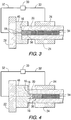
- FIG. 2 illustrates use of a SPS process - spark plasma sintering - to apply, cement, fuse, ceramic end caps to the ceramic composite utilizing a spark plasma sintering apparatus 11, here using primary and optional secondary electrodes, Also an inert gas such as He is inserted into the tubes to provide an internal backpressure of 345 to 3.450 kPA (50 psi to 500 psi) by well known processes, including drilling the end plugs, inserting the gas and refueling the end plug containing at least one ceramic composite tube 12, useful for holding nuclear fuel pellets in a nuclear reactor, disposed between at least one end cap 14 which end cap 14 engages the top 16 and interior 18 of the ceramic composite tube, and here also the circumferential exterior 20 of the ceramic composite tube.
- an inert gas such as He
- a paste may be applied to the end cap 14 or surfaces 16 and 18 to provide further sealing capability.
- At least two electrodes are attached to the end cap/tube, each electrode 22 adjacent to and in contact with the at least one end cap.
- the interface 26 between end caps and tube ends is most preferably polished to ensure better adhesion.
- the sintering apparatus 10 may be pressurized in vacuum or be ambient temperature and be in a furnace with a temperature 50°C up to 1,500°C. Also shown are pressure control/power supply means 30, power lines 32, fuel pellets 34 and pellet holding means, here spring 36.
- the end cap(s) are preferably SiC and the preferred space of end caps envelopment 38 is from 1.905 cm (0.75 inch) to 3.175 cm (1.25 inch).
- FIG. 3 using the same numerals as FIG. 2 , but using optional circumferential electrodes to seal one end at a time, describes a method where end cap(s) have a top and circumferential contact, and FIG. 4 describes a method where end cap(s) have a top and interior contact In these methods, there is at least one electrode 24 adjacent to and in contact with or surrounding the ceramic composite tube.
- FIG. 5 shows the method of this invention where 40, a tubular ceramic composite having interior and exterior tube walls and a circumferential axis is supplied; the ceramic composite has attached 42 to at least one end plug composition, preferably the same composition as the ceramic composite: an end cap 44 covering the top, interior and sides of the ceramic composite - a complete but complicated sealing end cap or an end cap 46 just covering the top and sides of the ceramic composite tube shown in FIG. 3 ; or an end cap 48 covering the top and interior of the ceramic composite tube shown in FIG. 4 .
- the end plug may be placed with or without paste on the end of the tube and electrodes applied to the tube and end plug(s) and all this applied into a spark plasma sintering means (11, 50) to hermetically seal the solidified end caps securely to the end of the ceramic composite 52.
- This invention provides a dramatic and probably futuristic method to commercially and practically produce a semi-flexible, controlled destruction, disaster capable, life saving sealed 60,96 - 548,64 cm (2-18 feet) long semi-flexible fuel rod tubes made of monolithic SiC and SiC fiber matrix, or other "ceramic composites" back filled with helium or other gas up to 3.450 kPa (500 psi).
- the fuel rod tube preferably has a duplex structure which consists of an inner monolithic SiC layer or multiple layers and an outer SiC/SiC preferably composite layer.
- the tube is sealed with end plugs at one or both ends made of SiC or other material.
- the tube and end plugs are joined together using electric field assisted sintering technology such as the spark plasma sintering method.
- the joining can be performed at an ambient condition or in vacuum or in a pressurized chamber or in a heated chamber.
- the sealed tube is gas tight and will not deform under a differential pressure up to 68.950 kPa (10.000 psi) at up to 1.500°C for at least six years.
- a "'Ceramic Composite” consisting of a 365,76 cm (12 foot) long extruded stoichiometric alpha phase nuclear reactor SiC tube, for containing nuclear fuel in a reactor, with an inner diameter of 0,8128 cm (0,32 inches) and a wall thickness of 0,0381 cm (0,015 inches) at a density of 95% of the SiC theoretical density, is wound with a 0,066 cm (0,026 inch) layer of SiC composite consisting of 6 layers of windings of stoichiometric beta phase SiC fibers and is infiltrated with beta phase stoichiometric SiC using chemical vapor infiltration to a net density for the composite of greater than 80% of the SiC theoretical density.
- This "Ceramic Composite” was sealed with extruded stoichiometric alpha phase end plugs with highly polished inner and upper tube seal faces as in Figure 4 , applied using plasma spark sintering as well known and previously defined in a chamber filled with helium at 2.585 kPa (375 psi) at ambient condition.
- the heating rate was 200°C/minute, with a bonding pressure of 5 MPa, a peak temperature of 2.100°C at the plug/ tube bonding interface, and with a hold time of from 5 minutes up to 60 minutes at the peak temperature.
Landscapes
- Engineering & Computer Science (AREA)
- Chemical & Material Sciences (AREA)
- Ceramic Engineering (AREA)
- Physics & Mathematics (AREA)
- Structural Engineering (AREA)
- Materials Engineering (AREA)
- Organic Chemistry (AREA)
- High Energy & Nuclear Physics (AREA)
- General Engineering & Computer Science (AREA)
- Plasma & Fusion (AREA)
- Metallurgy (AREA)
- Manufacturing & Machinery (AREA)
- Ceramic Products (AREA)
- Sealing Material Composition (AREA)
- Spark Plugs (AREA)
Claims (14)
- Verfahren zum hermetischen Abdichten eines Rohrs, das aus Keramikverbundstoff gebildet ist und zumindest eine Endkappe (14) aufweist, umfassend:(1) Bereitstellen eines Rohrs (40, 12), das aus einem Keramikverbundstoff gebildet ist, mit Rohrwänden, zumindest einem Ende, und einer Achse und zumindest einem Material für eine Endkappe (14);(2) Anbringen des zumindest einen Materials für eine Endkappe (14) an dem zumindest einen Ende des Rohrs (12), wobei die Endkappe (14) eine Außenseite (20) und eine Innenseite (18) aufweist;
gekennzeichnet durch:(3) Anbringen zumindest einer primären Elektrode (22) an der Außenseite (20) der zumindest einen Endkappe (14);(4) Anbringen zumindest einer zusätzlichen Elektrode (24) an der Außenseite (20) des Rohrs (40, 12);(5) Anlegen eines Stroms an zumindest die primäre Elektrode und die zusätzliche Elektrode und Verwenden eines Spark-Plasma-Sinterverfahrens, um einen rapiden Temperaturanstieg für 0,01 bis 6,0 Minuten an einer Schnittstelle zwischen dem Rohr (12) und der Endkappe (14) mit einer Rate von 200 °C/min bis zu 1.500 °C/min zu schaffen, wobei die Schnittstellentemperaturen von Umgebungstemperatur bis zu 2.500 °C betragen. - Verfahren nach Anspruch 1, wobei das Material für die Endkappen (14) ausgewählt ist aus der Gruppe bestehend aus Keramik, Karbid, Nitrid, Metall und Metalllegierungen.
- Verfahren nach Anspruch 1, wobei das Material für die Endkappen (14) auf SiC basiert.
- Verfahren nach Anspruch 1, wobei nach Schritt (1) die Schnittstellenenden der Endkappen (14) und des Rohrs (12) poliert werden.
- Verfahren nach einem der Ansprüche 1 bis 4, ferner umfassend in Schritt (5) das Halten einer Spitzentemperatur von bis zu 2.500 °C für eine Haltezeit von 0,01 bis 60 Minuten, bei Drücken von 0,001 MPa bis 50 MPa, um das Rohr (12) hermetisch mit der zumindest einen Endkappe (14) abzudichten.
- Verfahren nach einem der Ansprüche 1 bis 5, wobei die Endkappen (14) aus demselben Material wie der Keramikverbundstoff oder einem Vorläufer desselben bestehen.
- Verfahren nach einem der Ansprüche 1 bis 6, wobei die Betriebsparameter des Spark-Plasma-Sinterverfahrens den rapiden Temperaturanstieg mit einer Rate von 1.000 °C/min bis zu 1.500 °C/min für 1,0 bis 5,0 Minuten bewirken, um die Schnittstellentemperatur auf bis zu 2.500 °C und 0,001 bis 10 MPa zu erhöhen.
- Verfahren nach einem der Ansprüche 1 bis 7, wobei der rohrförmige Keramikverbundstoff und die Endkappen (14) aus SiC bestehen.
- Verfahren nach Anspruch 8, wobei der rohrförmige Keramikverbundstoff (40, 12) aus einem SiC-Verbundstoff besteht, der eine monolithische Schicht oder mehrere Schichten auf SiC-Basis auf der Innenseite und zumindest eine äußere Schicht aus Fasern auf SiC-Basis in einer Matrix auf SiC-Basis umfasst.
- Verfahren nach Anspruch 5, wobei ein Bindungsdruck von 4 bis 20 MPa nach Schritt (4) ausgeübt wird, mit einer Haltezeit von 5 Minuten bis 60 Minuten, die nach Schritt (5) angewendet wird.
- Verfahren nach Anspruch 5, wobei nach Schritt (1) oder Schritt (2) ein Inertgas in das Rohr (40, 12) eingebracht wird, mit einem Rückdruck von 345 kPa bis 3.450 kPa (50 psi bis 500 psi).
- Verfahren nach Anspruch 11, wobei das Inertgas Helium ist.
- Verfahren nach Anspruch 5, wobei zumindest Schritt (5) in einem Ofen mit einer Temperatur von etwa 50 °C bis 1.500 °C durchgeführt wird.
- Rohrförmiger Keramikverbundstoff (40, 12), der durch das Verfahren nach einem der Ansprüche 1 bis 13 hergestellt wird.
Applications Claiming Priority (2)
| Application Number | Priority Date | Filing Date | Title |
|---|---|---|---|
| US14/027,299 US9455053B2 (en) | 2013-09-16 | 2013-09-16 | SiC matrix fuel cladding tube with spark plasma sintered end plugs |
| PCT/US2014/051472 WO2015038286A1 (en) | 2013-09-16 | 2014-08-18 | A sic matrix fuel cladding tube with spark plasma sintered end plugs |
Publications (3)
| Publication Number | Publication Date |
|---|---|
| EP3047489A1 EP3047489A1 (de) | 2016-07-27 |
| EP3047489A4 EP3047489A4 (de) | 2017-04-19 |
| EP3047489B1 true EP3047489B1 (de) | 2019-07-31 |
Family
ID=52666148
Family Applications (1)
| Application Number | Title | Priority Date | Filing Date |
|---|---|---|---|
| EP14844134.8A Active EP3047489B1 (de) | 2013-09-16 | 2014-08-18 | Sic-matrix-brennstabhüllrohr mit spark-plasma-gesinterten endstopfen |
Country Status (7)
| Country | Link |
|---|---|
| US (2) | US9455053B2 (de) |
| EP (1) | EP3047489B1 (de) |
| JP (2) | JP2016531080A (de) |
| KR (1) | KR102333427B1 (de) |
| CN (1) | CN105706176B (de) |
| ES (1) | ES2748151T3 (de) |
| WO (1) | WO2015038286A1 (de) |
Families Citing this family (38)
| Publication number | Priority date | Publication date | Assignee | Title |
|---|---|---|---|---|
| US10593434B2 (en) * | 2014-03-12 | 2020-03-17 | Westinghouse Electric Company Llc | Ceramic reinforced zirconium alloy nuclear fuel cladding with intermediate oxidation resistant layer |
| US10734121B2 (en) * | 2014-03-12 | 2020-08-04 | Westinghouse Electric Company Llc | Double-sealed fuel rod end plug for ceramic-containing cladding |
| US10865151B2 (en) * | 2015-05-19 | 2020-12-15 | Basf Se | Gas-tight, heat-permeable multilayer ceramic composite tube |
| JP2017024923A (ja) * | 2015-07-16 | 2017-02-02 | イビデン株式会社 | セラミック複合材 |
| CN108139159A (zh) | 2015-10-14 | 2018-06-08 | 巴斯夫欧洲公司 | 含有复合纤维陶瓷的热渗透管 |
| EP3397763B1 (de) | 2015-12-28 | 2020-10-28 | Koninklijke Philips N.V. | Nukleinsäurenreinigungssystem unter verwendung einer einzigen wasch- und eluierungspufferlösung |
| US10872701B2 (en) * | 2016-06-10 | 2020-12-22 | Westinghouse Electric Company Llc | Zirconium-coated silicon carbide fuel cladding for accident tolerant fuel application |
| US10446276B2 (en) | 2016-06-21 | 2019-10-15 | Westinghouse Electric Company Llc | Method of manufacturing a SiC composite fuel cladding with inner Zr alloy liner |
| WO2018071066A2 (en) * | 2016-06-22 | 2018-04-19 | Westinghouse Electric Company Llc | Nuclear fuel rod |
| US10614923B2 (en) | 2016-07-19 | 2020-04-07 | Battelle Energy Alliance, Llc | Methods of forming structures and fissile fuel materials by additive manufacturing |
| RU2720579C1 (ru) * | 2016-08-08 | 2020-05-12 | Дженерал Атомикс | Разработанные sic-sic композит и монолитные слоистые sic структуры |
| GB2553090A (en) * | 2016-08-16 | 2018-02-28 | Rolls Royce Power Eng Plc | Method of manufacture |
| US10899671B2 (en) | 2016-08-24 | 2021-01-26 | Westinghouse Electric Company Llc | Process for manufacturing SiC composite ceramics |
| US11031145B2 (en) * | 2017-03-06 | 2021-06-08 | Westinghouse Electric Company Llc | Method of manufacturing a reinforced nuclear fuel cladding using an intermediate thermal deposition layer |
| US11014265B2 (en) | 2017-03-20 | 2021-05-25 | Battelle Energy Alliance, Llc | Methods and apparatus for additively manufacturing structures using in situ formed additive manufacturing materials |
| CN106971764B (zh) * | 2017-04-13 | 2019-04-30 | 中国工程物理研究院材料研究所 | 一种惰性基弥散燃料芯块的快速制备工艺 |
| JP6917770B2 (ja) | 2017-05-15 | 2021-08-11 | 株式会社東芝 | 長繊維強化炭化ケイ素部材、その製造方法、および、原子炉構造部材 |
| US10515728B2 (en) * | 2017-09-18 | 2019-12-24 | Westinghouse Electric Company Llc | High temperature ceramic nuclear fuel system for light water reactors and lead fast reactors |
| US20190108922A1 (en) * | 2017-10-06 | 2019-04-11 | Westinghouse Electric Company, Llc | Removable mandrel for automating process to manufacture ceramic composite nuclear fuel cladding tubes |
| KR102661803B1 (ko) | 2017-10-19 | 2024-04-26 | 제너럴 아토믹스 | 가압 세라믹 구조물의 접합 및 밀봉 |
| CN110085338B (zh) * | 2018-01-25 | 2022-09-20 | 国家电投集团科学技术研究院有限公司 | UO2/Cr复合燃料芯块的制备方法以及制备装置 |
| US11049622B2 (en) | 2018-02-13 | 2021-06-29 | Westinghouse Electric Company Llc | Method to pressurize sic fuel cladding tube before end plug sealing by pressurization pushing spring loaded end plug |
| US11404175B2 (en) | 2018-07-16 | 2022-08-02 | Westinghouse Electric Company Llc | Silicon carbide reinforced zirconium based cladding |
| CN109326363B (zh) * | 2018-09-29 | 2020-12-29 | 中广核研究院有限公司 | 弥散型燃料芯块及其制备方法、燃料棒 |
| CN109574691B (zh) * | 2018-12-06 | 2021-08-03 | 核工业第八研究所 | 一种碳化硅陶瓷包壳元件端塞的制作方法 |
| KR20210137088A (ko) | 2019-03-07 | 2021-11-17 | 웨스팅하우스 일렉트릭 컴퍼니 엘엘씨 | 자가 치유 액체 펠릿-클래딩 간극 열 전달 필러 |
| US11935662B2 (en) * | 2019-07-02 | 2024-03-19 | Westinghouse Electric Company Llc | Elongate SiC fuel elements |
| JP7350254B2 (ja) * | 2019-08-05 | 2023-09-26 | 国立大学法人京都大学 | 端栓が接合された燃料棒 |
| CN111951991A (zh) * | 2020-06-15 | 2020-11-17 | 西安交通大学 | 一种基于3d打印的棒状核燃料元件及其密封成形方法 |
| RU2762100C1 (ru) * | 2020-11-10 | 2021-12-15 | Акционерное общество "Высокотехнологический научно-исследовательский институт неорганических материалов имени академика А.А. Бочвара" (АО "ВНИИНМ") | Торцевая заглушка для герметизации композиционной трубчатой керамической оболочки тепловыделяющего элемента ядерного реактора (варианты) и способ ее изготовления (варианты) |
| RU2762000C1 (ru) * | 2020-11-10 | 2021-12-14 | Акционерное общество "Высокотехнологический научно-исследовательский институт неорганических материалов имени академика А.А. Бочвара" (АО "ВНИИНМ") | Способ изготовления керамической многослойной трубки для оболочки тепловыделяющего элемента ядерной энергетической установки |
| CN112570832B (zh) * | 2020-11-12 | 2021-12-14 | 岭东核电有限公司 | 碳化硅包壳及其钎焊连接方法 |
| CN112851357A (zh) * | 2020-12-31 | 2021-05-28 | 中核北方核燃料元件有限公司 | 一种SiC复合材料包壳管的端塞制备方法 |
| US20230132157A1 (en) * | 2021-10-21 | 2023-04-27 | Westinghouse Electric Company Llc | Annular nuclear fuel rod |
| CN114944234B (zh) * | 2022-04-27 | 2024-09-06 | 中国原子能科学研究院 | 一种端塞包壳一体化环形燃料棒及燃料组件 |
| WO2024138118A1 (en) * | 2022-12-22 | 2024-06-27 | Carbon Sic Technologies, Inc. | Methods, systems, and devices for manufacturing ceramic composites |
| CN116621584B (zh) * | 2023-06-21 | 2024-11-15 | 中国航发北京航空材料研究院 | 一种微片层结构增强碳化硅陶瓷复合材料及其制备方法 |
| CN119601270B (zh) * | 2024-10-24 | 2025-09-26 | 中国核动力研究设计院 | 燃料芯块的制备方法和U3Si2燃料芯块 |
Family Cites Families (22)
| Publication number | Priority date | Publication date | Assignee | Title |
|---|---|---|---|---|
| US3427222A (en) | 1965-10-15 | 1969-02-11 | Westinghouse Electric Corp | Nuclear fuel elements |
| US6697448B1 (en) | 1966-11-16 | 2004-02-24 | The United States Of America As Represented By The United States Department Of Energy | Neutronic fuel element fabrication |
| BE787697A (fr) * | 1971-08-20 | 1973-02-19 | Westinghouse Electric Corp | Methodes et appareils de soudage |
| US4925608A (en) | 1988-09-27 | 1990-05-15 | Norton Company | Joining of SiC parts by polishing and hipping |
| JP2778146B2 (ja) * | 1989-08-25 | 1998-07-23 | 株式会社ダイヘン | セラミックス発熱体の通電端子部材の電気接合方法 |
| US5075075A (en) | 1990-01-16 | 1991-12-24 | Westinghouse Electric Corp. | Nuclear reactor core having nuclear fuel and composite burnable absorber arranged for power peaking and moderator temperature coefficient control |
| US5182077A (en) | 1991-04-15 | 1993-01-26 | Gamma Engineering Corporation | Water cooled nuclear reactor and fuel elements therefor |
| JP2642573B2 (ja) | 1991-12-27 | 1997-08-20 | 日本碍子株式会社 | SiC質焼結体 |
| JPH07508703A (ja) | 1992-06-12 | 1995-09-28 | ミネソタ・マイニング・アンド・マニュファクチュアリング・カンパニー | モノリシックセラミック/繊維強化セラミック複合材料 |
| US5375756A (en) * | 1993-03-31 | 1994-12-27 | General Electric Company | Apparatus for assembling and welding final end plugs to nuclear fuel-containing cladding tubes and inspecting the welds, all on an automated basis |
| US5447683A (en) | 1993-11-08 | 1995-09-05 | General Atomics | Braze for silicon carbide bodies |
| JPH08122472A (ja) | 1994-10-21 | 1996-05-17 | Mitsubishi Nuclear Fuel Co Ltd | 管の端栓及びその溶接方法 |
| FR2749787B1 (fr) | 1996-06-12 | 1998-07-24 | Commissariat Energie Atomique | Procede d'assemblage a l'aide d'un joint epais de pieces en materiaux a base de sic par brasage refractaire et joint refractaire et epais ainsi obtenu |
| JP3143086B2 (ja) | 1997-10-14 | 2001-03-07 | 核燃料サイクル開発機構 | SiC複合材料スリーブおよびその製造方法 |
| FR2806405B1 (fr) | 2000-03-14 | 2002-10-11 | Commissariat Energie Atomique | Procede d'assemblage de pieces en materiaux a base de sic par brasage refractaire non reactif, composition de brasure, et joint et assemblage refractaires obtenus par ce procede |
| US20060039524A1 (en) | 2004-06-07 | 2006-02-23 | Herbert Feinroth | Multi-layered ceramic tube for fuel containment barrier and other applications in nuclear and fossil power plants |
| US7139360B2 (en) | 2004-10-14 | 2006-11-21 | Westinghouse Electric Co. Llc | Use of boron or enriched boron 10 in UO2 |
| US7700202B2 (en) | 2006-02-16 | 2010-04-20 | Alliant Techsystems Inc. | Precursor formulation of a silicon carbide material |
| FR2906242B1 (fr) * | 2006-09-27 | 2009-01-16 | Commissariat Energie Atomique | Procede d'assemblage de pieces en ceramique refractaire par frittage a chaud avec champ electrique pulse ("sps") |
| FR2957542B1 (fr) | 2010-03-16 | 2012-05-11 | Commissariat Energie Atomique | Procede d'assemblage de pieces en materiaux a base de sic par brasage non-reactif, compositions de brasure, et joint et assemblage obtenus par ce procede. |
| JP5677184B2 (ja) * | 2011-04-28 | 2015-02-25 | 株式会社東芝 | 燃料被覆管接合体およびその製造方法 |
| US20130010915A1 (en) | 2011-07-08 | 2013-01-10 | Battelle Energy Alliance, Llc | Reactor fuel elements and related methods |
-
2013
- 2013-09-16 US US14/027,299 patent/US9455053B2/en active Active
-
2014
- 2014-08-18 JP JP2016541982A patent/JP2016531080A/ja active Pending
- 2014-08-18 WO PCT/US2014/051472 patent/WO2015038286A1/en not_active Ceased
- 2014-08-18 KR KR1020167009127A patent/KR102333427B1/ko active Active
- 2014-08-18 EP EP14844134.8A patent/EP3047489B1/de active Active
- 2014-08-18 CN CN201480050687.8A patent/CN105706176B/zh not_active Expired - Fee Related
- 2014-08-18 ES ES14844134T patent/ES2748151T3/es active Active
-
2016
- 2016-08-01 US US15/225,127 patent/US10062458B2/en active Active
-
2018
- 2018-08-28 JP JP2018159684A patent/JP6702644B2/ja not_active Expired - Fee Related
Non-Patent Citations (1)
| Title |
|---|
| None * |
Also Published As
| Publication number | Publication date |
|---|---|
| JP2016531080A (ja) | 2016-10-06 |
| US20150078505A1 (en) | 2015-03-19 |
| CN105706176A (zh) | 2016-06-22 |
| KR102333427B1 (ko) | 2021-12-01 |
| US20160358673A1 (en) | 2016-12-08 |
| JP2019023157A (ja) | 2019-02-14 |
| WO2015038286A1 (en) | 2015-03-19 |
| US9455053B2 (en) | 2016-09-27 |
| EP3047489A4 (de) | 2017-04-19 |
| EP3047489A1 (de) | 2016-07-27 |
| JP6702644B2 (ja) | 2020-06-03 |
| ES2748151T3 (es) | 2020-03-13 |
| US10062458B2 (en) | 2018-08-28 |
| CN105706176B (zh) | 2017-12-15 |
| KR20160068770A (ko) | 2016-06-15 |
Similar Documents
| Publication | Publication Date | Title |
|---|---|---|
| EP3047489B1 (de) | Sic-matrix-brennstabhüllrohr mit spark-plasma-gesinterten endstopfen | |
| EP3117440B1 (de) | Doppelt abgedichteter brennstabendstopfen für keramikhaltige verkleidung | |
| KR102572043B1 (ko) | 고온 기밀성 및 사고 내성을 갖는 다층 복합물 연료 클래드 시스템 | |
| US9548139B2 (en) | Multilayer tube in ceramic matrix composite material, resulting nuclear fuel cladding and associated manufacturing processes | |
| EP3117439B1 (de) | Keramikverstärkte zirkoniumlegierungskernbrennelementverkleidung mit oxidationsbeständiger zwischenschicht | |
| EP1774534A2 (de) | Mehrschichtige keramikröhre für die sperrschicht von brennstoffhüllen und andere anwendungen für kern- und fossilkraftwerke | |
| US20160049211A1 (en) | Silicon carbide multilayered cladding and nuclear reactor fuel element for use in water-cooled nuclear power reactors | |
| WO2014199459A1 (ja) | 管状体および管状体の製造方法 | |
| JP2022153525A (ja) | 軽水炉および鉛高速炉向け高温セラミック原子燃料システム |
Legal Events
| Date | Code | Title | Description |
|---|---|---|---|
| PUAI | Public reference made under article 153(3) epc to a published international application that has entered the european phase |
Free format text: ORIGINAL CODE: 0009012 |
|
| 17P | Request for examination filed |
Effective date: 20160208 |
|
| AK | Designated contracting states |
Kind code of ref document: A1 Designated state(s): AL AT BE BG CH CY CZ DE DK EE ES FI FR GB GR HR HU IE IS IT LI LT LU LV MC MK MT NL NO PL PT RO RS SE SI SK SM TR |
|
| AX | Request for extension of the european patent |
Extension state: BA ME |
|
| RAP1 | Party data changed (applicant data changed or rights of an application transferred) |
Owner name: WESTINGHOUSE ELECTRIC COMPANY LLC Owner name: KABUSHIKI KAISHA TOSHIBA |
|
| DAX | Request for extension of the european patent (deleted) | ||
| A4 | Supplementary search report drawn up and despatched |
Effective date: 20170322 |
|
| RIC1 | Information provided on ipc code assigned before grant |
Ipc: G21C 21/02 20060101ALI20170316BHEP Ipc: G21C 3/07 20060101ALI20170316BHEP Ipc: G21C 3/06 20060101ALI20170316BHEP Ipc: G21C 3/10 20060101AFI20170316BHEP |
|
| STAA | Information on the status of an ep patent application or granted ep patent |
Free format text: STATUS: EXAMINATION IS IN PROGRESS |
|
| 17Q | First examination report despatched |
Effective date: 20180207 |
|
| RAP1 | Party data changed (applicant data changed or rights of an application transferred) |
Owner name: TOSHIBA ENERGY SYSTEMS & SOLUTIONS CORPORATION Owner name: WESTINGHOUSE ELECTRIC COMPANY LLC |
|
| GRAP | Despatch of communication of intention to grant a patent |
Free format text: ORIGINAL CODE: EPIDOSNIGR1 |
|
| STAA | Information on the status of an ep patent application or granted ep patent |
Free format text: STATUS: GRANT OF PATENT IS INTENDED |
|
| INTG | Intention to grant announced |
Effective date: 20190510 |
|
| GRAS | Grant fee paid |
Free format text: ORIGINAL CODE: EPIDOSNIGR3 |
|
| GRAA | (expected) grant |
Free format text: ORIGINAL CODE: 0009210 |
|
| STAA | Information on the status of an ep patent application or granted ep patent |
Free format text: STATUS: THE PATENT HAS BEEN GRANTED |
|
| AK | Designated contracting states |
Kind code of ref document: B1 Designated state(s): AL AT BE BG CH CY CZ DE DK EE ES FI FR GB GR HR HU IE IS IT LI LT LU LV MC MK MT NL NO PL PT RO RS SE SI SK SM TR |
|
| REG | Reference to a national code |
Ref country code: CH Ref legal event code: EP Ref country code: GB Ref legal event code: FG4D |
|
| REG | Reference to a national code |
Ref country code: AT Ref legal event code: REF Ref document number: 1161780 Country of ref document: AT Kind code of ref document: T Effective date: 20190815 |
|
| REG | Reference to a national code |
Ref country code: IE Ref legal event code: FG4D |
|
| REG | Reference to a national code |
Ref country code: DE Ref legal event code: R096 Ref document number: 602014051008 Country of ref document: DE |
|
| REG | Reference to a national code |
Ref country code: SE Ref legal event code: TRGR |
|
| REG | Reference to a national code |
Ref country code: NL Ref legal event code: MP Effective date: 20190731 |
|
| REG | Reference to a national code |
Ref country code: LT Ref legal event code: MG4D |
|
| REG | Reference to a national code |
Ref country code: AT Ref legal event code: MK05 Ref document number: 1161780 Country of ref document: AT Kind code of ref document: T Effective date: 20190731 |
|
| PG25 | Lapsed in a contracting state [announced via postgrant information from national office to epo] |
Ref country code: LT Free format text: LAPSE BECAUSE OF FAILURE TO SUBMIT A TRANSLATION OF THE DESCRIPTION OR TO PAY THE FEE WITHIN THE PRESCRIBED TIME-LIMIT Effective date: 20190731 Ref country code: HR Free format text: LAPSE BECAUSE OF FAILURE TO SUBMIT A TRANSLATION OF THE DESCRIPTION OR TO PAY THE FEE WITHIN THE PRESCRIBED TIME-LIMIT Effective date: 20190731 Ref country code: FI Free format text: LAPSE BECAUSE OF FAILURE TO SUBMIT A TRANSLATION OF THE DESCRIPTION OR TO PAY THE FEE WITHIN THE PRESCRIBED TIME-LIMIT Effective date: 20190731 Ref country code: NO Free format text: LAPSE BECAUSE OF FAILURE TO SUBMIT A TRANSLATION OF THE DESCRIPTION OR TO PAY THE FEE WITHIN THE PRESCRIBED TIME-LIMIT Effective date: 20191031 Ref country code: BG Free format text: LAPSE BECAUSE OF FAILURE TO SUBMIT A TRANSLATION OF THE DESCRIPTION OR TO PAY THE FEE WITHIN THE PRESCRIBED TIME-LIMIT Effective date: 20191031 Ref country code: NL Free format text: LAPSE BECAUSE OF FAILURE TO SUBMIT A TRANSLATION OF THE DESCRIPTION OR TO PAY THE FEE WITHIN THE PRESCRIBED TIME-LIMIT Effective date: 20190731 Ref country code: AT Free format text: LAPSE BECAUSE OF FAILURE TO SUBMIT A TRANSLATION OF THE DESCRIPTION OR TO PAY THE FEE WITHIN THE PRESCRIBED TIME-LIMIT Effective date: 20190731 Ref country code: PT Free format text: LAPSE BECAUSE OF FAILURE TO SUBMIT A TRANSLATION OF THE DESCRIPTION OR TO PAY THE FEE WITHIN THE PRESCRIBED TIME-LIMIT Effective date: 20191202 |
|
| PG25 | Lapsed in a contracting state [announced via postgrant information from national office to epo] |
Ref country code: AL Free format text: LAPSE BECAUSE OF FAILURE TO SUBMIT A TRANSLATION OF THE DESCRIPTION OR TO PAY THE FEE WITHIN THE PRESCRIBED TIME-LIMIT Effective date: 20190731 Ref country code: GR Free format text: LAPSE BECAUSE OF FAILURE TO SUBMIT A TRANSLATION OF THE DESCRIPTION OR TO PAY THE FEE WITHIN THE PRESCRIBED TIME-LIMIT Effective date: 20191101 Ref country code: RS Free format text: LAPSE BECAUSE OF FAILURE TO SUBMIT A TRANSLATION OF THE DESCRIPTION OR TO PAY THE FEE WITHIN THE PRESCRIBED TIME-LIMIT Effective date: 20190731 Ref country code: LV Free format text: LAPSE BECAUSE OF FAILURE TO SUBMIT A TRANSLATION OF THE DESCRIPTION OR TO PAY THE FEE WITHIN THE PRESCRIBED TIME-LIMIT Effective date: 20190731 Ref country code: IS Free format text: LAPSE BECAUSE OF FAILURE TO SUBMIT A TRANSLATION OF THE DESCRIPTION OR TO PAY THE FEE WITHIN THE PRESCRIBED TIME-LIMIT Effective date: 20191130 |
|
| REG | Reference to a national code |
Ref country code: DE Ref legal event code: R119 Ref document number: 602014051008 Country of ref document: DE |
|
| REG | Reference to a national code |
Ref country code: ES Ref legal event code: FG2A Ref document number: 2748151 Country of ref document: ES Kind code of ref document: T3 Effective date: 20200313 |
|
| PG25 | Lapsed in a contracting state [announced via postgrant information from national office to epo] |
Ref country code: TR Free format text: LAPSE BECAUSE OF FAILURE TO SUBMIT A TRANSLATION OF THE DESCRIPTION OR TO PAY THE FEE WITHIN THE PRESCRIBED TIME-LIMIT Effective date: 20190731 |
|
| PG25 | Lapsed in a contracting state [announced via postgrant information from national office to epo] |
Ref country code: IT Free format text: LAPSE BECAUSE OF FAILURE TO SUBMIT A TRANSLATION OF THE DESCRIPTION OR TO PAY THE FEE WITHIN THE PRESCRIBED TIME-LIMIT Effective date: 20190731 Ref country code: RO Free format text: LAPSE BECAUSE OF FAILURE TO SUBMIT A TRANSLATION OF THE DESCRIPTION OR TO PAY THE FEE WITHIN THE PRESCRIBED TIME-LIMIT Effective date: 20190731 Ref country code: DK Free format text: LAPSE BECAUSE OF FAILURE TO SUBMIT A TRANSLATION OF THE DESCRIPTION OR TO PAY THE FEE WITHIN THE PRESCRIBED TIME-LIMIT Effective date: 20190731 Ref country code: PL Free format text: LAPSE BECAUSE OF FAILURE TO SUBMIT A TRANSLATION OF THE DESCRIPTION OR TO PAY THE FEE WITHIN THE PRESCRIBED TIME-LIMIT Effective date: 20190731 Ref country code: EE Free format text: LAPSE BECAUSE OF FAILURE TO SUBMIT A TRANSLATION OF THE DESCRIPTION OR TO PAY THE FEE WITHIN THE PRESCRIBED TIME-LIMIT Effective date: 20190731 |
|
| PG25 | Lapsed in a contracting state [announced via postgrant information from national office to epo] |
Ref country code: MC Free format text: LAPSE BECAUSE OF FAILURE TO SUBMIT A TRANSLATION OF THE DESCRIPTION OR TO PAY THE FEE WITHIN THE PRESCRIBED TIME-LIMIT Effective date: 20190731 Ref country code: CZ Free format text: LAPSE BECAUSE OF FAILURE TO SUBMIT A TRANSLATION OF THE DESCRIPTION OR TO PAY THE FEE WITHIN THE PRESCRIBED TIME-LIMIT Effective date: 20190731 Ref country code: SM Free format text: LAPSE BECAUSE OF FAILURE TO SUBMIT A TRANSLATION OF THE DESCRIPTION OR TO PAY THE FEE WITHIN THE PRESCRIBED TIME-LIMIT Effective date: 20190731 Ref country code: CH Free format text: LAPSE BECAUSE OF NON-PAYMENT OF DUE FEES Effective date: 20190831 Ref country code: LU Free format text: LAPSE BECAUSE OF NON-PAYMENT OF DUE FEES Effective date: 20190818 Ref country code: SK Free format text: LAPSE BECAUSE OF FAILURE TO SUBMIT A TRANSLATION OF THE DESCRIPTION OR TO PAY THE FEE WITHIN THE PRESCRIBED TIME-LIMIT Effective date: 20190731 Ref country code: LI Free format text: LAPSE BECAUSE OF NON-PAYMENT OF DUE FEES Effective date: 20190831 Ref country code: IS Free format text: LAPSE BECAUSE OF FAILURE TO SUBMIT A TRANSLATION OF THE DESCRIPTION OR TO PAY THE FEE WITHIN THE PRESCRIBED TIME-LIMIT Effective date: 20200224 |
|
| REG | Reference to a national code |
Ref country code: BE Ref legal event code: MM Effective date: 20190831 |
|
| PLBE | No opposition filed within time limit |
Free format text: ORIGINAL CODE: 0009261 |
|
| STAA | Information on the status of an ep patent application or granted ep patent |
Free format text: STATUS: NO OPPOSITION FILED WITHIN TIME LIMIT |
|
| PG2D | Information on lapse in contracting state deleted |
Ref country code: IS |
|
| PG25 | Lapsed in a contracting state [announced via postgrant information from national office to epo] |
Ref country code: DE Free format text: LAPSE BECAUSE OF NON-PAYMENT OF DUE FEES Effective date: 20200303 Ref country code: IE Free format text: LAPSE BECAUSE OF NON-PAYMENT OF DUE FEES Effective date: 20190818 Ref country code: IS Free format text: LAPSE BECAUSE OF FAILURE TO SUBMIT A TRANSLATION OF THE DESCRIPTION OR TO PAY THE FEE WITHIN THE PRESCRIBED TIME-LIMIT Effective date: 20191030 |
|
| 26N | No opposition filed |
Effective date: 20200603 |
|
| PG25 | Lapsed in a contracting state [announced via postgrant information from national office to epo] |
Ref country code: BE Free format text: LAPSE BECAUSE OF NON-PAYMENT OF DUE FEES Effective date: 20190831 Ref country code: SI Free format text: LAPSE BECAUSE OF FAILURE TO SUBMIT A TRANSLATION OF THE DESCRIPTION OR TO PAY THE FEE WITHIN THE PRESCRIBED TIME-LIMIT Effective date: 20190731 |
|
| PG25 | Lapsed in a contracting state [announced via postgrant information from national office to epo] |
Ref country code: CY Free format text: LAPSE BECAUSE OF FAILURE TO SUBMIT A TRANSLATION OF THE DESCRIPTION OR TO PAY THE FEE WITHIN THE PRESCRIBED TIME-LIMIT Effective date: 20190731 |
|
| PG25 | Lapsed in a contracting state [announced via postgrant information from national office to epo] |
Ref country code: MT Free format text: LAPSE BECAUSE OF FAILURE TO SUBMIT A TRANSLATION OF THE DESCRIPTION OR TO PAY THE FEE WITHIN THE PRESCRIBED TIME-LIMIT Effective date: 20190731 Ref country code: HU Free format text: LAPSE BECAUSE OF FAILURE TO SUBMIT A TRANSLATION OF THE DESCRIPTION OR TO PAY THE FEE WITHIN THE PRESCRIBED TIME-LIMIT; INVALID AB INITIO Effective date: 20140818 |
|
| PG25 | Lapsed in a contracting state [announced via postgrant information from national office to epo] |
Ref country code: MK Free format text: LAPSE BECAUSE OF FAILURE TO SUBMIT A TRANSLATION OF THE DESCRIPTION OR TO PAY THE FEE WITHIN THE PRESCRIBED TIME-LIMIT Effective date: 20190731 |
|
| PGFP | Annual fee paid to national office [announced via postgrant information from national office to epo] |
Ref country code: ES Payment date: 20250911 Year of fee payment: 12 |
|
| PGFP | Annual fee paid to national office [announced via postgrant information from national office to epo] |
Ref country code: GB Payment date: 20250821 Year of fee payment: 12 |
|
| PGFP | Annual fee paid to national office [announced via postgrant information from national office to epo] |
Ref country code: FR Payment date: 20250818 Year of fee payment: 12 |
|
| PGFP | Annual fee paid to national office [announced via postgrant information from national office to epo] |
Ref country code: SE Payment date: 20250812 Year of fee payment: 12 |