EP3047322B1 - Automatic optical fiber inserting apparatus and fiber inserting method - Google Patents
Automatic optical fiber inserting apparatus and fiber inserting method Download PDFInfo
- Publication number
- EP3047322B1 EP3047322B1 EP14759345.3A EP14759345A EP3047322B1 EP 3047322 B1 EP3047322 B1 EP 3047322B1 EP 14759345 A EP14759345 A EP 14759345A EP 3047322 B1 EP3047322 B1 EP 3047322B1
- Authority
- EP
- European Patent Office
- Prior art keywords
- fiber
- bare
- clamp
- chamber
- fibers
- Prior art date
- Legal status (The legal status is an assumption and is not a legal conclusion. Google has not performed a legal analysis and makes no representation as to the accuracy of the status listed.)
- Not-in-force
Links
- 239000000835 fiber Substances 0.000 title claims description 451
- 238000000034 method Methods 0.000 title claims description 30
- 239000013307 optical fiber Substances 0.000 title description 7
- 230000003287 optical effect Effects 0.000 claims description 26
- 230000008569 process Effects 0.000 claims description 12
- 238000004891 communication Methods 0.000 claims description 6
- 230000007246 mechanism Effects 0.000 description 34
- 238000003780 insertion Methods 0.000 description 14
- 230000037431 insertion Effects 0.000 description 14
- 238000001179 sorption measurement Methods 0.000 description 6
- 239000000919 ceramic Substances 0.000 description 4
- 230000009471 action Effects 0.000 description 3
- 238000004519 manufacturing process Methods 0.000 description 3
- 238000003860 storage Methods 0.000 description 3
- 238000005520 cutting process Methods 0.000 description 2
- 230000014759 maintenance of location Effects 0.000 description 2
- 239000002184 metal Substances 0.000 description 2
- 230000000007 visual effect Effects 0.000 description 2
- 238000005452 bending Methods 0.000 description 1
- 230000008901 benefit Effects 0.000 description 1
- 230000008859 change Effects 0.000 description 1
- 230000007547 defect Effects 0.000 description 1
- 238000001514 detection method Methods 0.000 description 1
- 238000003384 imaging method Methods 0.000 description 1
- 238000012986 modification Methods 0.000 description 1
- 230000004048 modification Effects 0.000 description 1
Images


Classifications
-
- G—PHYSICS
- G02—OPTICS
- G02B—OPTICAL ELEMENTS, SYSTEMS OR APPARATUS
- G02B6/00—Light guides; Structural details of arrangements comprising light guides and other optical elements, e.g. couplings
- G02B6/24—Coupling light guides
- G02B6/36—Mechanical coupling means
- G02B6/38—Mechanical coupling means having fibre to fibre mating means
- G02B6/3807—Dismountable connectors, i.e. comprising plugs
- G02B6/3833—Details of mounting fibres in ferrules; Assembly methods; Manufacture
- G02B6/3834—Means for centering or aligning the light guide within the ferrule
- G02B6/3835—Means for centering or aligning the light guide within the ferrule using discs, bushings or the like
- G02B6/3837—Means for centering or aligning the light guide within the ferrule using discs, bushings or the like forwarding or threading methods of light guides into apertures of ferrule centering means
-
- G—PHYSICS
- G02—OPTICS
- G02B—OPTICAL ELEMENTS, SYSTEMS OR APPARATUS
- G02B6/00—Light guides; Structural details of arrangements comprising light guides and other optical elements, e.g. couplings
- G02B6/24—Coupling light guides
- G02B6/36—Mechanical coupling means
- G02B6/38—Mechanical coupling means having fibre to fibre mating means
- G02B6/3807—Dismountable connectors, i.e. comprising plugs
- G02B6/3833—Details of mounting fibres in ferrules; Assembly methods; Manufacture
- G02B6/3834—Means for centering or aligning the light guide within the ferrule
- G02B6/3843—Means for centering or aligning the light guide within the ferrule with auxiliary facilities for movably aligning or adjusting the fibre within its ferrule, e.g. measuring position or eccentricity
-
- G—PHYSICS
- G02—OPTICS
- G02B—OPTICAL ELEMENTS, SYSTEMS OR APPARATUS
- G02B6/00—Light guides; Structural details of arrangements comprising light guides and other optical elements, e.g. couplings
- G02B6/24—Coupling light guides
- G02B6/36—Mechanical coupling means
- G02B6/38—Mechanical coupling means having fibre to fibre mating means
- G02B6/3807—Dismountable connectors, i.e. comprising plugs
- G02B6/3873—Connectors using guide surfaces for aligning ferrule ends, e.g. tubes, sleeves, V-grooves, rods, pins, balls
- G02B6/3885—Multicore or multichannel optical connectors, i.e. one single ferrule containing more than one fibre, e.g. ribbon type
-
- G—PHYSICS
- G02—OPTICS
- G02B—OPTICAL ELEMENTS, SYSTEMS OR APPARATUS
- G02B6/00—Light guides; Structural details of arrangements comprising light guides and other optical elements, e.g. couplings
- G02B6/24—Coupling light guides
- G02B6/36—Mechanical coupling means
- G02B6/38—Mechanical coupling means having fibre to fibre mating means
- G02B6/3807—Dismountable connectors, i.e. comprising plugs
- G02B6/3898—Tools, e.g. handheld; Tuning wrenches; Jigs used with connectors, e.g. for extracting, removing or inserting in a panel, for engaging or coupling connectors, for assembling or disassembling components within the connector, for applying clips to hold two connectors together or for crimping
Definitions
- Embodiments of the present invention generally relate to fiber inserting, in particular to a fiber inserting apparatus and a fiber inserting method.
- US 4,944,079 discloses a machine for connecting an end of an optical fiber cable to an optical fiber connector.
- the machine comprises a stripping mechanism that strips an end of a jacket from an end of the optical fiber cable to expose an end of a fiber core, a connector-connecting mechanism which inserts the stripped end of the optical fiber cable into a hole in the optical fiber connector and connects the cable with the connector, a core-cutting mechanism which cuts the length of the fiber core protruding from the front end of the connector leaving a tiny length of protruding fiber core, and a core-finishing mechanism which finishes the end surface of the protruding tiny length of fiber core.
- US 2003/0128952A1 discloses an optical component carrier apparatus adapted to hold a plurality of fiber optic cables and optical components.
- the carrier apparatus generally includes a body having a top, bottom, and sidewall members that cooperatively define an optical component storage region.
- a plurality of component storage apparatuses disposed within the component storage region are provided, and at least one clamp apparatus coupled to at least one of the sidewall members and adapted to grip at least one of the optical components and the plurality of fiber optic cables is provided.
- US 4,464,817 discloses an optical waveguide terminating apparatus.
- the apparatus applies a pair of plug members of the type having metal retention sleeves therein to cut and strip the ends of a jacketed optical waveguide cable.
- Plug members are delivered to a insertion station attached to a metal carrier strip and are clamped securely between an anvil and an upper clamp which move together vertically under the action of followers riding in cam slots in a moving cam block, which also determines movement of other components.
- Cable is positioned relative to insertion station by aligning exposed fibers in narrow channels in top of shear bar which drops to remove carrier strip and positions cable guide channels in cable feed path.
- a pair of cam actuated jaws grip the cable and advance the ends toward the terminating station; the guides drop away during this advance to permit the jaws to fully insert the cable ends in the plug member. Cables are pulled back to seat them on lances in the retention sleeves and a hot cutting blade shears the optical fiber protruding beyond the plug members flush therewith.
- the present invention has been made to overcome or alleviate at least one aspect of the above mentioned disadvantages.
- the straightening section may comprise a guide guiding the chamber in the first direction.
- a length of each elongated slots in the fiber inserting direction is equal to or larger than that of the bare fiber exposed from the fiber clamp.
- the straightening section is fixed in position with respect to the fiber clamp.
- the fiber inserting apparatus may further comprise a second drive driving the chamber to move backwards and forwards in the fiber inserting direction.
- the second drive is a piston drive or a screw drive.
- the fiber inserting apparatus may comprise: a chamber support; a supporting frame; a seat disposed on the supporting frame; two screws driven synchronously, each of which passing through threaded holes in the chamber support with both ends of each of the screws being supported by the seat, and the chamber support moving in axial directions of the screws parallel to the fiber inserting direction based on rotations of the screws; a hydraulic cylinder or an air cylinder disposed on the chamber support, one end of a piston rod of which being connected to the chamber, wherein the first drive comprises the hydraulic cylinder or the air cylinder and the piston rod, and the second drive comprises the two screws.
- the table is provided with an opening between the fiber clamp and the ferrule clamp extending in the fiber inserting direction, and at least one part of the supporting frame is positioned in the opening.
- the supporting frame is fixed in position with respect to the fiber clamp, and the fiber clamp is adapted to move relative to the ferrule clamp.
- the chamber is provided with guide rods
- the chamber support is provided with guide holes in which the guide rods are positioned when the chamber moves based on an action of the piston rod.
- each of the elongated slots is a V-shape slot, a bottom of which is provided with a slit or a plurality of apertures communicated with the chamber.
- the chamber is in communication with a vacuum source.
- the chamber is provided with a gas sucking unit sucking gas from the chamber.
- the fiber inserting apparatus may further comprise a bare fiber bend detecting section detecting a straightness of the one end of each of the bare fiber.
- the fiber inserting apparatus may further comprise a second drive driving the chamber to move backwards and forwards in the fiber inserting direction and a straightening control controlling the first and second drives based on signals from the bare fiber bend detecting section.
- the fiber clamp is adapted to simultaneously hold a plurality of fibers in parallel and the ferrule clamp is adapted to simultaneously hold a plurality of ferrules in parallel.
- one of the fiber clamp and the ferrule clamp is provided with a guide bar, and the other one of the fiber clamp and the ferrule clamp is provided with a guide hole into which the guide bar is adapted to be inserted during the fiber inserting operation.
- the fiber clamp is adapted to simultaneously hold a plurality of fibers in parallel;
- the ferrule clamp is adapted to simultaneously hold a plurality of ferrules in parallel;
- the straightening section comprises a plurality of elongated slots formed in parallel on the chamber, each of which corresponds to one bare fiber and one corresponding ferrule.
- the fiber inserting apparatus further comprises a bare fiber bend detecting section detecting a straightness of the one end of the bare fiber.
- the bare fiber bend detecting section determines whether spaces between adjacent bare fibers of a plurality of parallel bare fibers are same as each other and/or the plurality of bare fibers are located in a same plane.
- the bare fiber bend detecting section comprises an optical camera and a camera support, and the bare fiber bend detecting section determines whether the spaces between the adjacent bare fibers of the plurality of parallel bare fibers are same as each other based on positions of the plurality of bare fibers in field of view of the optical camera, and/or determines whether the plurality of bare fibers are in the same plane based on sharpness of the plurality of bare fibers in the field of view of the optical camera.
- the optical camera is adapted to move parallel to a plane defined by a plurality of bare fibers in a straight state and perpendicular to the fiber inserting direction relative to the camera support.
- the optical camera and the straightening section are disposed on upper and lower sides of the bare fibers of the fibers arranged in parallel with each other, respectively.
- the fiber inserting apparatus comprises a console, the console being located on one side of the fiber clamp in the fiber inserting direction and the camera support being located on the other side of the fiber clamp in the fiber inserting direction.
- the optical camera is a CCD camera.
- the bare fiber bend detecting section comprises a space detector detecting whether spaces between the adjacent bare fibers perpendicular to the fiber inserting direction in the plane defined by the plurality of bare fibers in the straight state are same as each other, and a deflection detector detecting whether a deflection or an amount of the deflection of the one end of the each bare fiber from the plane defined by the plurality of bare fibers in the straight state exceeds a predetermined threshold.
- a second drive may drive the chamber to move backwards and forwards in the fiber inserting direction, and a straightening control may control the first and second drives based on signals from the bare fiber bend detecting section.
- the fiber inserting apparatus may further comprise a ferrule clamp seat disposed on the table onto which one ferrule clamp is adapted to be releasably fixed.
- the fiber inserting apparatus may further comprise a ferrule clamp holder for holding the ferrule clamp to be inserted with the fiber onto and/or removing the ferrule clamp inserted with the fiber from the ferrule clamp seat.
- the ferrule clamp has a double-layer ferrule structure comprising an upper ferrule layer and a lower ferrule layer arranged in parallel with each other.
- an engaging notch is provided on each side in a direction in which the ferrule in the ferrule clamp is arranged in parallel with each other
- the ferrule clamp holder comprises two engaged arms which are movable relative to each other with one end of each engaging arm being adapted to be engaged into the engaging notch
- the ferrule clamp holder further comprises a lifting mechanism and a turning mechanism connected to the lifting mechanism, and after the lifting mechanism lifts the engaged arms so that the ferrule clamp moves away from the ferrule clamp seat, the turning mechanism turns the two engaged arms to turn the ferrule clamp held by the engaging arms by 180 degrees, and the lifting mechanism moves the turned ferrule clamp onto the ferrule clamp seat.
- the turning mechanism comprises a turning plate and a rotating member for driving the turning plate; on one side of the turning plate facing to the ferrule clamp are disposed movable guide grooves or movable rails, and the other end of each engaged arm is provided with a guide block cooperating with the movable guide grooves or movable rails; a through-hole is formed in the middle of the turning plate between two guide blocks, a driving rod passes through the through-hole, and a first joint is disposed at one end of the driving rod passing through the through-hole and near the ferrule clamp; one end of each of two connecting levels is pivotably connected to the first joint, respectively, and the other end of each connecting levels is pivotably connected to the guide block; the one end of each engaged arm is engaged into the engaging notch to hold the ferrule clamp based on a movement of the one end of the driving rod away from the turning plate, and the one end of each engaged arm is disengaged from the engaging notch based on a movement of the one end
- the lifting mechanism comprises lifting rails and a carrying mechanism for the turning mechanism adapted to be lifted along the lifting rails.
- the fiber inserting apparatus comprises a console, the console being located on one side of the fiber clamp in the fiber inserting direction and the lifting mechanism being located on the other side of the fiber clamp in the fiber inserting direction.
- the method may further comprise detecting or determining whether the one end of the bare fiber to be inserted on the fiber clamp is in the straight state after the fiber clamp and the ferrule clamp move towards each other by a predetermined distance.
- the straightening process is performed when the fiber clamp is in a predetermined position in a fiber inserting direction.
- providing the chamber provided with the elongated slots comprises communicating an interior of the chamber with a vacuum source or drawing air from the chamber to form adsorption forces at the elongated slots.
- detecting whether ends of bare fibers to be inserted on the fiber clamp are in a straight state comprises determining whether spaces between adjacent bare fibers of the plurality of parallel bare fibers are same as each other and/or the plurality of bare fibers are located in a same plane.
- the method may further comprise detecting the spaces between the adjacent bare fibers of the plurality of parallel bare fibers are same as each other based on positions of the plurality of bare fibers in field of view of the optical camera, and/or determining whether the plurality of bare fibers are in the same plane based on sharpness of the plurality of bare fibers in the field of view of the optical camera.
- the method may further comprise detecting whether spaces between the adjacent bare fibers perpendicular to the fiber inserting direction in a plane defined by the plurality of bare fibers in the straight state are same as each other by a space detector, and detecting whether a deflection or an amount of the deflection of one end of each bare fiber from the plane defined by the plurality of bare fibers in the straight state exceeds a predetermined threshold.
- the ferrule clamp has a double-layer ferrule structure including an upper ferrule layer and a lower ferrule layer arranged in parallel with each other; after completing the fiber inserting operation on one of the upper ferrule layer and a lower ferrule layer, the method further comprises: arranging fibers on the fiber clamp, or replacing the fiber clamp arranged with the fibers; and turning the fiber clamp by 180 degrees to be ready for performing the fiber inserting operation on the other of the upper ferrule layer and a lower ferrule layer.
- a fiber inserting apparatus comprises: a fiber clamp 10 adapted to hold a fiber F with one end of a bare fiber F1 being exposed; a ferrule clamp 20 adapted to hold a ferrule 22 and opposite to the fiber clamp 10, the bare fiber F1 and the corresponding ferrule defining a fiber inserting direction, i.e., an extending direction of rails 32 in Fig.1 which will be described later (a right left direction in Fig.1 ); a table 30 provided with the rails 32 extending in the fiber inserting direction, at least one of the fiber clamp 10 and the ferrule clamp 20 being adapted to move relative to each other on the rails 32 (in the illustrated embodiment, the fiber clamp 10 is movable relative to the table 30, and the ferrule clamp 20 is fixed with respect to the table 30); and a clamp control 40 controlling relative movement of the fiber clamp 10 and the ferrule clamp 20 on the rails 32, for example, controlling movement of
- the fiber clamp 10 may be driven to move in the fiber inserting direction by means of a servo motor installed below the table, for example, in a machine table control box.
- the ferrule clamp 20 may also move in the fiber inserting direction.
- the ferrule clamp is driven by a cylinder.
- a straightening section 50 may be provided. Referring to Figs.3 and 4 , the straightening section 50 comprises:
- the elongated slots 54 are in communication with the chamber 52, and a pressure in the chamber is smaller than that in the elongated slots when inserting the fiber so that an outside air is drawn into the chamber 52. Since the outside air is drawn into the chamber 52, the bare fiber F1 located in the elongated slots 54 will be adsorbed into the elongated slots 54.
- the first drive and/or the second drive may be a piston drive or a screw drive.
- the fiber clamp 10 may comprise a base 15 provided with a V-shape groove (not shown) and a cover plate 16 covering the base 15.
- the cover plate 16 may cover the base 15 by tightening a screw 17 so as to press the fiber F against the base.
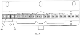
- each of the elongated slots 54 is a V-shape slot, a bottom of which is provided with a slit or a plurality of apertures 54a communicated with the chamber 52.
- the elongated slots may take other shapes such as a semicircular shape, as long as the apertures of the elongated slots near the bare fiber are larger enough to facilitate the oblique bare fiber to be adsorbed into the elongated slots.
- the slit or apertures 54a may extend through the entire elongated slots, and may also be only arranged along a part of a length of the elongated slots. A shape of the slit or apertures is selected based on desired adsorption force.
- the above description of the elongated slots may also be applicable to others of the present invention.
- the chamber 52 may be communicated with a vacuum source (not shown).
- the chamber 52 may be provided with a gas sucking unit sucking gas from the chamber (for example, see a gas sucking unit 57 in Fig.8 ). Vacuum degree or suction capability of the gas sucking unit may be adjusted to regulate the adsorption force of the elongated slots 54 on the bare fiber F1.
- the bare fiber F1 is in a straightening state suitable for the fiber inserting operation when being positioned in the elongated slots 54.
- the bare fiber F1 may be straightened by moving backwards and forwards through the elongated slots 54 in the fiber inserting direction.
- the adsorption force of the elongated slots 54 on the bare fiber F1 may be removed to prevent the bare fiber F1 from bending due to the adsorption force when the chamber 52 moves away from the bare fiber.
- the fiber inserting apparatus comprises: a chamber support 51; a supporting frame 53; a seat 55 disposed on the supporting frame 53; two screws driven synchronously, each of which passing through threaded holes in the chamber support 51 with both ends of each of the screws being supported by the seat 55, the chamber support 51 moving in axial directions of the screws parallel to the fiber inserting direction based on rotations of the screws; a hydraulic cylinder or an air cylinder 56a disposed on the chamber support, one end of a piston rod 56b of which being connected to the chamber 52, wherein the first drive includes the hydraulic cylinder or the air cylinder 56a and the piston rod 56b, and the second drive includes the two screws.
- a length of each of the elongated slots in the fiber inserting direction is In an exemplary embodiment of the present invention equal to or larger than that of the bare fiber exposed from the fiber clamp.
- the straightening section 50 without the second drive may not be fixed with respect to the fiber clamp.
- the straightening section 50 is preferably fixed relative to the fiber clamp 10.
- the chamber support 51 is provided with a plurality of fixing holes 51a, and a seat for fixing the fiber clamp may be provided with fasteners, such as bolts, engaging with the fixing holes 51.
- fasteners such as bolts
- the table 30 is provided with an opening between the fiber clamp 10 and the ferrule clamp 20 extending in the fiber inserting direction. At least one part of the supporting frame 53 is positioned in the opening.
- the supporting frame 53 is fixed in position with respect to the fiber clamp 10.
- the straightening section 50 can move with the fiber clamp before the bare fiber is inserted into the ferrule and performa straightening process on the bent bare fiber, and when performing the fiber operation, the chamber 52 can retract downwards to retract into the machine table control box for example, so that the normal fiber inserting operation is not affected.
- the fiber clamp 10 is adapted to move with respect to the ferrule clamp 20. In this way, the supporting frame 53 and thus the chamber 52 can move with the fiber clamp 10.
- the fiber clamp 10 may not be fixed in position relative to the supporting frame 53.
- the supporting frame 53 keeps stationary so that the straightening section 50 is always in the position shown in Fig.1 in the fiber inserting direction. In that case, when it is necessary to perform the straightening operation, the fiber clamp 10 is need to be returned to a position suitable for performing the straightening operation, i.e., the position in which the fiber clamp is located in Fig.1 .
- the chamber is provided with guide rods 59, and the chamber support is provided with guide holes in which the guide rods are positioned when the chamber moves based on an action of the piston rod. This ensures the chamber 52 can move for example in a vertical direction to maintain the extending direction of the elongated slots 54 to be parallel to the fiber inserting direction. As illustrated in Fig.9 , the elongated slots 54 extend in the fiber inserting direction.
- the bare fiber F1 may be observed to determine whether the bare fiber is in a straight state by means of the human visual.
- a bare fiber bend detecting section 60 may be provided to detect the straightness of the one end of the bare fiber which is exposed.
- a straightening control may be used to control the first and second drives based on signals from the bare fiber bend detecting section.
- the fiber clamp 10 may be adapted to simultaneously hold a plurality of fibers in parallel and the ferrule clamp 20 may be adapted to simultaneously hold a plurality of ferrules in parallel, as illustrated in Fig.1 .
- the fiber clamp 10 may hold 18 fibers at one time.
- one of the fiber clamp 10 and the ferrule clamp 20 (the fiber clamp 10 in Fig. 1 ) is provided with a guide bar 14, and the other of the fiber clamp 10 and the ferrule clamp 20 (the ferrule clamp 20 in Fig.1 ) is provided with a guide hole 24 into which the guide bar 14 is adapted to be inserted during the fiber inserting operation.
- the guide bar 14 can be inserted into the guide hole 24, if not, the guide bar 14 cannot be inserted into the guide hole 24.
- the fiber clamp and the ferrule clamp can be aligned with each other due to the guidance of the guide bar and the guide hole during the fiber inserting operation.
- the straightening section 50 includes a plurality of elongated slots 54 formed in parallel on the chamber 52, each of which corresponds to one bare fiber and one corresponding ferrule. In other words, if one bare fiber is straight, an extension line thereof will pass through an opening of its corresponding ferrule.
- the elongated slot into which the straightening operation is performed on the bare fiber is arranged so that the bare fiber is in the straight state and the extension line thereof passes through the opening of its corresponding ferrule when the bare fiber is adsorbed into the elongated slot.
- a bare fiber bend detecting section 60 In order to determine whether each bare fiber is in the straight state suitable for fiber insertion, it is necessary to provide a bare fiber bend detecting section 60 to detect a straightness of one end of each bare fiber which is exposed. An operation and a structure of the bare fiber bend detecting section 60 will be described in details below.
- the bare fiber bend detecting section 60 may detect whether spaces between adjacent bare fibers of a plurality of parallel bare fibers F1 are same as each other and/or the plurality of bare fibers are located in a same plane. If the bare fiber bend detecting section 60 detects the spaces between the adjacent bare fibers of the plurality of parallel bare fibers F1 are different from each other, it is indicated that the bare fibers deflect in a fore-and-aft direction in Fig.1 for example. If the bare fiber bend detecting section 60 detects the bare fibers are located in different planes, it is indicated that the bare fibers deflect in the up-and-down direction in Fig. 1 . The bare fiber bend detecting section 60 may detect one or both of these deflections.
- the bare fiber bend detecting section 60 comprises an optical camera 62 and a camera support 64, and determines whether the spaces between the adjacent bare fibers of the plurality of parallel bare fibers F1 are same as each other based on positions of the plurality of bare fibers F1 in field of view of the optical camera, and/or determines whether the plurality of bare fibers are in the same plane based on sharpness of the plurality of bare fibers in the field of view of the optical camera such as a CCD (Charge Coupled Device) camera.
- CCD Charge Coupled Device
- the optical camera 62 may be adapted to move relative to the camera support 64 parallel to the plane defined by the plurality of bare fibers in the straight state and perpendicular to the fiber inserting direction, particularly, in the fore-and-aft direction in Fig.1 , to scan all of the bare fibers on the fiber clamp 10.
- the camera support 64 is provided with rails 64a along which a camera seat 62a of the camera 62 is movable. Movement of the camera seat 62a can be achieved by a motor 66.
- the camera support 64 comprises a supporting seat 64b for fixing the camera support to the table.
- the optical camera 62 and the straightening section 50 are disposed on upper and lower sides of the bare fibers of the fibers arranged in parallel with each other, respectively. In this way, the straightening operation can be performed on the bare fibers therebelow, and determining whether the bare fibers are in the straight state may be performed thereabove. This arrangement will facilitate effectively utilizing the space.
- the fiber inserting apparatus comprises a console including the clamp control 40.
- the console is located on one side of the fiber clamp 10 in the fiber inserting direction (the front side in Fig.1 ) and the camera support 64 is located on the other side of the fiber clamp 10 in the fiber inserting direction (the rear side in Fig. 1 ).
- the bare fiber bend detecting section 60 may also include two parts, i.e., a space detector detecting whether the spaces between the adjacent bare fibers perpendicular to the fiber inserting direction in the plane defined by the plurality of bare fibers in the straight state are same as each other; and a deflection detector detecting whether a deflection or an amount of the deflection of one end of each bare fiber from the plane defined by the plurality of bare fibers in the straight state exceeds a predetermined threshold.
- the space detector may directly measure the space between each pair of adjacent bare fibers parallel to the plane defined by the plurality of bare fibers in the straight state and then determine whether a change in the space is in a tolerable range.
- the deflection detector may be a pair of light emitter and light receiver disposed on the upper and lower sides of the bare fibers arranged parallel with each other respectively.
- the light emitter is disposed on the front side in Fig. 1
- the light receiver is disposed on the rear side in Fig. 1 .
- Light emitted by the light emitter will reach the light receiver if not being blocked, which indicates that the deflection of the bare fibers out of the plane does not occur on this side, otherwise the deflection of the bare fibers exceeds the predetermined threshold and thus it is necessary to perform the straightening operation.
- a dedicated straightening section may be provided to control the first and second drives based on signals from the bare fiber bend detecting section.
- the straightening section for example is disposed on the clamp control 40 for example.
- the bare fiber bend detecting section 60 and the straightening section 50 perform the straightness detection and process on the fibers (the bare fibers) to be inserted into the ferrules to ensure quality and effectiveness of the fiber insertion.
- the console may comprise the clamp control and the straightening control.
- the fiber inserting apparatus further comprises a ferrule clamp seat 36 disposed on the table 30 onto which one ferrule clamp 20 is adapted to be releasably fixed.
- the fiber inserting apparatus further comprises a ferrule clamp holder 70 for holding the ferrule clamp 20 to be inserted with the fibers onto and/or removing the ferrule clamp 20 inserted with the fibers from the ferrule clamp seat 36.
- the ferrule clamp has a double-layer ferrule structure including upper and lower ferrule layers22 arranged in parallel with each other.
- an engaging notch 26 is provided on each side in a direction in which the ferrules in the ferrule clamp 20 are arranged in parallel with each other, respectively.
- the ferrule clamp holder 70 includes two engaged arms 72 which are movable relative to each other with one end of each engaging arm being adapted to be engaged into the engaging notch 26.
- the ferrule clamp holder 70 further includes a lifting mechanism 74 and a turning mechanism 76 connected to the lifting mechanism 74.
- the turning mechanism 76 turns the two engaged arms 72 to turn the ferrule clamp 20 held by the engaging arms by 180 degrees, and the lifting mechanism 74 moves the turned ferrule clamp onto the ferrule clamp seat 36.
- the turning mechanism described above may comprise a turning plate 76a and a rotating member 76b for driving the turning plate.
- Movable guide grooves or movable rails 76a1 are disposed on one side of the turning plate 76a facing to the ferrule clamp 20 (the left side in Fig.6 ).
- the other end of each engaged arm 72 is provided with a guide block 75 cooperating with the movable guide grooves or movable rails 76a1.
- a through-hole 76a2 is formed in a middle position of the turning plate76a between two guide blocks 75.
- a driving rod 77 passes through the through-hole 76a2, and a first joint 78 is disposed at one end of the driving rod 77 passing through the through-hole and near the ferrule clamp (the left end in Fig.6 ).
- One end of each of two connecting levels 79 is pivotably connected to the first joint 78, respectively, and the other end of each connecting levels 79 is pivotably connected to the guide block 75, respectively.
- each engaged arm 72 is engaged into the engaging notch 26 to hold the ferrule clamp 20 based on a movement of the one end of the driving rod 77 away from the turning plate 76a, and the one end of each engaged arm 72 is disengaged from the engaging notch 26 based on a movement of the one end of the driving rod towards the turning plate 76a.
- the ferrule clamp 20 can be turned to perform the fiber inserting operation on the other side through the turning mechanism without removing the ferrule clamp.
- the lifting mechanism 74 comprises lifting rails 74a and a carrying mechanism 74b for the turning mechanism adapted to be lifted along the lifting rails 74a.
- a mechanism providing a driving force is disposed in the carrying mechanism.
- the console described above is located on one side of the ferrule clamp 20 in the fiber inserting direction (the front side in Fig. 1 ), and the lifting mechanism 74 is located on the other side of the ferrule clamp 20 in the fiber inserting direction (the rear side in Fig.1 ).
- the present invention provides a semiautomatic fiber inserting machine which can insert 18 fibers at one time compared to the conventional fiber inserting machine which can only insert one fiber at one time.
- the turning clamp of ceramic ferrules can perform the fiber insertion on the other side without removing the ceramic ferrules.
- the straightening section can ensure the fibers are straight before being inserted into the ceramic ferrules, and the fiber bend detecting section can further ensure the straightness of the fibers. Therefore, the fibers can be efficiently and accurately inserted.
- the present invention overcomes the defect of un-straight fibers, low fiber inserting efficiency and the like occurred in the conventional fiber inserting machine.
- the fiber inserting method comprises: providing a fiber clamp 10 and a ferrule clamp 20 opposite to the fiber clamp 10; controlling relative movement of the fiber clamp 10 and the ferrule clamp 20 towards each other to perform a fiber inserting operation by a control such as the clamp control 40 as described above.
- a control such as the clamp control 40 as described above.
- the method described above may further comprise detecting whether an end of the bare fiber to be inserted on the fiber clamp is in a straight state. Particularly, it is possible to detect or determine whether the end of the bare fiber to be inserted on the fiber clamp is in the straight state after the fiber clamp and the ferrule clamp move towards each other by a predetermined distance.
- the method described above further comprises performing a straightening process on the end of the bare fiber to be inserted on the fiber clamp if the end of the bare fiber is detected not to be in the straight state.
- the straightening process may be performed when the fiber clamp 10 is in a predetermined position in a fiber inserting direction, for example, when the fiber clamp 10 is in the position as illustrated in Fig.1 .
- the method described above may be applicable to a case where a plurality of bare fibers are synchronously inserted into a plurality of ferrules.
- performing a straightening process may comprise: providing a chamber 52 provided with elongated slots 54 extending in the fiber inserting direction, the elongated slots 54 are in communication with the chamber and an outside air is drawn into the chamber; driving the chamber 52 towards ends of the bare fibers to be inserted, so that the ends of the bare fibers to be inserted is adsorbed into the corresponding elongated slots 54 to be in the straight state suitable for the fiber inserting operation; moving the chamber 52 backwards and forwards in the fiber inserting direction; stopping drawing the outside air into the chamber 52; and moving the chamber 52 away from the ends of the bare fibers to be inserted.
- an interior of the chamber 52 is communicated with a vacuum source or air is drawn from the chamber to form adsorption forces at the elongated slots during providing the chamber provided with the elongated slots.
- detecting whether ends of the bare fibers to be inserted on the fiber clamp are in the straight state may comprise determining whether spaces between adjacent bare fibers of the plurality of parallel bare fibers are same as each other and/or the plurality of bare fibers are located in a same plane. Particularly, it is possible to determine whether the spaces between the adjacent bare fibers of the plurality of bare fibers are same as each other based on positions of the plurality of bare fibers in a field of view of an optical camera, and/or determine whether the plurality of bare fibers are in the same place based on definitions of the plurality of bare fibers in the field of view of the optical camera.
- a space detector detects whether spaces between the adjacent bare fibers perpendicular to the fiber inserting direction in a plane defined by the plurality of bare fibers in the straight state are same as each other by a space detector and detect whether a deflection or an amount of the deflection of one end of each bare fiber from the plane defined by the plurality of bare fibers in the straight state exceeds a predetermined threshold by a deflection detector.
- the ferrule clamp 20 may have a double-layer ferrule structure including an upper ferrule layer and a lower ferrule layer arranged in parallel with each other. After completing the fiber inserting operation on one of the upper ferrule layer and the lower ferrule layer, the method further comprises arranging fibers on the fiber clamp, or replacing the fiber clamp arranged with fibers; and turning the fiber clamp by 180 degrees to be ready for performing the fiber inserting operation on the other of the upper ferrule layer and the lower ferrule layer.
- the present invention it is possible to simply operate the fiber insertion of 18 ferrules at a time, saving labor time and improving efficiency of the fiber insertion.
- the bare fiber bend detecting section and the straightening section may also ensure the quality and efficiency of the fiber insertion.
Landscapes
- Physics & Mathematics (AREA)
- General Physics & Mathematics (AREA)
- Optics & Photonics (AREA)
- Mechanical Coupling Of Light Guides (AREA)
Priority Applications (1)
| Application Number | Priority Date | Filing Date | Title |
|---|---|---|---|
| PL14759345T PL3047322T3 (pl) | 2013-09-18 | 2014-09-01 | Automatyczne urządzenie wprowadzające światłowód i sposób wprowadzania światłowodu |
Applications Claiming Priority (3)
| Application Number | Priority Date | Filing Date | Title |
|---|---|---|---|
| CN201310428328.9A CN104440049B (zh) | 2013-09-18 | 2013-09-18 | 穿纤装置和穿纤方法 |
| CN201320581145.6U CN203526926U (zh) | 2013-09-18 | 2013-09-18 | 穿纤装置 |
| PCT/IB2014/064170 WO2015040516A1 (en) | 2013-09-18 | 2014-09-01 | Automatic optical fiber inserting apparatus and fiber inserting method |
Publications (2)
| Publication Number | Publication Date |
|---|---|
| EP3047322A1 EP3047322A1 (en) | 2016-07-27 |
| EP3047322B1 true EP3047322B1 (en) | 2018-07-11 |
Family
ID=65360422
Family Applications (1)
| Application Number | Title | Priority Date | Filing Date |
|---|---|---|---|
| EP14759345.3A Not-in-force EP3047322B1 (en) | 2013-09-18 | 2014-09-01 | Automatic optical fiber inserting apparatus and fiber inserting method |
Country Status (4)
| Country | Link |
|---|---|
| US (2) | US10120139B2 (pl) |
| EP (1) | EP3047322B1 (pl) |
| PL (1) | PL3047322T3 (pl) |
| WO (1) | WO2015040516A1 (pl) |
Cited By (1)
| Publication number | Priority date | Publication date | Assignee | Title |
|---|---|---|---|---|
| CN109470629A (zh) * | 2018-10-09 | 2019-03-15 | 宁波大红鹰学院 | 陶瓷插芯强度检测机 |
Families Citing this family (3)
| Publication number | Priority date | Publication date | Assignee | Title |
|---|---|---|---|---|
| CN108908214A (zh) * | 2018-06-04 | 2018-11-30 | 宜昌红旗中泰电缆有限公司 | 高精度穿光纤机构及操作方法 |
| CN109613649B (zh) * | 2019-01-22 | 2020-07-14 | 东莞市翔通光电技术有限公司 | 一种自动穿光纤机 |
| CN112415682B (zh) * | 2020-10-30 | 2023-04-07 | 桂林东衡光通讯技术有限公司 | 一种用于aoc跳线推尾套的专用工具 |
Family Cites Families (15)
| Publication number | Priority date | Publication date | Assignee | Title |
|---|---|---|---|---|
| US3591294A (en) * | 1969-01-31 | 1971-07-06 | Univ Tennessee Res Corp | Fiber measurement |
| US4464817A (en) | 1982-05-24 | 1984-08-14 | Amp Incorporated | Optical waveguide terminating apparatus |
| JP2683527B2 (ja) * | 1987-03-05 | 1997-12-03 | アンプ インコーポレーテッド | 光ファイバケーブル端部処理装置 |
| JPH0776803B2 (ja) | 1987-03-20 | 1995-08-16 | 日本電信電話株式会社 | フエル−ルへの光フアイバ挿入方法 |
| US4994079A (en) | 1989-07-28 | 1991-02-19 | C. R. Bard, Inc. | Grasping forceps |
| JP2717897B2 (ja) | 1991-12-05 | 1998-02-25 | 株式会社フジクラ | フェルールに光ファイバを挿入する装置 |
| JP2704338B2 (ja) | 1992-01-10 | 1998-01-26 | 株式会社フジクラ | コネクタフェルールに光ファイバを挿入する装置 |
| JPH07218766A (ja) | 1994-01-31 | 1995-08-18 | Furukawa Electric Co Ltd:The | 光ファイバの自動挿入方法およびその装置 |
| JP2001166179A (ja) * | 1999-12-03 | 2001-06-22 | Sumitomo Electric Ind Ltd | 光コネクタの組立方法及び光コネクタの組立工具 |
| JP2003029089A (ja) | 2001-05-10 | 2003-01-29 | Furukawa Electric Co Ltd:The | 光ファイバ挿入工具 |
| US20030000257A1 (en) * | 2001-06-29 | 2003-01-02 | Chang Chester Hann Huei | Single step fiber preparation |
| JP2003121693A (ja) | 2001-10-17 | 2003-04-23 | Tamura Electric Works Ltd | 光ファイバ挿入装置およびその挿入方法 |
| US6628886B2 (en) * | 2002-01-04 | 2003-09-30 | Iphotonics, Inc. | Integrated processing system for optical devices |
| CN203526926U (zh) | 2013-09-18 | 2014-04-09 | 泰科电子(上海)有限公司 | 穿纤装置 |
| US20160124156A1 (en) * | 2014-10-29 | 2016-05-05 | Compass Electro Optical Systems Ltd. | Method for establishing a multi-fiber optical cross-connection |
-
2014
- 2014-09-01 WO PCT/IB2014/064170 patent/WO2015040516A1/en not_active Ceased
- 2014-09-01 EP EP14759345.3A patent/EP3047322B1/en not_active Not-in-force
- 2014-09-01 US US15/023,324 patent/US10120139B2/en not_active Expired - Fee Related
- 2014-09-01 PL PL14759345T patent/PL3047322T3/pl unknown
-
2018
- 2018-08-21 US US16/107,334 patent/US10379296B2/en not_active Expired - Fee Related
Non-Patent Citations (1)
| Title |
|---|
| None * |
Cited By (1)
| Publication number | Priority date | Publication date | Assignee | Title |
|---|---|---|---|---|
| CN109470629A (zh) * | 2018-10-09 | 2019-03-15 | 宁波大红鹰学院 | 陶瓷插芯强度检测机 |
Also Published As
| Publication number | Publication date |
|---|---|
| WO2015040516A1 (en) | 2015-03-26 |
| US20160223758A1 (en) | 2016-08-04 |
| US20190056556A1 (en) | 2019-02-21 |
| EP3047322A1 (en) | 2016-07-27 |
| US10379296B2 (en) | 2019-08-13 |
| PL3047322T3 (pl) | 2018-12-31 |
| US10120139B2 (en) | 2018-11-06 |
Similar Documents
| Publication | Publication Date | Title |
|---|---|---|
| EP3047322B1 (en) | Automatic optical fiber inserting apparatus and fiber inserting method | |
| US10036858B2 (en) | System and method of automatically inserting fiber | |
| JP2016517152A (ja) | ケーブルを切断し、ケーブルから絶縁体を剥離し、ケーブルを圧着端子に取り付けるためのケーブル処理装置 | |
| US20160322792A1 (en) | Cable processing equipment and method for removing a screening film from a screened multi-core round cable | |
| EP3697569B1 (en) | Conductor positioning fixture for cable processing | |
| JP7187142B2 (ja) | ケーブル処理装置 | |
| US11495933B2 (en) | Assembly system | |
| KR102288084B1 (ko) | 미세 동축 케이블의 탈피가 용이한 자동 탈피기 및 이를 통한 자동 탈피방법 | |
| JP6513886B2 (ja) | 自動ファイバストリップシステムおよび方法 | |
| US20190372291A1 (en) | Terminal insertion device and terminal insertion method | |
| CN104838548A (zh) | 电线分类固定装置和电线分类的方法 | |
| CN113872017B (zh) | 一种网线线芯自动排序整理装置 | |
| US4051749A (en) | Cable insulation stripping apparatus | |
| CN103777289B (zh) | 多光缆植纤方法、多光缆植纤设备和光缆承载台 | |
| CN114883148A (zh) | 一种继电器接触系统部件的自动焊接机 | |
| CN110764189A (zh) | 一种自动光纤剥皮机 | |
| EP1408357B1 (en) | Optical fiber axial alignment method and related device, and optical fiber fusion splicing method | |
| CN102954738A (zh) | 烟花引线自动安插装置 | |
| CN202837587U (zh) | 光缆热剥机 | |
| US4949451A (en) | Device for plugging contacts into a connector box | |
| JP4420617B2 (ja) | 溶接装置 | |
| US20100170089A1 (en) | Automated wiring apparatus and method | |
| CN119171704B (zh) | 高精度刮漆装置及其刮漆方法 | |
| CN217159131U (zh) | 剪线机 | |
| JPH1014045A (ja) | ケーブル被覆体のストリップ装置 |
Legal Events
| Date | Code | Title | Description |
|---|---|---|---|
| PUAI | Public reference made under article 153(3) epc to a published international application that has entered the european phase |
Free format text: ORIGINAL CODE: 0009012 |
|
| 17P | Request for examination filed |
Effective date: 20160415 |
|
| AK | Designated contracting states |
Kind code of ref document: A1 Designated state(s): AL AT BE BG CH CY CZ DE DK EE ES FI FR GB GR HR HU IE IS IT LI LT LU LV MC MK MT NL NO PL PT RO RS SE SI SK SM TR |
|
| AX | Request for extension of the european patent |
Extension state: BA ME |
|
| RIN1 | Information on inventor provided before grant (corrected) |
Inventor name: YUAN, YONGJUN Inventor name: LEE, HANG Inventor name: LENG, ZONGSHEN Inventor name: CHEN, CHUANWU |
|
| DAX | Request for extension of the european patent (deleted) | ||
| RIN1 | Information on inventor provided before grant (corrected) |
Inventor name: YUAN, YONGJUN Inventor name: LEE, HANG Inventor name: CHEN, CHUANWU Inventor name: LENG, ZONGSHEN |
|
| STAA | Information on the status of an ep patent application or granted ep patent |
Free format text: STATUS: REQUEST FOR EXAMINATION WAS MADE |
|
| RAP1 | Party data changed (applicant data changed or rights of an application transferred) |
Owner name: ADC TELECOMMUNICATIONS (SHANGHAI) DISTRIBUTION CO. |
|
| GRAP | Despatch of communication of intention to grant a patent |
Free format text: ORIGINAL CODE: EPIDOSNIGR1 |
|
| STAA | Information on the status of an ep patent application or granted ep patent |
Free format text: STATUS: GRANT OF PATENT IS INTENDED |
|
| INTG | Intention to grant announced |
Effective date: 20180123 |
|
| GRAJ | Information related to disapproval of communication of intention to grant by the applicant or resumption of examination proceedings by the epo deleted |
Free format text: ORIGINAL CODE: EPIDOSDIGR1 |
|
| STAA | Information on the status of an ep patent application or granted ep patent |
Free format text: STATUS: REQUEST FOR EXAMINATION WAS MADE |
|
| GRAR | Information related to intention to grant a patent recorded |
Free format text: ORIGINAL CODE: EPIDOSNIGR71 |
|
| GRAS | Grant fee paid |
Free format text: ORIGINAL CODE: EPIDOSNIGR3 |
|
| STAA | Information on the status of an ep patent application or granted ep patent |
Free format text: STATUS: GRANT OF PATENT IS INTENDED |
|
| GRAA | (expected) grant |
Free format text: ORIGINAL CODE: 0009210 |
|
| STAA | Information on the status of an ep patent application or granted ep patent |
Free format text: STATUS: THE PATENT HAS BEEN GRANTED |
|
| INTC | Intention to grant announced (deleted) | ||
| AK | Designated contracting states |
Kind code of ref document: B1 Designated state(s): AL AT BE BG CH CY CZ DE DK EE ES FI FR GB GR HR HU IE IS IT LI LT LU LV MC MK MT NL NO PL PT RO RS SE SI SK SM TR |
|
| INTG | Intention to grant announced |
Effective date: 20180605 |
|
| REG | Reference to a national code |
Ref country code: GB Ref legal event code: FG4D |
|
| REG | Reference to a national code |
Ref country code: CH Ref legal event code: EP |
|
| REG | Reference to a national code |
Ref country code: AT Ref legal event code: REF Ref document number: 1017502 Country of ref document: AT Kind code of ref document: T Effective date: 20180715 |
|
| REG | Reference to a national code |
Ref country code: IE Ref legal event code: FG4D |
|
| REG | Reference to a national code |
Ref country code: DE Ref legal event code: R096 Ref document number: 602014028336 Country of ref document: DE |
|
| REG | Reference to a national code |
Ref country code: RO Ref legal event code: EPE |
|
| REG | Reference to a national code |
Ref country code: NL Ref legal event code: MP Effective date: 20180711 |
|
| REG | Reference to a national code |
Ref country code: LT Ref legal event code: MG4D |
|
| REG | Reference to a national code |
Ref country code: AT Ref legal event code: MK05 Ref document number: 1017502 Country of ref document: AT Kind code of ref document: T Effective date: 20180711 |
|
| PG25 | Lapsed in a contracting state [announced via postgrant information from national office to epo] |
Ref country code: NL Free format text: LAPSE BECAUSE OF FAILURE TO SUBMIT A TRANSLATION OF THE DESCRIPTION OR TO PAY THE FEE WITHIN THE PRESCRIBED TIME-LIMIT Effective date: 20180711 |
|
| PG25 | Lapsed in a contracting state [announced via postgrant information from national office to epo] |
Ref country code: IS Free format text: LAPSE BECAUSE OF FAILURE TO SUBMIT A TRANSLATION OF THE DESCRIPTION OR TO PAY THE FEE WITHIN THE PRESCRIBED TIME-LIMIT Effective date: 20181111 Ref country code: RS Free format text: LAPSE BECAUSE OF FAILURE TO SUBMIT A TRANSLATION OF THE DESCRIPTION OR TO PAY THE FEE WITHIN THE PRESCRIBED TIME-LIMIT Effective date: 20180711 Ref country code: SE Free format text: LAPSE BECAUSE OF FAILURE TO SUBMIT A TRANSLATION OF THE DESCRIPTION OR TO PAY THE FEE WITHIN THE PRESCRIBED TIME-LIMIT Effective date: 20180711 Ref country code: AT Free format text: LAPSE BECAUSE OF FAILURE TO SUBMIT A TRANSLATION OF THE DESCRIPTION OR TO PAY THE FEE WITHIN THE PRESCRIBED TIME-LIMIT Effective date: 20180711 Ref country code: FI Free format text: LAPSE BECAUSE OF FAILURE TO SUBMIT A TRANSLATION OF THE DESCRIPTION OR TO PAY THE FEE WITHIN THE PRESCRIBED TIME-LIMIT Effective date: 20180711 Ref country code: GR Free format text: LAPSE BECAUSE OF FAILURE TO SUBMIT A TRANSLATION OF THE DESCRIPTION OR TO PAY THE FEE WITHIN THE PRESCRIBED TIME-LIMIT Effective date: 20181012 Ref country code: NO Free format text: LAPSE BECAUSE OF FAILURE TO SUBMIT A TRANSLATION OF THE DESCRIPTION OR TO PAY THE FEE WITHIN THE PRESCRIBED TIME-LIMIT Effective date: 20181011 Ref country code: BG Free format text: LAPSE BECAUSE OF FAILURE TO SUBMIT A TRANSLATION OF THE DESCRIPTION OR TO PAY THE FEE WITHIN THE PRESCRIBED TIME-LIMIT Effective date: 20181011 Ref country code: LT Free format text: LAPSE BECAUSE OF FAILURE TO SUBMIT A TRANSLATION OF THE DESCRIPTION OR TO PAY THE FEE WITHIN THE PRESCRIBED TIME-LIMIT Effective date: 20180711 |
|
| PG25 | Lapsed in a contracting state [announced via postgrant information from national office to epo] |
Ref country code: HR Free format text: LAPSE BECAUSE OF FAILURE TO SUBMIT A TRANSLATION OF THE DESCRIPTION OR TO PAY THE FEE WITHIN THE PRESCRIBED TIME-LIMIT Effective date: 20180711 Ref country code: AL Free format text: LAPSE BECAUSE OF FAILURE TO SUBMIT A TRANSLATION OF THE DESCRIPTION OR TO PAY THE FEE WITHIN THE PRESCRIBED TIME-LIMIT Effective date: 20180711 Ref country code: LV Free format text: LAPSE BECAUSE OF FAILURE TO SUBMIT A TRANSLATION OF THE DESCRIPTION OR TO PAY THE FEE WITHIN THE PRESCRIBED TIME-LIMIT Effective date: 20180711 |
|
| REG | Reference to a national code |
Ref country code: DE Ref legal event code: R119 Ref document number: 602014028336 Country of ref document: DE |
|
| PG25 | Lapsed in a contracting state [announced via postgrant information from national office to epo] |
Ref country code: IT Free format text: LAPSE BECAUSE OF FAILURE TO SUBMIT A TRANSLATION OF THE DESCRIPTION OR TO PAY THE FEE WITHIN THE PRESCRIBED TIME-LIMIT Effective date: 20180711 Ref country code: ES Free format text: LAPSE BECAUSE OF FAILURE TO SUBMIT A TRANSLATION OF THE DESCRIPTION OR TO PAY THE FEE WITHIN THE PRESCRIBED TIME-LIMIT Effective date: 20180711 Ref country code: MC Free format text: LAPSE BECAUSE OF FAILURE TO SUBMIT A TRANSLATION OF THE DESCRIPTION OR TO PAY THE FEE WITHIN THE PRESCRIBED TIME-LIMIT Effective date: 20180711 Ref country code: EE Free format text: LAPSE BECAUSE OF FAILURE TO SUBMIT A TRANSLATION OF THE DESCRIPTION OR TO PAY THE FEE WITHIN THE PRESCRIBED TIME-LIMIT Effective date: 20180711 |
|
| REG | Reference to a national code |
Ref country code: CH Ref legal event code: PL |
|
| PLBE | No opposition filed within time limit |
Free format text: ORIGINAL CODE: 0009261 |
|
| STAA | Information on the status of an ep patent application or granted ep patent |
Free format text: STATUS: NO OPPOSITION FILED WITHIN TIME LIMIT |
|
| PG25 | Lapsed in a contracting state [announced via postgrant information from national office to epo] |
Ref country code: DK Free format text: LAPSE BECAUSE OF FAILURE TO SUBMIT A TRANSLATION OF THE DESCRIPTION OR TO PAY THE FEE WITHIN THE PRESCRIBED TIME-LIMIT Effective date: 20180711 Ref country code: SM Free format text: LAPSE BECAUSE OF FAILURE TO SUBMIT A TRANSLATION OF THE DESCRIPTION OR TO PAY THE FEE WITHIN THE PRESCRIBED TIME-LIMIT Effective date: 20180711 Ref country code: SK Free format text: LAPSE BECAUSE OF FAILURE TO SUBMIT A TRANSLATION OF THE DESCRIPTION OR TO PAY THE FEE WITHIN THE PRESCRIBED TIME-LIMIT Effective date: 20180711 |
|
| REG | Reference to a national code |
Ref country code: BE Ref legal event code: MM Effective date: 20180930 |
|
| 26N | No opposition filed |
Effective date: 20190412 |
|
| PG25 | Lapsed in a contracting state [announced via postgrant information from national office to epo] |
Ref country code: LU Free format text: LAPSE BECAUSE OF NON-PAYMENT OF DUE FEES Effective date: 20180901 |
|
| PG25 | Lapsed in a contracting state [announced via postgrant information from national office to epo] |
Ref country code: DE Free format text: LAPSE BECAUSE OF NON-PAYMENT OF DUE FEES Effective date: 20190402 |
|
| PG25 | Lapsed in a contracting state [announced via postgrant information from national office to epo] |
Ref country code: LI Free format text: LAPSE BECAUSE OF NON-PAYMENT OF DUE FEES Effective date: 20180930 Ref country code: CH Free format text: LAPSE BECAUSE OF NON-PAYMENT OF DUE FEES Effective date: 20180930 Ref country code: SI Free format text: LAPSE BECAUSE OF FAILURE TO SUBMIT A TRANSLATION OF THE DESCRIPTION OR TO PAY THE FEE WITHIN THE PRESCRIBED TIME-LIMIT Effective date: 20180711 Ref country code: FR Free format text: LAPSE BECAUSE OF NON-PAYMENT OF DUE FEES Effective date: 20180911 Ref country code: BE Free format text: LAPSE BECAUSE OF NON-PAYMENT OF DUE FEES Effective date: 20180930 |
|
| PGFP | Annual fee paid to national office [announced via postgrant information from national office to epo] |
Ref country code: IE Payment date: 20190927 Year of fee payment: 6 |
|
| PGFP | Annual fee paid to national office [announced via postgrant information from national office to epo] |
Ref country code: GB Payment date: 20190927 Year of fee payment: 6 |
|
| PG25 | Lapsed in a contracting state [announced via postgrant information from national office to epo] |
Ref country code: MT Free format text: LAPSE BECAUSE OF NON-PAYMENT OF DUE FEES Effective date: 20180901 |
|
| PG25 | Lapsed in a contracting state [announced via postgrant information from national office to epo] |
Ref country code: TR Free format text: LAPSE BECAUSE OF FAILURE TO SUBMIT A TRANSLATION OF THE DESCRIPTION OR TO PAY THE FEE WITHIN THE PRESCRIBED TIME-LIMIT Effective date: 20180711 |
|
| PG25 | Lapsed in a contracting state [announced via postgrant information from national office to epo] |
Ref country code: PT Free format text: LAPSE BECAUSE OF FAILURE TO SUBMIT A TRANSLATION OF THE DESCRIPTION OR TO PAY THE FEE WITHIN THE PRESCRIBED TIME-LIMIT Effective date: 20180711 |
|
| PG25 | Lapsed in a contracting state [announced via postgrant information from national office to epo] |
Ref country code: MK Free format text: LAPSE BECAUSE OF NON-PAYMENT OF DUE FEES Effective date: 20180711 Ref country code: CY Free format text: LAPSE BECAUSE OF FAILURE TO SUBMIT A TRANSLATION OF THE DESCRIPTION OR TO PAY THE FEE WITHIN THE PRESCRIBED TIME-LIMIT Effective date: 20180711 Ref country code: HU Free format text: LAPSE BECAUSE OF FAILURE TO SUBMIT A TRANSLATION OF THE DESCRIPTION OR TO PAY THE FEE WITHIN THE PRESCRIBED TIME-LIMIT; INVALID AB INITIO Effective date: 20140901 |
|
| PGFP | Annual fee paid to national office [announced via postgrant information from national office to epo] |
Ref country code: RO Payment date: 20200825 Year of fee payment: 7 Ref country code: CZ Payment date: 20200819 Year of fee payment: 7 |
|
| PGFP | Annual fee paid to national office [announced via postgrant information from national office to epo] |
Ref country code: PL Payment date: 20200820 Year of fee payment: 7 |
|
| GBPC | Gb: european patent ceased through non-payment of renewal fee |
Effective date: 20200901 |
|
| PG25 | Lapsed in a contracting state [announced via postgrant information from national office to epo] |
Ref country code: GB Free format text: LAPSE BECAUSE OF NON-PAYMENT OF DUE FEES Effective date: 20200901 Ref country code: IE Free format text: LAPSE BECAUSE OF NON-PAYMENT OF DUE FEES Effective date: 20200901 |
|
| PG25 | Lapsed in a contracting state [announced via postgrant information from national office to epo] |
Ref country code: RO Free format text: LAPSE BECAUSE OF NON-PAYMENT OF DUE FEES Effective date: 20210901 Ref country code: CZ Free format text: LAPSE BECAUSE OF NON-PAYMENT OF DUE FEES Effective date: 20210901 |
|
| PG25 | Lapsed in a contracting state [announced via postgrant information from national office to epo] |
Ref country code: PL Free format text: LAPSE BECAUSE OF NON-PAYMENT OF DUE FEES Effective date: 20210901 |