EP3046833B1 - Holding device for holding a ship's boat or other additional component to be carried along, and use of said device - Google Patents
Holding device for holding a ship's boat or other additional component to be carried along, and use of said device Download PDFInfo
- Publication number
- EP3046833B1 EP3046833B1 EP14793441.8A EP14793441A EP3046833B1 EP 3046833 B1 EP3046833 B1 EP 3046833B1 EP 14793441 A EP14793441 A EP 14793441A EP 3046833 B1 EP3046833 B1 EP 3046833B1
- Authority
- EP
- European Patent Office
- Prior art keywords
- ship
- holding device
- dinghy
- coupling
- hook
- Prior art date
- Legal status (The legal status is an assumption and is not a legal conclusion. Google has not performed a legal analysis and makes no representation as to the accuracy of the status listed.)
- Active
Links
- 230000008878 coupling Effects 0.000 claims description 71
- 238000010168 coupling process Methods 0.000 claims description 71
- 238000005859 coupling reaction Methods 0.000 claims description 71
- 239000004033 plastic Substances 0.000 claims description 8
- 229920003023 plastic Polymers 0.000 claims description 8
- 229910000831 Steel Inorganic materials 0.000 claims description 5
- 229910052782 aluminium Inorganic materials 0.000 claims description 5
- XAGFODPZIPBFFR-UHFFFAOYSA-N aluminium Chemical compound [Al] XAGFODPZIPBFFR-UHFFFAOYSA-N 0.000 claims description 5
- 239000010935 stainless steel Substances 0.000 claims description 5
- 229910001220 stainless steel Inorganic materials 0.000 claims description 5
- 239000010959 steel Substances 0.000 claims description 5
- 239000000463 material Substances 0.000 claims description 4
- 238000003287 bathing Methods 0.000 claims description 3
- 239000000969 carrier Substances 0.000 claims description 3
- 239000002131 composite material Substances 0.000 claims description 3
- 239000004411 aluminium Substances 0.000 claims 2
- 239000000835 fiber Substances 0.000 claims 2
- OKTJSMMVPCPJKN-UHFFFAOYSA-N Carbon Chemical compound [C] OKTJSMMVPCPJKN-UHFFFAOYSA-N 0.000 claims 1
- 235000021168 barbecue Nutrition 0.000 claims 1
- 229910052799 carbon Inorganic materials 0.000 claims 1
- 230000002401 inhibitory effect Effects 0.000 claims 1
- 230000000717 retained effect Effects 0.000 claims 1
- 230000000903 blocking effect Effects 0.000 description 26
- 230000006378 damage Effects 0.000 description 7
- 208000027418 Wounds and injury Diseases 0.000 description 4
- 238000010276 construction Methods 0.000 description 4
- 208000014674 injury Diseases 0.000 description 4
- VNWKTOKETHGBQD-UHFFFAOYSA-N methane Chemical compound C VNWKTOKETHGBQD-UHFFFAOYSA-N 0.000 description 4
- XLYOFNOQVPJJNP-UHFFFAOYSA-N water Substances O XLYOFNOQVPJJNP-UHFFFAOYSA-N 0.000 description 4
- 239000002023 wood Substances 0.000 description 4
- 238000006073 displacement reaction Methods 0.000 description 3
- 229910052751 metal Inorganic materials 0.000 description 3
- 238000000034 method Methods 0.000 description 3
- 239000013535 sea water Substances 0.000 description 3
- 229920000049 Carbon (fiber) Polymers 0.000 description 2
- 241000630329 Scomberesox saurus saurus Species 0.000 description 2
- 230000008901 benefit Effects 0.000 description 2
- 239000004917 carbon fiber Substances 0.000 description 2
- 230000007613 environmental effect Effects 0.000 description 2
- 239000002184 metal Substances 0.000 description 2
- 230000008569 process Effects 0.000 description 2
- 230000003014 reinforcing effect Effects 0.000 description 2
- 238000007796 conventional method Methods 0.000 description 1
- 230000005484 gravity Effects 0.000 description 1
- 230000003993 interaction Effects 0.000 description 1
- 230000013011 mating Effects 0.000 description 1
- 230000007246 mechanism Effects 0.000 description 1
- 239000007769 metal material Substances 0.000 description 1
- 230000001681 protective effect Effects 0.000 description 1
- 238000009420 retrofitting Methods 0.000 description 1
- 150000003839 salts Chemical class 0.000 description 1
- 230000035939 shock Effects 0.000 description 1
- 230000000007 visual effect Effects 0.000 description 1
Images


Classifications
-
- B—PERFORMING OPERATIONS; TRANSPORTING
- B63—SHIPS OR OTHER WATERBORNE VESSELS; RELATED EQUIPMENT
- B63B—SHIPS OR OTHER WATERBORNE VESSELS; EQUIPMENT FOR SHIPPING
- B63B23/00—Equipment for handling lifeboats or the like
- B63B23/62—Fastening or storing of boats on deck
-
- B—PERFORMING OPERATIONS; TRANSPORTING
- B63—SHIPS OR OTHER WATERBORNE VESSELS; RELATED EQUIPMENT
- B63B—SHIPS OR OTHER WATERBORNE VESSELS; EQUIPMENT FOR SHIPPING
- B63B27/00—Arrangement of ship-based loading or unloading equipment for cargo or passengers
- B63B27/36—Arrangement of ship-based loading or unloading equipment for floating cargo
Definitions
- the launching of the dinghy is often only possible by at least two crew members by laborious and time-consuming work.
- the dinghy is moored by a leash at the stern of the yacht. From about 20 knots wind speed (equivalent to wind force 4) and corresponding sea state, the dinghy can be lifted off the water and thrown through the air, possibly damaging important parts of the ship, injuring the crew or tearing the tug line. In the worst case, the dinghy is lost.
- receivers are mounted at the same distance as the outriggers on the dinghy or an accessory to be carried, so that in each case one jib can engage in a corresponding attachment. If more transducers than cantilevers are included in the system, they are preferably arranged so that at least two cantilevers can engage in two corresponding transducers.
- the free transducers can either be used for additional attachments or serve for the different positioning of the dinghy or the attached attachment.
- the transducer for example, from a tube or a rod with 10 to 100 cm in length, preferably about 10 to 20 cm for a coupling of individual arms or about 50 to 100 cm, in particular about 60 to 70 cm, for the coupling of two or more outriggers to be in the same pole.
- This variant is cheaper to produce, easier to attach to the ship and more versatile than single, especially in width to the boom adapted transducers and have the same functionality.
- the fixation of the Dinghy or attachments are somewhat uncertain, the general locking can be done as well.
- the holding device according to the invention allows the dinghy by a few steps, carried out in reverse order to water again. If today an effort of two crew members, a lot of strength and time is necessary, so the holding device according to the invention allows this in a few minutes by a person with almost no use of force. The effort is much less and the process is easy to perform even by physically weaker crew members.
- the risk of losing the dinghy is significantly reduced. It is securely fastened and is not driven by higher wind forces. The risk of injury or damage in case of storm is reduced by a dinghy flung through the air.
- the underlying principle is the same as described above for holding a dinghy at the stern of a yacht.
- These brackets can also be used for mounting attachments, for example in the bow area or side area of a ship.
- the advantage is that the holding device can be used in a variety of ways, that the attachments can be carried outboard and held securely. For example, when using a platform as a grill platform a grill (eg typical Weber gas grill) can be used completely outboard and stowed back on board after use. This measure increases the safety in its use.
- the receivers in addition to the coupling axis on a blocking device, such as a blocking axis or a blocking plate.
- the blocking device intervenes, for example, in the hook-shaped coupling and prevents linear movement of the respective arm in Arret istsschreib, preferably after rotation of the boom by about 25 to 40 degrees from the horizontal, more preferably by about 27 to about 35, in particular from about 30 degrees ,
- the blocking device has then entered the recess of the hook-shaped coupling on the boom so far that it would abut the nose of the hook-shaped coupling in a linear movement and thus prevents slipping out of the hook-shaped coupling from the coupling axis.
- the above values for rotation to stall are merely preferred values which may be chosen to be smaller or larger for other applications such as special attachments or dinghies.
- the holding device can have outriggers each on the starboard and port side of the transom of the dinghy, which are attached pointing away from the dinghy with the hook-shaped coupling.
- outriggers By using two cantilevers and corresponding transducers, improved stability can be achieved. This is particularly useful for heavier or far-reaching crops.
- the booms When using an outboard, it can be mounted between the two outriggers and will work even if the jib is fixed to the dinghy.
- the booms are preferably located at a distance, viewed from the center of the dinghy, of between 25 cm and 50 cm to the left and right.
- the vertical distance is normalized to 70 cm to provide a replaceable holding system in which multiple dinghies or attachments can be used interchangeably with the same system.
- the interchangeability and a standard of 70 cm ensure the use of the system with all currently common dinghy with mirror.
- the smaller leg is preferably fixed or removable connected to the mirror and the longer leg has the hook-shaped coupling.
- Both legs preferably include an angle of about 80 and 90 degrees, so that the longer leg preferably points away from the mirror of the dinghy approximately in the horizontal.
- the angle is about 83 degrees.
- the boom can have an extendable arm (longer leg), which is composed of two mating and fixable together with each other mold tube parts and at the end of the hook-shaped coupling is arranged. On the short leg, these have a mounting unit for attachment to the mirror of a dinghy.
- the length of the boom can be adapted to the structural conditions of the dinghy. Due to the possible displacement and locking, such as by means of conventional snap or snap fasteners, other snap fasteners or fixed locking options, the long leg of the boom, the distance of the dinghy can also be adjusted during transport, for example, to create more space at the rear or to get closer to the quayside with the stern.
- the one or more receivers of a U-shaped base member made of plastic, carbon fiber composite material, aluminum, stainless steel or sheet steel, which is fixed or rotatably mounted connected to the ship.
- the rotation serves to lock the hinged arm as described above.
- this also to lock, to ensure a backup of the coupling of the pickup with the boom.
- the boom is rotated about a fixed receiver, however, for example, the tether on the bow of the dinghy takes over this security function.
- the U-shaped base member has at least one coupling axis and at least one locking axis or at least one blocking plate between the two side parts, wherein the boom is hooked with the hook-shaped coupling in the coupling axis rotatable.
- the arrangement of the coupling axis and the blocking axis in the pickup are adapted to the shape and cutout of the hook-shaped coupling part, so that after a rotation of about 30 degrees, the blocking axis prevents slipping out of the hook-shaped coupling part of the boom from the coupling axis of the pickup. For example, blocks the blocking axis or the blocking plate a linear movement of the coupling part in the locking position, but allows this movement in the non-rotated state (initial state when mounting the boom in the transducer).
- the one or more transducers are mounted either outside the rear or sunk in the stern of the ship, as they are thereby in most maneuvers out of the way and thereby the risk of injury is reduced.
- the transducers can either be attached directly to the ship or they can be mounted on an existing platform in the rear area.
- they When mounted directly on the stern or on a platform, they may be provided with a protective and reinforcing element, e.g. made of wood or plastic, be sheathed to prevent injury or to prevent damage.
- the U-shaped basic components can be encased or directly in a sinking at the rear, e.g. a tailgate, are mounted so that only recesses are exposed with the coupling axis and the optional locking axis, in which the arms are mounted.
- Some elements of the invention may be either aluminum, stainless steel, steel, carbon fiber composites, wood or impact resistant plastic as long as they are seawater resistant (salt water).
- the second part of the boom extends part of the L-shaped mounting leg 1.
- This part is also made of square (shown here), round or rectangular shaped tubes and is used for easy length adjustment.
- the two parts of the boom are designed to slide into each other. Due to the possible displacement of the movable part of the boom, the distance to the yacht can be adjusted.
- the extending part of the boom is also referred to as a long leg 2 and comprises at its end the hook-shaped coupling 3. Both parts 1 and 2 together form the boom.
- Both axes can have different thicknesses and a specific arrangement.
- the coupling shaft 7 must carry the load of the dinghy and is therefore executed in three to four times the strength compared to the blocking axis 8.
- the blocking axis serves to lock, that is prevents a linear displacement of the boom in the locking position, and carries no load. That's why she can be thinner than that Be clutch axis.
- the blocking axis 8 is located at a certain distance and angle to the main axis, so that a lock when turning the hinged arm can come about. This will be discussed in more detail later.
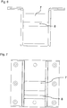
- FIG. 8 shows the transducer when installed.
- the U-shaped base member of the transducer with the two axes is embedded in a left and right protection and reinforcing element 11.1 and 11.2, to provide additional stability for the construction and to ensure the safety of the boat operator and the passengers.
- the two elements 11.1 and 11.2 are made here, for example, from seawater-resistant plastic, with wood, metal or composite materials would also be suitable.
- the boom (more specifically, the long leg of the boom, hereinafter referred to as 2) is secured to the stern of the dinghy (not shown). With its end, the hook-shaped coupling 3, this is mounted in the receiver 6, which is attached to the stern of the yacht. In this case, the cutout of the boom comes to rest on the coupling shaft 7 of the receiver 6 (not shown) at the stern of the yacht.
- Yacht and dinghy are now tail to stern and the dinghy is mounted with the boom 2 in the receiver 6.
- the boom 2 Due to the resulting forces and their directions and by the arrangement of the axes (pins) in the transducer 6 and by the shape and type of cutout in the boom 2, the boom 2 is on the coupling axis 7 when pulling up the dinghy pushed to the end of the cutout. After this horizontal, linear movement through the end of the cutout space is no longer given, the pulling movement is now implemented at the bow of the inflatable boat in a rotational movement on the coupling shaft 7 of the pickup. The bow of the dinghy is pulled up. In this case, the boom 2 moves arcuately on the coupling shaft 7 upwards.
- the outer nose of the boom 2 is now pressed against the blocking axis 8 in the transducer 6.
- the dinghy can no longer be removed from the mount by a linear movement. It can then be pulled up to about 80 degrees. Then it is completely secured.
- the S-shaped plate is bent from the rear part of the pickup 6 in such an S-shape upwards and attached to the coupling axis 7, that the nose of the hook-shaped coupling 3 in engages the locking position behind the sheet and thus prevents slipping out of the boom of the coupling axis due to a linear movement.
- the holding device shown in the figures can also be used for transport and to secure other attachments, such as, bathing platforms or brackets for solar panels, etc., where the same principle of locking can be applied.
- the exemplary explanations with reference to a dinghy served merely for a detailed description of the general principle of the holding device according to the invention and the person skilled in the art knows further embodiments and application examples for this holding device. In particular, this is not only available at the stern of a yacht, but can also be used in other areas of a yacht.
- the invention has significance for all owners of sailing or motor yachts, especially for those up to a length of about 20 meters. Through the possibility of locking "rear to rear" is a subsequent retrofitting a sailing or motor yacht with the holding device according to the invention is possible at any time.
Description
Die Erfindung betrifft eine Vorrichtung und ein Verfahren zur einfachen und sicheren Befestigung eines Geräteträgers, bevorzugt für Beiboote, an einer Segel- oder Motoryacht und zum sicheren Transport der daran befestigten Geräte während der Fahrt.The invention relates to a device and a method for easy and secure attachment of a device carrier, preferably for dinghies, on a sailing or motor yacht and for safe transport of the attached devices while driving.
Solche Geräteträger dienen insbesondere zur Befestigung und Halterung von Beibooten, mit oder ohne Motor, am Heck von Segel- oder Motoryachten, die zur Sicherheit für die Besatzung und zum sicheren Anlanden am Ufer mitgeführt werden.Such equipment carriers are used in particular for fastening and holding of dinghies, with or without motor, at the stern of sailing or motor yachts, which are carried along for safety of the crew and for safe landing on the shore.
Herkömmliche Methoden für das Mitführen eines Beibootes basieren auf folgenden Prinzipien:
- 1. Das Beiboot liegt auf dem Bug des Schiffes.
- 2. Das Beiboot liegt auf dem Kabinendach.
- 3. Das Beiboot ist mit einer Leine an die Segelyacht oder das Motorschiff angehängt, bevorzugt am Heck oder während der Hafenmanöver oft auch an der Seite mit einer Leine zur Bug- oder Mittschiffs-Klampe.
- 4. Das Beiboot wird an Davits hängend mitgeführt.
- 1. The dinghy is on the bow of the ship.
- 2. The dinghy is lying on the cabin roof.
- 3. The dinghy is attached with a leash to the sailing yacht or the motor ship, preferably at the stern or during the harbor maneuvers often also on the side with a leash to bow or midships cleat.
- 4. The dinghy is carried on davits hanging.
Sämtliche der oben genannten Mitführungsarten haben entscheidende Nachteile.All of the above-mentioned types of entrainment have significant disadvantages.
Wird das Beiboot auf dem Schiff selbst transportiert (1 und 2), wird der Skipper und die Crew in Ihrer Sicht nach vorne behindert. Abhängig von der Größe des Beibootes ist diese Sichtbehinderung aus Sicherheitsgründen eigentlich nicht zu verantworten oder behindert notwendige Manöver.If the dinghy is transported on the ship itself (1 and 2), the skipper and the crew will be obstructed in your view forward. Depending on the size of the dinghy, this visual obstruction is not responsible for safety reasons or hinders necessary maneuvers.
Ferner belegt das Beiboot wertvollen Platz auf dem naturgemäß bei Schiffen beengten Flächen. In der Regel wird das Beiboot im Bereich der Arbeitsfläche im Bugbereich abgelegt. Damit gehen mehrere Gefahren einher. Zum einen kann die Crew notwendige Arbeiten bei Problemen mit dem Vorsegel, Gennaker oder Spinnaker mangels Platz nur eingeschränkt durchführen. Zum anderen können sich das oder die Vorsegel-Leinen (Schoten) bei Segelmanövern im Beiboot verfangen.Furthermore, the dinghy occupies valuable space on the naturally crowded areas of ships. As a rule, the dinghy is stored in the area of the working area in the bow area. This is accompanied by several dangers. For one, the crew may be necessary to work on problems with the headsail, gennaker or spinnaker for lack of space only perform restricted. On the other hand, the foresail liners (pods) can get caught in sailing boats in the dinghy.
Das zu Wasser lassen beziehungsweise das Hochziehen des Beibootes ist häufig nur durch mindestens zwei Crewmitglieder durch kräfte- und zeitraubende Arbeit möglich.The launching of the dinghy is often only possible by at least two crew members by laborious and time-consuming work.
Bei der dritten Lösung wird das Beiboot durch eine Leine am Heck der Yacht vertäut. Ab ca. 20 Knoten Windgeschwindigkeit (entspricht ca. Windstärke 4) und entsprechendem Seegang, kann das Beiboot vom Wasser abheben und durch die Luft geschleudert werden wobei gegebenenfalls wichtige Teile des Schiffes beschädigt, die Crew verletzt werden oder die Zugleine reißen kann. Im schlimmsten Fall geht das Beiboot verloren.In the third solution, the dinghy is moored by a leash at the stern of the yacht. From about 20 knots wind speed (equivalent to wind force 4) and corresponding sea state, the dinghy can be lifted off the water and thrown through the air, possibly damaging important parts of the ship, injuring the crew or tearing the tug line. In the worst case, the dinghy is lost.
Beim Anhängen des Beibootes Mitschiffs oder von der Bug-Klampe aus, kann es bei größeren Wellen vorkommen, dass sich das Beiboot unter den Rumpf des Schiffes zieht und damit Schäden am Beiboot und am Rumpf der Schiffes, gegebenenfalls am Bugstrahlruder oder der Schiffsschraube, möglich sind.When attaching the dinghy of the ship or from the bow cleat, it may happen that the dinghy under the hull of the ship and thus damage the dinghy and the hull of the ship, possibly at the bow thruster or the propeller possible ,
Der notwendige Außenborder vom Beiboot muss bei diesen drei Alternativen zeitweilig abgebaut und separat verstaut werden. Ausnahmen sind eigentlich aus Sicherheitsgründen oder Umweltschutzgründen selbst bei der dritten Alternative nicht möglich.The necessary outboard of the dinghy must be temporarily dismantled in these three alternatives and stowed separately. For safety or environmental reasons, exceptions are not possible even with the third alternative.
In der vierten Lösung wäre der Außenborder zwar nicht notwendigerweise abzubauen, aber die Lösung mit Hilfe von Davits ist gegenüber den anderen Lösungen teuer und benötigt entsprechend Platz an Bord für die Davits, so dass sie praktikabel nur bei größeren Yachten und Schiffen zweckmäßig sind.While the outboard motor would not necessarily degrade in the fourth solution, the davits solution is expensive over the other solutions and requires space on board for the davits, making them practical only on larger yachts and ships.
Keiner der Yacht-Hersteller und Werften hat sich bisher dieses Problems angenommen obwohl teilweise sicherheitsrelevante Probleme entstehen können.None of the yacht manufacturers and shipyards has taken up this problem so far although some safety-related problems can arise.
Eine alternative Lösung für eine Haltevorrichtung ist in dem US Patent Nr.
Der Erfindung liegt die Aufgabe zugrunde, eine verbesserte Haltevorrichtung zu entwickeln, mit welcher ein Beiboot oder ein anderes mitzuführendes Anbauteil im Heckbereich eines Schiffes noch sicherer und einfacherer mitgeführt werden können. Erfindungsgemäß wird die Aufgabe durch eine Haltevorrichtung gemäß Anspruch 1 gelöst. Die zur Befestigung des Beibootes oder des lösbar mitzuführenden Anbaus am Schiff erforderliche Mechanik der Haltevorrichtung besteht aus zwei wesentlichen Teilen, nämlich:
- einer Anzahl von Auslegern (d.h. einer oder mehrere, bevorzugt mindestens zwei, aber auch drei oder mehrere) mit einer hakenförmigen Kupplung, die an dem Beiboot oder Anbauteil feste oder abnehmbar angebracht sind
- einer Anzahl von Aufnehmern (d.h. einer oder mehrere, bevorzugt mindestens zwei, aber auch drei oder mehrere), die mindestens eine Kupplungsachse umfassen und am Heck oder einem dort feste installierten Anbau des Schiffes so angebracht sind, dass die Ausleger mit der hakenförmigen Kupplung in die Kupplungsachse eingehängt und durch Drehung des Auslegers oder des Aufnehmers um die Kupplungsachse ab einem bestimmten Drehwinkel wie in
Anspruch 1 definiert arretiert werden.
- a number of cantilevers (ie, one or more, preferably at least two, but also three or more) with a hook-shaped coupling fixedly or removably attached to the dinghy or attachment
- a number of transducers (ie one or more, preferably at least two, but also three or more) comprising at least one coupling axis and are mounted at the rear or fixed there fixed attachment of the ship so that the boom with the hook-shaped coupling in the Mounted coupling axis and locked by rotation of the boom or the transducer about the coupling axis from a certain angle of rotation as defined in
claim 1.
Bei mehreren Aufnehmern werden diese gemäß einer bevorzugten Ausführungsform im gleichen Abstand montiert wie die Ausleger am Beiboot oder einem mitzuführenden Anbauteil, so dass jeweils ein Ausleger in ein korrespondierendes Anbauteil eingreifen kann. Wenn mehr Aufnehmer als Ausleger im System beinhaltet sind, werden diese bevorzugt so angeordnet, dass mindestens zwei Ausleger in zwei korrespondierende Aufnehmer eingreifen können. Die freien Aufnehmer können entweder für weitere Anbauteile verwendet werden oder dienen zur unterschiedlichen Positionierung des Beibootes oder des mitzuführenden Anbauteils.In the case of several receivers, according to a preferred embodiment, they are mounted at the same distance as the outriggers on the dinghy or an accessory to be carried, so that in each case one jib can engage in a corresponding attachment. If more transducers than cantilevers are included in the system, they are preferably arranged so that at least two cantilevers can engage in two corresponding transducers. The free transducers can either be used for additional attachments or serve for the different positioning of the dinghy or the attached attachment.
Alternativ zu der vorhergehenden Ausführungsform ist es auch möglich, zwei oder mehrere Ausleger in einen Aufnehmer einzuhängen, wenn dieser zum Beispiel als eine Einzelstange ausgebildet ist, in die mehrere Ausleger gleichzeitig eingreifen können.As an alternative to the previous embodiment, it is also possible to mount two or more arms in a pick-up, if it is designed, for example, as a single rod, in which several arms can engage simultaneously.
Hierzu kann der Aufnehmer zum Beispiel aus einem Rohr beziehungsweise einer Stange mit 10 bis 100 cm Länge, bevorzugt etwa 10 bis 20 cm für eine Kupplung von einzelnen Auslegern bzw. etwa 50 bis 100 cm, insbesondere etwa 60 bis 70 cm, für die Kupplung von zwei oder mehreren Auslegern in die gleiche Stange sein. Diese Ausführungsvariante ist billiger zu produzieren, einfacher am Schiff zu befestigen und vielfältiger nutzbar, als einzelne, speziell in der Breite an die Ausleger angepasste Aufnehmer und haben die gleiche Funktionalität. Jedoch kann durch den fehlenden seitlichen Halt, die Fixierung des Beibootes oder der Anbauten etwas unsicherer werden, wobei die generelle Arretierung ebenso geleistet werden kann.For this purpose, the transducer, for example, from a tube or a rod with 10 to 100 cm in length, preferably about 10 to 20 cm for a coupling of individual arms or about 50 to 100 cm, in particular about 60 to 70 cm, for the coupling of two or more outriggers to be in the same pole. This variant is cheaper to produce, easier to attach to the ship and more versatile than single, especially in width to the boom adapted transducers and have the same functionality. However, due to the lack of lateral support, the fixation of the Dinghy or attachments are somewhat uncertain, the general locking can be done as well.
Das allgemeine Prinzip der erfindungsgemäßen Haltevorrichtung wird im Folgenden an Hand des Mitführens eines Beibootes detaillierter beschrieben, ohne die Haltevorrichtung auf diese Anwendung zu beschränken. Das Heck des Beibootes wird entweder direkt oder durch Verwendung einer Leine hochgehoben und die Ausleger werden in die Aufnehmer an dem Schiff, insbesondere einer Motor- oder Segelyacht (im Folgenden auch einfach "Yacht" genannt) eingehakt. Wie sich bei der Beschreibung zeigen wird, eignet sich dieses Prinzip insbesondere für kleinere Yachten, zum Beispiel Yachten mit einer Länge von bis zu 20 Metern.The general principle of the holding device according to the invention will be described in more detail below with reference to the entrainment of a dinghy, without limiting the holding device to this application. The stern of the dinghy is lifted either directly or by use of a leash and the outriggers are hooked into the receivers on the ship, in particular a motor or sailing yacht (hereafter simply referred to as "yacht"). As will be shown in the description, this principle is particularly suitable for smaller yachts, for example, yachts with a length of up to 20 meters.
Die Aufnehmer an der Yacht haben zwei wesentliche Vorteile. Durch die Konstruktion ergibt sich eine Art Fanghaken, der es erlaubt, die Ausleger ohne großen Kraftaufwand auf die Aufnehmer zu legen und in die Kupplungsachsen einzuhängen. Damit ist das Beiboot schon mal vorläufig an der Yacht gesichert.The pickups on the yacht have two major advantages. The construction results in a kind of fishing hook, which allows to lay the boom without much effort on the pick-up and mount in the coupling axles. Thus, the dinghy is ever provisionally secured to the yacht.
Über einen im achterlichen Bereich oder am Masten des aufnehmenden Schiffes und am Bug des Beibootes angebrachten Seilzug wird das Beiboot mit dem Bug voran in eine annähernd aufrechte Position gezogen. Das Beiboot ist somit an seinem Heck mit dem Heck der aufnehmenden Yacht verbunden. Mit dem Bug steht es in einem Winkel zwischen 45° und 90° nach oben.The dinghy is towed forward in an approximately upright position via a cable pull in the aft area or on the mast of the receiving ship and at the bow of the dinghy. The dinghy is thus connected at the rear with the stern of the receiving yacht. With the bow it stands at an angle between 45 ° and 90 ° upwards.
Durch die Form und Art der hakenförmigen Kupplung im Ausleger wird beim Hochziehen des Beibootes zunächst das Beiboot mit dem daran montierten Ausleger auf der Hauptachse bis zum Anschlag der hakenförmigen Kupplung geschoben. Dann wird das Beiboot an seinem Bug nach oben gezogen. Dabei bewegt sich der Bug des Beibootes bogenförmig zusammen mit dem Ausleger auf der Hauptachse nach oben und die hakenförmige Kupplung dreht sich um die Kupplungsachse in eine Arretierungsposition, in der ein Herausrutschen der hakenförmigen Kupplung von der Kupplungsachse verhindert ist. Das Gewicht des Beibootes und die spezielle Konstruktion der hakenförmigen Kupplung der Ausleger beziehungsweise der Aufnehmer führen zu einer sehr festen Verbindung von Ausleger und Aufnehmer in der Arretierungsposition. Selbst bei hohen Windstärken bis ca. 35 Knoten konnte kein Problem festgestellt werden. Auch bei mechanischer Belastung der Kupplung durch, z.B. Wind, Wellengang, Kränkung oder sonstige Einflüsse lässt sich das Beiboot am Heck in der Arretierungsposition nicht mehr bewegen. Es ist somit sicher und fest arretiert.Due to the shape and type of hook-shaped coupling in the boom when pulling the dinghy first the dinghy is pushed with the boom mounted on the main axis to the stop of the hook-shaped coupling. Then the dinghy is pulled up at its bow. In this case, the bow of the dinghy moves arcuately together with the boom on the main axis upwards and the hook-shaped coupling rotates about the coupling axis in a locking position in which slipping out of the hook-shaped coupling is prevented by the coupling axis. The weight of the dinghy and the special design of the hook-shaped coupling of the boom or the transducer lead to a very firm connection of the boom and the transducer in the locking position. Even with high wind forces up to about 35 knots no problem could be determined. Also with mechanical load of the clutch by, eg wind, swell, Kränkung or other influences, the dinghy can not be moved at the rear in the locking position. It is thus secure and firmly locked.
Durch die feste Arretierung und die einfache Mechanik ist es nunmehr auch möglich, schwere Beiboote (z.B. größer 70 kg) zu verwenden oder einen Motor (z.B. Außenborder) am Beiboot zu belassen, währen das Beiboot in der erfindungsgemäßen Haltevorrichtung transportiert wird.By virtue of the fixed lock and the simple mechanism, it is now also possible to use heavy dinghies (for example greater than 70 kg) or to leave an engine (for example outboard motor) on the dinghy while the dinghy is being transported in the holding device according to the invention.
Die erfindungsgemäße Haltevorrichtung erlaubt es, das Beiboot durch wenige Handgriffe, durchgeführt in umgekehrter Reihenfolge wieder zu Wasser zu lassen. Wenn heute dazu ein Aufwand von zwei Crew-Mitgliedern, viel Kraft und Zeit notwendig ist, so ermöglicht die erfindungsgemäße Haltevorrichtung dies in wenigen Minuten durch eine Person nahezu ohne Krafteinsatz. Die Kraftanstrengung ist dabei deutlich geringer und der Vorgang ist auch von körperlich schwächeren Crew-Mitgliedern leicht durchzuführen.The holding device according to the invention allows the dinghy by a few steps, carried out in reverse order to water again. If today an effort of two crew members, a lot of strength and time is necessary, so the holding device according to the invention allows this in a few minutes by a person with almost no use of force. The effort is much less and the process is easy to perform even by physically weaker crew members.
Das Mitführen eines Beibootes am Heck der Yacht behindert nicht mehr die Sicht des Skippers und der Crew, da es nicht mehr auf dem Bug oder Kabinendach in direkter Sichtverbindung nach vorne liegt.The carrying of a dinghy at the stern of the yacht no longer obstructs the view of the skipper and the crew, as it is no longer on the bow or canopy in direct line of sight forward.
Da das Beiboot nicht mehr auf Deck gehievt bzw. nicht mehr vom Deck über den Seezaun zu Wasser gelassen werden muss, ist das Risiko des Zerstörens des Seezaunes oder des Beibootes während des Handlings des Beiboots aufgehoben.Since the dinghy is no longer hoisted on deck or no longer needs to be launched from the deck over the sea fence, the risk of destroying the sea fence or dinghy during the handling of the dinghy is lifted.
Das Risiko des Verlustes des Beibootes wird deutlich reduziert. Es ist sicher befestigt und wird auch durch höhere Windstärken nicht vertrieben. Dabei wird auch die Verletzungsgefahr oder Beschädigungsgefahr bei Sturm durch ein durch die Luft geschleudertes Beiboot verringert.The risk of losing the dinghy is significantly reduced. It is securely fastened and is not driven by higher wind forces. The risk of injury or damage in case of storm is reduced by a dinghy flung through the air.
Der ohnehin auf dem Schiff nur begrenzte Raum beziehungsweise die für Manöver erforderliche Arbeitsfläche wird durch das Beiboot nicht weiter reduziert. Ein Verfangen der Schoten am Beiboot während eines Segelmanövers ist ausgeschlossen.The only limited on the ship space or required for maneuver work surface is not further reduced by the dinghy. A catching of the pods on the dinghy during a sailing maneuver is excluded.
Durch die vorstehend beschriebene einfache Bedienbarkeit und sichere Arretierungsmöglichkeit der erfindungsgemäßen Haltevorrichtung kann diese gemäß einem weiteren Gesichtspunkt der Erfindung auch für Zusatzanwendungen an Schiffen, insbesondere Motor- und Segelyachten, verwendet werden. Dabei können die Ausleger zur Halterung von Geräteträgern für Bade- oder Angelplattformen, Grillplattformen, Fahrrad-oder Zweiradträger (z. B. für leichte Mofas oder elektrische Fahrräder), Solarpanels, Tischen und ähnlichen Geräten verwendet werden. Das zugrundeliegende Prinzip ist das gleiche wie vorstehend zur Halterung eines Beibootes am Heck einer Yacht beschrieben wurde. Dabei können diese Halterungen auch für die Halterung von Anbauteilen, zum Beispiel im Bugbereich oder Seitenbereich eines Schiffes, eingesetzt werden. Der Vorteil liegt darin, dass die Haltevorrichtung vielfältig einsetzbar ist, die Anbauten außenbords mitgeführt und sicher gehalten werden können. So kann zum Beispiel bei Verwendung einer Plattform als Grillplattform ein Grill (z.B. typischer Gas-Grill der Firma Weber) komplett außenbords verwendet werden und nach Gebrauch wieder an Bord verstaut werden. Diese Maßnahme erhöht die Sicherheit bei dessen Verwendung.Due to the above-described simple operability and secure locking possibility of the holding device according to the invention, this can be used according to a further aspect of the invention also for additional applications on ships, especially motor and sailing yachts. Here, the boom for Bracket for bath or fishing platforms, barbeque platforms, bicycle or two-wheel carriers (eg for light mopeds or electric bicycles), solar panels, tables and similar equipment. The underlying principle is the same as described above for holding a dinghy at the stern of a yacht. These brackets can also be used for mounting attachments, for example in the bow area or side area of a ship. The advantage is that the holding device can be used in a variety of ways, that the attachments can be carried outboard and held securely. For example, when using a platform as a grill platform a grill (eg typical Weber gas grill) can be used completely outboard and stowed back on board after use. This measure increases the safety in its use.
Weitere erfindungsgemäße Ausgestaltungen ergeben sich aus der nachstehenden Beschreibung von bevorzugten Ausführungsformen der erfindungsgemäßen Haltevorrichtung.Further embodiments of the invention will become apparent from the following description of preferred embodiments of the holding device according to the invention.
Erfindungsgemäß weisen die Aufnehmer zusätzlich zur Kupplungsachse eine Blockiervorrichtung, wie zum Beispiel eine Blockierachse oder ein Blockierblech auf. Die Blockiervorrichtung greift beispielsweise in die hakenförmige Kupplung ein und verhindert eine lineare Bewegung des jeweiligen Auslegers im Arretierungszustand, bevorzugt nach einer Drehung des Auslegers um etwa 25 bis 40 Grad aus der Horizontalen, weiter bevorzugt um etwa 27 bis etwa 35, insbesondere ab etwa 30 Grad. Beispielsweise ist die Blockiervorrichtung durch die Drehung dann so weit in die Aussparung der hakenförmigen Kupplung am Ausleger eingetreten, dass sie bei einer linearen Bewegung an die Nase der hakenförmigen Kupplung anstoßen würde und somit ein Herausrutschen der hakenförmigen Kupplung aus der Kupplungsachse verhindert. Der Drehwinkel, ab dem eine solche Blockade eintreten soll, kann durch die Position der Blockiervorrichtung, zum Beispiel bei einer bevorzugt parallel zur Kupplungsachse angebrachten Blockierachse, oder durch die besondere Form des Blockierblechs, bevorzugt eine S-Form, die sich vom rückwandigen Teil des Aufnehmers nach oben schlängelt und an der Kupplungsachse befestigt ist, bestimmt werden. Die vorstehenden Werte für die Drehung bis zur Blockierung sind lediglich bevorzugte Werte, die für andere Anwendungen wie spezielle Anbauten oder Beiboote auch entsprechend kleiner oder größer gewählt werden können.According to the invention, the receivers in addition to the coupling axis on a blocking device, such as a blocking axis or a blocking plate. The blocking device intervenes, for example, in the hook-shaped coupling and prevents linear movement of the respective arm in Arretierungszustand, preferably after rotation of the boom by about 25 to 40 degrees from the horizontal, more preferably by about 27 to about 35, in particular from about 30 degrees , For example, the blocking device has then entered the recess of the hook-shaped coupling on the boom so far that it would abut the nose of the hook-shaped coupling in a linear movement and thus prevents slipping out of the hook-shaped coupling from the coupling axis. The angle of rotation, from which such a blockage should occur, by the position of the blocking device, for example in a preferably parallel to the coupling axis mounted blocking axis, or by the particular shape of the blocking plate, preferably an S-shape extending from the rear wall portion of the pickup snaking upwards and attached to the coupling axle, to be determined. The above values for rotation to stall are merely preferred values which may be chosen to be smaller or larger for other applications such as special attachments or dinghies.
Gemäß einem weiteren Gesichtspunkt der erfindungsgemäßen Haltevorrichtung ist diese so ausgestaltet, dass das Beiboot oder Anbauteil während der Fahrt mittels eines an einem von den Befestigungspunkten der Ausleger beabstandeten Punkt befestigten Seilzug in Arretierungsposition, bevorzugt in einem Drehwinkel zwischen 30 und 90 Grad, bezogen auf die horizontale Lage des Beibootes oder Anbauteils, gehalten wird. Um ein zufälliges Herausrutschen aus der Kupplungsachse zu verhindern, ist es bevorzugt, dass der Drehwinkel etwas größer als der kleinste zur Sicherung geeignete Drehwinkel ist.According to a further aspect of the holding device according to the invention this is designed so that the dinghy or attachment during travel by means of a fixed at one of the attachment points of the boom point fixed cable in locking position, preferably in a rotation angle between 30 and 90 degrees, relative to the horizontal Location of the dinghy or attachment, is held. In order to prevent accidental slipping out of the coupling axis, it is preferred that the angle of rotation is slightly greater than the smallest angle of rotation suitable for securing.
Die erfindungsgemäße Haltevorrichtung kann gemäß einem weiteren Gesichtspunkt Ausleger jeweils auf der Steuerbord- und Backbord-Seite des Heckspiegels des Beibootes aufweisen, die mit der hakenförmigen Kupplung vom Beiboot weg zeigend angebracht sind. Durch die Verwendung von zwei Auslegern und entsprechenden Aufnehmern kann eine verbesserte Stabilität erreicht werden. Dies ist insbesondere bei schwereren oder weit ausreichenden Anbauten zweckmäßig. Bei Verwendung eines Außenborders kann dieser zwischen den beiden Auslegern angebracht werden und ist auch bei am Beiboot fest montierten Auslegern funktionsfähig. Um genügend Platz für einen Außenborder zu schaffen, werden die Ausleger bevorzugt in einem Abstand, von der Mitte des Beibootes aus gesehen, von zwischen 25 cm und 50 cm nach links und rechts angeordnet. So ergibt sich ein Abstand der beiden Ausleger von etwa 50 cm bis 100 cm, je nach Breite des Beibootes. Weiter bevorzugt ist der vertikale Abstand zum Beispiel auf 70 cm normiert, um ein austauschbares Haltesystem zu schaffen, in dem mehrere Beiboote oder Anbauteile austauschbar mit dem gleichen System verwendet werden können. Die Austauschbarkeit und eine Norm von 70 cm gewährleisten die Verwendung des Systems mit allen heute gängigen Beibooten mit Spiegel.According to a further aspect, the holding device according to the invention can have outriggers each on the starboard and port side of the transom of the dinghy, which are attached pointing away from the dinghy with the hook-shaped coupling. By using two cantilevers and corresponding transducers, improved stability can be achieved. This is particularly useful for heavier or far-reaching crops. When using an outboard, it can be mounted between the two outriggers and will work even if the jib is fixed to the dinghy. To provide sufficient space for an outboard, the booms are preferably located at a distance, viewed from the center of the dinghy, of between 25 cm and 50 cm to the left and right. This results in a distance of the two arms of about 50 cm to 100 cm, depending on the width of the dinghy. More preferably, for example, the vertical distance is normalized to 70 cm to provide a replaceable holding system in which multiple dinghies or attachments can be used interchangeably with the same system. The interchangeability and a standard of 70 cm ensure the use of the system with all currently common dinghy with mirror.
Für die Befestigung am Spiegel eines Beibootes ist eine L-förmige Konstruktion der Ausleger zweckmäßig, wobei der kleinere Schenkel bevorzugt feste oder abnehmbar mit dem Spiegel verbunden ist und der längere Schenkel die hakenförmige Kupplung aufweist. Beide Schenkel schließen bevorzugt einen Winkel von etwa 80 und 90 Grad ein, so dass der längere Schenkel bevorzugt in etwa in der Horizontalen vom Spiegel des Beibootes wegweist. Für gängige Schlauchboote beträgt der Winkel etwa 83 Grad.For attachment to the mirror of a dinghy L-shaped construction of the boom is expedient, the smaller leg is preferably fixed or removable connected to the mirror and the longer leg has the hook-shaped coupling. Both legs preferably include an angle of about 80 and 90 degrees, so that the longer leg preferably points away from the mirror of the dinghy approximately in the horizontal. For common inflatable boats, the angle is about 83 degrees.
Die Höhe, in welcher die beiden Ausleger angebracht werden, ist beim schwimmenden Beiboot ungefähr in der Höhe der Wasserfläche oder etwas darüber.The height at which the two outriggers are attached is approximately equal to or slightly above the water surface of the floating dinghy.
Beispielhafte Materialien für die Ausleger bestehen aus Vierkantmaterial oder abgerundetem Vierkantmaterial oder Vierkant-Rohren aus Kunststoff, Karbonfaser-Material, Aluminium, Edelstahl oder Stahlblechen, um eine entsprechende Stabilität zu gewährleisten. Die Kanten sind dabei bevorzugt abgerundet, da dadurch die Stabilität der Konstruktion weiter erhöht werden kann. Alternativ können auch Rohre in runder oder ovaler Form oder U- bzw. I-förmige Trägerelemente für die Ausleger verwendet werden. Um zum Beispiel die Stabilität und die Funktionalität der hakenförmigen Kupplung zu gewährleisten, kann optional an den Enden eines solchen Auslegers ein Vierkantrohr aufgeschweißt werden.Exemplary boom materials are square or rounded square or square plastic, carbon fiber, aluminum, stainless steel or sheet steel tubing to provide stability. The edges are preferably rounded, since thereby the stability of the construction can be further increased. Alternatively, pipes in round or oval shape or U- or I-shaped support elements for the boom can be used. For example, to ensure the stability and functionality of the hook-shaped coupling, optionally a square tube can be welded to the ends of such a boom.
Weiter bevorzugt können die Ausleger einen verlängerbaren Auslegerarm (längerer Schenkel) aufweisen, der aus zwei zusammensteckbaren und miteinander fixierbaren Formrohrteilen aufgebaut ist und an dessen Ende die hakenförmige Kupplung angeordnet ist. Am kurzen Schenkel weisen diese eine Befestigungseinheit für die Anbringung am Spiegel eines Beibootes auf. Durch die Verwendung von zusammensteckbaren Auslegerarmelementen kann die Länge des Auslegers auf die baulichen Gegebenheiten des Beibootes angepasst werden. Durch die mögliche Verschiebung und Arretierung, wie zum Beispiel mittels herkömmlicher Schnapp- oder Steckverschlüsse, sonstigen Schnellverschlüssen oder festen Arretierungsmöglichkeiten, des langen Schenkels des Auslegers kann der Abstand des Beibootes auch während des Transports eingestellt werden, zum Beispiel, um am Heck mehr Platz zu schaffen oder um mit dem Heck näher ans Kai heranfahren zu können.More preferably, the boom can have an extendable arm (longer leg), which is composed of two mating and fixable together with each other mold tube parts and at the end of the hook-shaped coupling is arranged. On the short leg, these have a mounting unit for attachment to the mirror of a dinghy. Through the use of clip-arm boom elements, the length of the boom can be adapted to the structural conditions of the dinghy. Due to the possible displacement and locking, such as by means of conventional snap or snap fasteners, other snap fasteners or fixed locking options, the long leg of the boom, the distance of the dinghy can also be adjusted during transport, for example, to create more space at the rear or to get closer to the quayside with the stern.
Gemäß einer bevorzugten Ausführungsform der erfindungsgemäßen Haltevorrichtung kann der oder die Aufnehmer aus einem U-förmigen Grundbauteil aus Kunststoff, Karbonfaser-Verbundmaterial, Aluminium, Edelstahl oder Stahlblech bestehen, das feste oder drehbar gelagert mit dem Schiff verbunden ist. Wenn das Grundbauteil des Aufnehmers drehbar gelagert ist, dient die Drehung zur Arretierung des eingehängten Auslegers wie vorstehend beschrieben ist. Dabei ist nach der Drehung des Grundbauteils des Aufnehmers in eine Arretierungsposition dieses ebenfalls zu arretieren, um eine Sicherung der Kupplung des Aufnehmers mit dem Ausleger zu gewährleisten. Bei Drehung des Auslegers um einen festen Aufnehmer hingegen übernimmt zum Beispiel die Halteleine am Bug des Beibootes diese Sicherungsfunktion.According to a preferred embodiment of the holding device according to the invention, the one or more receivers of a U-shaped base member made of plastic, carbon fiber composite material, aluminum, stainless steel or sheet steel, which is fixed or rotatably mounted connected to the ship. When the base member of the susceptor is rotatably supported, the rotation serves to lock the hinged arm as described above. In this case, after the rotation of the basic component of the pickup in a locking position this also to lock, to ensure a backup of the coupling of the pickup with the boom. When the boom is rotated about a fixed receiver, however, for example, the tether on the bow of the dinghy takes over this security function.
Bevorzugt weist das U-förmige Grundbauteil mindestens eine Kupplungsachse und mindestens eine Blockierachse oder mindestens ein Blockierblech zwischen den beiden Seitenteilen auf, wobei der Ausleger mit der hakenförmigen Kupplung in die Kupplungsachse drehbar eingehängt ist. Die Anordnung der Kupplungsachse und der Blockierachse im Aufnehmer sind an die Form und Ausfräsung des hakenförmigen Kupplungsteils angepasst, so dass nach einer Drehung von etwa 30 Grad, die Blockierachse ein Herausrutschen des hakenförmigen Kupplungsteils des Auslegers aus der Kupplungsachse des Aufnehmers verhindert. Beispielsweise blockiert die Blockierachse oder das Blockierblech eine lineare Bewegung des Kupplungsteils in der Arretierungsposition, erlaubt diese Bewegung aber im nicht gedrehten Zustand (Ausgangszustand beim Einhängen des Auslegers in den Aufnehmer).Preferably, the U-shaped base member has at least one coupling axis and at least one locking axis or at least one blocking plate between the two side parts, wherein the boom is hooked with the hook-shaped coupling in the coupling axis rotatable. The arrangement of the coupling axis and the blocking axis in the pickup are adapted to the shape and cutout of the hook-shaped coupling part, so that after a rotation of about 30 degrees, the blocking axis prevents slipping out of the hook-shaped coupling part of the boom from the coupling axis of the pickup. For example, blocks the blocking axis or the blocking plate a linear movement of the coupling part in the locking position, but allows this movement in the non-rotated state (initial state when mounting the boom in the transducer).
Für ein zweckmäßige Anordnung der Haltevorrichtung, insbesondere für den Transport eines Beibootes oder einer Badeplattform, ist es vorteilhaft, wenn der oder die Aufnehmer entweder außen am Heck oder versenkt im Heck des Schiffes angebracht sind, da sie dadurch bei den meisten Manövern nicht im Weg sind und dadurch die Verletzungsgefahr verringert wird. Dabei können die Aufnehmer entweder direkt am Schiff befestigt werden oder sie werden an eine bereits bestehende Plattform im Heckbereich montiert. Wenn sie direkt am Heck oder auf einer Plattform montiert werden, können sie mit einem Schutz-und Verstärkungselement, z.B. aus Holz oder Kunststoff, ummantelt sein, um Verletzungen zu verhindern bzw. um Beschädigungen zu vermeiden. Dazu können die U-förmigen Grundbauteile ummantelt werden oder direkt in einer Versenkung am Heck, z.B. einer Heckklappe, angebracht werden, so dass nur Aussparungen mit der Kupplungsachse und der optionalen Blockierachse frei liegen, in die die Ausleger eingehängt werden.For a convenient arrangement of the holding device, in particular for the transport of a dinghy or a bathing platform, it is advantageous if the one or more transducers are mounted either outside the rear or sunk in the stern of the ship, as they are thereby in most maneuvers out of the way and thereby the risk of injury is reduced. The transducers can either be attached directly to the ship or they can be mounted on an existing platform in the rear area. When mounted directly on the stern or on a platform, they may be provided with a protective and reinforcing element, e.g. made of wood or plastic, be sheathed to prevent injury or to prevent damage. For this purpose, the U-shaped basic components can be encased or directly in a sinking at the rear, e.g. a tailgate, are mounted so that only recesses are exposed with the coupling axis and the optional locking axis, in which the arms are mounted.
Die Herstellung erfolgt zum Beispiel durch Unternehmen in der Metall-, Kunststoff-, Kohlefaser-Verbundwerkstoffe- und Holz-Branche. Nach Fertigstellung der Metallteile werden diese durch ein geeignetes Verfahren gegen Umwelteinflüsse (insbesondere Seewasser) behandelt, z.B. eloxiert. Einige Elemente der Erfindung können entweder aus Aluminium, Edelstahl, Stahl, Kohlefaser-Verbundwerkstoffen, Holz oder aus schlagfestem Kunststoff sein, sofern sie seewasserbeständig (Salzwasser) sind.Manufactured by, for example, companies in the metal, plastics, carbon fiber composites and wood industries. After completion of the metal parts, they are treated by a suitable process against environmental influences (in particular seawater), e.g. anodized. Some elements of the invention may be either aluminum, stainless steel, steel, carbon fiber composites, wood or impact resistant plastic as long as they are seawater resistant (salt water).
Im Folgenden wird die erfindungsgemäße Haltevorrichtung an Hand von Figuren beschrieben, wobei für gleiche Bauelemente die gleichen Bezugszeichen verwendet werden. Die Figuren sind lediglich zur Erläuterung gedacht, ohne die Erfindung auf spezielle Ausführungen einzuschränken. Auch die Dimensionen sind beispielhafte Veranschaulichen des allgemeinen Prinzips der Erfindung.
Figur 1- zeigt eine Anwendungsmöglichkeit der erfindungsgemäßen Haltevorrichtung.
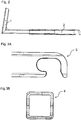
Figur 2- zeigt eine Seitenansicht eines Auslegers.
- Figur 3A
- zeigt eine Vergrößerung der hakenförmigen Kupplung des Auslegers aus
Fig. 2 . - Figur 3B
- zeigt die Vorderansicht des Auslegers aus
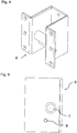
Fig. 2 . Figur 4- zeigt eine räumliche Darstellung eines Aufnehmers.
- Figur 5
- zeigt den Aufnehmer aus
Fig. 4 in der Seitendarstellung. Figur 6- zeigt den Aufnehmer aus
Fig. 4 von unten. Figur 7- zeigt den Aufnehmer aus
Fig. 4 von vorne. Figur 8- zeigt den Aufnehmer im eingebauten Zustand.
Figur 9- zeigt eine Seitenansicht des Auslegers im Aufnehmer im Arretierungszustand.
- Figur 10
- zeigt einen alternativen Aufnehmer in der Seitendarstellung.
- FIG. 1
- shows an application of the holding device according to the invention.
- FIG. 2
- shows a side view of a boom.
- FIG. 3A
- shows an enlargement of the hook-shaped coupling of the boom
Fig. 2 , - FIG. 3B
- shows the front view of the boom
Fig. 2 , - FIG. 4
- shows a spatial representation of a pickup.
- FIG. 5
- shows the pickup
Fig. 4 in the page presentation. - FIG. 6
- shows the pickup
Fig. 4 from underneath. - FIG. 7
- shows the pickup
Fig. 4 from the front. - FIG. 8
- shows the transducer when installed.
- FIG. 9
- shows a side view of the boom in the receiver in Arretierungszustand.
- FIG. 10
- shows an alternative pickup in the page view.
In der
Der am Beiboot zu befestigende Teil der erfindungsgemäßen Haltevorrichtung wird als Ausleger bezeichnet.
Der hier gezeigte Ausleger besteht aus zwei Teilen. Ein Teil des Auslegers wird aus zwei einzelnen Stücken zu einem nahezu rechtwinkligen, L-förmigen Teil zusammengebaut. Dabei werden quadratische (hier gezeigt), runde oder rechteckige Formrohre verwendet. Dieser Teil wird als Befestigungsschenkel 1 bezeichnet.The boom shown here consists of two parts. A part of the boom is assembled from two separate pieces into a nearly rectangular, L-shaped part. In this case, square (shown here), round or rectangular shaped tubes are used. This part is called mounting
Der zweite Teil des Auslegers verlängert einen Teil des L-förmigen Befestigungsschenkels 1. Dieser Teil wird ebenfalls aus quadratischen (hier gezeigt), runden oder rechteckigen Formrohren produziert und dient zur einfachen Längenverstellung. Dazu sind die beiden Teile des Auslegers ineinander schiebbar ausgestaltet. Durch die mögliche Verschiebung des beweglichen Teils des Auslegers kann der Abstand zur Yacht eingestellt werden. Der verlängernde Teil des Auslegers wird auch als langer Schenkel 2 bezeichnet und umfasst an seinem Ende die hakenförmige Kupplung 3. Beide Teile 1 und 2 bilden zusammen den Ausleger.The second part of the boom extends part of the L-shaped mounting
Die hakenförmige Kupplung 3 ist in
Der zum Ausleger passende Aufnehmer 6 wird am Heck der Yacht festgemacht (siehe
Beide Achsen können unterschiedliche Dicken und eine ganz bestimmte Anordnung haben. Die Kupplungsachse 7 muss die Last des Beibootes tragen und ist deshalb in drei bis vierfacher Stärke im Vergleich zur Blockierachse 8 ausgeführt. Die Blockierachse dient der Arretierung, das heißt verhindert eine lineare Verschiebung des Auslegers in der Arretierungsposition, und trägt keine Last. Deshalb kann sie dünner als die Kupplungsachse sein. Die Blockierachse 8 befindet sich in einem bestimmten Abstand und Winkel zur Hauptachse, damit eine Arretierung beim Drehen des eingehängten Auslegers zustande kommen kann. Hierauf wird später noch detaillierter eingegangen.Both axes can have different thicknesses and a specific arrangement. The
Die
In der
Der Ausleger (genauer gesagt der lange Schenkel des Auslegers, der im Folgenden mit 2 bezeichnet wird) ist am Heck des Beibootes (nicht gezeigt) festgemacht. Mit seinem Ende, der hakenförmigen Kupplung 3, wird dieser in den Aufnehmer 6, der am Heck der Yacht angebracht ist, eingehängt. Dabei kommt die Ausfräsung des Auslegers auf der Kupplungsachse 7 des am Heck der Yacht (nicht gezeigt) angebrachten Aufnehmers 6 zum Liegen. Yacht und Beiboot stehen nun Heck an Heck und das Beiboot ist mit dem Ausleger 2 im Aufnehmer 6 eingehängt.The boom (more specifically, the long leg of the boom, hereinafter referred to as 2) is secured to the stern of the dinghy (not shown). With its end, the hook-shaped
Als nächster Schritt wird nun versucht, durch eine Leine am Bug des Beibootes, dieses durch Zug an der Beiboot-Bugleine nach oben zu ziehen. Die Leine kann dabei vom Bug des Beibootes in Richtung Mastspitze und von dort über einen Winch ins Cockpit des Schiffes laufen. Dort kann die Drehposition des Beibootes unter Zuhilfenahme des Winches bestimmt werden. Sollte bei Yachten keine Dirk zur Verfügung stehen, so kann ein am Achterstag vertäuter Seilzug hierfür verwendet werden.The next step is to try to pull it up by pulling on the bow of the dinghy with a leash at the bow of the dinghy. The leash can run from the bow of the dinghy towards the top of the mast and from there via a winch into the cockpit of the ship. There, the rotational position of the dinghy can be determined with the help of Winches. If no Dirk is available for yachts, then a winch that has been moored on the backstay can be used for this purpose.
Durch die sich ergebenden Kräfte sowie deren Richtungen und durch die Anordnung der Achsen (Pins) im Aufnehmer 6 und durch die Form und Art der Ausfräsung im Ausleger 2, wird beim Hochziehen des Beibootes, zunächst der Ausleger 2 auf der Kupplungsachse 7 bis zum Ende der Ausfräsung geschoben. Nachdem dieser horizontalen, linearen Bewegung durch das Ende der Ausfräsung kein Raum mehr gegeben wird, wird nun die Zugbewegung am Bug des Schlauchbootes in eine Drehbewegung auf der Kupplungsachse 7 des Aufnehmers umgesetzt. Der Bug des Beibootes wird nach oben gezogen. Dabei bewegt sich auch der Ausleger 2 bogenförmig auf der Kupplungsachse 7 nach oben.Due to the resulting forces and their directions and by the arrangement of the axes (pins) in the
Die äußere Nase des Auslegers 2 wird nun gegen die Blockierachse 8 im Aufnehmer 6 gedrückt. Je größer der bogenförmige Winkel, relativ zur Horizontalen, ist, desto weiter wird nun die Nase am Ausleger in die Blockierachse des Aufnehmers gedreht. Ist das Schlauchboot in einer Stellung von circa 30 Grad zur Horizontalen (ungefähre Position in
Die Blockierachse 8 dient zur Verhinderung der linearen Bewegung des in die Kupplungsachse 7 eingehängten Auslegers 2, die insbesondere bei Wind, Wellenschlag, Kränkung des Schiffes oder anderen Schlägen auf das Boot auf den Ausleger übertragen werden. Durch die Arretierung mit Hilfe der Blockierachse 8 ist diese lineare Bewegung aber verhindert, so dass mit einfachen Mitteln eine deutlich erhöhte Sicherheit gegenüber einer lediglich auf dem Schwerkraftprinzip beruhenden Sicherung (z.B. ohne zweite Achse) gewährleistet wird.The blocking
Alternativ zu der vorstehend aufgeführten Haltevorrichtung mit zwei Achsen, nämlich einer Kupplungsachse und einer Blockierachse im Aufnehmer, kann die erfindungsgemäße Haltevorrichtung anstelle der Blockierachse ein Blech zum Arretieren der Ausleger besitzen. Die
Die in den Figuren dargestellte Haltevorrichtung kann auch zum Transport und zur Sicherung von anderen Anbauteilen, wie zum Beispiel, Badeplattformen oder Halterungen für Solarpanels usw. eingesetzt werden, wobei das gleich Prinzip der Arretierung angewendet werden kann. Die beispielhaften Erläuterungen an Hand eines Beibootes dienten lediglich zur detaillierten Beschreibung des allgemeinen Prinzips der erfindungsgemäßen Haltevorrichtung und der Fachmann kennt weitere Ausgestaltungen und Anwendungsbeispiele für diese Haltevorrichtung. Insbesondere ist diese nicht nur am Heckbereich einer Yacht nutzbar, sondern kann auch in anderen Bereichen einer Yacht eingesetzt werden. Die Erfindung besitzt Bedeutung für alle Besitzer von Segel- oder Motoryachten, insbesondere für solche bis zu einer Länge von ca. 20 Metern. Durch die Arretierungsmöglichkeit "Heck an Heck" ist jederzeit ein nachträgliches Nachrüsten einer Segel- oder Motoryacht mit der erfindungsgemäßen Haltevorrichtung möglich.The holding device shown in the figures can also be used for transport and to secure other attachments, such as, bathing platforms or brackets for solar panels, etc., where the same principle of locking can be applied. The exemplary explanations with reference to a dinghy served merely for a detailed description of the general principle of the holding device according to the invention and the person skilled in the art knows further embodiments and application examples for this holding device. In particular, this is not only available at the stern of a yacht, but can also be used in other areas of a yacht. The invention has significance for all owners of sailing or motor yachts, especially for those up to a length of about 20 meters. Through the possibility of locking "rear to rear" is a subsequent retrofitting a sailing or motor yacht with the holding device according to the invention is possible at any time.
Claims (9)
- Holding device for fastening, to the stern area (18) of a ship (17), a ship's boat (16) or an additional component to be detachably carried along, comprising:- a plurality of arms (20, 1, 2) with a hook-shaped coupling (3) which is rigidly or detachably connected to the ship's boat or additional component,- a plurality of receiving portions (6) which comprise at least one coupling shaft (7) and are mounted on the stern or an additional part of the ship permanently installed on the stern in such a way that said arms (1,2) are hooked into the coupling shaft (7) by the hook-shaped coupling (3), and by a rotation of the arm (1, 2) or the receiving portion (6) about the coupling shaft (7) are locked in place when a defined angle of rotation is reached,characterized in that
the receiving portions (6) have, in addition to the coupling shaft (7), a locking device (8,9) which engages in the hook-shaped coupling (3) thus inhibiting the linear movement of each arm (1, 2) once it is arrested. - Holding device according to claim 1 wherein the ship's boat (16) or additional component is retained in the arresting position during the journey by means of a rope winch mounted at a point away from the attachment point of the arms (1, 2), preferably at a rotating angle between 30 and 90 degrees relative to the horizontal position of the ship's boat or additional component.
- Holding device according to any one of the preceding claims wherein the arms (1, 2) are mounted at the starboard side and the port side of the transom of the ship's boat (16) with the hook-shaped coupling (3) pointing away from the ship's boat.
- Holding device according to any one of the preceding claims wherein the arms (1, 2) are made of square-type material or rounded square-type material or square-type tubes made of plastic, carbon fibre material, aluminium, stainless steel or steel plates.
- Holding device according to any one of the preceding claims comprising the arms (1, 2) having an extendible arm (2) consisting of two shaped tubes which can be put together and fixated with each other and at the end of which the hook-shaped coupling (3) is arranged, and a fixation unit (1).
- Holding device according to any one of the preceding claims wherein the receiving portions (6) consist of a U-shaped basic component made of plastic, carbon-fibre composite material, aluminium, stainless steel or steel plate which is firmly connected or pivoted to the ship.
- Holding device according to claim 6 wherein the U-shaped basic component has at least one coupling shaft (7) and at least one locking shaft (8) or at least one locking plate (9) between the two lateral parts wherein the arm (1, 2) with the hook-shaped coupling (3) is pivoted in the coupling shaft (7).
- Holding device according to any one of the preceding claims wherein the receiving portions (6) are either attached at the outside of the stern (18) or counter-sunk in the stern of the ship (17).
- Use of the holding device according to any one of the preceding claims for additional applications in ships (17), in particular motor yachts and sailing yachts, characterised in that the arms (20, 1, 2) are used for holding device carriers for bathing platforms, barbecue platforms, solar panels, tables and similar devices.
Priority Applications (1)
| Application Number | Priority Date | Filing Date | Title |
|---|---|---|---|
| HRP20191900TT HRP20191900T1 (en) | 2013-09-19 | 2019-10-21 | Holding device for holding a ship's boat or other additional component to be carried along, and use of said device |
Applications Claiming Priority (2)
| Application Number | Priority Date | Filing Date | Title |
|---|---|---|---|
| DE102013218783.1A DE102013218783B4 (en) | 2013-09-19 | 2013-09-19 | Holding device for holding a dinghy or other accompanying accessory and their use |
| PCT/DE2014/200478 WO2015039663A1 (en) | 2013-09-19 | 2014-09-17 | Holding device for holding a ship's boat or other additional component to be carried along, and use of said device |
Publications (2)
| Publication Number | Publication Date |
|---|---|
| EP3046833A1 EP3046833A1 (en) | 2016-07-27 |
| EP3046833B1 true EP3046833B1 (en) | 2019-08-21 |
Family
ID=51862063
Family Applications (1)
| Application Number | Title | Priority Date | Filing Date |
|---|---|---|---|
| EP14793441.8A Active EP3046833B1 (en) | 2013-09-19 | 2014-09-17 | Holding device for holding a ship's boat or other additional component to be carried along, and use of said device |
Country Status (5)
| Country | Link |
|---|---|
| US (1) | US9718519B2 (en) |
| EP (1) | EP3046833B1 (en) |
| DE (1) | DE102013218783B4 (en) |
| HR (1) | HRP20191900T1 (en) |
| WO (1) | WO2015039663A1 (en) |
Cited By (1)
| Publication number | Priority date | Publication date | Assignee | Title |
|---|---|---|---|---|
| US11052975B1 (en) | 2020-02-12 | 2021-07-06 | John Livingston | Systems for lifting and stowing water-borne vessels |
Families Citing this family (3)
| Publication number | Priority date | Publication date | Assignee | Title |
|---|---|---|---|---|
| SE539223C2 (en) * | 2015-07-07 | 2017-05-23 | Dinghy Rings Sweden Ab | Dinghy support arrangement |
| CN113815777B (en) * | 2021-10-15 | 2023-01-24 | 英辉南方造船(广州番禺)有限公司 | Marine guardrail and ship |
| CN114379747B (en) * | 2021-12-27 | 2023-05-09 | 上海源威建设工程有限公司 | Stable ground grabber for underwater operation |
Family Cites Families (7)
| Publication number | Priority date | Publication date | Assignee | Title |
|---|---|---|---|---|
| US3442241A (en) | 1967-12-07 | 1969-05-06 | George H Daunis | Davit for a dinghy or other small boat |
| US5018475A (en) | 1988-09-14 | 1991-05-28 | Burke Roy D | Inflatable dinghy bracket |
| US5133275A (en) * | 1991-11-04 | 1992-07-28 | Maurizio Anthony G | On board dinghy cradle |
| IT1391381B1 (en) * | 2008-10-03 | 2011-12-13 | Lorenzin | SHAFT STRUCTURE, PARTICULARLY OF THE TYPE KNOWN AS TENDER, FOR SAILING SHIPS AND SIMILAR |
| US8631752B2 (en) | 2010-11-22 | 2014-01-21 | Dean A. Hauersperger | Tender stowage method and apparatus |
| DE102012006766B4 (en) * | 2012-04-02 | 2018-09-20 | s4u GmbH | Device for fixing a dinghy |
| DE102012006776A1 (en) | 2012-04-04 | 2013-10-10 | Bozankaya BC&C | Charge level monitoring of a flow battery |
-
2013
- 2013-09-19 DE DE102013218783.1A patent/DE102013218783B4/en not_active Expired - Fee Related
-
2014
- 2014-09-17 EP EP14793441.8A patent/EP3046833B1/en active Active
- 2014-09-17 WO PCT/DE2014/200478 patent/WO2015039663A1/en active Application Filing
- 2014-09-17 US US15/023,127 patent/US9718519B2/en active Active
-
2019
- 2019-10-21 HR HRP20191900TT patent/HRP20191900T1/en unknown
Non-Patent Citations (1)
| Title |
|---|
| None * |
Cited By (1)
| Publication number | Priority date | Publication date | Assignee | Title |
|---|---|---|---|---|
| US11052975B1 (en) | 2020-02-12 | 2021-07-06 | John Livingston | Systems for lifting and stowing water-borne vessels |
Also Published As
| Publication number | Publication date |
|---|---|
| EP3046833A1 (en) | 2016-07-27 |
| HRP20191900T1 (en) | 2020-01-24 |
| DE102013218783B4 (en) | 2015-07-30 |
| US9718519B2 (en) | 2017-08-01 |
| WO2015039663A1 (en) | 2015-03-26 |
| DE102013218783A1 (en) | 2015-03-19 |
| US20160229495A1 (en) | 2016-08-11 |
Similar Documents
| Publication | Publication Date | Title |
|---|---|---|
| EP3046833B1 (en) | Holding device for holding a ship's boat or other additional component to be carried along, and use of said device | |
| WO2019052801A1 (en) | Deployment system and deployment method having a retractable pre-line boom | |
| DE3150066A1 (en) | STOPPING DEVICE ON A WATER VEHICLE FOR SECURING A BUOYLINE | |
| DE102012006766B4 (en) | Device for fixing a dinghy | |
| EP1188662B1 (en) | Arrangement for the recovery of an underwater vehicle | |
| DE102009041748B3 (en) | Rescue network system for pre-accession of one or more helpless people floating in water to ship, comprises elongated, rectangular rescue network, where free ends of crowfoot line and rescue line are fastened on buoy | |
| DE2462606C3 (en) | Lifebuoy | |
| DE102017212126B4 (en) | System and device for recovering a vehicle | |
| DE2428972C3 (en) | Sailing device that can be attached to the transom of a watercraft | |
| DE102014016152B4 (en) | Device for deploying or picking up persons and buoyant objects | |
| DE202009012579U1 (en) | Rescue network system for rescuing one or more persons floating in the water from a ship | |
| DE2533600C3 (en) | Watercraft for picking up a floating object | |
| DE2601991A1 (en) | DEVICE FOR HANDLING AND STORING AN ANCHOR | |
| DE102019205262B4 (en) | Recovery system for an unmanned underwater vehicle | |
| WO2017008924A1 (en) | Overboard system for boats | |
| DE3301179A1 (en) | Life saving ladder for watercraft | |
| DE20316247U1 (en) | Apparatus for exposing and receiving a submersible watercraft, apparatus for towing a submersible watercraft and surface vehicle with such a device | |
| DE102009060818B4 (en) | Notruder for sailing yachts | |
| DE3317452A1 (en) | Ship with lowerable boats, in particular lifeboats, and davit gear for a ship | |
| DE102013008162A1 (en) | Lifting device for transporting on board of loads on preferably sailing yachts moored with the bow to the dock. | |
| DE202012001720U1 (en) | Lifting device and in particular rescue device for sailboats | |
| DE8401367U1 (en) | RESCUE DEVICE FOR WATER SPORTS | |
| DE764478A (en) | ||
| DE202014010647U1 (en) | Device for recovering objects from a body of water | |
| DE7340492U (en) | WATER VEHICLE ASSOCIATION FOR PERFORMING UNDERWATER WORK |
Legal Events
| Date | Code | Title | Description |
|---|---|---|---|
| PUAI | Public reference made under article 153(3) epc to a published international application that has entered the european phase |
Free format text: ORIGINAL CODE: 0009012 |
|
| 17P | Request for examination filed |
Effective date: 20160331 |
|
| AK | Designated contracting states |
Kind code of ref document: A1 Designated state(s): AL AT BE BG CH CY CZ DE DK EE ES FI FR GB GR HR HU IE IS IT LI LT LU LV MC MK MT NL NO PL PT RO RS SE SI SK SM TR |
|
| AX | Request for extension of the european patent |
Extension state: BA ME |
|
| DAX | Request for extension of the european patent (deleted) | ||
| STAA | Information on the status of an ep patent application or granted ep patent |
Free format text: STATUS: EXAMINATION IS IN PROGRESS |
|
| 17Q | First examination report despatched |
Effective date: 20180710 |
|
| GRAP | Despatch of communication of intention to grant a patent |
Free format text: ORIGINAL CODE: EPIDOSNIGR1 |
|
| STAA | Information on the status of an ep patent application or granted ep patent |
Free format text: STATUS: GRANT OF PATENT IS INTENDED |
|
| RIC1 | Information provided on ipc code assigned before grant |
Ipc: B63B 27/36 20060101ALI20190201BHEP Ipc: B63B 23/62 20060101AFI20190201BHEP |
|
| INTG | Intention to grant announced |
Effective date: 20190301 |
|
| GRAS | Grant fee paid |
Free format text: ORIGINAL CODE: EPIDOSNIGR3 |
|
| GRAA | (expected) grant |
Free format text: ORIGINAL CODE: 0009210 |
|
| STAA | Information on the status of an ep patent application or granted ep patent |
Free format text: STATUS: THE PATENT HAS BEEN GRANTED |
|
| AK | Designated contracting states |
Kind code of ref document: B1 Designated state(s): AL AT BE BG CH CY CZ DE DK EE ES FI FR GB GR HR HU IE IS IT LI LT LU LV MC MK MT NL NO PL PT RO RS SE SI SK SM TR |
|
| REG | Reference to a national code |
Ref country code: GB Ref legal event code: FG4D Free format text: NOT ENGLISH |
|
| REG | Reference to a national code |
Ref country code: CH Ref legal event code: EP |
|
| REG | Reference to a national code |
Ref country code: DE Ref legal event code: R096 Ref document number: 502014012470 Country of ref document: DE |
|
| RIN2 | Information on inventor provided after grant (corrected) |
Inventor name: RADLER, DIETER |
|
| REG | Reference to a national code |
Ref country code: AT Ref legal event code: REF Ref document number: 1169439 Country of ref document: AT Kind code of ref document: T Effective date: 20190915 |
|
| REG | Reference to a national code |
Ref country code: IE Ref legal event code: FG4D Free format text: LANGUAGE OF EP DOCUMENT: GERMAN |
|
| RAP2 | Party data changed (patent owner data changed or rights of a patent transferred) |
Owner name: S4U GMBH |
|
| REG | Reference to a national code |
Ref country code: HR Ref legal event code: TUEP Ref document number: P20191900T Country of ref document: HR |
|
| REG | Reference to a national code |
Ref country code: SE Ref legal event code: TRGR |
|
| REG | Reference to a national code |
Ref country code: LT Ref legal event code: MG4D Ref country code: HR Ref legal event code: ODRP Ref document number: P20191900T Country of ref document: HR Payment date: 20191021 Year of fee payment: 6 |
|
| REG | Reference to a national code |
Ref country code: NL Ref legal event code: MP Effective date: 20190821 |
|
| REG | Reference to a national code |
Ref country code: HR Ref legal event code: T1PR Ref document number: P20191900 Country of ref document: HR |
|
| PG25 | Lapsed in a contracting state [announced via postgrant information from national office to epo] |
Ref country code: FI Free format text: LAPSE BECAUSE OF FAILURE TO SUBMIT A TRANSLATION OF THE DESCRIPTION OR TO PAY THE FEE WITHIN THE PRESCRIBED TIME-LIMIT Effective date: 20190821 Ref country code: PT Free format text: LAPSE BECAUSE OF FAILURE TO SUBMIT A TRANSLATION OF THE DESCRIPTION OR TO PAY THE FEE WITHIN THE PRESCRIBED TIME-LIMIT Effective date: 20191223 Ref country code: NO Free format text: LAPSE BECAUSE OF FAILURE TO SUBMIT A TRANSLATION OF THE DESCRIPTION OR TO PAY THE FEE WITHIN THE PRESCRIBED TIME-LIMIT Effective date: 20191121 Ref country code: NL Free format text: LAPSE BECAUSE OF FAILURE TO SUBMIT A TRANSLATION OF THE DESCRIPTION OR TO PAY THE FEE WITHIN THE PRESCRIBED TIME-LIMIT Effective date: 20190821 Ref country code: BG Free format text: LAPSE BECAUSE OF FAILURE TO SUBMIT A TRANSLATION OF THE DESCRIPTION OR TO PAY THE FEE WITHIN THE PRESCRIBED TIME-LIMIT Effective date: 20191121 Ref country code: LT Free format text: LAPSE BECAUSE OF FAILURE TO SUBMIT A TRANSLATION OF THE DESCRIPTION OR TO PAY THE FEE WITHIN THE PRESCRIBED TIME-LIMIT Effective date: 20190821 |
|
| PG25 | Lapsed in a contracting state [announced via postgrant information from national office to epo] |
Ref country code: RS Free format text: LAPSE BECAUSE OF FAILURE TO SUBMIT A TRANSLATION OF THE DESCRIPTION OR TO PAY THE FEE WITHIN THE PRESCRIBED TIME-LIMIT Effective date: 20190821 Ref country code: LV Free format text: LAPSE BECAUSE OF FAILURE TO SUBMIT A TRANSLATION OF THE DESCRIPTION OR TO PAY THE FEE WITHIN THE PRESCRIBED TIME-LIMIT Effective date: 20190821 Ref country code: AL Free format text: LAPSE BECAUSE OF FAILURE TO SUBMIT A TRANSLATION OF THE DESCRIPTION OR TO PAY THE FEE WITHIN THE PRESCRIBED TIME-LIMIT Effective date: 20190821 Ref country code: ES Free format text: LAPSE BECAUSE OF FAILURE TO SUBMIT A TRANSLATION OF THE DESCRIPTION OR TO PAY THE FEE WITHIN THE PRESCRIBED TIME-LIMIT Effective date: 20190821 Ref country code: GR Free format text: LAPSE BECAUSE OF FAILURE TO SUBMIT A TRANSLATION OF THE DESCRIPTION OR TO PAY THE FEE WITHIN THE PRESCRIBED TIME-LIMIT Effective date: 20191122 Ref country code: IS Free format text: LAPSE BECAUSE OF FAILURE TO SUBMIT A TRANSLATION OF THE DESCRIPTION OR TO PAY THE FEE WITHIN THE PRESCRIBED TIME-LIMIT Effective date: 20191221 |
|
| PG25 | Lapsed in a contracting state [announced via postgrant information from national office to epo] |
Ref country code: TR Free format text: LAPSE BECAUSE OF FAILURE TO SUBMIT A TRANSLATION OF THE DESCRIPTION OR TO PAY THE FEE WITHIN THE PRESCRIBED TIME-LIMIT Effective date: 20190821 |
|
| PG25 | Lapsed in a contracting state [announced via postgrant information from national office to epo] |
Ref country code: EE Free format text: LAPSE BECAUSE OF FAILURE TO SUBMIT A TRANSLATION OF THE DESCRIPTION OR TO PAY THE FEE WITHIN THE PRESCRIBED TIME-LIMIT Effective date: 20190821 Ref country code: PL Free format text: LAPSE BECAUSE OF FAILURE TO SUBMIT A TRANSLATION OF THE DESCRIPTION OR TO PAY THE FEE WITHIN THE PRESCRIBED TIME-LIMIT Effective date: 20190821 Ref country code: RO Free format text: LAPSE BECAUSE OF FAILURE TO SUBMIT A TRANSLATION OF THE DESCRIPTION OR TO PAY THE FEE WITHIN THE PRESCRIBED TIME-LIMIT Effective date: 20190821 Ref country code: DK Free format text: LAPSE BECAUSE OF FAILURE TO SUBMIT A TRANSLATION OF THE DESCRIPTION OR TO PAY THE FEE WITHIN THE PRESCRIBED TIME-LIMIT Effective date: 20190821 Ref country code: IT Free format text: LAPSE BECAUSE OF FAILURE TO SUBMIT A TRANSLATION OF THE DESCRIPTION OR TO PAY THE FEE WITHIN THE PRESCRIBED TIME-LIMIT Effective date: 20190821 |
|
| PG25 | Lapsed in a contracting state [announced via postgrant information from national office to epo] |
Ref country code: SM Free format text: LAPSE BECAUSE OF FAILURE TO SUBMIT A TRANSLATION OF THE DESCRIPTION OR TO PAY THE FEE WITHIN THE PRESCRIBED TIME-LIMIT Effective date: 20190821 Ref country code: CZ Free format text: LAPSE BECAUSE OF FAILURE TO SUBMIT A TRANSLATION OF THE DESCRIPTION OR TO PAY THE FEE WITHIN THE PRESCRIBED TIME-LIMIT Effective date: 20190821 Ref country code: MC Free format text: LAPSE BECAUSE OF FAILURE TO SUBMIT A TRANSLATION OF THE DESCRIPTION OR TO PAY THE FEE WITHIN THE PRESCRIBED TIME-LIMIT Effective date: 20190821 Ref country code: IS Free format text: LAPSE BECAUSE OF FAILURE TO SUBMIT A TRANSLATION OF THE DESCRIPTION OR TO PAY THE FEE WITHIN THE PRESCRIBED TIME-LIMIT Effective date: 20200224 Ref country code: SK Free format text: LAPSE BECAUSE OF FAILURE TO SUBMIT A TRANSLATION OF THE DESCRIPTION OR TO PAY THE FEE WITHIN THE PRESCRIBED TIME-LIMIT Effective date: 20190821 |
|
| REG | Reference to a national code |
Ref country code: CH Ref legal event code: PL |
|
| REG | Reference to a national code |
Ref country code: DE Ref legal event code: R097 Ref document number: 502014012470 Country of ref document: DE |
|
| PLBE | No opposition filed within time limit |
Free format text: ORIGINAL CODE: 0009261 |
|
| STAA | Information on the status of an ep patent application or granted ep patent |
Free format text: STATUS: NO OPPOSITION FILED WITHIN TIME LIMIT |
|
| PG2D | Information on lapse in contracting state deleted |
Ref country code: IS |
|
| PG25 | Lapsed in a contracting state [announced via postgrant information from national office to epo] |
Ref country code: IE Free format text: LAPSE BECAUSE OF NON-PAYMENT OF DUE FEES Effective date: 20190917 Ref country code: LI Free format text: LAPSE BECAUSE OF NON-PAYMENT OF DUE FEES Effective date: 20190930 Ref country code: CH Free format text: LAPSE BECAUSE OF NON-PAYMENT OF DUE FEES Effective date: 20190930 Ref country code: LU Free format text: LAPSE BECAUSE OF NON-PAYMENT OF DUE FEES Effective date: 20190917 |
|
| 26N | No opposition filed |
Effective date: 20200603 |
|
| REG | Reference to a national code |
Ref country code: BE Ref legal event code: MM Effective date: 20190930 |
|
| PG25 | Lapsed in a contracting state [announced via postgrant information from national office to epo] |
Ref country code: SI Free format text: LAPSE BECAUSE OF FAILURE TO SUBMIT A TRANSLATION OF THE DESCRIPTION OR TO PAY THE FEE WITHIN THE PRESCRIBED TIME-LIMIT Effective date: 20190821 Ref country code: BE Free format text: LAPSE BECAUSE OF NON-PAYMENT OF DUE FEES Effective date: 20190930 |
|
| REG | Reference to a national code |
Ref country code: HR Ref legal event code: ODRP Ref document number: P20191900 Country of ref document: HR Payment date: 20200904 Year of fee payment: 7 |
|
| REG | Reference to a national code |
Ref country code: AT Ref legal event code: MM01 Ref document number: 1169439 Country of ref document: AT Kind code of ref document: T Effective date: 20190917 |
|
| PG25 | Lapsed in a contracting state [announced via postgrant information from national office to epo] |
Ref country code: AT Free format text: LAPSE BECAUSE OF NON-PAYMENT OF DUE FEES Effective date: 20190917 |
|
| PG25 | Lapsed in a contracting state [announced via postgrant information from national office to epo] |
Ref country code: CY Free format text: LAPSE BECAUSE OF FAILURE TO SUBMIT A TRANSLATION OF THE DESCRIPTION OR TO PAY THE FEE WITHIN THE PRESCRIBED TIME-LIMIT Effective date: 20190821 |
|
| PG25 | Lapsed in a contracting state [announced via postgrant information from national office to epo] |
Ref country code: MT Free format text: LAPSE BECAUSE OF FAILURE TO SUBMIT A TRANSLATION OF THE DESCRIPTION OR TO PAY THE FEE WITHIN THE PRESCRIBED TIME-LIMIT Effective date: 20190821 Ref country code: HU Free format text: LAPSE BECAUSE OF FAILURE TO SUBMIT A TRANSLATION OF THE DESCRIPTION OR TO PAY THE FEE WITHIN THE PRESCRIBED TIME-LIMIT; INVALID AB INITIO Effective date: 20140917 |
|
| REG | Reference to a national code |
Ref country code: DE Ref legal event code: R084 Ref document number: 502014012470 Country of ref document: DE |
|
| REG | Reference to a national code |
Ref country code: HR Ref legal event code: ODRP Ref document number: P20191900 Country of ref document: HR Payment date: 20211007 Year of fee payment: 8 |
|
| PG25 | Lapsed in a contracting state [announced via postgrant information from national office to epo] |
Ref country code: MK Free format text: LAPSE BECAUSE OF FAILURE TO SUBMIT A TRANSLATION OF THE DESCRIPTION OR TO PAY THE FEE WITHIN THE PRESCRIBED TIME-LIMIT Effective date: 20190821 |
|
| REG | Reference to a national code |
Ref country code: HR Ref legal event code: ODRP Ref document number: P20191900 Country of ref document: HR Payment date: 20220907 Year of fee payment: 9 |
|
| REG | Reference to a national code |
Ref country code: HR Ref legal event code: ODRP Ref document number: P20191900 Country of ref document: HR Payment date: 20230904 Year of fee payment: 10 |
|
| PGFP | Annual fee paid to national office [announced via postgrant information from national office to epo] |
Ref country code: GB Payment date: 20230921 Year of fee payment: 10 |
|
| PGFP | Annual fee paid to national office [announced via postgrant information from national office to epo] |
Ref country code: SE Payment date: 20230921 Year of fee payment: 10 Ref country code: HR Payment date: 20230904 Year of fee payment: 10 Ref country code: FR Payment date: 20230918 Year of fee payment: 10 Ref country code: DE Payment date: 20230930 Year of fee payment: 10 |