EP3045648A1 - Schwing-wendefenster mit einer dichtungsanordnung - Google Patents
Schwing-wendefenster mit einer dichtungsanordnung Download PDFInfo
- Publication number
- EP3045648A1 EP3045648A1 EP15202303.2A EP15202303A EP3045648A1 EP 3045648 A1 EP3045648 A1 EP 3045648A1 EP 15202303 A EP15202303 A EP 15202303A EP 3045648 A1 EP3045648 A1 EP 3045648A1
- Authority
- EP
- European Patent Office
- Prior art keywords
- profile
- sealing
- rotation
- axis
- frame
- Prior art date
- Legal status (The legal status is an assumption and is not a legal conclusion. Google has not performed a legal analysis and makes no representation as to the accuracy of the status listed.)
- Granted
Links
Images




Classifications
-
- E—FIXED CONSTRUCTIONS
- E06—DOORS, WINDOWS, SHUTTERS, OR ROLLER BLINDS IN GENERAL; LADDERS
- E06B—FIXED OR MOVABLE CLOSURES FOR OPENINGS IN BUILDINGS, VEHICLES, FENCES OR LIKE ENCLOSURES IN GENERAL, e.g. DOORS, WINDOWS, BLINDS, GATES
- E06B3/00—Window sashes, door leaves, or like elements for closing wall or like openings; Layout of fixed or moving closures, e.g. windows in wall or like openings; Features of rigidly-mounted outer frames relating to the mounting of wing frames
- E06B3/32—Arrangements of wings characterised by the manner of movement; Arrangements of movable wings in openings; Features of wings or frames relating solely to the manner of movement of the wing
- E06B3/34—Arrangements of wings characterised by the manner of movement; Arrangements of movable wings in openings; Features of wings or frames relating solely to the manner of movement of the wing with only one kind of movement
- E06B3/40—Arrangements of wings characterised by the manner of movement; Arrangements of movable wings in openings; Features of wings or frames relating solely to the manner of movement of the wing with only one kind of movement with a vertical or horizontal axis of rotation not at one side of the opening, e.g. turnover wings
-
- E—FIXED CONSTRUCTIONS
- E06—DOORS, WINDOWS, SHUTTERS, OR ROLLER BLINDS IN GENERAL; LADDERS
- E06B—FIXED OR MOVABLE CLOSURES FOR OPENINGS IN BUILDINGS, VEHICLES, FENCES OR LIKE ENCLOSURES IN GENERAL, e.g. DOORS, WINDOWS, BLINDS, GATES
- E06B3/00—Window sashes, door leaves, or like elements for closing wall or like openings; Layout of fixed or moving closures, e.g. windows in wall or like openings; Features of rigidly-mounted outer frames relating to the mounting of wing frames
- E06B3/04—Wing frames not characterised by the manner of movement
- E06B3/263—Frames with special provision for insulation
- E06B2003/26349—Details of insulating strips
- E06B2003/26387—Performing extra functions
- E06B2003/26389—Holding sealing strips or forming sealing abutments
Definitions
- the invention relates to a swing / turn window according to the preamble of claim 1.
- Such swing / turn windows are for example from the DE 37 19 169 A1 known.
- the wing or the sash of the known swing / turn window is pivotally hinged to the frame.
- the axis of rotation about which the wing can be pivoted is preferably, but not necessarily approximately in the middle of the vertically extending profile spars. Alternatively, it can also be located in the horizontally extending profile beams. Due to this arrangement of the axis of rotation X, the wing is initially partially open to the outside (eg in the lower area) and partly outwards (eg in the lower area inside) and not substantially entirely outwards or inwards, as in a rotary / Tilt window is the case. Such a window is called a swing / turn window.
- a particular problem in the design of a swing / turn window is to design the seam between the frame and the sash with the simplest possible design means dense. This problem is with the DE 37 19 169 A1 not yet optimally solved.
- the invention therefore has the object to provide an improved solution to the above-described problem, the False space between the frame and the sash with the simplest possible design means dense.
- a swing / turn window which comprises: a circumferentially closed frame, a wing with a circumferential closed sash, which encloses a surface element, in particular an insulating glass pane, wherein the wing with the casement in the region of a rotary joint with a rotation axis is pivotally mounted on the frame, such that the wing when opening is initially moved partially inwardly and partially outwards, so that a swinging / turning functionality is realized, wherein the Wing with the sash in the range of a pivot with a pivot axis is mounted on the frame, such that the wing when opening is initially partially inwardly and partially outwardly movable, both the frame and the wing frame each having a base profile on which alternately to the two sides of the axis of rotation X out ever a change profile is fastened, so that a rebate between the blind and the sash is partially formed between the base profile of the frame and
- the profiles in particular the base profiles and / or the exchangeable profiles may consist in particular of metal and / or plastic and / or wood. Composite profiles made of several of these materials can also be used.
- a swing / turn window has an axis of rotation which is perpendicular to two mutually parallel profiles of the casement preferably in the central region, the change profile in the region of this axis of rotation on a joint area.
- the arrangement of the change profile on the frame and on the sash changes in the area of the pivot axis.
- the two sides facing away from each other perpendicular to the axis of rotation also simplified with "on one side of the axis of rotation" and "on the other side of the axis of rotation” referred to.
- this is once the area vertically above and, on the other hand, the area perpendicular below the horizontal axis of rotation.
- a swing / turn window with a vertical axis of rotation this is once the area to the left or right and, secondly, the corresponding area to the right or left of the axis of rotation.
- the axis of rotation can advantageously, but not necessarily centrally, be arranged on the profiles in the main longitudinal direction.
- sealing contact areas or with at least one or more "dynamic” and at least one or more "static” Dichtungsriosabitesen is that the corresponding sealing profiles, preferably center sealing profiles, between the frame and the sash circumferentially all or in sections of their cross-section can be made the same and can be mounted circumferentially. It only needs the interchangeable profile below and above the axis of rotation once on the casement and once mounted on the frame. Nevertheless, a suitable for dynamically variable forces sealing effect with (by wind and the like.) Variable forces perpendicular to the window plane in the rebate a.
- the invention can advantageously be realized simply by the fact that the first sealing region portion on one side of the axis of rotation to the seal under the action of a static constant force and on the other side of the axis of rotation to the seal under the action of dynamically varying forces.
- the second seal portion portion in the region where the first seal portion to the seal acts under a constant force force is designed to seal under the action of dynamically variable forces
- the second seal portion portion in the region where the first sealing portion portion is used to seal under the action of dynamically varying forces is designed for sealing under the influence of static constant forces or respectively used and used.
- a plurality of sealing abutment areas are provided on the oscillating turning window in the rebate space. Of these, preferably one is toward the inside of the window and one outside to the window.
- One of the sealing contact areas is preferably in the manner of a center seal in between.
- One, two or all of these sealing abutment areas can each also be designed such that they each consist of two sealing area sections, one of which is located on one side of the axis of rotation in the rebate and is used as a dynamic seal and the other in this area as a purely static seal between the interchangeable profile and the profile to which the interchangeable profile is attached.
- a center seal arrangement on a swinging / turning window which also meets increased driving rain-tightness requirements, and in particular also in the area of the axis of rotation or of the impact area present here between interchangeable alternating profiles.
- there is a very good airtightness again in particular in the area of the axis of rotation. Mention should also be made of several sealing areas in the rebate of the swing / turn window realizable good sound insulation of the entire element.
- the center seal is preferably made of a foam material, in particular of EPDM (sponge rubber).
- oscillating / turning window has a circumferentially closed frame 1 and a wing 2 with a circumferential closed sash 3, which surrounds a surface element, in particular an insulating glass 4.
- the insulating glass 4 defines a plane E, which is also referred to below as a window level.
- the frame 1 and the sash 3 are each formed as a rectangular frame of profile struts 5, 6, 7 and 8 and 9, 10, 11 and 12, which are interconnected in corner regions (eg in joint areas with corner connectors, not shown here) the profile struts 5, 7 and 9, 11 preferably vertically and two of the profile bars 6, 8 and 10, 12 are aligned horizontally and in each case parallel to each other.
- the wing 2 and the sash 3 is pivotally hinged to the frame 1.
- the axis of rotation X, about which the wing 2 can be pivoted, is exactly or close to that of the center of the vertically extending profile beams 5, 7 and 9, 11.
- the axis of rotation X, by which the wing 2 can be pivoted, can Alternatively, also in the middle or close to the center of the horizontally extending profile spars lie (not shown here, all subsequent executions relate to the extent analogous to such a window, which basically just by tilting the arrangement Fig. 1 can be formed at the installation site by 90 ° to the left or right).
- a circumferential rebate 13 is formed (see Fig. 1b and 1c ).
- a handle 14 For opening and closing is preferably a handle 14 ( Fig. 1 ), with which one or more locking elements (not shown here) between the wing 2 and the frame 1 are releasable to unlock the wing 2. With the handle 14, the wing 2 can then be pivoted about the axis of rotation X.
- the wing 2 is moved partially inwards (preferably in its region above the axis of rotation) and partly outwards (preferably in its region below the axis of rotation) when opening and not as a whole to the outside or inside, as this
- a turn / tilt window is the case. Due to these properties, the window is referred to as a swing / turn window.
- the window is referred to as a swing / turn window.
- a particular problem in the design of a swing / turn window is the rebate 13 (see Fig. 1 b) and 1c) ) between the frame 1 and the sash 2 with the simplest possible design means sufficiently dense, so that it withstands driving rain in the closed state of the wing 2 and allows no or only a negligible air passage. This is especially true against the background that it is desired that at one or more points in the rebate space 13 a perpendicular to the wing plane (plane of the Fig. 1 a) acting force on the or the sealing areas in the closed state of the wing 2 should be able to act.
- the invention fulfills this functionality in a particularly simple manner. To understand this, first, the structure of the blend and the sash frame 1, 3 explained in more detail.
- Both the frame 1 and the sash 3 each have a base profile 15, 16.
- These circumferentially provided base profiles 15, 16 are preferably each formed as composite profiles or consist of only one material.
- These composite profiles preferably have two or more individual profiles.
- they each preferably have inner and outer metal profiles 17, 18 and 19, 20, which are connected to one another via at least one Isoliersteradee of one or more insulating profiles 21, 22 and 23, 24.
- the inner and outer metal profiles 17, 18 and 19, 20 may each be provided with at least one or more hollow chambers.
- the base profile 15 of the casement 3 is preferably completed by a (not further described here) glass retaining strip and seals on the insulating glass pane.
- the exchangeable profile 25 is preferably also designed as advantageous as a (well) thermally insulating composite profile.
- this composite profile has a metal profile 26 (towards the interior side) and a plastic profile 27 attached thereto to the outside.
- the metal profile 26 and / or the plastic profile 27 are here in preferred - but not mandatory - configuration with one or more Hollow chambers 29, 30 provided.
- the plastic profile 27 acts (also) as an insulating profile.
- the cross section of the exchange profile 25 is from the inside (in Fig. 1b below) to the outside (in Fig. 1b above) here in several stages in sections narrower. It does not extend to the outside but ends advantageously below the outside plane of the base profiles 15, 16. This simplifies the sealing of the construction and improves the exterior view.
- the metal profile 26 can be used all around.
- three sealing arrangements are advantageously formed with three spatially spaced sealing contact areas I, II, III or I ', II', III 'in the rebate space 13, specifically above the axis of rotation between the exchangeable profile 25th and the frame 1 and below the axis of rotation between the exchangeable profile 25 and the sash 3.
- a first of these sealing arrangements - an outer seal assembly I to the outside of the window - is at the outer closed area between the alternating profile 25 and the sash 3 (above the axis of rotation X) or at the outer area between the alternating profile 25 and the frame 1 (below the axis of rotation X) is formed.
- a flexible web 37 is formed to the outside, which has a foot portion 38, preferably on the two sides of the axis of rotation X latching respectively into the other groove on the web of that base profile on the glare or sash 1 , 3 engages, on which the removable profile 25 is attached in each case.
- a secure and visually appealing design of the exchange profile 25 is created in this area on the profile (the sash or the frame), where it is set.
- the exchangeable profile 25 can advantageously be used.
- two grooves 39, 40 are formed on webs 41, 42 of the exchangeable profile which point away from one another and are formed parallel to the window plane on the inside I of the exchangeable profile.
- a sealing profile 43, 44 is used in each of these grooves.
- Rotary axis is one of the sealing profiles 43 as a plant seal to the seal under the action of dynamically varying forces between the exchangeable profile 25 and the frame profile 1 in the rebate 13 (above the axis of rotation X) and the other of these two sealing profiles 44 serves as a seal (not in the rebate space 13 but within the sash) under the action of a static constant force and as a screen to cover the gap between the exchangeable profile 25 and the base profile 15 of the sash profile 3, with which it is screwed.
- the other of the sealing profiles 44 serves as a plant seal for sealing even under the action of dynamic forces between the exchangeable profile 25 and the sash profile 3 in the rebate 13 and the other of these two sealing profiles 43 serves as a static seal and privacy shield to cover a gap between the Interchangeable profile 25 and the Blendrahmenprofil1, with which it is screwed on this side of the rotation axis X ( Fig. 1b and c ).
- this sealing-contact area is partially considered as a sealing area for sealing under the action of dynamic or alternating forces (caused by wind and the like.) And sections as a static seal for sealing a rigid, not changed gap between the exchange profile 25 and in each case the frame or the profiles (sash 3 or frame 1), with which the interchangeable profile is screwed.
- first and the second sealing contact area I, II there is a (further) sealing contact area III, III 'between "outside” and “inside” and there between the first and the second sealing contact area I, II (or I ', II') is formed, preferably circumferentially in the window gap, but above and below the axis of rotation X each between different elements of the swing / turn window.
- the third sealing region III, III ' is characterized both by a static sealing portion with the suitability for sealing under the influence of a constant acting force in the sealing portion portion and a dynamic sealing portion under the influence of changing forces, the on act this sealing area section. This will be explained in more detail below by way of example.
- the interchangeable profile 25, in particular its plastic profile 27, has two abutment regions 45, 46 for center sealing profiles 47, 48 of the sash and the frame 3, 1 between the sealing abutment regions I and II (FIG. Fig. 1 b) ,
- These center seal profiles 47, 48 of the sash 3 on the one hand and the frame 1 on the other hand extend in the rebate space 13 substantially parallel to the window plane E.
- the sealing profiles 47, 48 may be formed in the end region as hose seals (which ensures a good thermal insulation and sealing effect) and / or one or more hollow chambers (which optimizes the thermal insulation) and are preferably made of an elastic sealing material.
- center seal profiles 47, 48 of the frame 1 and the sash 3 each overlap with the exchangeable profile 25, in particular with its plastic profile 27, in a direction parallel to the window plane. They are in these areas also sealing to the change profile 25.
- the center seal profiles are preferably each provided with a foot which is fixed in each case in a corresponding groove in a base profile 15, 16 of the blend or sash
- the respective other abutment region 46 (above the axis of rotation X between the center seal profile 48 of the sash frame and the interchangeable profile 25 and the abutment region 45 below the axis of rotation X between the central sealing profile 47 of the frame 1 and the interchangeable profile 25 is then in each case a contact region or a sealing region section with a Sealing effect only under the action of purely static constant force, which does not contribute to the sealing effect in the rebate region 13.
- the exchange profile 25 is - as already explained after Fig. 1 above and below the axis of rotation X once attached to the sash 2 (perpendicular to the axis of rotation above the axis of rotation) and once on the frame 1 (below the axis of rotation X).
- the contours of the alternating profiles 25 are above and below the joint area 49 directly to each other.
- This sealing strip is preferably attached to one of the two removable profiles in particular insoluble, so that it protrudes with its half width across the joint area, which it then covers in the closed state. It is conceivable to provide such a sealing tape 50 on the outside as well (not shown here).
- the center seal profiles 47, 48 can be constructed completely identical. However, it is also conceivable to bind them only in sections identically and to provide one or more detachable areas 51, 52 on them. One of these areas preferably has a hollow chamber 53.
- the one or more releasable portions 51, 52 may perform one or more different functions.
- one of the areas 51 can serve to reduce the seam space 13 or gap in order to further reduce the convection between inside and outside.
- This detachable area 51 (see Fig. 3a, b, c ) is then separated in each case on the frame (glare or sash 1, 3) on which the interchangeable profile 25 is attached. This means that the detachable area at the in Fig. 1 window above the axis of rotation is removed on the sash 3 ( Fig. 3c ) while being left standing there on the frame 1 ( Fig. 3b ). Below the axis of rotation, this arrangement is reversed.
- the detachable area can be realized through cuts in the center seal profiles. It is thus also conceivable to use a plurality of possible applications with only one type of sealing profile 47, 48 or different overall depths.
Landscapes
- Engineering & Computer Science (AREA)
- Civil Engineering (AREA)
- Structural Engineering (AREA)
- Wing Frames And Configurations (AREA)
- Specific Sealing Or Ventilating Devices For Doors And Windows (AREA)
Abstract
Description
- Die Erfindung betrifft ein Schwing-/Wendefenster nach dem Oberbegriff des Anspruchs 1.
- Derartige Schwing-/Wendefenster sind beispielsweise aus der
DE 37 19 169 A1 bekannt. Der Flügel bzw. der Flügelrahmen des bekannten Schwing-/Wendefensters ist schwenkbar gelenkig am Blendrahmen angeordnet. Die Drehachse, um welche der Flügel verschwenkt werden kann, liegt vorzugsweise, nicht aber zwingend etwa in der Mitte der sich vertikal erstreckenden Profilholme. Sie kann alternativ auch in den sich horizontal erstreckenden Profilholmen liegen. Durch diese Anordnung der Drehachse X wird der Flügel beim Öffnen zunächst teilweise nach außen (z.B. im unteren Bereich) und teilweise nach außen (z.B. im unteren Bereich innen bewegt) und nicht im Wesentlichen ganz nach außen oder innen, wie dies bei einem Dreh-/Kippfenster der Fall ist. Ein solches Fenster wird als Schwing-/Wendefenster bezeichnet. - Ein besonderes Problem bei der Ausgestaltung eines Schwing-/Wendefensters besteht darin, den Falzraum zwischen dem Blendrahmen und dem Flügelrahmen mit möglichst einfachen konstruktiven Mitteln dicht auszugestalten. Dieses Problem ist bei der
DE 37 19 169 A1 noch nicht optimal gelöst worden. - Die Erfindung hat daher die Aufgabe, eine verbesserte Lösung des vorstehend beschriebenen Problems, den Falzraum zwischen dem Blendrahmen und dem Flügelrahmen mit möglichst einfachen konstruktiven Mitteln dicht auszugestalten, zu schaffen.
- Die Erfindung löst diese Aufgabe durch den Gegenstand des Anspruchs 1. Nach Anspruch 1 wird ein Schwing-/Wendefenster geschaffen, das folgendes aufweist: einen umlaufend geschlossenen Blendrahmen, einen Flügel mit einem umlaufenden geschlossenen Flügelrahmen, der ein Flächenelement, insbesondere eine Isolierglasscheibe, einfasst, wobei der Flügel mit dem Flügelrahmen im Bereich eines Drehgelenks mit einer Drehachse schwenkbar am Blendrahmen gelagert ist, derart, dass sich der Flügel beim Öffnen zunächst teilweise nach innen und teilweise nach außen bewegt ist, so dass eine Schwing-/Wendefunktionalität realisiert ist, wobei der Flügel mit dem Flügelrahmen im Bereich eines Drehgelenks mit einer Drehachse schwenkbar am Blendrahmen gelagert ist, derart, dass der Flügel beim Öffnen zunächst teilweise nach innen und teilweise nach außen bewegbar ist, wobei sowohl der Blendrahmen als auch der Flügelrahmen jeweils ein Basisprofil aufweisen, an denen abwechselnd zu den beiden Seiten der Drehachse X hin je ein Wechselprofil befestigt ist, so dass ein Falzraum zwischen dem Blend- und dem Flügelrahmen abschnittsweise zwischen dem Basisprofil des Blendrahmens und dem Wechselprofil und zwischen dem Basisprofil des Flügelahmens und dem Wechselrahmen ausgebildet ist, wobei wenigstens eine Dichtungsanordnung oder mehrere Dichtungsanordnungen vorgesehen ist/sind, die jeweils einen Dicht-Anlagebereich (III, III') ausbildet/ausbilden, der einen ersten Dichtungsbereichsabschnitt aufweist, der umlaufend zwischen dem Wechselprofil und dem Basisprofil des Blendrahmens ausgebildet ist und einen zweiten Dichtungsbereichsabschnitt, der umlaufend zwischen dem Wechselprofil und dem Basisprofil des Flügelrahmens ausgebildet ist.
- Die Profile, insbesondere die Basisprofile und/oder die Wechselprofile können insbesondere aus Metall und/oder Kunststoff und/oder Holz bestehen. Verbundprofile aus mehreren dieser Materialien sind ebenfalls einetzbar.
- Da ein Schwing-/Wendefenster eine Drehachse aufweist, die senkrecht zu zwei zueinander parallelen Profilen des Flügelrahmens vorzugsweise in deren mittleren Bereich liegt, weist das Wechselprofil im Bereich dieser Drehachse einen Stoßbereich auf. Die Anordnung des Wechselprofils am Blendrahmen und am Flügelrahmen wechselt im Bereich der Dreh- bzw. Schwenkachse. In dieser Schrift werden die beiden voneinander abgewandt liegenden Seiten senkrecht der Drehachse auch vereinfacht mit "auf der einen Seite der Drehachse" und "auf der anderen Seite der Drehachse" bezeichnet. Bei einem Schwing-/Wendefenster mit horizontalter Drehachse ist dies einmal der Bereich senkrecht oberhalb und zum anderen der Bereich senkrecht unterhalb der horizontalen Drehachse. Bei einem Schwing-/Wendefenster mit vertikaler Drehachse ist dies dagegen einmal der Bereich links oder rechts und zum anderen der entsprechende Bereich rechts oder links der Drehachse. Die Drehachse kann vorteilhaft, muss aber nicht zwingend mittig, an den Profilen in deren Hauptlängserstreckungsrichtung angeordnet sein.
- Besonders vorteilhaft an dieser zunächst überraschend erscheinenden Ausgestaltung des oder der Dicht-Anlagebereiche mit wenigstens einem oder mehreren "dynamischen" und wenigstens einem oder mehreren "statischen" Dichtungsbereichsabschnitten ist, dass die entsprechenden Dichtungsprofile, vorzugsweise Mitteldichtungsprofile, zwischen dem Blendrahmen und dem Flügelrahmen umlaufend ganz oder in Teilbereichen ihres Querschnitts gleich gestaltet werden und umlaufend montiert sein können. Es muss lediglich das Wechselprofil unterhalb und oberhalb der Drehachse einmal am Flügelrahmen und einmal am Blendrahmen montiert werden. Dennoch stellt sich ohne weiteres eine für dynamisch veränderliche Kräfte geeignete Dichtwirkung mit (durch Wind und dgl.) veränderlichen Kräften senkrecht zur Fensterebene im Falzraum ein.
- Bevorzugt lässt sich die Erfindung vorteilhaft einfach dadurch realisieren, dass der erste Dichtungsbereichsabschnitt auf der einen Seite der Drehachse zur Dichtung unter der Einwirkung einer statisch konstanten Kraft und auf der anderen Seite der Drehachse zur Dichtung unter der Einwirkung dynamisch veränderlicher Kräfte dient. Dabei ist weiter bevorzugt, dass der zweite Dichtungsbereichsabschnitt in dem Bereich, in dem der erste Dichtungsbereichsabschnitt zur Dichtung unter Einwirkung einer konstanten Kraft wirkt, zur Dichtung unter einer Einwirkung dynamisch veränderlicher Kräfte ausgelegt ist und dass der der zweite Dichtungsbereichsabschnitt in dem Bereich, in dem der erste Dichtungsbereichsabschnitt zur Dichtung unter der Einwirkung dynamisch veränderlicher Kräfte dient, zur Dichtung unter der Einwirkung statisch konstanter Kräfte ausgelegt ist bzw. jeweils eingesetzt und genutzt wird.
- Vorzugsweise sind mehrere Dicht-Anlagebereiche an dem Schwing-Wendefenster im Falzraum vorgesehen. Davon liegt vorzugsweise einer zur Innenseite des Fensters hin und einer zu Außenseite es Fensters hin. Einer der Dicht-Anlagebereiche liegt vorzugsweise nach Art einer Mitteldichtung dazwischen. Einer, zwei oder sämtliche diese Dicht-Anlagebereiche können zudem jeweils derart ausgebildet sein, dass sie jeweils aus zwei Dichtungsbereichsabschnitten bestehen, von denen jeweils der eine auf der einen Seite der Drehachse im Falzraum liegt und als dynamische Dichtung genutzt wird und der andere in diesem Bereich als rein statische Dichtung zwischen dem Wechselprofil und dem Profil an dem das Wechselprofil befestigt ist.
- Insgesamt wird derart ein Schwing-/Wendefenster geschaffen, dass einen sehr einfachen und besonders übersichtlichen konstruktiven Aufbau aufweist, das entsprechend leicht montierbar ist und das auf einfache Weise die Möglichkeit dazu bildet, einen oder mehrere Dichtbereiche im Falzraum auszubilden.
- Erfindungsgemäß ist es auf einfache Weise insbesondere möglich, eine Mitteldichtungsanordnung an einem Schwing-/Wendefenster auszubilden, die auch erhöhten Schlagregendichtigkeitsanforderungen gerecht wird, und zwar insbesondere auch im Bereich der Drehachse bzw. des hier vorhanden Stoßbereiches zwischen aneinander stoßenden Wechselprofilen. Zudem ergibt sich eine sehr gute Luftdichtigkeit, und zwar wiederum insbesondere auch im Bereich der Drehachse. Zu erwähnen ist zudem der durch mehrere Dichtbereiche im Falzraum des Schwing-/Wendefenster realisierbare gute Schallschutz des gesamten Elements.
- Die Mitteldichtung besteht vorzugsweise aus einem Schaummaterial, insbesondere aus EPDM (Moosgummi).
- Vorteilhafte Ausgestaltungen sind den übrigen Unteransprüchen zu entnehmen.
- Nachfolgend wird die Erfindung unter Bezug auf die Zeichnung anhand von Ausführungsbeispielen näher beschrieben. Es zeigt:
- Fig. 1
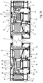
- in a) eine Ansicht eines Schwing-/Wendefensters und in b) bis e) Schnitte senkrecht zur Zeichenebene aus a) längs der Geraden A-A, B-B. C-C und D-D aus a).
- Fig. 2
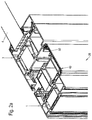
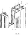
- in a) bis c) perspektivische Ansichten eines bzw. nahe zu einem Stoßbereich eines Wechselprofils des Schwing-//Wendefensters aus
Fig. 1 ); und zwar in a) mit Sicht auf die Anordnung eines Wechselprofils am Blendrahmen und in b) teilgeschnitten mit Sicht auf die Anordnung des Wechselprofils am Flügelrahmen und in c) abschnittsweise am Blendrahmen und abschnittsweise am Flügelrahmen; und - Fig. 3
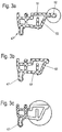
- in a) bis c) Varianten eines Mitteldichtungsprofils für ein Schwing/Wendefenster, insbesondere nach Art der
Fig. 1 . - Das in
Fig. 1 dargestellte Schwing-/Wendefenster weist einen umlaufend geschlossenen Blendrahmen 1 auf und einen Flügel 2 mit einem umlaufenden geschlossenen Flügelrahmen 3, der ein Flächenelement, insbesondere eine Isolierglasscheibe 4, einfasst. Im geschlossenen Zustand des Flügels 2 definiert die Isolierglasscheibe 4 eine Ebene E, die nachfolgend auch vereinfacht als Fensterebene bezeichnet wird. - Der Blendrahmen 1 und der Flügelrahmen 3 sind jeweils als Rechteckrahmen aus Profilholmen 5, 6, 7 und 8 bzw. 9, 10, 11 und 12 gebildet, die in Eckbereichen miteinander verbunden sind (z.B. in Stoßbereichen mit hier nicht dargestellten Eckverbindern) wobei jeweils zwei der Profilholme 5, 7 bzw. 9, 11 vorzugsweise vertikal und zwei der Profilholme 6, 8 bzw. 10, 12 horizontal und jeweils parallel zueinander ausgerichtet sind.
- Der Flügel 2 bzw. der Flügelrahmen 3 ist schwenkbar gelenkig am Blendrahmen 1 angeordnet. Die Drehachse X, um welche der Flügel 2 verschwenkt werden kann, liegt dabei genau oder nahe zu der der Mitte der sich vertikal erstreckenden Profilholme 5, 7 bzw. 9, 11. Die Drehachse X, um welche der Flügel 2 verschwenkt werden kann, kann alternativ auch in der Mitte oder nahe zu der Mitte der sich horizontal erstreckenden Profilholme liegen (hier nicht dargestellt, alle nachfolgenden Ausführen beziehen sich insofern analog auch auf ein derartiges Fenster, das im Grunde einfach durch Kippen der Anordnung aus
Fig. 1 am Einbauort um 90° nach links oder rechts gebildet werden kann). Zwischen dem Blendrahmen 1 und dem Flügel 2 ist ein umlaufender Falzraum 13 ausgebildet (sieheFig. 1b und1c ). - Zur Öffnen und Schliessen dient vorzugsweise ein Handgriff 14 (
Fig. 1 ), mit dem eines oder mehrere Verriegelungselemente (hier nicht dargestellt) zwischen dem Flügel 2 und dem Blendrahmen 1 lösbar sind, um den Flügel 2 zu entriegeln. Mit dem Handgriff 14 kann der Flügel 2 sodann um die Drehachse X verschwenkt werden. - Durch die mittige Anordnung der Drehachse X wird der Flügel 2 beim Öffnen teilweise nach innen (vorzugsweise in seinem Bereich oberhalb der Drehachse) und teilweise nach außen (vorzugsweise in seinem Bereich unterhalb der Drehachse) bewegt und nicht als Ganzes nach außen oder innen, wie dies beispielsweise bei einem Dreh-/Kippfenster der Fall ist. Das Fenster wird aufgrund dieser Eigenschaften als Schwing-/Wendefenster bezeichnet. Rein beispielhaft sei in Hinsicht auf die mögliche Ausgestaltung eines Schwing- Wendefensters sowie eines einsetzbaren Beschlages für ein Schwing-/Wendefenster auf die
DE 37 19 169 A1 verwiesen. - Ein besonderes Problem bei der Ausgestaltung eines Schwing-/Wendefensters besteht darin, den Falzraum 13 (siehe
Fig. 1 b) und1c) ) zwischen dem Blendrahmen 1 und dem Flügelrahmen 2 mit möglichst einfachen konstruktiven Mitteln genügend dicht auszugestalten, so dass er im geschlossenen Zustand des Flügels 2 Schlagregen standhält und keinen oder nur einen vernachlässigbaren Luftdurchzug zulässt. Dies gilt insbesondere vor dem Hintergrund, dass gewünscht ist, dass an einer oder mehreren Stellen im Falzraum 13 eine senkrecht zur Flügelebene (Zeichenebene derFig. 1 a) wirkende Kraft auf den oder die Dichtbereiche im geschlossenen Zustand des Flügels 2 einwirken können soll. - Die Erfindung erfüllt diese Funktionalität in einer besonders einfachen Weise. Um dies zu verstehen, sei zunächst der Aufbau der Blend- und des Flügelrahmens 1, 3 näher erläutert.
- Sowohl der Blendrahmen 1 als auch der Flügelrahmen 3 (siehe
Fig. 1 b) und1c) weisen hier jeweils ein Basisprofil 15, 16 auf. Diese umlaufend vorgesehenen Basisprofile 15, 16 sind vorzugsweise jeweils als Verbundprofile ausgebildet oder bestehen aus nur einem Werkstoff. Diese Verbundprofile weisen vorzugsweise zwei oder mehr Einzelprofile auf. Vorzugsweise weisen sie jeweils vorzugweise Innen- und Außenmetallprofile 17, 18 bzw. 19, 20 auf, die über wenigstens eine Isolierstegebene aus einem oder mehreren Isolierprofilen 21, 22 bzw. 23, 24 miteinander verbunden sind. Die Innen- und Außenmetallprofile 17, 18 bzw. 19, 20 können jeweils mit wenigstens einer oder mehreren Hohlkammern versehen sein. Das Basisprofil 15 des Flügelrahmens 3 wird vorzugsweise durch eine (hier nicht weiter zu beschreibende) Glashalteleiste und Dichtungen an der Isolierglasscheibe vervollständigt. - Dabei ist auf den voneinander abgewandten Seiten der horizontalen Drehachse X - also hier oberhalb und unterhalb der Drehachse X - (bzw. bei einer vertikalen Drehachse links und rechts der Drehachse X) jeweils ein weiteres Profil - das Wechselprofil 25 genannt wird - einmal an dem Blendrahmen 1 und einmal an dem Flügelrahmen 2 bzw. an dessen Basisprofil(en) 15 bzw. 16 befestigt. Dies erschließt sich besonders gut aus dem Zusammenspiel der
Figuren 1 b) und1 c) , die Schnitte durch horizontal verlaufene Ebenen längs der Linien A-A und B-B einmal oberhalb und einmal unterhalb der Drehachse X zeigen. DieFiguren 1d ) und1e ), die Schnitte durch vertikale Ebenen (längs der Linien C-C und D-D zeigen, sind gleich, da oberhalb und unterhalb der Drehachse X jeweils der Aufbau "einheitlich" ist, da hier - wie noch im Detail zu erörtern - das Wechselprofil 25 jeweils in dem ganzen Bereich am Flügelrahmen (oberhalb der Drehachse X) oder am Blendrahmen 1 (unterhalb der Drehachse) befestigt ist. - Das Wechselprofil 25 ist vorzugsweise ebenfalls als vorteilhaft als (gut) thermisch isolierendes Verbundprofil ausgebildet. Dieses Verbundprofil weist hier in vorteilhafter Ausgestaltung ein Metallprofil 26 (zur Rauminnenseite hin) auf und ein daran nach außen hin angesetztes Kunststoffprofil 27. Das Metallprofil 26 und/oder das Kunststoffprofil 27 sind hier in bevorzugten - aber nicht zwingender - Ausgestaltung jeweils mit einer oder mehreren Hohlkammern 29, 30 versehen. Das Kunststoffprofil 27 wirkt dabei (auch) als ein Isolierprofil. Der Querschnitt des Wechselprofils 25 wird von innen (in
Fig. 1b unten) nach außen (inFig. 1b oben) hier in mehreren Stufen abschnittsweise schmaler. Es reicht nicht bis an die Außenseite heran sondern endet vorteilhaft unterhalb der Außenebene der Basisprofile 15, 16. Dies vereinfacht die Abdichtung der Konstruktion und verbessert die Außenansicht. Insbesondere auch das Metallprofil 26 kann umlaufend eingesetzt werden. - Aus dem Zusammenspiel der
Fig. 1 a) bis e) erschließt sich, dass das Wechselprofil 25 bei dem Schwing-/Wendefenster nachFig. 1a ) oberhalb der Drehachse (bzw. oberhalb der durch die Drehachse X sich senkrecht zur Flügelebene erstreckenden Ebene) an dem Basisprofil 16 des Flügelrahmens 3 befestigt ist und unterhalb der Drehachse X an dem Basisprofil 15 des Blendrahmens 1. Die Befestigung erfolgt jeweils mit dazu geeigneten Befestigungsmitteln, hier mit Schrauben 30, die sich vorzugsweise parallel zur Flügelebene erstrecken und die vorzugsweise in die Hohlkammern des Wechselprofils 25 und - je nach Ort oberhalb oder unterhalb der Drehachse X - des Basisprofils des Flügel- bzw. Blendrahmens 3, 1 eingreifen. - Dabei sind hier in vorteilhafter Weise drei Dichtungsanordnungen mit drei räumlich voneinander beabstandeten Dicht-Anlagebereichen I, II, III bzw. I', II', III' im Falzraum 13 ausgebildet, und zwar oberhalb der Drehachse zwischen dem Wechselprofil 25 und dem Blendrahmen 1 und unterhalb der Drehachse zwischen dem Wechselprofil 25 und dem Flügelrahmen 3.
- Eine erste dieser Dichtungsanordnungen - eine Außendichtungsanordnung I zur Außenseite des Fensters hin - ist an dem im geschlossenen Zustand äußeren Bereich zwischen dem Wechselprofil 25 und dem Flügelrahmen 3 (oberhalb der Drehachse X) bzw. an dem im geschlossenen Zustand äußeren Bereich zwischen dem Wechselprofil 25 und dem Blendrahmen 1 (unterhalb der Drehachse X) ausgebildet.
- Hierzu sind umlaufend am Rahmen Nuten 31, 32 jeweils an Stegen 33, 34 des Blend- bzw. Flügelrahmens 1, 3 ausgebildet, in welche oberhalb der Drehachse X am Blendrahmen 3 und unterhalb der Drehachse X am Flügelrahmen jeweils ein Dichtungsprofil 35, 36 eingesetzt ist, das den Spalt bzw. Falzraum 13 zwischen dem Blendrahmen 1 (oberhalb der Drehachse X) und dem Wechselprofil 25 bzw. zwischen dem Flügelrahmen 3 und dem Wechselprofil 25 (unterhalb der Drehachse X) jeweils abdichtet. An dem Kunststoffprofil 27 des Wechselprofils 25 ist zur Außenseite hin zudem ein flexibler Steg 37 ausgebildet, welcher einen Fußbereich 38 aufweist, der auf den beiden Seiten der Drehachse X vorzugsweise rastend jeweils in die andere Nut an dem Steg desjenigen Basisprofils am Blend- oder Flügelrahmen 1, 3 eingreift, an welchem das Wechselprofil 25 jeweils befestigt ist. Derart wird eine sichere und optisch ansprechend gestaltete Anlage des Wechselprofils 25 in diesem Bereich an dem Profil (des Flügelrahmens oder des Blendrahmens) geschaffen, an dem es jeweils festgelegt ist.
- Dabei wirkt eine Kraft senkrecht zur Fensterebene E im ersten Dichtbereich I im Fensterspalt, so dass dieser erste Dichtbereich als ein Dichtbereich mit der Fähigkeit zur Dichtung unter der Einwirkung von dynamischen, d.h. wechselnden auf ihn wirkenden Kräften anzusehen ist (verursacht durch Wind und dgl.).
- Zur Ausbildung einer zweiten der Dichtungsanordnungen mit einem zweiten der Dicht-Anlagebereiche II, II' (Innendichtungsanordnung) kann wiederum vorteilhaft das Wechselprofil 25 genutzt werden. Hierzu sind vorzugsweise zwei Nuten 39, 40 an voneinander weg weisenden sowie parallel zur Fensterebene an der Innenseite I des Wechselprofils ausgebildeten Stegen 41, 42 des Wechselprofils ausgebildet. In jede dieser Nuten ist jeweils ein Dichtungsprofil 43, 44 eingesetzt. Oberhalb der Drehachse dient das eine der Dichtungsprofile 43 als Anlagedichtung zur Dichtung unter einer Einwirkung dynamisch veränderlicher Kräfte zwischen dem Wechselprofil 25 und dem Blendrahmenprofil 1 im Falzraum 13 (oberhalb der Drehachse X) und das andere dieser beiden Dichtungsprofile 44 dient als Dichtung (nicht im Falztraum 13 sondern innerhalb des Flügelrahmens) unter Einwirkung einer statischen konstanten Kraft und als Sichtschutz zur Abdeckung des Spaltes zwischen dem Wechselprofil 25 und dem Basisprofil 15 des Flügelrahmenprofils 3, mit dem es verschraubt ist. Unterhalb der Drehachse dient das andere der Dichtungsprofile 44 als Anlagedichtung zur Abdichtung auch unter der Einwirkung dynamischer Kräfte zwischen dem Wechselprofil 25 und dem Flügelrahmenprofil 3 im Falzraum 13 und das andere dieser beiden Dichtungsprofile 43 dient als statische Dichtung und als Sichtschutz zur Abdeckung eines Spaltes zwischen dem Wechselprofil 25 und dem Blendrahmenprofil1, mit dem es auf dieser Seite der Drehachse X verschraubt ist (
Fig. 1b undc ). - Auch in dem Dicht-Anlagebereich II wirken sich verändernde Kräfte FII senkrecht zur Fensterebene E im Dicht-Anlagebereich II im Fensterspalt. Daher ist auch dieser Dicht-Anlagebereich abschnittsweise als ein Dichtbereich zur Dichtung auch unter der Einwirkung dynamischer bzw. wechselnder Kräfte anzusehen (verursacht durch Wind und dgl.) und abschnittsweise als statische Dichtung zur Abdichtung eins starren, sich nicht veränderten Spaltes zwischen dem Wechselprofil 25 und jeweils dem Rahmen bzw. den Profilen (Flügelrahmen 3 oder Blendrahmen 1), mit dem das Wechselprofil verschraubt ist.
- Vorzugsweise ergänzend zu dem ersten und dem zweiten Dicht-Anlagebereich I, II gibt es einen (weiteren) Dicht-Anlagebereich III, III' der zwischen "Außen" und "Innen" und dort zwischen dem ersten und dem zweiten Dicht-Anlagebereich I, II (bzw. I', II') ausgebildet ist, und zwar vorzugweise umlaufend im Fensterspalt, allerdings oberhalb und unterhalb der Drehachse X jeweils zwischen verschiedenen Elementen des Schwing-/Wendefensters.
- Auch bzw. insbesondere der dritte Dichtbereich III, III' zeichnet sich sowohl durch einen statischen Dichtbereichsabschnitt mit der Eignung zur Dichtung unter dem Einfluss einer konstant wirkenden Kraft im Dichtbereichsabschnitt und einen dynamischen Dichtbereichsabschnitt unter dem Einfluss wechselnder Kräften aus, die auf diesen Dichtbereichsabschnitt wirken. Dies sei nachfolgend beispielhaft näher erläutert.
- Das Wechselprofil 25, insbesondere dessen Kunststoffprofil 27 weist zwischen den Dicht-Anlagebereichen I und II zwei Anlagebereiche 45, 46 für Mitteldichtungsprofile 47, 48 des Flügel- und des Blendrahmens 3, 1 auf (
Fig. 1 b) . Diese Mitteldichtungsprofile 47, 48 des Flügelrahmens 3 einerseits und des Blendrahmens 1 andererseits erstrecken sich jeweils im Falzraum 13 im Wesentlichen parallel zur Fensterebene E. Die Dichtungsprofile 47, 48 können im Endbereich als Schlauchdichtungen ausgebildet sein (was für eine gute Wärmedämm- und Dichtwirkung sorgt) und/oder eine oder mehrere Hohlkammern (was die Wärmedämmung optimiert) aufweisen und bestehen vorzugsweise aus einem elastischen Dichtmaterial. Dabei überlappen sich die Mitteldichtungsprofile 47, 48 des Blendrahmens 1 und des Flügelrahmens 3 jeweils mit dem Wechselprofil 25, insbesondere mit dessen Kunststoffprofil 27, in einer Richtung parallel zur Fensterebene. Sie liegen in diesen Bereichen ferner dichtend an dem Wechselprofil 25 an. Die Mitteldichtungsprofile sind vorzugsweise jeweils mit einem Fuß versehen, der jeweils in einer korrespondierenden Nut in einem Basisprofile 15, 16 des Blend- bzw. Flügelrahmens festgelegt ist - Oberhalb und unterhalb der Drehachse X liegt der Anlagebereich 45 einmal im Falzraum 13 zwischen dem Wechselprofil 25 und dem Mitteldichtungsprofil 47 des Blendrahmens 1 und unterhalb des Drehachse liegt der Anlagebereich 46 im Falzraum 13 zwischen dem Wechselprofil 25 und dem Mitteldichtungsprofil 48 des Flügelrahmens 3, wobei eine dynamisch sich mit den wirkenden Einflüssen (Wind und dgl., Schließkraft) verändernde Kraft senkrecht zur Fensterebene in den jeweiligen Anlagebereichen im Falzraum 13 wirkt bzw. wirken kann. Derart wird jeweils ein Dichtbereichsabschnitt zur Dichtung unter Einwirkung dynamisch veränderlicher Kräfte im Falzraum 13 gebildet.
- Der jeweils andere Anlagebereich 46 (oberhalb der Drehachse X zwischen dem Mitteldichtungsprofil 48 des Flügelrahmens und dem Wechselprofil 25 und der Anlagebereich 45 unterhalb der Drehachse X zwischen dem Mitteldichtungsprofil 47 des Blendrahmens 1 und dem Wechselprofil 25 ist dann jeweils ein Anlagebereich bzw. ein Dichtbereichsabschnitt mit einer Dichtwirkung nur unter Einwirkung rein statisch kontanter Kraft, der nicht zur Dichtwirkung im Falzbereich 13 beiträgt.
- Besonders vorteilhaft an dieser zunächst überraschend erscheinenden Ausgestaltung mit einem "dynamischen" und einem "statischen" Mitteldichtungsbereich ist, dass die Mitteldichtungsprofile zwischen dem Blendrahmen 1 und dem Flügelrahmen 3 umlaufend gleich gestaltet werden bzw. sein können und auch umlaufend angeordnet werden können. Es muss lediglich das Wechselprofil 25 unterhalb und oberhalb der Drehachse X einmal am Flügelrahmen 3 und einmal am Blendrahmen 1 montiert werden. Dennoch stellt sich ohne weiteres eine dynamische Dichtwirkung mit einer Anlagekraft senkrecht zur Fensterebene E im Falzraum 13 ein.
- Das Wechselprofil 25 wird - wie bereits erläutert nach
Fig. 1 oberhalb und unterhalb der Drehachse X einmal an dem Flügelrahmen 2 (senkrecht zur Drehachse oberhalb der Drehachse) und einmal an dem Blendrahmen 1 (unterhalb der Drehachse X) befestigt. Damit entsteht ein Stoßbereich 49 zwischen den jeweiligen Wechselprofilen in der Höhe bzw. im Bereich der Drehachse D. Zwar liegen die Konturen der Wechselprofile 25 oberhalb und unterhalb des Stoßbereiches 49 direkt aneinander. Es ist aber dennoch vorteilhaft, den Stoßbereich 39 separat ergänzend abzudichten, beispielsweise indem er mit einem Dichtband 50 überdeckt wird, und zwar zumindest zur Innenseite hin (d.h. zur Raumseite R hin). Dieses Dichtband wird vorzugsweise an einem der beiden Wechselprofile insbesondere unlösbar befestigt, so dass es mit seiner halben Breite über den Stoßbereich vorsteht, den es dann im geschlossenen Zustand überdeckt. Denkbar ist es, auch an der Außenseite ein solches Dichtband 50 vorzusehen (hier nicht dargestellt). - Insgesamt wird derart ein Schwing-/Wendefenster geschaffen, dass einen bestechend einfachen und übersichtlichen konstruktiven Aufbau aufweist, das entsprechend leicht montierbar ist und das auf einfache Weise die Möglichkeit dazu bildet, Dicht-Anlagebereiche mit dynamischen Dichtbereichsabschnitten im Falzraum 13 und zudem statische Dichtbereichsabschnitten zwischen dem Wechselprofil 25 und jeweils dem Profil, an dem es befestigt ist, auszubilden.
- Anzumerken ist nochmals, dass Begriffe wie "oberhalb" und "unterhalb" in der Beschreibung bei einem Schwing-/Wendefenster mit einer vertikalen Drehachse entsprechend durch "links" und rechts" ersetzbar sind bzw. zu ersetzen sind.
- Die Mitteldichtungsprofile 47, 48 können vollständig identisch aufgebaut sein. Es ist aber auch denkbar, sie nur abschnittsweise identisch auszubinden und an ihnen einen oder mehrere lösbare Bereiche 51, 52 vorzusehen. Vorzugsweise weist einer dieser Bereiche eine Hohlkammer 53 auf.
- Der eine oder die mehreren lösbaren Bereiche 51, 52 können eine oder mehrere verschiedene Funktionen erfüllen. So kann einer der Bereiche 51 dazu dienen, den Falzraum 13 bzw. Spalt zu verkleinern, um die Konvektion zwischen innen und außen weiter zu verringern. Dieser lösbare Bereich 51 (siehe
Fig. 3a, b, c ) wird dann jeweils an dem Rahmen (Blend- oder Flügelrahmen 1, 3) abgetrennt, an dem das Wechselprofil 25 befestigt ist. Dies bedeutet, dass der lösbare Bereich bei dem inFig. 1 dargestellten Fenster oberhalb der Drehachse an dem Flügelrahmen 3 entfernt wird (Fig. 3c ), während er dort an dem Blendrahmen 1 stehen gelassen wird (Fig. 3b ). Unterhalb der Drehachse ist diese Anordnung umgekehrt. Realisiert werden kann der lösbare Bereich durch Einschnitte in den Mitteldichtungsprofilen. Derart ist es auch denkbar, mit nur einer Art von Dichtungsprofil 47, 48 mehrere Einsatzmöglichkeiten zu bedienen oder unterschiedliche Bautiefen. -
- Blendrahmen
- 1
- Flügel
- 2
- Flügelrahmen
- 3
- Isolierglasscheibe
- 4
- Profilholme
- 5 - 12
- Falzraum
- 13
- Handgriff
- 14
- Basisprofil
- 15, 16
- Innen- und Außenmetallprofile
- 17, 18 bzw. 19, 20
- Isolierprofile
- 21, 22 bzw. 23, 24
- Wechselprofil
- 25
- Metallprofil
- 26
- Kunststoffprofil
- 27
- Hohlkammern
- 28, 29
- Schrauben
- 30
- Nuten
- 31, 32
- Steg
- 33, 34
- Dichtungsprofil
- 35, 36
- Steg
- 37
- Fußbereich
- 38
- Nuten
- 39, 40
- Stege
- 41, 42
- Dichtungsprofil
- 43, 44
- Anlagebereiche
- 45, 46
- Mitteldichtungsprofile
- 47, 48
- Stoßbereich
- 49
- Dichtband
- 50
- lösbare Bereiche
- 51, 52
- Hohlkammer
- 53
- Drehachse
- D
- Dichtbereiche
- I, II, III; I', II', III'
Claims (16)
- Schwing-/Wendefenster, das folgendes aufweist:a. einen vorzugsweise umlaufend geschlossenen Blendrahmen (1),b. einen Flügel (2) mit einem vorzugsweise umlaufenden geschlossenen Flügelrahmen (3), der ein Flächenelement, insbesondere eine Isolierglasscheibe (4), aufnimmt,c. wobei der Flügel (2) mit dem Flügelrahmen (3) im Bereich eines Drehgelenks mit einer Drehachse (X) schwenkbar am Blendrahmen (1) gelagert ist, derart, dass der Flügel (2) beim Öffnen zunächst teilweise nach innen und teilweise nach außen bewegbar ist,d. wobei sowohl der Blendrahmen (1) als auch der Flügelrahmen (3) jeweils ein Basisprofil (15, 16) aufweisen, an denen abwechselnd zu den beiden Seiten der Drehachse X hin ein Wechselprofil (25) befestigt ist, so dass ein Falzraum (13) zwischen dem Blend- und dem Flügelrahmen (1, 3) abschnittsweise zwischen dem Basisprofil des Blendrahmens (1) und dem Wechselprofil (25) und zwischen dem Basisprofil des Flügelahmens (3) und dem Wechselrahmen (25) ausgebildet ist, dadurch gekennzeichnet, dasse. wenigstens eine Dichtungsanordnung oder mehrere Dichtungsanordnungen vorgesehen ist/sind, die jeweils einen Dicht-Anlagebereich (III, III') ausbildet/ausbilden, deri. einen ersten Dichtungsbereichsabschnitt aufweist, der zwischen dem Wechselprofil (25) und dem Basisprofil des Blendrahmens (1) ausgebildet ist undii. einen zweiten Dichtungsbereichsabschnitt, der zwischen dem Wechselprofil (25) und dem Basisprofil des Flügelrahmens (2) ausgebildet ist.
- Schwing-/Wendefenster nach Anspruch 1, dadurch gekennzeichnet, dass der erste Dichtungsbereichsabschnitt auf der einen Seite der Drehachse zur Dichtung unter der Einwirkung statisch konstanter Kräfte dient und auf der anderen Seite der Drehachse als Dichtung unter der Einwirkung dynamisch veränderlicher Kräfte.
- Schwing-/Wendefenster nach Anspruch 1 oder 2, dadurch gekennzeichnet, dass der zweite Dichtungsbereichsabschnitt in dem Bereich, in dem der erste Dichtungsbereichsabschnitt zur Dichtung unter Einwirkung einer konstanten Kraft wirkt, zur Dichtung unter einer Einwirkung dynamisch veränderlicher Kräfte ausgelegt ist und dass der der zweite Dichtungsbereichsabschnitt in dem Bereich, in dem der erste Dichtungsbereichsabschnitt zur Dichtung unter der Einwirkung dynamisch veränderlicher Kräfte dient, zur Dichtung unter der Einwirkung statisch konstanter Kräfte ausgelegt ist.
- Schwing-/Wendefenster nach einem der vorstehenden Ansprüche, dadurch gekennzeichnet, dass das Wechselprofil (25) als ein Verbundprofil ausgebildet ist, dass wenigstens ein Metallprofil (26) aufweist und ein daran angesetztes Kunststoffprofil (27).
- Schwing-/Wendefenster nach einem der vorstehenden Ansprüche, dadurch gekennzeichnet, dass das Wechselprofil (25) bei einem Schwing- /Wendefenster mit horizontaler Drehachse oberhalb dieser an dem Basisprofil (16) des Flügelrahmens (3) befestigt ist und unterhalb der Drehachse X an dem Basisprofil (15) des Blendrahmens (1).
- Schwing-/Wendefenster nach einem der vorstehenden Ansprüche, dadurch gekennzeichnet, dass drei der Dichtungsanordnungen mit drei räumlich voneinander beabstandeten Dicht-Anlagebereichen (I, II, III bzw. II', III') im Falzraum (13) beidseits der Drehachse X ausgebildet sind.
- Schwing-/Wendefenster nach einem der vorstehenden Ansprüche, dadurch gekennzeichnet, dassa. eine der Dichtungsanordnungen als Außendichtungsanordnung (I) an dem im geschlossenen Zustand äußeren Bereich zwischen dem Wechselprofil (25) und dem Flügelrahmen (3) (auf der einen Seite der Drehachse X) bzw. an dem im geschlossenen Zustand äußeren Bereich zwischen dem Wechselprofil (25) und dem Blendrahmen (1) (auf der anderen Seite der Drehachse X) ausgebildet ist, und/oderb. eine der Dichtungsanordnungen als Innendichtungsanordnung an dem im geschlossenen Zustand inneren Bereich zwischen dem Wechselprofil (25) und dem Flügelrahmen (3) (auf der einen Seite der Drehachse X) bzw. an dem im geschlossenen Zustand äußeren Bereich zwischen dem Wechselprofil (25) und dem Blendrahmen (1) (auf der anderen Seite der Drehachse X) ausgebildet ist.
- Schwing-/Wendefenster nach einem der vorstehenden Ansprüche, dadurch gekennzeichnet, dass zur Ausbildung der Innendichtungsanordnung zwei Nuten (39, 40) an Stegen (41, 42) des Wechselprofils ausgebildet sind, wobei in jede dieser Nuten (39, 40) jeweils ein Dichtungsprofil (43, 44) eingesetzt ist, wobei das eine der Dichtungsprofile (43) auf der einen Seite der Drehachse als dynamische Dichtung zwischen dem Wechselprofil (25) und dem Basisprofils (15) des Blendrahmenprofils (1) im Falzraum (13) dient und das andere dieser beiden Dichtungsprofile (44) auf dieser Seite der Drehachse (X) als Sichtschutz zur Abdeckung des Spaltes zwischen dem Wechselprofil (25) und dem Basisprofil (15) des Flügelrahmenprofils (3) an dem es befestigt ist und wobei diese Funktionalität auf der anderen Seite der Drehachse umgedreht ist.
- Schwing-/Wendefenster nach einem der vorstehenden Ansprüche, dadurch gekennzeichnet, dass zur Ausbildung von einem der Dicht-Anlagebereiche (III, III') das Wechselprofil (25), insbesondere dessen Kunststoffprofil (27), zwei Anlagebereiche (45, 46) für Mitteldichtungsprofile (47, 48) des Flügel- und des Blendrahmens (3, 1) aufweist, wobei die Mitteldichtungsprofile (47, 48) vorzugsweise eine oder mehrere Hohlkammern aufweisen und/oder im Anlagebereich als Schlauchdichtungen ausgebildet sind.
- Schwing-/Wendefenster nach einem der vorstehenden Ansprüche, dadurch gekennzeichnet, dass sich die Mitteldichtungsprofile (47, 48) jeweils mit dem Wechselprofil (25), insbesondere mit dessen Kunststoffprofil 27, in einer Richtung parallel zur Fensterebene (E) überlappen und dass sie in diesen Bereichen ferner dichtend an dem Wechselprofil (25) in den Anlagebereichen (45, 46) anliegen.
- Schwing-/Wendefenster nach einem der vorstehenden Ansprüche, dadurch gekennzeichnet, dassa. auf der einen Seite der Drehachse (X) der eine Anlagebereich (45) einmal im Falzraum (13) zwischen dem Wechselprofil (25) und dem Mitteldichtungsprofil (47) des Blendrahmens (1) liegt und dass auf der anderen Seite der Drehachse der andere Anlagebereich (46) im Falzraum (13) zwischen dem Wechselprofil (25) und dem Mitteldichtungsprofil (48) des Flügelrahmens (3) liegt, so dass jeweils der Dichtbereichsabschnitt zur Dichtung unter Einwirkung dynamisch veränderlicher Kräfte im Falzraum (13) gebildet ist, und/oderb. dass der jeweils andere Anlagebereich (46) auf der anderen Seite der Drehachse (X) zwischen dem Mitteldichtungsprofil (48) des Flügelrahmens (3) und dem Wechselprofil (25) und der Anlagebereich (45) auf der einen Seite der Drehachse X zwischen dem Mitteldichtungsprofil (47) des Blendrahmens (1) und dem Wechselprofil (25) liegt und als Dichtbereichsabschnitt mit einer Dichtwirkung nur unter Einwirkung rein statisch kontanter Kraft ausgelegt ist.
- Schwing-/Wendefenster nach einem oder mehreren der vorstehenden Ansprüche, dadurch gekennzeichnet, dass zumindest in einem Stoßbereich (49) zwischen im Bereich der Drehachse (X) aneinander stoßenden Wechselprofilen (25) wenigstens eine Dichtung, insbesondere ein Dichtband (50) vorgesehen ist.
- Schwing-/Wendefenster nach einem der vorstehenden Ansprüche, dadurch gekennzeichnet, dass die Mitteldichtungsprofile (47, 48) ganz oder abschnittsweise identisch ausgebildet sind und/oder dass die Mitteldichtungsprofile (47, 48) einen oder mehrere Abtrennbereiche (51, 52) aufweisen.
- Schwing-/Wendefenster nach einem der vorstehenden Ansprüche, dadurch gekennzeichnet, dass der erste Dichtungsbereichsabschnitt umlaufend zwischen dem Wechselprofil (25) und dem Basisprofil des Blendrahmens (1) ausgebildet ist und/oder dass der zweite Dichtungsbereichsabschnitt umlaufend zwischen dem Wechselprofil (25) und dem Basisprofil des Flügelrahmens (2) ausgebildet ist.
- Schwing-/Wendefenster nach einem der vorstehenden Ansprüche, dadurch gekennzeichnet, dass der erste Dichtungsbereichsabschnitt auf einer Seite der Drehachse (X) U-förmig abschnittsweise umlaufend zwischen dem Wechselprofil (25) und dem Basisprofil des Blendrahmens (1) ausgebildet ist und/oder dass der zweite Dichtungsbereichsabschnitt auf der anderen Seite der Drehachse (X) U-förmig abschnittsweise umlaufend zwischen dem Wechselprofil (25) und dem Basisprofil des Flügelrahmens (2) ausgebildet ist.
- Schwing-/Wendefenster nach einem der vorstehenden Ansprüche, dadurch gekennzeichnet, dass das Wechselprofil (25) von einer Seite aus, insbesondere von einer Gebäudeaußenseite aus, nicht sichtbar ist und/oder dass das Wechselprofil (25) umlaufend am Rahmen den gleichen Aufbau hat, aber beidseits der Drehachse (X) verschieden angeordnet ist.
Applications Claiming Priority (1)
| Application Number | Priority Date | Filing Date | Title |
|---|---|---|---|
| DE102015100543.3A DE102015100543A1 (de) | 2015-01-15 | 2015-01-15 | Schwing-Wendefenster mit einer Dichtungsanordnung |
Publications (2)
| Publication Number | Publication Date |
|---|---|
| EP3045648A1 true EP3045648A1 (de) | 2016-07-20 |
| EP3045648B1 EP3045648B1 (de) | 2021-05-05 |
Family
ID=54936940
Family Applications (1)
| Application Number | Title | Priority Date | Filing Date |
|---|---|---|---|
| EP15202303.2A Active EP3045648B1 (de) | 2015-01-15 | 2015-12-23 | Schwing-wendefenster mit einer dichtungsanordnung |
Country Status (2)
| Country | Link |
|---|---|
| EP (1) | EP3045648B1 (de) |
| DE (1) | DE102015100543A1 (de) |
Citations (2)
| Publication number | Priority date | Publication date | Assignee | Title |
|---|---|---|---|---|
| DE3719169A1 (de) | 1986-06-12 | 1987-12-17 | Parys Remi E Van | Beschlag fuer ein horizontal schwenkbares oder ein vertikal schwenkbares fenster |
| DE4204363A1 (de) * | 1992-02-14 | 1993-08-19 | Bernhard Kreye | Entwaesserung von aus hohlprofilen gebogenen rahmen eines runden oder ovalen schwingfluegelfensters |
Family Cites Families (7)
| Publication number | Priority date | Publication date | Assignee | Title |
|---|---|---|---|---|
| DE7518339U (de) * | 1975-10-09 | Wieland Werke Ag | Schwing- und Wendeflügelfenster | |
| DE1831385U (de) * | 1961-01-10 | 1961-05-18 | Ver Deutsche Metallwerke Ag | Elastischer dichtungsstreifen fuer fluegeltueren und drehfenster, insbesondere fuer aus metall bestehende ueberschlagtueren bzw. schwingfluegelfensterrahmen. |
| DE1943107U (de) * | 1966-05-14 | 1966-07-28 | Wieland Werke Ag | Schwing- und wendefluegelfenster. |
| DE1985409U (de) * | 1968-02-17 | 1968-05-16 | Broekelmann Aluminium F W | Schwing- oder wendefluegelfenster. |
| DE2550132A1 (de) * | 1975-11-07 | 1977-05-12 | Albrecht Gmbh Stahl Und Metall | Schwing- oder wendefenster |
| DE7802874U1 (de) * | 1978-02-01 | 1978-05-11 | Wieland-Werke Ag, 7900 Ulm | Waermegedaemmtes schwing- oder wendefluegelfenster |
| DE19857650A1 (de) * | 1997-12-18 | 1999-06-24 | Hautau Gmbh W | Außenliegendes Lager für einen Schwingflügel |
-
2015
- 2015-01-15 DE DE102015100543.3A patent/DE102015100543A1/de not_active Withdrawn
- 2015-12-23 EP EP15202303.2A patent/EP3045648B1/de active Active
Patent Citations (2)
| Publication number | Priority date | Publication date | Assignee | Title |
|---|---|---|---|---|
| DE3719169A1 (de) | 1986-06-12 | 1987-12-17 | Parys Remi E Van | Beschlag fuer ein horizontal schwenkbares oder ein vertikal schwenkbares fenster |
| DE4204363A1 (de) * | 1992-02-14 | 1993-08-19 | Bernhard Kreye | Entwaesserung von aus hohlprofilen gebogenen rahmen eines runden oder ovalen schwingfluegelfensters |
Also Published As
| Publication number | Publication date |
|---|---|
| DE102015100543A1 (de) | 2016-07-21 |
| EP3045648B1 (de) | 2021-05-05 |
Similar Documents
| Publication | Publication Date | Title |
|---|---|---|
| EP3339552B1 (de) | Faltanlage mit stellleiste | |
| EP4080008B1 (de) | Tür, fenster oder fassadenelement sowie beschlaganordnung für ein solches element | |
| DE102012111005A1 (de) | Tür, insbesondere Aluminium-Haustür, und Türprofilsystem | |
| EP2472045B1 (de) | Flügel- oder Blendrahmen eines Fensters einer Tür oder dergleichen | |
| EP0843768B1 (de) | Gebäudefenster oder gebäudefenstertür | |
| DE1509553A1 (de) | Fensterkonstruktion | |
| DE2840656A1 (de) | Rahmen fuer fenster, tueren u.dgl. | |
| EP1947283B1 (de) | Fenster- oder Türflügel und Verfahren zu dessen Herstellung | |
| EP3423662B1 (de) | Blendrahmenholm und/oder flügelrahmenholm sowie tür, fenster oder fassadenelement | |
| EP3581752B1 (de) | Fenster | |
| EP3045648B1 (de) | Schwing-wendefenster mit einer dichtungsanordnung | |
| EP3680438B1 (de) | Anordnung aus einem rahmenprofil und einem dichtprofil für einen fenster- oder türrahmen | |
| EP0011124B2 (de) | Tür oder Fenster | |
| EP2072745A2 (de) | Fenster mit Blend- und Flügelrahmen | |
| DE19609624C2 (de) | Gebäudefenster und/oder Gebäudefenstertür | |
| DE20100618U1 (de) | Rahmenprofil | |
| EP3299567B1 (de) | Holmanordnung für einen gebäudeverschluss, verfahren zum herstellen einer holmanordnung sowie gebäudeverschluss | |
| DE102016125334A1 (de) | Fenster oder Tür mit einer Dichtungsanordnung und Falzdichtung | |
| DE19500226A1 (de) | Bewehrung an Türen oder Fenstern | |
| DE19814968A1 (de) | Türschwelle | |
| DE2030746A1 (de) | Fensterrahmen aus Kunststoff mit einer Verstärkungseinlage, welche zugleich Zentralverschluß ist | |
| EP3342971B1 (de) | Fenster oder tür mit einem flügelrahmen mit einem glasträger | |
| DE2550132A1 (de) | Schwing- oder wendefenster | |
| DE29713820U1 (de) | Fenster mit Blendrahmen und Flügelrahmen mit Zwangsbelüftung | |
| DE19622725C2 (de) | Gebäudefenster und/oder Gebäudefenstertür |
Legal Events
| Date | Code | Title | Description |
|---|---|---|---|
| PUAI | Public reference made under article 153(3) epc to a published international application that has entered the european phase |
Free format text: ORIGINAL CODE: 0009012 |
|
| AK | Designated contracting states |
Kind code of ref document: A1 Designated state(s): AL AT BE BG CH CY CZ DE DK EE ES FI FR GB GR HR HU IE IS IT LI LT LU LV MC MK MT NL NO PL PT RO RS SE SI SK SM TR |
|
| AX | Request for extension of the european patent |
Extension state: BA ME |
|
| STAA | Information on the status of an ep patent application or granted ep patent |
Free format text: STATUS: REQUEST FOR EXAMINATION WAS MADE |
|
| 17P | Request for examination filed |
Effective date: 20170116 |
|
| RBV | Designated contracting states (corrected) |
Designated state(s): AL AT BE BG CH CY CZ DE DK EE ES FI FR GB GR HR HU IE IS IT LI LT LU LV MC MK MT NL NO PL PT RO RS SE SI SK SM TR |
|
| STAA | Information on the status of an ep patent application or granted ep patent |
Free format text: STATUS: EXAMINATION IS IN PROGRESS |
|
| RIN1 | Information on inventor provided before grant (corrected) |
Inventor name: BEKK, NIKOLAI Inventor name: SYMENS, FAINA Inventor name: WALTHER, VANESSA Inventor name: GOEDECKER, CHRISTIAN |
|
| 17Q | First examination report despatched |
Effective date: 20190520 |
|
| RIC1 | Information provided on ipc code assigned before grant |
Ipc: E06B 3/263 20060101ALN20200218BHEP Ipc: E06B 3/40 20060101AFI20200218BHEP |
|
| GRAP | Despatch of communication of intention to grant a patent |
Free format text: ORIGINAL CODE: EPIDOSNIGR1 |
|
| STAA | Information on the status of an ep patent application or granted ep patent |
Free format text: STATUS: GRANT OF PATENT IS INTENDED |
|
| RIC1 | Information provided on ipc code assigned before grant |
Ipc: E06B 3/263 20060101ALN20201120BHEP Ipc: E06B 3/40 20060101AFI20201120BHEP |
|
| RIC1 | Information provided on ipc code assigned before grant |
Ipc: E06B 3/40 20060101AFI20201209BHEP Ipc: E06B 3/263 20060101ALN20201209BHEP |
|
| INTG | Intention to grant announced |
Effective date: 20201222 |
|
| GRAS | Grant fee paid |
Free format text: ORIGINAL CODE: EPIDOSNIGR3 |
|
| GRAA | (expected) grant |
Free format text: ORIGINAL CODE: 0009210 |
|
| STAA | Information on the status of an ep patent application or granted ep patent |
Free format text: STATUS: THE PATENT HAS BEEN GRANTED |
|
| AK | Designated contracting states |
Kind code of ref document: B1 Designated state(s): AL AT BE BG CH CY CZ DE DK EE ES FI FR GB GR HR HU IE IS IT LI LT LU LV MC MK MT NL NO PL PT RO RS SE SI SK SM TR |
|
| REG | Reference to a national code |
Ref country code: GB Ref legal event code: FG4D Free format text: NOT ENGLISH |
|
| REG | Reference to a national code |
Ref country code: CH Ref legal event code: EP |
|
| REG | Reference to a national code |
Ref country code: AT Ref legal event code: REF Ref document number: 1390012 Country of ref document: AT Kind code of ref document: T Effective date: 20210515 |
|
| REG | Reference to a national code |
Ref country code: IE Ref legal event code: FG4D Free format text: LANGUAGE OF EP DOCUMENT: GERMAN |
|
| REG | Reference to a national code |
Ref country code: DE Ref legal event code: R096 Ref document number: 502015014660 Country of ref document: DE |
|
| REG | Reference to a national code |
Ref country code: LT Ref legal event code: MG9D |
|
| PG25 | Lapsed in a contracting state [announced via postgrant information from national office to epo] |
Ref country code: LT Free format text: LAPSE BECAUSE OF FAILURE TO SUBMIT A TRANSLATION OF THE DESCRIPTION OR TO PAY THE FEE WITHIN THE PRESCRIBED TIME-LIMIT Effective date: 20210505 Ref country code: FI Free format text: LAPSE BECAUSE OF FAILURE TO SUBMIT A TRANSLATION OF THE DESCRIPTION OR TO PAY THE FEE WITHIN THE PRESCRIBED TIME-LIMIT Effective date: 20210505 Ref country code: HR Free format text: LAPSE BECAUSE OF FAILURE TO SUBMIT A TRANSLATION OF THE DESCRIPTION OR TO PAY THE FEE WITHIN THE PRESCRIBED TIME-LIMIT Effective date: 20210505 Ref country code: BG Free format text: LAPSE BECAUSE OF FAILURE TO SUBMIT A TRANSLATION OF THE DESCRIPTION OR TO PAY THE FEE WITHIN THE PRESCRIBED TIME-LIMIT Effective date: 20210805 |
|
| PG25 | Lapsed in a contracting state [announced via postgrant information from national office to epo] |
Ref country code: LV Free format text: LAPSE BECAUSE OF FAILURE TO SUBMIT A TRANSLATION OF THE DESCRIPTION OR TO PAY THE FEE WITHIN THE PRESCRIBED TIME-LIMIT Effective date: 20210505 Ref country code: GR Free format text: LAPSE BECAUSE OF FAILURE TO SUBMIT A TRANSLATION OF THE DESCRIPTION OR TO PAY THE FEE WITHIN THE PRESCRIBED TIME-LIMIT Effective date: 20210806 Ref country code: IS Free format text: LAPSE BECAUSE OF FAILURE TO SUBMIT A TRANSLATION OF THE DESCRIPTION OR TO PAY THE FEE WITHIN THE PRESCRIBED TIME-LIMIT Effective date: 20210905 Ref country code: PT Free format text: LAPSE BECAUSE OF FAILURE TO SUBMIT A TRANSLATION OF THE DESCRIPTION OR TO PAY THE FEE WITHIN THE PRESCRIBED TIME-LIMIT Effective date: 20210906 Ref country code: NO Free format text: LAPSE BECAUSE OF FAILURE TO SUBMIT A TRANSLATION OF THE DESCRIPTION OR TO PAY THE FEE WITHIN THE PRESCRIBED TIME-LIMIT Effective date: 20210805 Ref country code: PL Free format text: LAPSE BECAUSE OF FAILURE TO SUBMIT A TRANSLATION OF THE DESCRIPTION OR TO PAY THE FEE WITHIN THE PRESCRIBED TIME-LIMIT Effective date: 20210505 Ref country code: ES Free format text: LAPSE BECAUSE OF FAILURE TO SUBMIT A TRANSLATION OF THE DESCRIPTION OR TO PAY THE FEE WITHIN THE PRESCRIBED TIME-LIMIT Effective date: 20210505 Ref country code: RS Free format text: LAPSE BECAUSE OF FAILURE TO SUBMIT A TRANSLATION OF THE DESCRIPTION OR TO PAY THE FEE WITHIN THE PRESCRIBED TIME-LIMIT Effective date: 20210505 Ref country code: SE Free format text: LAPSE BECAUSE OF FAILURE TO SUBMIT A TRANSLATION OF THE DESCRIPTION OR TO PAY THE FEE WITHIN THE PRESCRIBED TIME-LIMIT Effective date: 20210505 |
|
| REG | Reference to a national code |
Ref country code: NL Ref legal event code: MP Effective date: 20210505 |
|
| PG25 | Lapsed in a contracting state [announced via postgrant information from national office to epo] |
Ref country code: NL Free format text: LAPSE BECAUSE OF FAILURE TO SUBMIT A TRANSLATION OF THE DESCRIPTION OR TO PAY THE FEE WITHIN THE PRESCRIBED TIME-LIMIT Effective date: 20210505 |
|
| PG25 | Lapsed in a contracting state [announced via postgrant information from national office to epo] |
Ref country code: RO Free format text: LAPSE BECAUSE OF FAILURE TO SUBMIT A TRANSLATION OF THE DESCRIPTION OR TO PAY THE FEE WITHIN THE PRESCRIBED TIME-LIMIT Effective date: 20210505 Ref country code: SM Free format text: LAPSE BECAUSE OF FAILURE TO SUBMIT A TRANSLATION OF THE DESCRIPTION OR TO PAY THE FEE WITHIN THE PRESCRIBED TIME-LIMIT Effective date: 20210505 Ref country code: SK Free format text: LAPSE BECAUSE OF FAILURE TO SUBMIT A TRANSLATION OF THE DESCRIPTION OR TO PAY THE FEE WITHIN THE PRESCRIBED TIME-LIMIT Effective date: 20210505 Ref country code: DK Free format text: LAPSE BECAUSE OF FAILURE TO SUBMIT A TRANSLATION OF THE DESCRIPTION OR TO PAY THE FEE WITHIN THE PRESCRIBED TIME-LIMIT Effective date: 20210505 Ref country code: CZ Free format text: LAPSE BECAUSE OF FAILURE TO SUBMIT A TRANSLATION OF THE DESCRIPTION OR TO PAY THE FEE WITHIN THE PRESCRIBED TIME-LIMIT Effective date: 20210505 Ref country code: EE Free format text: LAPSE BECAUSE OF FAILURE TO SUBMIT A TRANSLATION OF THE DESCRIPTION OR TO PAY THE FEE WITHIN THE PRESCRIBED TIME-LIMIT Effective date: 20210505 |
|
| REG | Reference to a national code |
Ref country code: DE Ref legal event code: R097 Ref document number: 502015014660 Country of ref document: DE |
|
| PLBE | No opposition filed within time limit |
Free format text: ORIGINAL CODE: 0009261 |
|
| STAA | Information on the status of an ep patent application or granted ep patent |
Free format text: STATUS: NO OPPOSITION FILED WITHIN TIME LIMIT |
|
| 26N | No opposition filed |
Effective date: 20220208 |
|
| PG25 | Lapsed in a contracting state [announced via postgrant information from national office to epo] |
Ref country code: IS Free format text: LAPSE BECAUSE OF FAILURE TO SUBMIT A TRANSLATION OF THE DESCRIPTION OR TO PAY THE FEE WITHIN THE PRESCRIBED TIME-LIMIT Effective date: 20210905 Ref country code: AL Free format text: LAPSE BECAUSE OF FAILURE TO SUBMIT A TRANSLATION OF THE DESCRIPTION OR TO PAY THE FEE WITHIN THE PRESCRIBED TIME-LIMIT Effective date: 20210505 |
|
| PG25 | Lapsed in a contracting state [announced via postgrant information from national office to epo] |
Ref country code: MC Free format text: LAPSE BECAUSE OF FAILURE TO SUBMIT A TRANSLATION OF THE DESCRIPTION OR TO PAY THE FEE WITHIN THE PRESCRIBED TIME-LIMIT Effective date: 20210505 Ref country code: IT Free format text: LAPSE BECAUSE OF FAILURE TO SUBMIT A TRANSLATION OF THE DESCRIPTION OR TO PAY THE FEE WITHIN THE PRESCRIBED TIME-LIMIT Effective date: 20210505 |
|
| REG | Reference to a national code |
Ref country code: CH Ref legal event code: PL |
|
| GBPC | Gb: european patent ceased through non-payment of renewal fee |
Effective date: 20211223 |
|
| REG | Reference to a national code |
Ref country code: BE Ref legal event code: MM Effective date: 20211231 |
|
| PG25 | Lapsed in a contracting state [announced via postgrant information from national office to epo] |
Ref country code: LU Free format text: LAPSE BECAUSE OF NON-PAYMENT OF DUE FEES Effective date: 20211223 Ref country code: IE Free format text: LAPSE BECAUSE OF NON-PAYMENT OF DUE FEES Effective date: 20211223 Ref country code: GB Free format text: LAPSE BECAUSE OF NON-PAYMENT OF DUE FEES Effective date: 20211223 |
|
| PG25 | Lapsed in a contracting state [announced via postgrant information from national office to epo] |
Ref country code: FR Free format text: LAPSE BECAUSE OF NON-PAYMENT OF DUE FEES Effective date: 20211231 Ref country code: BE Free format text: LAPSE BECAUSE OF NON-PAYMENT OF DUE FEES Effective date: 20211231 |
|
| PG25 | Lapsed in a contracting state [announced via postgrant information from national office to epo] |
Ref country code: LI Free format text: LAPSE BECAUSE OF NON-PAYMENT OF DUE FEES Effective date: 20211231 Ref country code: CH Free format text: LAPSE BECAUSE OF NON-PAYMENT OF DUE FEES Effective date: 20211231 |
|
| REG | Reference to a national code |
Ref country code: AT Ref legal event code: MM01 Ref document number: 1390012 Country of ref document: AT Kind code of ref document: T Effective date: 20211223 |
|
| PG25 | Lapsed in a contracting state [announced via postgrant information from national office to epo] |
Ref country code: AT Free format text: LAPSE BECAUSE OF NON-PAYMENT OF DUE FEES Effective date: 20211223 |
|
| PG25 | Lapsed in a contracting state [announced via postgrant information from national office to epo] |
Ref country code: HU Free format text: LAPSE BECAUSE OF FAILURE TO SUBMIT A TRANSLATION OF THE DESCRIPTION OR TO PAY THE FEE WITHIN THE PRESCRIBED TIME-LIMIT; INVALID AB INITIO Effective date: 20151223 |
|
| PG25 | Lapsed in a contracting state [announced via postgrant information from national office to epo] |
Ref country code: CY Free format text: LAPSE BECAUSE OF FAILURE TO SUBMIT A TRANSLATION OF THE DESCRIPTION OR TO PAY THE FEE WITHIN THE PRESCRIBED TIME-LIMIT Effective date: 20210505 |
|
| P01 | Opt-out of the competence of the unified patent court (upc) registered |
Effective date: 20230815 |
|
| PG25 | Lapsed in a contracting state [announced via postgrant information from national office to epo] |
Ref country code: MK Free format text: LAPSE BECAUSE OF FAILURE TO SUBMIT A TRANSLATION OF THE DESCRIPTION OR TO PAY THE FEE WITHIN THE PRESCRIBED TIME-LIMIT Effective date: 20210505 |
|
| PG25 | Lapsed in a contracting state [announced via postgrant information from national office to epo] |
Ref country code: TR Free format text: LAPSE BECAUSE OF FAILURE TO SUBMIT A TRANSLATION OF THE DESCRIPTION OR TO PAY THE FEE WITHIN THE PRESCRIBED TIME-LIMIT Effective date: 20210505 |
|
| PG25 | Lapsed in a contracting state [announced via postgrant information from national office to epo] |
Ref country code: MT Free format text: LAPSE BECAUSE OF FAILURE TO SUBMIT A TRANSLATION OF THE DESCRIPTION OR TO PAY THE FEE WITHIN THE PRESCRIBED TIME-LIMIT Effective date: 20210505 |
|
| PGFP | Annual fee paid to national office [announced via postgrant information from national office to epo] |
Ref country code: DE Payment date: 20251020 Year of fee payment: 11 |