EP3045632A1 - Dispositif sensoriel - Google Patents
Dispositif sensoriel Download PDFInfo
- Publication number
- EP3045632A1 EP3045632A1 EP16151466.6A EP16151466A EP3045632A1 EP 3045632 A1 EP3045632 A1 EP 3045632A1 EP 16151466 A EP16151466 A EP 16151466A EP 3045632 A1 EP3045632 A1 EP 3045632A1
- Authority
- EP
- European Patent Office
- Prior art keywords
- sensory device
- roller
- holder
- rollers
- spring
- Prior art date
- Legal status (The legal status is an assumption and is not a legal conclusion. Google has not performed a legal analysis and makes no representation as to the accuracy of the status listed.)
- Pending
Links
- 230000001953 sensory effect Effects 0.000 claims abstract description 49
- 238000013459 approach Methods 0.000 description 6
- 238000005553 drilling Methods 0.000 description 4
- 238000003780 insertion Methods 0.000 description 4
- 230000037431 insertion Effects 0.000 description 4
- 238000009434 installation Methods 0.000 description 3
- 238000000034 method Methods 0.000 description 3
- 230000015572 biosynthetic process Effects 0.000 description 2
- 230000004888 barrier function Effects 0.000 description 1
- 238000010276 construction Methods 0.000 description 1
- 230000001419 dependent effect Effects 0.000 description 1
- 238000013461 design Methods 0.000 description 1
- 238000006073 displacement reaction Methods 0.000 description 1
- 230000000694 effects Effects 0.000 description 1
- 210000003746 feather Anatomy 0.000 description 1
- 238000001746 injection moulding Methods 0.000 description 1
- 239000000463 material Substances 0.000 description 1
- 238000005096 rolling process Methods 0.000 description 1
- 239000000243 solution Substances 0.000 description 1
- 238000012549 training Methods 0.000 description 1
Images


Classifications
-
- E—FIXED CONSTRUCTIONS
- E05—LOCKS; KEYS; WINDOW OR DOOR FITTINGS; SAFES
- E05F—DEVICES FOR MOVING WINGS INTO OPEN OR CLOSED POSITION; CHECKS FOR WINGS; WING FITTINGS NOT OTHERWISE PROVIDED FOR, CONCERNED WITH THE FUNCTIONING OF THE WING
- E05F15/00—Power-operated mechanisms for wings
- E05F15/40—Safety devices, e.g. detection of obstructions or end positions
-
- E—FIXED CONSTRUCTIONS
- E05—LOCKS; KEYS; WINDOW OR DOOR FITTINGS; SAFES
- E05D—HINGES OR SUSPENSION DEVICES FOR DOORS, WINDOWS OR WINGS
- E05D15/00—Suspension arrangements for wings
- E05D15/16—Suspension arrangements for wings for wings sliding vertically more or less in their own plane
- E05D15/165—Details, e.g. sliding or rolling guides
-
- E—FIXED CONSTRUCTIONS
- E05—LOCKS; KEYS; WINDOW OR DOOR FITTINGS; SAFES
- E05D—HINGES OR SUSPENSION DEVICES FOR DOORS, WINDOWS OR WINGS
- E05D15/00—Suspension arrangements for wings
- E05D15/16—Suspension arrangements for wings for wings sliding vertically more or less in their own plane
- E05D15/24—Suspension arrangements for wings for wings sliding vertically more or less in their own plane consisting of parts connected at their edges
-
- E—FIXED CONSTRUCTIONS
- E05—LOCKS; KEYS; WINDOW OR DOOR FITTINGS; SAFES
- E05F—DEVICES FOR MOVING WINGS INTO OPEN OR CLOSED POSITION; CHECKS FOR WINGS; WING FITTINGS NOT OTHERWISE PROVIDED FOR, CONCERNED WITH THE FUNCTIONING OF THE WING
- E05F15/00—Power-operated mechanisms for wings
- E05F15/40—Safety devices, e.g. detection of obstructions or end positions
- E05F15/42—Detection using safety edges
- E05F15/43—Detection using safety edges responsive to disruption of energy beams, e.g. light or sound
-
- E—FIXED CONSTRUCTIONS
- E05—LOCKS; KEYS; WINDOW OR DOOR FITTINGS; SAFES
- E05F—DEVICES FOR MOVING WINGS INTO OPEN OR CLOSED POSITION; CHECKS FOR WINGS; WING FITTINGS NOT OTHERWISE PROVIDED FOR, CONCERNED WITH THE FUNCTIONING OF THE WING
- E05F15/00—Power-operated mechanisms for wings
- E05F15/60—Power-operated mechanisms for wings using electrical actuators
- E05F15/603—Power-operated mechanisms for wings using electrical actuators using rotary electromotors
- E05F15/665—Power-operated mechanisms for wings using electrical actuators using rotary electromotors for vertically-sliding wings
- E05F15/668—Power-operated mechanisms for wings using electrical actuators using rotary electromotors for vertically-sliding wings for overhead wings
-
- E—FIXED CONSTRUCTIONS
- E05—LOCKS; KEYS; WINDOW OR DOOR FITTINGS; SAFES
- E05Y—INDEXING SCHEME ASSOCIATED WITH SUBCLASSES E05D AND E05F, RELATING TO CONSTRUCTION ELEMENTS, ELECTRIC CONTROL, POWER SUPPLY, POWER SIGNAL OR TRANSMISSION, USER INTERFACES, MOUNTING OR COUPLING, DETAILS, ACCESSORIES, AUXILIARY OPERATIONS NOT OTHERWISE PROVIDED FOR, APPLICATION THEREOF
- E05Y2201/00—Constructional elements; Accessories therefor
- E05Y2201/40—Motors; Magnets; Springs; Weights; Accessories therefor
- E05Y2201/47—Springs
-
- E—FIXED CONSTRUCTIONS
- E05—LOCKS; KEYS; WINDOW OR DOOR FITTINGS; SAFES
- E05Y—INDEXING SCHEME ASSOCIATED WITH SUBCLASSES E05D AND E05F, RELATING TO CONSTRUCTION ELEMENTS, ELECTRIC CONTROL, POWER SUPPLY, POWER SIGNAL OR TRANSMISSION, USER INTERFACES, MOUNTING OR COUPLING, DETAILS, ACCESSORIES, AUXILIARY OPERATIONS NOT OTHERWISE PROVIDED FOR, APPLICATION THEREOF
- E05Y2201/00—Constructional elements; Accessories therefor
- E05Y2201/60—Suspension or transmission members; Accessories therefor
- E05Y2201/622—Suspension or transmission members elements
- E05Y2201/688—Rollers
-
- E—FIXED CONSTRUCTIONS
- E05—LOCKS; KEYS; WINDOW OR DOOR FITTINGS; SAFES
- E05Y—INDEXING SCHEME ASSOCIATED WITH SUBCLASSES E05D AND E05F, RELATING TO CONSTRUCTION ELEMENTS, ELECTRIC CONTROL, POWER SUPPLY, POWER SIGNAL OR TRANSMISSION, USER INTERFACES, MOUNTING OR COUPLING, DETAILS, ACCESSORIES, AUXILIARY OPERATIONS NOT OTHERWISE PROVIDED FOR, APPLICATION THEREOF
- E05Y2400/00—Electronic control; Electrical power; Power supply; Power or signal transmission; User interfaces
- E05Y2400/10—Electronic control
- E05Y2400/32—Position control, detection or monitoring
- E05Y2400/35—Position control, detection or monitoring related to specific positions
- E05Y2400/354—End positions
-
- E—FIXED CONSTRUCTIONS
- E05—LOCKS; KEYS; WINDOW OR DOOR FITTINGS; SAFES
- E05Y—INDEXING SCHEME ASSOCIATED WITH SUBCLASSES E05D AND E05F, RELATING TO CONSTRUCTION ELEMENTS, ELECTRIC CONTROL, POWER SUPPLY, POWER SIGNAL OR TRANSMISSION, USER INTERFACES, MOUNTING OR COUPLING, DETAILS, ACCESSORIES, AUXILIARY OPERATIONS NOT OTHERWISE PROVIDED FOR, APPLICATION THEREOF
- E05Y2600/00—Mounting or coupling arrangements for elements provided for in this subclass
- E05Y2600/10—Adjustable
- E05Y2600/13—Adjustable by motors, magnets, springs or weights
-
- E—FIXED CONSTRUCTIONS
- E05—LOCKS; KEYS; WINDOW OR DOOR FITTINGS; SAFES
- E05Y—INDEXING SCHEME ASSOCIATED WITH SUBCLASSES E05D AND E05F, RELATING TO CONSTRUCTION ELEMENTS, ELECTRIC CONTROL, POWER SUPPLY, POWER SIGNAL OR TRANSMISSION, USER INTERFACES, MOUNTING OR COUPLING, DETAILS, ACCESSORIES, AUXILIARY OPERATIONS NOT OTHERWISE PROVIDED FOR, APPLICATION THEREOF
- E05Y2600/00—Mounting or coupling arrangements for elements provided for in this subclass
- E05Y2600/40—Mounting location; Visibility of the elements
- E05Y2600/46—Mounting location; Visibility of the elements in or on the wing
-
- E—FIXED CONSTRUCTIONS
- E05—LOCKS; KEYS; WINDOW OR DOOR FITTINGS; SAFES
- E05Y—INDEXING SCHEME ASSOCIATED WITH SUBCLASSES E05D AND E05F, RELATING TO CONSTRUCTION ELEMENTS, ELECTRIC CONTROL, POWER SUPPLY, POWER SIGNAL OR TRANSMISSION, USER INTERFACES, MOUNTING OR COUPLING, DETAILS, ACCESSORIES, AUXILIARY OPERATIONS NOT OTHERWISE PROVIDED FOR, APPLICATION THEREOF
- E05Y2600/00—Mounting or coupling arrangements for elements provided for in this subclass
- E05Y2600/60—Mounting or coupling members; Accessories therefor
- E05Y2600/626—Plates or brackets
-
- E—FIXED CONSTRUCTIONS
- E05—LOCKS; KEYS; WINDOW OR DOOR FITTINGS; SAFES
- E05Y—INDEXING SCHEME ASSOCIATED WITH SUBCLASSES E05D AND E05F, RELATING TO CONSTRUCTION ELEMENTS, ELECTRIC CONTROL, POWER SUPPLY, POWER SIGNAL OR TRANSMISSION, USER INTERFACES, MOUNTING OR COUPLING, DETAILS, ACCESSORIES, AUXILIARY OPERATIONS NOT OTHERWISE PROVIDED FOR, APPLICATION THEREOF
- E05Y2900/00—Application of doors, windows, wings or fittings thereof
- E05Y2900/10—Application of doors, windows, wings or fittings thereof for buildings or parts thereof
- E05Y2900/106—Application of doors, windows, wings or fittings thereof for buildings or parts thereof for garages
Definitions
- the invention relates to a sensory device having at least one sensor which comprises a transmitting and receiving device for securing the closing edge of a door leaf, which is formed of a plurality of mutually hingedly connected elements.
- the DE 10 2010 000 234 B3 describes a sectional door with individual, mutually pivotally connected section elements, which are guided and moved in laterally arranged rails by means of rollers.
- a storable, non-contact sensor in the form of a sensory device for detecting objects or persons in the region of the movement path of the section elements is provided on the sectional door leaf in such a way that a holder is provided which is in a space between the running rail and a lateral section element edge is placed. This holder is moved over roller elements, which are also guided within the track.
- the object of the invention is to improve the sensory device to the effect that a greater positional accuracy is achieved during the mobility of the door leaf. Furthermore, this sensory device should be easy to assemble.
- the sensory device is equipped with at least one transmitting and receiving device for securing the closing edge of a sectional door, spiral door or another type of door.
- the device is placed between at least one vertical edge, preferably on both vertical edges of the lower element of a door leaf and the laterally thereto, substantially vertically aligned, fixed guide rails.
- About a connection is the sensory device connected to the lowermost element of the door leaf so that rotational movements and vertical movements are possible.
- Such a connection ensures that the device can work safely and thus can ensure an accurate protection of the area below the element edge, namely the main closing edge of the door leaf.
- existing tolerances resulting from the installation of such a door leaf can be compensated by the special mounting method and the structure of the device.
- the assembly of the sensory device is pivotally connected to a base element.
- This basic element is equipped with a displaceable in the translational direction unit and can be moved by rolling within guide rails.
- the sensory device for stable positional compliance has an arrangement of three rollers. These rollers are mounted substantially in vertical alignment with each other on the unit. By this vertical arrangement, the placement of the rollers is carried out so that no common vertical line is assigned to the three rollers with their axes, it creates a kind of three-point storage.
- the lowermost of the three rollers on the unit is provided with a non-rigid axle.
- a non-rigid axle Such an axis is rotatable and thereby changeable at least in another direction.
- Such an embodiment can be achieved by an eccentric holder which is subject to error.
- the mobility facilitates insertion into the lateral guide rails, because during rotation the lower axle bearing can be brought out of its position of use.
- the middle of the roll is provided with a device which allows, for mounting in the guide rail, this middle roll is brought out of its use position. This can be done for example by an adjustment of the axis.
- a device which allows, for mounting in the guide rail this middle roll is brought out of its use position.
- This can be done for example by an adjustment of the axis.
- provided with an eccentric bearing arrangement of the middle roller is brought out of the position of use. After installation of the sensory device within the lateral guide the storage of the middle roller is returned to its position of use and fixed there.
- a greater distance from the roller base has been carried out.
- This special storage of the three rollers an even more efficient stability of the sensory devices in the course of their vertical movements in a drive of the door leaf from the closed position is reached in an open position and back. This is due to the fact that when using guide rails which have a cross-sectionally a J-profile or even a C-profile, the three-point bearing, the sensory device assumes a stable position.
- the spring-loaded roller ensures in any case that the rollers in the profile of the guide rails exert a sufficient pressure on the inner walls of the profile.
- the sensory device is vertically adjustable, the choice of roller bearings achieves an extremely stable condition. This is always safe even with curves, as it is given for example between the substantially vertical and substantially horizontal extension of the guide rails.
- This constant contact is also increased by the fact that the lower arranged on the eccentric mounting movable roller opposite the rollers placed above has a further distance from the roller base. As a result, this role is always pressed into the guide rail, so that a blurring of the sensory device in the process of the door leaf can not occur.
- For mounting it is possible to place the middle roller on an eccentrically mounted, adjustable axle. After assembly, the roller is fixed again with its chosen distance to the other rollers.
- Such a trained sensory device is also suitable, for example, in high-speed spiral doors, which may be similar in their Tor-sheet the sectional doors, without problems to be applied.
- the attachment of the three superimposed rollers is performed on a moving unit.
- This unit is arranged displaceably in a section of the base element.
- This displaceable arrangement is loaded by at least one spring element, so that upon impact of the sensory device on an obstacle, or the floor, the sensory device is virtually displaced laterally into the space between the element and the guide rail within the base element.
- the sensory device is automatically pushed out of its "parking position" again.
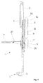
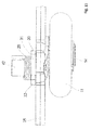
- FIG. 1 shows, in a perspective view, a sensory device 1, which consists essentially of a base element 3, which has a vertically variable in the base member 3 unit 10 with rollers 8, 9, 11.
- the vertical variability within the base element 3 is achieved by an incision 6 present in the unit 10.
- a sensor holder 5 is fixed, which has at least one sensor 2, wherein the sensor 2 always comprises a transmitting and receiving device.
- Such a sensor 2 may be formed, for example, as a light barrier or infrared or radar device.
- the rollers 8, 9, 11 On the movable unit 10, the rollers 8, 9, 11 have been arranged on a holder 7 in a substantially vertical arrangement one above the other.
- the sensory device 1 is connected via a connecting pin 27 with a panel element at its vertical edges and secured by a screw 4.
- rollers 8, 9 and 11 one above the other, in each case in different positions to each other, was carried out via axes 12, 13, 14.
- the roller 8 and the roller 11 protrude, while the middle roller 9 projects beyond the edge of the base element 3.
- the roller 11 with the axis 14 On the storage of the roller 11 with the axis 14 will be discussed separately below.
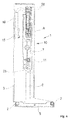
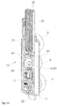
- the entire sensory device 1 is connected by the connecting mandrel 27 with the lower element of the door leaf so that in the vertical direction mobility and rotatability is possible, the fuse is made by the screw 4, which is fixed to the holder 7 , With the holder 7, a roller base 25 is further connected, on the rollers 8, 9 can be fixed directly and the rollers 11 via an eccentric bracket 31, wherein at least the roller 11 can be mounted at a distance 26 from the roller base 25.
- the holder 7 is made wider than the incision 6.
- the holder 7 is arranged on the roller base 25 distanced to the intermediate element 3 therebetween.
- On the base member 3 is also a connector 15 for electrical connection via a cable 16 for the sensors 2 is present.
- an arrangement of at least one, preferably two spring elements 28 has been shown on the back, which are formed as tension springs.
- the spring elements 28 are fastened on the one hand in the base element 3 and on the other hand on the movable holder 7.
- the base element 3 approaches the lower horizontal edge of the gate element, so that the sensor holder 5 unlocks to the lower edge of the level forth, the door leaf is then in its closed position over.
- the sensor holder 5 again comes out of the retracted position and as soon as the sensors 2 with the sensor holder 5 no longer have traction, the holder 7 in the in FIG. 4 shown basic position, withdrawn.
- the movable unit 10 consists of the holder 7 and the roller base 25 placed above and connected to it.
- the holder 7 has longitudinal guides 17, 18 extending in the longitudinal direction.
- the roller base 25 is connected to the bracket 7 by screw members, not shown.
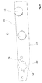
- FIG. 8 This particular placement can be especially the FIG. 8 be removed.
- the axis 12, for the upper roller 8, for example, is placed so that its diameter reaches up to an edge 45 of the roller base 25.
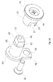
- a receptacle 35 has been shown for the eccentric bracket 31.
- a recess 36 and an opening 34 have been incorporated.
- the roller base 25 is viewed from the rear side.
- the roller 9 has been attached via a screw 37 with its axis 13 to the roller base 25.
- the roller 11 is equipped with the eccentric holder 31, which was inserted within the receptacle 35.
- the eccentric holder 31 has a projection 30 and a projection 33 which are different in their dimensions and dimensioned so that they can pass through the receptacle 35 and the opening 34 and can be rotated after insertion relative to the roller base 25.
- the spring 29 is thereby formed as a torsion spring and can due to the eccentric bracket 31 after FIG. 10 a rotational movement of the roller 11, which is mounted on a running surface 32 of the axle 14, cause.
- the spring 29 is inserted in a middle part 41 and fixed in the bore 44.
- a projection 38 is formed, which allows the roller 11 a corresponding space for this rotational movement.
- the spring 29 dives partially in the eccentric bracket 31 a.
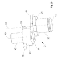
- the eccentricity of the eccentric bracket 31 is particularly in the consideration of a roller shaft 39, which passes centrally through the axis 14 and a thereto distanced shoulder axis 40, which goes through the spring bearing 42, illustrated.
- the connection between the attachment axis 40 with the projection 46 and the roller axis 39 is achieved by the molded-in central part 41.
- the eccentric holder 31 is designed, for example, as a die-cast part.
- the back of the holder 7 is shown again in a single representation.
- the spring elements 28 are embedded and the other end via holes 24 and screw connected to the bracket 7.
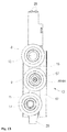
- the axes 12, 13, 14 are not located on a common reference plane in the longitudinal extent of the holder 7.
- the axes 12, 13, 14 are carried out in a roller bearing 22 and a roller bearing 23 and in a receptacle 19 via the eccentric bracket 31.
- the previously free end of the spring 29 is fixed in a bore 43 within the holder 7.
- Such a design of the holder 7 may be made of injection molding or plastic.
- the Figures 12 and 13 give a modified version of the movable unit 10 with a holder 47 again.
- This is essentially the storage of the roller 9, which can be rotated for mounting from its working position via a capping piece 51 of a setting 48 so that the rollers 8, 9, 11 are virtually on a common reference line, ie that the role of the 9th thereby according to the illustration FIG. 13 is moved to the left.
- this displacement of the roller bearing of the roller 9 is guided back again, in which the end piece 51, which is guided within a pivoting range recess 63 within the movable unit 10, turned back and then fixed by a fastening 50.
- the adjusting device 48 consists essentially of a connecting piece 64 and the end piece 51.
- the connecting piece 64 and the end piece 51 are individual components, which have an eccentric lying Tapped hole 60 and a screw 57 are connected together.
- the threaded hole 60 is present in a projection 52, which adjoins a round lug 56.
- the other end of the projection 56 forms a tab 59 of the end piece 51.
- Within the flap 59 is a bore 58 which is penetrated by the attachment 50 and fixed within the roller base 25.
- the connecting piece 64 is a rotary part which includes a bearing 49 for the roller 9, wherein the diameter of the bearing 49 and the projection 56 are equal. Centrally within the connector 64 is a bore which is penetrated by the screw 57. The outer end of the connecting piece 64 also forms a collar 53. On the other hand, the connecting piece 64 is provided with a recess 61. The recess 61 has been made dimensionally on the projection 52 with its spaced-apart sliding surfaces 62. This type of construction of the adjusting device 48 can in particular the exploded views according to FIG. 15 and 16 be removed. Due to the eccentric threaded bore 60, it is thus possible that the bearing 49 of the roller 9 can be brought from its position of use in a mounting position and back.
Landscapes
- Engineering & Computer Science (AREA)
- Mechanical Engineering (AREA)
- Power-Operated Mechanisms For Wings (AREA)
Applications Claiming Priority (1)
| Application Number | Priority Date | Filing Date | Title |
|---|---|---|---|
| DE102015100616.2A DE102015100616B3 (de) | 2015-01-16 | 2015-01-16 | Sensorische Vorrichtung |
Publications (1)
| Publication Number | Publication Date |
|---|---|
| EP3045632A1 true EP3045632A1 (fr) | 2016-07-20 |
Family
ID=54866437
Family Applications (1)
| Application Number | Title | Priority Date | Filing Date |
|---|---|---|---|
| EP16151466.6A Pending EP3045632A1 (fr) | 2015-01-16 | 2016-01-15 | Dispositif sensoriel |
Country Status (2)
| Country | Link |
|---|---|
| EP (1) | EP3045632A1 (fr) |
| DE (1) | DE102015100616B3 (fr) |
Cited By (1)
| Publication number | Priority date | Publication date | Assignee | Title |
|---|---|---|---|---|
| EP3954853A1 (fr) * | 2020-08-14 | 2022-02-16 | Alpha Deuren International BV | Plaque de liaison pour un battant de porte |
Citations (3)
| Publication number | Priority date | Publication date | Assignee | Title |
|---|---|---|---|---|
| DE10349904A1 (de) * | 2003-03-22 | 2004-10-07 | Novoferm Gmbh | Sektionaltor |
| US20050081737A1 (en) * | 2003-08-27 | 2005-04-21 | Smallwood John C. | Sectional overhead door roller assembly |
| DE102010000234B3 (de) | 2010-01-27 | 2011-03-17 | Alpha Deuren International Bv | Sektionaltor |
-
2015
- 2015-01-16 DE DE102015100616.2A patent/DE102015100616B3/de active Active
-
2016
- 2016-01-15 EP EP16151466.6A patent/EP3045632A1/fr active Pending
Patent Citations (4)
| Publication number | Priority date | Publication date | Assignee | Title |
|---|---|---|---|---|
| DE10349904A1 (de) * | 2003-03-22 | 2004-10-07 | Novoferm Gmbh | Sektionaltor |
| US20050081737A1 (en) * | 2003-08-27 | 2005-04-21 | Smallwood John C. | Sectional overhead door roller assembly |
| DE102010000234B3 (de) | 2010-01-27 | 2011-03-17 | Alpha Deuren International Bv | Sektionaltor |
| EP2354415A2 (fr) * | 2010-01-27 | 2011-08-10 | Alpha Deuren International BV | Porte sectionnelle |
Cited By (1)
| Publication number | Priority date | Publication date | Assignee | Title |
|---|---|---|---|---|
| EP3954853A1 (fr) * | 2020-08-14 | 2022-02-16 | Alpha Deuren International BV | Plaque de liaison pour un battant de porte |
Also Published As
| Publication number | Publication date |
|---|---|
| DE102015100616B3 (de) | 2016-01-07 |
Similar Documents
| Publication | Publication Date | Title |
|---|---|---|
| DE102014220837B3 (de) | Laufwagen zum leichtgängigen Abstellen eines Schiebeflügels von einem festen Rahmen eines Fensters, einer Tür oder dergleichen | |
| EP3622150B1 (fr) | Système de guidage destiné à guider une porte de meuble | |
| WO2005001226A1 (fr) | Systeme de guidage pour porte coulissante | |
| AT519903B1 (de) | Schiene zur Führung eines Schlittens einer Möbeltüre | |
| AT522465B1 (de) | Führungssystem zur Führung wenigstens eines Türflügels | |
| EP2270299B1 (fr) | Curseur destiné au raccordement d'une vitre sur un lève-glace de véhicule automobile | |
| WO2016113224A1 (fr) | Système de battants coulissants et rotatifs | |
| DE102013104420A1 (de) | Führungsanordnung einer Schiebetür, Schiebetür und Möbel | |
| EP1605125A2 (fr) | Système de guidage pour guider des portes coulissantes ou des fenêtres coulissantes | |
| EP1951977A1 (fr) | Bloc-porte mécanique pour portes, notamment pour portières de véhicule | |
| EP3045632A1 (fr) | Dispositif sensoriel | |
| EP2354415B1 (fr) | Porte sectionnelle | |
| EP3028616A1 (fr) | Porte en verre coulissante pour cabine de douche | |
| DE102016117336B3 (de) | Lagerungs-Vorrichtung eines elastisch gelagerten Torflügels | |
| EP3085281B1 (fr) | Élement coulissant destine a ranger par coulissement un rideau ou une bache | |
| DE19918283B4 (de) | Tür- oder Fensterdrehband | |
| EP3029234B1 (fr) | Ferrure d'angle réglable | |
| DE102009060144B4 (de) | Vorrichtung zur Betätigung eines Kipptors | |
| EP0853179B1 (fr) | Vantail por porte, fenêtre ou similaire | |
| DE102017000232A1 (de) | Antrieb eines Sektionaltores | |
| EP3156578B1 (fr) | Porte sectionnelle | |
| DE2727585C2 (de) | Nachstellbares Lenker-Drehlager für Kipp-Schwenkfenster oder -türen | |
| EP3095937A1 (fr) | Raccordement de vantail de porte mobile | |
| DE10323695A1 (de) | Schiebetürprofil | |
| EP2631402A2 (fr) | Liaison à articulation rotative |
Legal Events
| Date | Code | Title | Description |
|---|---|---|---|
| PUAI | Public reference made under article 153(3) epc to a published international application that has entered the european phase |
Free format text: ORIGINAL CODE: 0009012 |
|
| AK | Designated contracting states |
Kind code of ref document: A1 Designated state(s): AL AT BE BG CH CY CZ DE DK EE ES FI FR GB GR HR HU IE IS IT LI LT LU LV MC MK MT NL NO PL PT RO RS SE SI SK SM TR |
|
| AX | Request for extension of the european patent |
Extension state: BA ME |
|
| STAA | Information on the status of an ep patent application or granted ep patent |
Free format text: STATUS: REQUEST FOR EXAMINATION WAS MADE |
|
| 17P | Request for examination filed |
Effective date: 20170120 |
|
| RBV | Designated contracting states (corrected) |
Designated state(s): AL AT BE BG CH CY CZ DE DK EE ES FI FR GB GR HR HU IE IS IT LI LT LU LV MC MK MT NL NO PL PT RO RS SE SI SK SM TR |
|
| STAA | Information on the status of an ep patent application or granted ep patent |
Free format text: STATUS: EXAMINATION IS IN PROGRESS |
|
| 17Q | First examination report despatched |
Effective date: 20180803 |
|
| STAA | Information on the status of an ep patent application or granted ep patent |
Free format text: STATUS: EXAMINATION IS IN PROGRESS |
|
| STAA | Information on the status of an ep patent application or granted ep patent |
Free format text: STATUS: EXAMINATION IS IN PROGRESS |
|
| GRAP | Despatch of communication of intention to grant a patent |
Free format text: ORIGINAL CODE: EPIDOSNIGR1 |
|
| STAA | Information on the status of an ep patent application or granted ep patent |
Free format text: STATUS: GRANT OF PATENT IS INTENDED |
|
| INTG | Intention to grant announced |
Effective date: 20240403 |