EP3045632A1 - Sensor device - Google Patents
Sensor device Download PDFInfo
- Publication number
- EP3045632A1 EP3045632A1 EP16151466.6A EP16151466A EP3045632A1 EP 3045632 A1 EP3045632 A1 EP 3045632A1 EP 16151466 A EP16151466 A EP 16151466A EP 3045632 A1 EP3045632 A1 EP 3045632A1
- Authority
- EP
- European Patent Office
- Prior art keywords
- sensory device
- roller
- holder
- rollers
- spring
- Prior art date
- Legal status (The legal status is an assumption and is not a legal conclusion. Google has not performed a legal analysis and makes no representation as to the accuracy of the status listed.)
- Pending
Links
- 230000001953 sensory effect Effects 0.000 claims abstract description 49
- 238000013459 approach Methods 0.000 description 6
- 238000005553 drilling Methods 0.000 description 4
- 238000003780 insertion Methods 0.000 description 4
- 230000037431 insertion Effects 0.000 description 4
- 238000009434 installation Methods 0.000 description 3
- 238000000034 method Methods 0.000 description 3
- 230000015572 biosynthetic process Effects 0.000 description 2
- 230000004888 barrier function Effects 0.000 description 1
- 238000010276 construction Methods 0.000 description 1
- 230000001419 dependent effect Effects 0.000 description 1
- 238000013461 design Methods 0.000 description 1
- 238000006073 displacement reaction Methods 0.000 description 1
- 230000000694 effects Effects 0.000 description 1
- 210000003746 feather Anatomy 0.000 description 1
- 238000001746 injection moulding Methods 0.000 description 1
- 239000000463 material Substances 0.000 description 1
- 238000005096 rolling process Methods 0.000 description 1
- 239000000243 solution Substances 0.000 description 1
- 238000012549 training Methods 0.000 description 1
Images


Classifications
-
- E—FIXED CONSTRUCTIONS
- E05—LOCKS; KEYS; WINDOW OR DOOR FITTINGS; SAFES
- E05F—DEVICES FOR MOVING WINGS INTO OPEN OR CLOSED POSITION; CHECKS FOR WINGS; WING FITTINGS NOT OTHERWISE PROVIDED FOR, CONCERNED WITH THE FUNCTIONING OF THE WING
- E05F15/00—Power-operated mechanisms for wings
- E05F15/40—Safety devices, e.g. detection of obstructions or end positions
-
- E—FIXED CONSTRUCTIONS
- E05—LOCKS; KEYS; WINDOW OR DOOR FITTINGS; SAFES
- E05D—HINGES OR SUSPENSION DEVICES FOR DOORS, WINDOWS OR WINGS
- E05D15/00—Suspension arrangements for wings
- E05D15/16—Suspension arrangements for wings for wings sliding vertically more or less in their own plane
- E05D15/165—Details, e.g. sliding or rolling guides
-
- E—FIXED CONSTRUCTIONS
- E05—LOCKS; KEYS; WINDOW OR DOOR FITTINGS; SAFES
- E05D—HINGES OR SUSPENSION DEVICES FOR DOORS, WINDOWS OR WINGS
- E05D15/00—Suspension arrangements for wings
- E05D15/16—Suspension arrangements for wings for wings sliding vertically more or less in their own plane
- E05D15/24—Suspension arrangements for wings for wings sliding vertically more or less in their own plane consisting of parts connected at their edges
-
- E—FIXED CONSTRUCTIONS
- E05—LOCKS; KEYS; WINDOW OR DOOR FITTINGS; SAFES
- E05F—DEVICES FOR MOVING WINGS INTO OPEN OR CLOSED POSITION; CHECKS FOR WINGS; WING FITTINGS NOT OTHERWISE PROVIDED FOR, CONCERNED WITH THE FUNCTIONING OF THE WING
- E05F15/00—Power-operated mechanisms for wings
- E05F15/40—Safety devices, e.g. detection of obstructions or end positions
- E05F15/42—Detection using safety edges
- E05F15/43—Detection using safety edges responsive to disruption of energy beams, e.g. light or sound
-
- E—FIXED CONSTRUCTIONS
- E05—LOCKS; KEYS; WINDOW OR DOOR FITTINGS; SAFES
- E05F—DEVICES FOR MOVING WINGS INTO OPEN OR CLOSED POSITION; CHECKS FOR WINGS; WING FITTINGS NOT OTHERWISE PROVIDED FOR, CONCERNED WITH THE FUNCTIONING OF THE WING
- E05F15/00—Power-operated mechanisms for wings
- E05F15/60—Power-operated mechanisms for wings using electrical actuators
- E05F15/603—Power-operated mechanisms for wings using electrical actuators using rotary electromotors
- E05F15/665—Power-operated mechanisms for wings using electrical actuators using rotary electromotors for vertically-sliding wings
- E05F15/668—Power-operated mechanisms for wings using electrical actuators using rotary electromotors for vertically-sliding wings for overhead wings
-
- E—FIXED CONSTRUCTIONS
- E05—LOCKS; KEYS; WINDOW OR DOOR FITTINGS; SAFES
- E05Y—INDEXING SCHEME RELATING TO HINGES OR OTHER SUSPENSION DEVICES FOR DOORS, WINDOWS OR WINGS AND DEVICES FOR MOVING WINGS INTO OPEN OR CLOSED POSITION, CHECKS FOR WINGS AND WING FITTINGS NOT OTHERWISE PROVIDED FOR, CONCERNED WITH THE FUNCTIONING OF THE WING
- E05Y2201/00—Constructional elements; Accessories therefore
- E05Y2201/40—Motors; Magnets; Springs; Weights; Accessories therefore
- E05Y2201/47—Springs; Spring tensioners
-
- E—FIXED CONSTRUCTIONS
- E05—LOCKS; KEYS; WINDOW OR DOOR FITTINGS; SAFES
- E05Y—INDEXING SCHEME RELATING TO HINGES OR OTHER SUSPENSION DEVICES FOR DOORS, WINDOWS OR WINGS AND DEVICES FOR MOVING WINGS INTO OPEN OR CLOSED POSITION, CHECKS FOR WINGS AND WING FITTINGS NOT OTHERWISE PROVIDED FOR, CONCERNED WITH THE FUNCTIONING OF THE WING
- E05Y2201/00—Constructional elements; Accessories therefore
- E05Y2201/60—Suspension or transmission members; Accessories therefore
- E05Y2201/622—Suspension or transmission members elements
- E05Y2201/688—Rollers
-
- E—FIXED CONSTRUCTIONS
- E05—LOCKS; KEYS; WINDOW OR DOOR FITTINGS; SAFES
- E05Y—INDEXING SCHEME RELATING TO HINGES OR OTHER SUSPENSION DEVICES FOR DOORS, WINDOWS OR WINGS AND DEVICES FOR MOVING WINGS INTO OPEN OR CLOSED POSITION, CHECKS FOR WINGS AND WING FITTINGS NOT OTHERWISE PROVIDED FOR, CONCERNED WITH THE FUNCTIONING OF THE WING
- E05Y2400/00—Electronic control; Power supply; Power or signal transmission; User interfaces
- E05Y2400/10—Electronic control
- E05Y2400/30—Electronic control of motors
- E05Y2400/32—Position control, detection or monitoring
- E05Y2400/35—Position control, detection or monitoring related to specific positions
- E05Y2400/354—End positions
-
- E—FIXED CONSTRUCTIONS
- E05—LOCKS; KEYS; WINDOW OR DOOR FITTINGS; SAFES
- E05Y—INDEXING SCHEME RELATING TO HINGES OR OTHER SUSPENSION DEVICES FOR DOORS, WINDOWS OR WINGS AND DEVICES FOR MOVING WINGS INTO OPEN OR CLOSED POSITION, CHECKS FOR WINGS AND WING FITTINGS NOT OTHERWISE PROVIDED FOR, CONCERNED WITH THE FUNCTIONING OF THE WING
- E05Y2600/00—Mounting or coupling arrangements for elements provided for in this subclass
- E05Y2600/10—Adjustable or movable
- E05Y2600/13—Adjustable or movable by motors, magnets, springs, weights
-
- E—FIXED CONSTRUCTIONS
- E05—LOCKS; KEYS; WINDOW OR DOOR FITTINGS; SAFES
- E05Y—INDEXING SCHEME RELATING TO HINGES OR OTHER SUSPENSION DEVICES FOR DOORS, WINDOWS OR WINGS AND DEVICES FOR MOVING WINGS INTO OPEN OR CLOSED POSITION, CHECKS FOR WINGS AND WING FITTINGS NOT OTHERWISE PROVIDED FOR, CONCERNED WITH THE FUNCTIONING OF THE WING
- E05Y2600/00—Mounting or coupling arrangements for elements provided for in this subclass
- E05Y2600/40—Mounting location; Visibility of the elements
- E05Y2600/46—Mounting location; Visibility of the elements in or on the wing
-
- E—FIXED CONSTRUCTIONS
- E05—LOCKS; KEYS; WINDOW OR DOOR FITTINGS; SAFES
- E05Y—INDEXING SCHEME RELATING TO HINGES OR OTHER SUSPENSION DEVICES FOR DOORS, WINDOWS OR WINGS AND DEVICES FOR MOVING WINGS INTO OPEN OR CLOSED POSITION, CHECKS FOR WINGS AND WING FITTINGS NOT OTHERWISE PROVIDED FOR, CONCERNED WITH THE FUNCTIONING OF THE WING
- E05Y2600/00—Mounting or coupling arrangements for elements provided for in this subclass
- E05Y2600/60—Mounting or coupling members; Accessories therefore
- E05Y2600/626—Plates or brackets
-
- E—FIXED CONSTRUCTIONS
- E05—LOCKS; KEYS; WINDOW OR DOOR FITTINGS; SAFES
- E05Y—INDEXING SCHEME RELATING TO HINGES OR OTHER SUSPENSION DEVICES FOR DOORS, WINDOWS OR WINGS AND DEVICES FOR MOVING WINGS INTO OPEN OR CLOSED POSITION, CHECKS FOR WINGS AND WING FITTINGS NOT OTHERWISE PROVIDED FOR, CONCERNED WITH THE FUNCTIONING OF THE WING
- E05Y2900/00—Application of doors, windows, wings or fittings thereof
- E05Y2900/10—Application of doors, windows, wings or fittings thereof for buildings or parts thereof
- E05Y2900/106—Application of doors, windows, wings or fittings thereof for buildings or parts thereof for garages
Definitions
- the invention relates to a sensory device having at least one sensor which comprises a transmitting and receiving device for securing the closing edge of a door leaf, which is formed of a plurality of mutually hingedly connected elements.
- the DE 10 2010 000 234 B3 describes a sectional door with individual, mutually pivotally connected section elements, which are guided and moved in laterally arranged rails by means of rollers.
- a storable, non-contact sensor in the form of a sensory device for detecting objects or persons in the region of the movement path of the section elements is provided on the sectional door leaf in such a way that a holder is provided which is in a space between the running rail and a lateral section element edge is placed. This holder is moved over roller elements, which are also guided within the track.
- the object of the invention is to improve the sensory device to the effect that a greater positional accuracy is achieved during the mobility of the door leaf. Furthermore, this sensory device should be easy to assemble.
- the sensory device is equipped with at least one transmitting and receiving device for securing the closing edge of a sectional door, spiral door or another type of door.
- the device is placed between at least one vertical edge, preferably on both vertical edges of the lower element of a door leaf and the laterally thereto, substantially vertically aligned, fixed guide rails.
- About a connection is the sensory device connected to the lowermost element of the door leaf so that rotational movements and vertical movements are possible.
- Such a connection ensures that the device can work safely and thus can ensure an accurate protection of the area below the element edge, namely the main closing edge of the door leaf.
- existing tolerances resulting from the installation of such a door leaf can be compensated by the special mounting method and the structure of the device.
- the assembly of the sensory device is pivotally connected to a base element.
- This basic element is equipped with a displaceable in the translational direction unit and can be moved by rolling within guide rails.
- the sensory device for stable positional compliance has an arrangement of three rollers. These rollers are mounted substantially in vertical alignment with each other on the unit. By this vertical arrangement, the placement of the rollers is carried out so that no common vertical line is assigned to the three rollers with their axes, it creates a kind of three-point storage.
- the lowermost of the three rollers on the unit is provided with a non-rigid axle.
- a non-rigid axle Such an axis is rotatable and thereby changeable at least in another direction.
- Such an embodiment can be achieved by an eccentric holder which is subject to error.
- the mobility facilitates insertion into the lateral guide rails, because during rotation the lower axle bearing can be brought out of its position of use.
- the middle of the roll is provided with a device which allows, for mounting in the guide rail, this middle roll is brought out of its use position. This can be done for example by an adjustment of the axis.
- a device which allows, for mounting in the guide rail this middle roll is brought out of its use position.
- This can be done for example by an adjustment of the axis.
- provided with an eccentric bearing arrangement of the middle roller is brought out of the position of use. After installation of the sensory device within the lateral guide the storage of the middle roller is returned to its position of use and fixed there.
- a greater distance from the roller base has been carried out.
- This special storage of the three rollers an even more efficient stability of the sensory devices in the course of their vertical movements in a drive of the door leaf from the closed position is reached in an open position and back. This is due to the fact that when using guide rails which have a cross-sectionally a J-profile or even a C-profile, the three-point bearing, the sensory device assumes a stable position.
- the spring-loaded roller ensures in any case that the rollers in the profile of the guide rails exert a sufficient pressure on the inner walls of the profile.
- the sensory device is vertically adjustable, the choice of roller bearings achieves an extremely stable condition. This is always safe even with curves, as it is given for example between the substantially vertical and substantially horizontal extension of the guide rails.
- This constant contact is also increased by the fact that the lower arranged on the eccentric mounting movable roller opposite the rollers placed above has a further distance from the roller base. As a result, this role is always pressed into the guide rail, so that a blurring of the sensory device in the process of the door leaf can not occur.
- For mounting it is possible to place the middle roller on an eccentrically mounted, adjustable axle. After assembly, the roller is fixed again with its chosen distance to the other rollers.
- Such a trained sensory device is also suitable, for example, in high-speed spiral doors, which may be similar in their Tor-sheet the sectional doors, without problems to be applied.
- the attachment of the three superimposed rollers is performed on a moving unit.
- This unit is arranged displaceably in a section of the base element.
- This displaceable arrangement is loaded by at least one spring element, so that upon impact of the sensory device on an obstacle, or the floor, the sensory device is virtually displaced laterally into the space between the element and the guide rail within the base element.
- the sensory device is automatically pushed out of its "parking position" again.
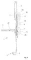
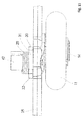
- FIG. 1 shows, in a perspective view, a sensory device 1, which consists essentially of a base element 3, which has a vertically variable in the base member 3 unit 10 with rollers 8, 9, 11.
- the vertical variability within the base element 3 is achieved by an incision 6 present in the unit 10.
- a sensor holder 5 is fixed, which has at least one sensor 2, wherein the sensor 2 always comprises a transmitting and receiving device.
- Such a sensor 2 may be formed, for example, as a light barrier or infrared or radar device.
- the rollers 8, 9, 11 On the movable unit 10, the rollers 8, 9, 11 have been arranged on a holder 7 in a substantially vertical arrangement one above the other.
- the sensory device 1 is connected via a connecting pin 27 with a panel element at its vertical edges and secured by a screw 4.
- rollers 8, 9 and 11 one above the other, in each case in different positions to each other, was carried out via axes 12, 13, 14.
- the roller 8 and the roller 11 protrude, while the middle roller 9 projects beyond the edge of the base element 3.
- the roller 11 with the axis 14 On the storage of the roller 11 with the axis 14 will be discussed separately below.
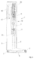
- the entire sensory device 1 is connected by the connecting mandrel 27 with the lower element of the door leaf so that in the vertical direction mobility and rotatability is possible, the fuse is made by the screw 4, which is fixed to the holder 7 , With the holder 7, a roller base 25 is further connected, on the rollers 8, 9 can be fixed directly and the rollers 11 via an eccentric bracket 31, wherein at least the roller 11 can be mounted at a distance 26 from the roller base 25.
- the holder 7 is made wider than the incision 6.
- the holder 7 is arranged on the roller base 25 distanced to the intermediate element 3 therebetween.
- On the base member 3 is also a connector 15 for electrical connection via a cable 16 for the sensors 2 is present.
- an arrangement of at least one, preferably two spring elements 28 has been shown on the back, which are formed as tension springs.
- the spring elements 28 are fastened on the one hand in the base element 3 and on the other hand on the movable holder 7.
- the base element 3 approaches the lower horizontal edge of the gate element, so that the sensor holder 5 unlocks to the lower edge of the level forth, the door leaf is then in its closed position over.
- the sensor holder 5 again comes out of the retracted position and as soon as the sensors 2 with the sensor holder 5 no longer have traction, the holder 7 in the in FIG. 4 shown basic position, withdrawn.
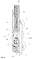
- the movable unit 10 consists of the holder 7 and the roller base 25 placed above and connected to it.
- the holder 7 has longitudinal guides 17, 18 extending in the longitudinal direction.
- the roller base 25 is connected to the bracket 7 by screw members, not shown.
- FIG. 8 This particular placement can be especially the FIG. 8 be removed.
- the axis 12, for the upper roller 8, for example, is placed so that its diameter reaches up to an edge 45 of the roller base 25.
- a receptacle 35 has been shown for the eccentric bracket 31.
- a recess 36 and an opening 34 have been incorporated.
- the roller base 25 is viewed from the rear side.
- the roller 9 has been attached via a screw 37 with its axis 13 to the roller base 25.
- the roller 11 is equipped with the eccentric holder 31, which was inserted within the receptacle 35.
- the eccentric holder 31 has a projection 30 and a projection 33 which are different in their dimensions and dimensioned so that they can pass through the receptacle 35 and the opening 34 and can be rotated after insertion relative to the roller base 25.
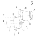
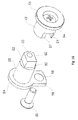
- the spring 29 is thereby formed as a torsion spring and can due to the eccentric bracket 31 after FIG. 10 a rotational movement of the roller 11, which is mounted on a running surface 32 of the axle 14, cause.
- the spring 29 is inserted in a middle part 41 and fixed in the bore 44.
- a projection 38 is formed, which allows the roller 11 a corresponding space for this rotational movement.
- the spring 29 dives partially in the eccentric bracket 31 a.
- the eccentricity of the eccentric bracket 31 is particularly in the consideration of a roller shaft 39, which passes centrally through the axis 14 and a thereto distanced shoulder axis 40, which goes through the spring bearing 42, illustrated.
- the connection between the attachment axis 40 with the projection 46 and the roller axis 39 is achieved by the molded-in central part 41.
- the eccentric holder 31 is designed, for example, as a die-cast part.
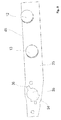
- the back of the holder 7 is shown again in a single representation.
- the spring elements 28 are embedded and the other end via holes 24 and screw connected to the bracket 7.
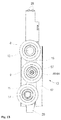
- the axes 12, 13, 14 are not located on a common reference plane in the longitudinal extent of the holder 7.
- the axes 12, 13, 14 are carried out in a roller bearing 22 and a roller bearing 23 and in a receptacle 19 via the eccentric bracket 31.
- the previously free end of the spring 29 is fixed in a bore 43 within the holder 7.
- Such a design of the holder 7 may be made of injection molding or plastic.
- the Figures 12 and 13 give a modified version of the movable unit 10 with a holder 47 again.
- This is essentially the storage of the roller 9, which can be rotated for mounting from its working position via a capping piece 51 of a setting 48 so that the rollers 8, 9, 11 are virtually on a common reference line, ie that the role of the 9th thereby according to the illustration FIG. 13 is moved to the left.
- this displacement of the roller bearing of the roller 9 is guided back again, in which the end piece 51, which is guided within a pivoting range recess 63 within the movable unit 10, turned back and then fixed by a fastening 50.
- the adjusting device 48 consists essentially of a connecting piece 64 and the end piece 51.
- the connecting piece 64 and the end piece 51 are individual components, which have an eccentric lying Tapped hole 60 and a screw 57 are connected together.
- the threaded hole 60 is present in a projection 52, which adjoins a round lug 56.
- the other end of the projection 56 forms a tab 59 of the end piece 51.
- Within the flap 59 is a bore 58 which is penetrated by the attachment 50 and fixed within the roller base 25.
- the connecting piece 64 is a rotary part which includes a bearing 49 for the roller 9, wherein the diameter of the bearing 49 and the projection 56 are equal. Centrally within the connector 64 is a bore which is penetrated by the screw 57. The outer end of the connecting piece 64 also forms a collar 53. On the other hand, the connecting piece 64 is provided with a recess 61. The recess 61 has been made dimensionally on the projection 52 with its spaced-apart sliding surfaces 62. This type of construction of the adjusting device 48 can in particular the exploded views according to FIG. 15 and 16 be removed. Due to the eccentric threaded bore 60, it is thus possible that the bearing 49 of the roller 9 can be brought from its position of use in a mounting position and back.
Abstract
Die Erfindung betrifft eine sensorische Vorrichtung (1) mit mindestens einem Sensor (2), der eine Sende- und Empfangseinrichtung zur Absicherung der Schüeßkante eines Torblattes aufweist, das aus mehreren, untereinander gelenkig verbundenen Elementen besteht, die durch Rollen (8,11) in seitlichen Führungen ortsveränderbar sind, wobei die sensorische Vorrichtung (1) zwischen seitlichen Kanten des unteren Elementes auf mindestens einer Seite des Torblattes und der zugehörigen Führung platziert ist, und dass mit dem unteren Element des Torblattes über einen Verbindungsdorn (27) ein Grundelement (3) befestigt ist, wobei innerhalb des Grundelementes (3) in einem Einschnitt (6) verschieblich eine Einheit (10) enthalten ist, wobei die Einheit (10) Rollen (8, 9, 11) aufweist, die in vertikaler Ausrichtung untereinander so angeordnet sind, dass den Rollen (8, 9, 11) keine gemeinsame vertikale Verbindungslinie zugeordnet wird und die Rolle (11) beweglich gelagert ist.The invention relates to a sensory device (1) having at least one sensor (2) having a transmitting and receiving device for securing the Schüeßkante a Torblattes, which consists of several mutually articulated elements connected by rollers (8,11) in lateral guides are locally variable, wherein the sensory device (1) is placed between lateral edges of the lower element on at least one side of the door leaf and the associated guide, and that with the lower element of the door leaf via a connecting mandrel (27) has a base element (3) in which a unit (10) is displaceably contained in a recess (6) within the base element (3), the unit (10) having rollers (8, 9, 11) arranged in vertical alignment with one another, that the rollers (8, 9, 11) no common vertical connection line is assigned and the roller (11) is movably mounted.
Description
Die Erfindung betrifft eine sensorische Vorrichtung mit mindestens einem Sensor, der über eine Sende- und Empfangseinrichtung zur Absicherung der Schließkante eines Torblattes besteht, das aus mehreren, untereinander gelenkig verbundenen Elementen gebildet wird.The invention relates to a sensory device having at least one sensor which comprises a transmitting and receiving device for securing the closing edge of a door leaf, which is formed of a plurality of mutually hingedly connected elements.
Die
Die Aufgabe der Erfindung besteht darin, die sensorische Vorrichtung dahingehend zu verbessern, dass eine größere Lagegenauigkeit während der Verfahrbarkeit des Torblattes erreicht wird. Ferner soll diese sensorische Vorrichtung einfach montierbar sein.The object of the invention is to improve the sensory device to the effect that a greater positional accuracy is achieved during the mobility of the door leaf. Furthermore, this sensory device should be easy to assemble.
Die Lösung der Erfindung wird mit den Merkmalen des Anspruches 1 erzielt. Die Unteransprüche geben dabei eine weitere Ausgestaltung des erfindungsgemäßen Gedankens wieder.The solution of the invention is achieved with the features of
Die sensorische Vorrichtung ist mit mindestens einer Sende- und Emp-fangseinrichtung zur Absicherung der Schließkante eines Sektionalto-res, Spiraltores oder eines anderen Tortyps ausgestattet. Die Vorrichtung wird zwischen mindestens einer vertikalen Kante, vorzugsweise an beiden vertikalen Kanten des unteren Elementes eines Torblattes und den seitlich dazu, im Wesentlichen vertikal ausgerichteten, ortsfesten Führungsschienen platziert. Über eine Verbindung ist dabei die sensorische Vorrichtung mit dem untersten Element des Torblattes so verbunden, dass Drehbewegungen und Vertikalbewegungen möglich sind. Durch eine derartige Verbindung wird sichergestellt, dass die Vorrichtung sicher arbeiten kann und somit eine genaue Absicherung des Bereiches unterhalb der Elementkante, nämlich der Hauptschließkante des Torblattes, absichern kann. Ferner können durch die besondere Montageart und den Aufbau der Vorrichtung vorhandene Toleranzen, die sich durch die Montage eines derartigen Torblattes ergeben, ausgeglichen werden.The sensory device is equipped with at least one transmitting and receiving device for securing the closing edge of a sectional door, spiral door or another type of door. The device is placed between at least one vertical edge, preferably on both vertical edges of the lower element of a door leaf and the laterally thereto, substantially vertically aligned, fixed guide rails. About a connection is the sensory device connected to the lowermost element of the door leaf so that rotational movements and vertical movements are possible. Such a connection ensures that the device can work safely and thus can ensure an accurate protection of the area below the element edge, namely the main closing edge of the door leaf. Furthermore, existing tolerances resulting from the installation of such a door leaf can be compensated by the special mounting method and the structure of the device.
Die Montage der sensorischen Vorrichtung erfolgt drehgelenkig an einem Grundelement. Dieses Grundelement ist mit einer in translatorischer Richtung verschieblichen Einheit ausgestattet und durch Rollen innerhalb von Führungsschienen ortsveränderbar. Um die Lagerung innerhalb von Führungsschienen zu stabilisieren, weist die sensorische Vorrichtung zur stabilen Positionseinhaltung eine Anordnung von drei Rollen auf. Diese Rollen sind im Wesentlichen in vertikaler Anordnung untereinander an der Einheit befestigt. Durch diese vertikale Anordnung wird die Platzierung der Rollen so ausgeführt, dass keine gemeinsame vertikale Linie den drei Rollen mit ihren Achsen zugeordnet wird, es entsteht quasi eine Dreipunktlagerung.The assembly of the sensory device is pivotally connected to a base element. This basic element is equipped with a displaceable in the translational direction unit and can be moved by rolling within guide rails. In order to stabilize the bearing within guide rails, the sensory device for stable positional compliance has an arrangement of three rollers. These rollers are mounted substantially in vertical alignment with each other on the unit. By this vertical arrangement, the placement of the rollers is carried out so that no common vertical line is assigned to the three rollers with their axes, it creates a kind of three-point storage.
In einer bevorzugten Ausführungsform ist darüber hinaus die unterste der drei Rollen an der Einheit mit einer nicht starren Achse ausgestattet. Eine solche Achse ist verdrehbar und dabei zumindest in einer weiteren Richtung veränderbar. Eine derartige Ausführung kann durch einen Exzenterhalter, der fehlerbelastet ist, erzielt werden. Durch die Beweg-lichkeit wird das Einsetzen in die seitlichen Führungsschienen erleichtert, weil während der Verdrehung die untere Achslagerung aus ihrer Gebrauchslage herausgebracht werden kann.In a preferred embodiment, moreover, the lowermost of the three rollers on the unit is provided with a non-rigid axle. Such an axis is rotatable and thereby changeable at least in another direction. Such an embodiment can be achieved by an eccentric holder which is subject to error. The mobility facilitates insertion into the lateral guide rails, because during rotation the lower axle bearing can be brought out of its position of use.
In einer weiteren bevorzugten Ausführungsform ist es möglich, dass zu-sätzlich oder ausschließlich die mittlere der Rolle mit einer Vorrichtung versehen ist, die es gestattet, dass zur Montage in die Führungsschiene diese mittlere Rolle aus ihrer Gebrauchslage heraus gebracht wird. Dieses kann beispielsweise durch eine Verstellung der Achse ausgeführt werden. Dabei wird die mit einer Exzenterlagerung versehene Anordnung der mittleren Rolle aus der Gebrauchslage heraus gebracht. Nach erfolgter Montage der sensorischen Vorrichtung innerhalb der seitlichen Führung wird die Lagerung der mittleren Rolle in ihre Gebrauchslage zurückgestellt und dort festgesetzt.In a further preferred embodiment, it is possible that additionally or exclusively, the middle of the roll is provided with a device which allows, for mounting in the guide rail, this middle roll is brought out of its use position. This can be done for example by an adjustment of the axis. In this case, provided with an eccentric bearing arrangement of the middle roller is brought out of the position of use. After installation of the sensory device within the lateral guide the storage of the middle roller is returned to its position of use and fixed there.
Neben den unterschiedlichen Platzierungen weist die Anordnung der Rollen noch eine weitere Veränderung gegenüber den bisher üblichen Befestigungen von Rollen auf. Diese besteht beispielsweise darin, dass die oberen beiden Rollen auf einer festen Achse einen gleichen Abstand zu einer Rollenbasis haben, auf der diese Achsen befestigt sind. Bei der unteren, durch die Exzenterhalterung gelagerten Rolle ist darüber hin-aus noch ein größerer Abstand zu der Rollenbasis ausgeführt worden. Durch diese spezielle Lagerung der drei Rollen wird eine noch effizientere Stabilität der sensorischen Vorrichtungen im Zuge ihrer vertikalen Bewegungen bei einer Fahrt des Torblattes aus der Schließstellung in eine Offenstellung und zurück erreicht. Dieses liegt daran, dass bei einer Verwendung von Führungsschienen, die im Querschnitt ein J-Profil oder aber auch ein C-Profil beinhalten, durch die Dreipunktlagerung die sensorische Vorrichtung eine stabile Lage einnimmt. Durch die federbelastete Rolle ist in jedem Falle sichergestellt, dass die Rollen in dem Profil der Führungsschienen einen genügenden Andruck auf die Innenwände des Profils ausüben. Durch die Wahl der Rollenplatzierung übereinander wird stets sichergestellt, dass die Rollen mit den Innenseiten der Führungsschienen in Kontakt stehen. Obwohl die sensorische Vorrichtung vertikal veränderbar ist, wird durch die Wahl der Rollenlagerung ein äußerst stabiler Zustand erzielt. Dieses ist auch bei Kurven, wie sie beispielsweise zwischen der im Wesentlichen vertikalen und im Wesentlichen horizontalen Erstreckung der Führungs-schienen gegeben ist, stets sicher ausgeführt. Dieser ständige Kontakt wird auch dadurch erhöht, dass die untere auf der Exzenterhalterung angeordnete bewegliche Rolle gegenüber den darüber platzierten Rollen einen weiteren Abstand von der Rollenbasis aufweist. Dadurch wird diese Rolle stets in die Führungsschiene gedrückt, so dass ein Verwackeln der sensorischen Vorrichtung beim Verfahren des Torblattes nicht auftreten kann. Zur Montage ist es möglich, die mittlere Rolle auch auf einer exzentrisch gelagerten, verstellbaren Achse zu platzieren. Nach der Montage wird die Rolle mit ihrem gewählten Abstand zu den anderen Rollen wieder festgesetzt.In addition to the different placements, the arrangement of the rollers on a further change compared to the usual fortifications of roles. This is, for example, that the top two rollers on a fixed axis at an equal distance a roller base on which these axles are mounted. In addition, at the lower roller mounted by the eccentric support, a greater distance from the roller base has been carried out. This special storage of the three rollers an even more efficient stability of the sensory devices in the course of their vertical movements in a drive of the door leaf from the closed position is reached in an open position and back. This is due to the fact that when using guide rails which have a cross-sectionally a J-profile or even a C-profile, the three-point bearing, the sensory device assumes a stable position. The spring-loaded roller ensures in any case that the rollers in the profile of the guide rails exert a sufficient pressure on the inner walls of the profile. By choosing the role placement on top of each other is always ensured that the rollers are in contact with the inner sides of the guide rails. Although the sensory device is vertically adjustable, the choice of roller bearings achieves an extremely stable condition. This is always safe even with curves, as it is given for example between the substantially vertical and substantially horizontal extension of the guide rails. This constant contact is also increased by the fact that the lower arranged on the eccentric mounting movable roller opposite the rollers placed above has a further distance from the roller base. As a result, this role is always pressed into the guide rail, so that a blurring of the sensory device in the process of the door leaf can not occur. For mounting it is possible to place the middle roller on an eccentrically mounted, adjustable axle. After assembly, the roller is fixed again with its chosen distance to the other rollers.
Eine derartig ausgebildete sensorische Vorrichtung ist auch geeignet, beispielsweise bei schnell laufenden Spiraltoren, die in ihrem Tor-blattaufbau den Sektionaltoren ähnlich sein können, ohne Probleme angewendet werden zu können.Such a trained sensory device is also suitable, for example, in high-speed spiral doors, which may be similar in their Tor-sheet the sectional doors, without problems to be applied.
Die Befestigung der drei übereinander angeordneten Rollen wird auf einer beweglichen Einheit durchgeführt. Diese Einheit ist in einem Ein-schnitt des Grundelementes verschieblich angeordnet. Diese verschiebliche Anordnung wird durch mindestens ein Federelement belastet, so dass beim Auftreffen der sensorischen Vorrichtung auf ein Hindernis, bzw. den Fußboden, die sensorische Vorrichtung quasi seitlich in den Zwischenraum zwischen dem Element und der Führungsschiene nach oben innerhalb des Grundelementes verschoben wird. Beim Öffnungsvorgang wird aufgrund der Federbelastung automatisch die sensorische Vorrichtung aus ihrer "Parkposition" wieder herausgedrückt.The attachment of the three superimposed rollers is performed on a moving unit. This unit is arranged displaceably in a section of the base element. This displaceable arrangement is loaded by at least one spring element, so that upon impact of the sensory device on an obstacle, or the floor, the sensory device is virtually displaced laterally into the space between the element and the guide rail within the base element. During the opening process, due to the spring load, the sensory device is automatically pushed out of its "parking position" again.
Weitere Vorteile, Merkmale und Anwendungsmöglichkeiten der vorliegenden Erfindung ergeben sich aus der nachfolgenden Beschreibung in Verbindung mit den in den Zeichnungen dargestellten Ausführungsbeispielen.Further advantages, features and possible applications of the present invention will become apparent from the following description in conjunction with the embodiments illustrated in the drawings.
In der Beschreibung, in den Ansprüchen und den Zeichnungen werden die in der aufgeführten Liste der Bezugszeichen verwendeten Begriffe und zugeordneten Bezugszeichen verwendet. In der Zeichnung bedeutet:
- Fig. 1
- Eine perspektivische Ansicht einer sensorischen Vorrichtung;
- Fig 2
- wie
Figur 1 - Fig. 3
- wie
Figur 1 - Fig. 4
- wie
Figur 2 - Fig. 5
- eine Ausschnittdarstellung einer beweglichen Einheit mit Rollen in einer perspektivischen Ansicht;
- Fig. 6
- wie
Figur 5 - Fig. 7
- einen Teilausschnitt der Lagerung der unteren Rolle;
- Fig. 8
- eine Ausbildung einer Rollenbasis;
- Fig. 9
- eine Rückansicht einer verschieblichen Halterung in einer bevorzugten Ausführungsform;
- Fig. 10
- eine perspektivische Darstellung einer Exzenterhalterung;
- Fig. 11
- eine Verwendung der Exzenterhalterung nach
Figur 10 ; - Fig. 12
- eine Rückansicht der verschieblichen Halterung in einer weiteren bevorzugten Ausführungsform;
- Fig. 13
- eine Ausschnittdarstellung der beweglichen Einheit in einer weiteren bevorzugten Ausführungsform;
- Fig. 14
- eine perspektivische Darstellung einer Einstellvorrichtung für eine Rolle;
- Fig. 15
wie Figur 14 , jedoch in einer Explosionsdarstellung und- Fig. 16
wie Figur 15 , jedoch aus einer andere Betrachtungsrichtung.
- Fig. 1
- A perspective view of a sensory device;
- Fig. 2
- as
FIG. 1 but in front view; - Fig. 3
- as
FIG. 1 but in side view; - Fig. 4
- as
FIG. 2 but in a rear view; - Fig. 5
- a detail view of a movable unit with rollers in a perspective view;
- Fig. 6
- as
FIG. 5 but in a plan view; - Fig. 7
- a partial section of the storage of the lower roller;
- Fig. 8
- a training of a role basis;
- Fig. 9
- a rear view of a sliding support in a preferred embodiment;
- Fig. 10
- a perspective view of an eccentric holder;
- Fig. 11
- a use of the eccentric bracket after
FIG. 10 ; - Fig. 12
- a rear view of the sliding holder in a further preferred embodiment;
- Fig. 13
- a detail view of the movable unit in a further preferred embodiment;
- Fig. 14
- a perspective view of a setting device for a roll;
- Fig. 15
- as
FIG. 14 , but in an exploded view and - Fig. 16
- as
FIG. 15 but from a different perspective.
Die
Durch die Darstellung nach
Durch die
Bei der rückseitigen Betrachtung der sensorischen Vorrichtung 1 in der
In der
In der Darstellung der
Diese besondere Platzierung kann insbesondere auch der
In der
Durch die Seitenansicht nach
In der
Die
- 11
- Sensorische VorrichtungSensory device
- 22
- Sensorsensor
- 33
- Grundelementbasic element
- 44
- Schraubescrew
- 55
- Sensorhalterungsensor mount
- 66
- Einschnittincision
- 77
- Halterungbracket
- 88th
- Obere RolleUpper role
- 99
- Mittlerer RolleMedium role
- 1010
- Bewegliche EinheitMobile unit
- 1111
- Untere RolleLower roll
- 1212
- Achseaxis
- 1313
- Achseaxis
- 1414
- Achseaxis
- 1515
- Steckverbindungconnector
- 1616
- Kabelelectric wire
- 1717
- Führungguide
- 1818
- Führungguide
- 1919
- Aufnahmeadmission
- 2020
- Federaufnahmespring mount
- 2121
- Kabelführungcable management
- 2222
- Rollenlagerungroller bearing
- 2323
- Rollenlagerungroller bearing
- 2424
- Bohrungdrilling
- 2525
- Rollenbasisrole-based
- 2626
- Distanzdistance
- 2727
- Verbindungsdornconnecting mandrel
- 2828
- Federelementspring element
- 2929
- Federfeather
- 3030
- Vorsprunghead Start
- 3131
- ExzenterhalterungExzenterhalterung
- 3232
- Laufflächetread
- 3333
- Vorsprunghead Start
- 3434
- Durchbruchbreakthrough
- 3535
- Aufnahmeadmission
- 3636
- Vertiefungdeepening
- 3737
- Verschraubungscrew
- 3838
- Vorsprunghead Start
- 3939
- Rollenachseroller axis
- 4040
- Ansatzachseapproach axis
- 4141
- Mittenteilmiddle part
- 4242
- Federlagerspring camp
- 4343
- Bohrungdrilling
- 4444
- Bohrungdrilling
- 4545
- Randedge
- 4646
- Ansatzapproach
- 4747
- Halterungbracket
- 4848
- Einstellvorrichtungadjustment
- 4949
- Lagerungstorage
- 5050
- Befestigungattachment
- 5151
- Abschlussstückterminating piece
- 5252
- Ansatzapproach
- 5353
- BundFederation
- 5454
- BundFederation
- 5555
- Werkzeugansatztool attachment
- 5656
- Ansatzapproach
- 5757
- Schraubescrew
- 5858
- Bohrungdrilling
- 5959
- Lascheflap
- 6060
- Gewindebohrungthreaded hole
- 6161
- Ausnehmungrecess
- 6262
- Gleitflächensliding surfaces
- 6363
- SchwenkbereichsvertiefungSwivel range recess
- 6464
- Verbindungsstückjoint
Claims (17)
Applications Claiming Priority (1)
| Application Number | Priority Date | Filing Date | Title |
|---|---|---|---|
| DE102015100616.2A DE102015100616B3 (en) | 2015-01-16 | 2015-01-16 | Sensory device |
Publications (1)
| Publication Number | Publication Date |
|---|---|
| EP3045632A1 true EP3045632A1 (en) | 2016-07-20 |
Family
ID=54866437
Family Applications (1)
| Application Number | Title | Priority Date | Filing Date |
|---|---|---|---|
| EP16151466.6A Pending EP3045632A1 (en) | 2015-01-16 | 2016-01-15 | Sensor device |
Country Status (2)
| Country | Link |
|---|---|
| EP (1) | EP3045632A1 (en) |
| DE (1) | DE102015100616B3 (en) |
Cited By (1)
| Publication number | Priority date | Publication date | Assignee | Title |
|---|---|---|---|---|
| EP3954853A1 (en) * | 2020-08-14 | 2022-02-16 | Alpha Deuren International BV | Connection plate for a door leaf |
Citations (3)
| Publication number | Priority date | Publication date | Assignee | Title |
|---|---|---|---|---|
| DE10349904A1 (en) * | 2003-03-22 | 2004-10-07 | Novoferm Gmbh | Sectional door for use as sliding garage door, has electrical door drive coupled to door panel that opens and closes movement of door panel, and driven impeller that engages in guide rail and moves panel along rail |
| US20050081737A1 (en) * | 2003-08-27 | 2005-04-21 | Smallwood John C. | Sectional overhead door roller assembly |
| DE102010000234B3 (en) | 2010-01-27 | 2011-03-17 | Alpha Deuren International Bv | sectional |
-
2015
- 2015-01-16 DE DE102015100616.2A patent/DE102015100616B3/en active Active
-
2016
- 2016-01-15 EP EP16151466.6A patent/EP3045632A1/en active Pending
Patent Citations (4)
| Publication number | Priority date | Publication date | Assignee | Title |
|---|---|---|---|---|
| DE10349904A1 (en) * | 2003-03-22 | 2004-10-07 | Novoferm Gmbh | Sectional door for use as sliding garage door, has electrical door drive coupled to door panel that opens and closes movement of door panel, and driven impeller that engages in guide rail and moves panel along rail |
| US20050081737A1 (en) * | 2003-08-27 | 2005-04-21 | Smallwood John C. | Sectional overhead door roller assembly |
| DE102010000234B3 (en) | 2010-01-27 | 2011-03-17 | Alpha Deuren International Bv | sectional |
| EP2354415A2 (en) * | 2010-01-27 | 2011-08-10 | Alpha Deuren International BV | Sectional gate |
Cited By (1)
| Publication number | Priority date | Publication date | Assignee | Title |
|---|---|---|---|---|
| EP3954853A1 (en) * | 2020-08-14 | 2022-02-16 | Alpha Deuren International BV | Connection plate for a door leaf |
Also Published As
| Publication number | Publication date |
|---|---|
| DE102015100616B3 (en) | 2016-01-07 |
Similar Documents
| Publication | Publication Date | Title |
|---|---|---|
| EP3207200B1 (en) | Trolley of a movable sliding sash | |
| EP3622150B1 (en) | Guide system for guiding a furniture door | |
| EP1641992A1 (en) | Guide device for a sliding door | |
| AT519903B1 (en) | Rail for guiding a slide of a furniture door | |
| EP2270299B1 (en) | Carrier for fixing a window pane to a window lifter of a motor vehicle | |
| AT522465B1 (en) | Guide system for guiding at least one door leaf | |
| DE102009027242B4 (en) | Movable partition | |
| WO2016113224A1 (en) | Slide and swing leaf/sash system | |
| DE102013104420A1 (en) | Guide arrangement of a sliding door, sliding door and furniture | |
| EP1605125A2 (en) | Guiding system for guiding sliding doors or sliding windows | |
| EP1951977A1 (en) | Mechanical door stop for doors, in particular vehicle doors | |
| EP3045632A1 (en) | Sensor device | |
| EP2354415B1 (en) | Sectional gate | |
| EP3028616A1 (en) | Glass pane door for a shower cubicle | |
| DE102016117336B3 (en) | Storage device of an elastically mounted gate leaf | |
| EP3085281B1 (en) | Sliding element for displaceable storage of a curtain or a tarpaulin | |
| DE19918283B4 (en) | Door or window hinge | |
| EP3029234B1 (en) | Adjustable corner fitting | |
| DE102009060144B4 (en) | Device for actuating a tilt gate | |
| EP0853179B1 (en) | Wing for a door or window or the like | |
| DE102017000232A1 (en) | Drive a sectional door | |
| EP3156578B1 (en) | Sectional gate | |
| DE2727585C2 (en) | Adjustable handlebar pivot bearing for bottom-hung windows or doors | |
| EP3095937A1 (en) | Connection for a mobile gate leaf | |
| DE10323695A1 (en) | Sliding door profile has fixing rail and track rail fixed thereon by retaining webs engaging in recesses and secured by screw |
Legal Events
| Date | Code | Title | Description |
|---|---|---|---|
| PUAI | Public reference made under article 153(3) epc to a published international application that has entered the european phase |
Free format text: ORIGINAL CODE: 0009012 |
|
| AK | Designated contracting states |
Kind code of ref document: A1 Designated state(s): AL AT BE BG CH CY CZ DE DK EE ES FI FR GB GR HR HU IE IS IT LI LT LU LV MC MK MT NL NO PL PT RO RS SE SI SK SM TR |
|
| AX | Request for extension of the european patent |
Extension state: BA ME |
|
| STAA | Information on the status of an ep patent application or granted ep patent |
Free format text: STATUS: REQUEST FOR EXAMINATION WAS MADE |
|
| 17P | Request for examination filed |
Effective date: 20170120 |
|
| RBV | Designated contracting states (corrected) |
Designated state(s): AL AT BE BG CH CY CZ DE DK EE ES FI FR GB GR HR HU IE IS IT LI LT LU LV MC MK MT NL NO PL PT RO RS SE SI SK SM TR |
|
| STAA | Information on the status of an ep patent application or granted ep patent |
Free format text: STATUS: EXAMINATION IS IN PROGRESS |
|
| 17Q | First examination report despatched |
Effective date: 20180803 |
|
| STAA | Information on the status of an ep patent application or granted ep patent |
Free format text: STATUS: EXAMINATION IS IN PROGRESS |
|
| STAA | Information on the status of an ep patent application or granted ep patent |
Free format text: STATUS: EXAMINATION IS IN PROGRESS |
|
| GRAP | Despatch of communication of intention to grant a patent |
Free format text: ORIGINAL CODE: EPIDOSNIGR1 |
|
| STAA | Information on the status of an ep patent application or granted ep patent |
Free format text: STATUS: GRANT OF PATENT IS INTENDED |
|
| INTG | Intention to grant announced |
Effective date: 20240403 |