EP3045207B1 - Système d'airbag à avalanche comportant de multiples coussins d'air - Google Patents
Système d'airbag à avalanche comportant de multiples coussins d'air Download PDFInfo
- Publication number
- EP3045207B1 EP3045207B1 EP16150837.9A EP16150837A EP3045207B1 EP 3045207 B1 EP3045207 B1 EP 3045207B1 EP 16150837 A EP16150837 A EP 16150837A EP 3045207 B1 EP3045207 B1 EP 3045207B1
- Authority
- EP
- European Patent Office
- Prior art keywords
- air bag
- air
- interior
- rescue system
- avalanche rescue
- Prior art date
- Legal status (The legal status is an assumption and is not a legal conclusion. Google has not performed a legal analysis and makes no representation as to the accuracy of the status listed.)
- Active
Links
Images

Classifications
-
- A—HUMAN NECESSITIES
- A62—LIFE-SAVING; FIRE-FIGHTING
- A62B—DEVICES, APPARATUS OR METHODS FOR LIFE-SAVING
- A62B33/00—Devices for allowing seemingly-dead persons to escape or draw attention; Breathing apparatus for accidentally buried persons
Definitions
- the present invention relates to an avalanche rescue system comprising a carrying system adapted to be carried on a user's torso and an air bag module to be carried by the carrying system, said air bag module having a plurality of air bags, said air bags being collapsed in a normal state and expanded in an activated state, and further having an inflation apparatus being connected to the air bags to provide compressed gas to the air bags to inflate and expand the air bags.
- air bag systems comprise inflatable balloon-type air bags attached to a backpack or a harness carried by the user, said air bags being inflated in case of an avalanche accident, for example by means of a gas generator.
- An avalanche rescue system of the above-mentioned type is for example known from EP 0 957 994 B1 which discloses a backpack having two air bags on lateral opposite sides of the backpack and an inflation apparatus for inflating both air bags in the event of an emergency.
- EP 0 957 994 B1 discloses a backpack having two air bags on lateral opposite sides of the backpack and an inflation apparatus for inflating both air bags in the event of an emergency.
- an avalanche rescue system comprising an avalanche rescue system comprising a carrying system adapted to be carried on a users torso, and an air bag module to be carried by the carrying system, said air bag module having a first air bag, a second air bag and a third air bag, said air bags being collapsed in a normal state and expanded in an activated state, an inflation apparatus being connected to the air bags to provide compressed gas to the air bags to inflate and expand the air bags, wherein the first air bag is adapted to expand at a first lateral side of the users torso, the second air bag is adapted to expand at a second lateral side of the users torso and the third air bag is adapted to expand in front of a chest or behind a back of the users torso.
- the avalanche rescue system comprises three separate air bags dedicated for a certain purpose.
- the first and second air bags are disposed on the lateral sides of the user to ensure sufficient buoyancy and stabilization of the user during fall, whereas the third air bag has a dedicated function to provide sufficient room for breathing if the victim gets buried under the snow.
- the particular advantage of having three dedicated air bags is that the volumes of the air bags and the inflation and deflation characteristics of the air bags can be adapted to the specific purpose of each of the air bag.
- the third air bag arranged in front of the chest or behind the back of the user's torso does not need to have a large volume as it is not the purpose of this air bag to provide buoyancy but just to ensure some gap between the snow and the chest/back of the user to allow some room for breathing.
- the inventors of the present invention have overcome the prejudice that increasing the number of air bags to enhance protection of the user in all directions allegedly is no realistic option in view of the large overall volume of the air bags to be filled by the inflation apparatus. Instead, the inventors have recognized that the function of mechanical protection and ensuring room for breathing is to be distinguished from the function of providing buoyancy as far as the requirements of the internal volume of the air bags is concerned.
- the designer of the avalanche rescue system it becomes possible for the designer of the avalanche rescue system to choose different configurations for each of the three air bags such as to achieve sufficient buoyancy and chest/back protection on the one hand and a limited overall air bag volume on the other hand.
- the third air bag may extend over substantially the entire area of the chest or back of the user's torso and each of the first and second air bags may still have an interior volume greater than that of the third air bag.
- the third air bag may have an expanded form that is rather flat or plate-shaped such as to cover virtually the entire area of the chest or back while keeping the overall interior volume of the third air bag relatively small as compared to the first and second air bags.
- the carrying system may be a backpack and the air bag module may be connected to the backpack such that the first and second air bags, in the activated state, expand at laterally opposite sides of the backpack.
- a detachable connection can be realised by a connection system having two connecting means that can be connected or disconnected by a user, preferably without requiring any tools or the like, whereas the connection means have a predetermined relative position in the connected state.
- One of the connection means can be provided at the air bag module and the second connection means can be provided at the backpack.
- the connection system could be a Velcro system or any other suitable connection system known as such.
- the carrying system is a backpack
- such backpack may comprise a rigid protector plate extending across at least a half of the user's back and which preferably is provided at the rear side of the backpack or forms the rear side of the backpack.
- a rigid protector plate not only provides mechanical protection in the event of a fall of the user onto a rock or the like, but also advantageously cooperates with the air bag module in order to distribute a shock and mechanical impact over a larger area. If the protector plate is provided at the rear side of the backpack or forms the rear side of the backpack, this plate can have a double function as a structural element of the backpack as well as a protective element.
- the third air bag may be disposed between the back of the user's torso and the protector plate such that the protector plate can also protect the third air bag against damage in case of an accident.
- a rigid protector plate can further assist a defined way of expansion of at least one of the air bags in order to ensure that the air bag (s) expand to a predetermined shape.
- the protector plate may be disposed between the back of the user's torso and the first and/or second air bag in the normal state. In such embodiment, a mechanical shock or pressure induced at the time of activation of the air bag module can be relieved and distributed over the area of the rigid protector plate and introduction of such shock or pressure into the back of the user can be diminished.
- the above-mentioned protector plate can have at least one depression adapted to receive one of the first and the second air bags or both air bags therein.
- the arrangement of at least one air bag in a depression of the rigid plate not only allows an improved and more stable fixation of the air bag, but also can assist inflation and expansion of the air bag along a predetermined direction outwardly of the depression, and thus, ensure that the air bag expands to a predetermined shape and at a predetermined position.
- the first air bag is disposed in a first depression of the protector plate and the second air bag is disposed in a separate second depression of the protector plate, said first and second depressions being arranged laterally next to one another on the rear side of the protector plate.
- the first and second air bags each comprise an expandable frame, said frame being composed of a plurality of tube portions, wherein the interior of the tube portions are interconnected with one another and with the inflation apparatus to allow gas communication between them such as to expand the frame by introducing compressed gas from the inflation apparatus into the tube portions, wherein the external walls of the tube portions are interconnected with one another by web portions, such that the frame and the web portions, in a normal state, are folded and collapsed, whereas, in an expanded state, the frame and the web portions together define an air bag wall enclosing an air bag interior, wherein said air bag interior has a volume greater than a total volume of the interior of the tube portions.
- the inflation apparatus only needs to inflate and expand the tube portions such as to expand the frame of the air bag, whereas the major part of the overall air bag volume, i. e. the air bag interior which is surrounded by the frame and the web portions, is filled by ambient air sucked into the interior of the air bag when the frame expands. Accordingly, ambient air is used to fill the interior of the air bag and the inflator only needs to provide a sufficient amount of gas in order to inflate the tube portions of the frame. As a result, sufficient buoyancy can be provided by a relatively large air bag, whereas only a smaller inflation apparatus is required.
- the tube portions and the inflation apparatus of the air bag of the above-mentioned type are hermetically sealed with respect to the air bag interior and with respect to the external ambience of the avalanche rescue system, such that any suitable gas can be used to fill and expand the frame without considering the impact of this gas to the breathing environment of the user and the environment of the avalanche rescue system itself.
- the inside of the tube portions may be connected to the air bag interior through at least one valve in order to enable a discharge of the gas contained in the inside of the tube portions into the air bag interior, such that the air bag frame can deflate after a predetermined time after the activation of the air bag and some space for breathing and/or moving can be provided to a victim buried by an avalanche.
- each of at least the first and the second air bags comprises a valve to control passage of air between the interior and the external of the air bag, said valve being adapted to be open during the expansion of the air bag to allow ambient air to enter the interior of the air bag and to restrict discharge of air from the interior of the air bag for at least a predetermined time after the activation of the air bag.
- Such valve allows to keep the ambient air that has been sucked into the interior of the air bag during expansion of the frame inside the air bag even if some pressure is exerted onto the air bag during the avalanche accident, for example due to the weight of the snow or the weight of the user.
- a plurality of valves may be provided to control the passage of air between the interior and the external of the air bag.
- a simple one-way valve would be sufficient for the above-mentioned purpose such that ambient air will be sucked in during expansion of the frame and will not be released any more from the interior of the air bag.
- a valve which is adapted to allow or increase the discharge of air from the interior of the air bag at a predetermined time after the activation of the air bag such that the deflating air bag provides increasing room for the victim to move and/or ambient air released from the valve can be used as breathing air for the victim if he/she is buried under the snow.
- the valve may be disposed in a portion of the first or second air bag facing the head of the user carrying the air bag module.
- some type of channel or tubing could be provided to extend from the valve to a region near the head of the user in order to supply breathing air from the air bag to the user.
- At least one web portion of the first and/or second air bag comprise micro holes, the dimension of the micro holes being adapted to allow the discharge of air from the interior of the air bag in a predetermined time period after the activation of the air bag.
- the air bag can deflate and again provide some increasing space for an avalanche victim to move and/or breathe.
- the third air bag may be configured in the same manner as noted above for the first and second air bags, i. e. it can have an expandable frame having multiple tube portions and web portions.
- the third air bag is connected to the inflation apparatus such that, in the expanded state, the interior of the third air bag is substantially completely filled with gas produced by the inflation apparatus.
- the third air bag may have an interior volume smaller than that of each of the first and second air bags, a more simple air bag structure can be adequate and can help to reduce the manufacturing costs of the system.
- the third air bag may comprise a valve adapted to allow or increase the discharge of gas from the interior of the third air bag at a predetermined time after the activation of the third air bag wherein the valve is preferably disposed in a portion of the third air bag facing away from the head of the user carrying the air bag module. Accordingly, by slow deflation of the third air bag, room can increasingly be provided for the user to move and to breath. If the valve faces away from the head of the user, the inflation apparatus can use any suitable gas which might not necessarily be breathable gas such that the freedom of design with respect to the inflation apparatus can be increased.
- the inflation apparatus may comprise a gas source, preferably a CO 2 source.
- a gas source preferably a CO 2 source.
- An inflation apparatus adapted to introduce a gas, preferably CO 2 under pressure into the at least one air bag can have high reliability over a long period of time and can ensure fast and reliable inflation of the air bag.
- An avalanche rescue system is denoted by reference sign 10 in the Figures and comprises a carrying system 12 adapted to be carried by a user 14, and an air bag module 16, said air bag module 16 having first and second air bags 18-1, 18-2 as well as a third air bag 18-3, and an inflation apparatus 20 connected to the air bags 18-1, 18-2 and 18-3 to provide compressed gas to them to expand these air bags.
- An expanded state of the first air bag 18-1 and the second air bag 18-2 is shown in Figures 1 and 2 in solid lines, whereas an expanded state of the third air bag 18-3 is shown in dashed lines in Figure 1 .
- all three air bags 18-1, 18-2 and 18-3 are deflated and folded or collapsed such as to be packed inside or at the carrying system 12.
- the first and second air bags 18-1 and 18-2 are disposed on laterally opposite sides of the carrying system.
- the first air bag 18-1 is a left air bag disposed on a left side of the carrying system 12
- the second air bag 18-2 is a right air bag disposed on the right side of the carrying system 12.
- the third air bag 18-3 is disposed behind the back of the user 14 such that it covers the back of the user 14 in the expanded state.
- the carrying system 12 may have shoulder straps 22 and 24 to carry the system on shoulders of the user 14, and further may have a hip belt 26 to be attached at a hip of the user 14.
- the major parts of the system are carried on the back of the user 14 such that the carrying system 12 forms a backpack with the inflation apparatus 20 being arranged inside the backpack and the first and second air bags 18-1, 18-2 being adapted to inflate and expand outside of the backpack at laterally opposite sides thereof.
- the first air bag 18-1 may be configured with a frame-web-structure as will be described below in more detail.
- the second air bag 18-2 preferably has the same frame-web-structure as the first air bag 18-1.
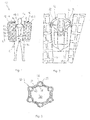
- the frame-web-structure comprises a frame of tube portions 28, wherein the tube portions 28 are made of flexible material suitable for being inflated, such as conventional textile materials used for conventional air bags.
- the tube portions 28 can be folded and collapsed in a deflated state and the interior of the tube portions 28 communicate with one another as well as with the inflation apparatus 20 to allow introduction of compressed air into the tube portions 28.
- the frame of tube portions 28 will then expand to a predetermined shape of a three dimensional grid or net that surrounds and encloses an interior 30 of the air bag 18-1.
- the overall shape of the first air bag 18-1 is substantially cylindrical having a cylinder axis C directed in a vertical direction or at a small angle relative to the vertical direction.
- the frame defining such shape may comprise tube portions 28 running in a circumferential direction of the cylinder, i. e. in the form of a plurality of horizontal circular rings 31, as well as substantially linear tube portions 32 extending substantially parallel to the cylinder axis C and thereby crossing the circular rings 31 to form knots 33.
- the circular rings 31 and the linear tube portions 32 are likewise interconnected with one another to be in gas communication with one another.
- the circular rings 31 and the linear tube portions 32 form a grid or net of generally cylindrical shape having a number of knots 33 at which the individual tube portions 28 are in gas communication with one another.
- Web portions 34 extend between adjacent parallel tube portions 28. Thus, the aperture regions of the grid or net are completely filled by the web portions 34.
- the web portions 34 may be formed of the same material as used for the tube portions 28.
- an integral layer may form an external wall 36 of at least one tube portion 28 as well as a web portion 34.
- an inner wall 38 of at least one tube portion 28 and an inner wall 40 of an adjacent web portion 34 are formed by an integral inner layer.
- the whole air bag 18-1 is formed by an outer layer of substantially cylindrical shape in the expanded state and an inner layer of substantially cylindrical shape in the expanded state, wherein the outer layer and the inner layer are fixed to one another in a gas-tight manner at the web portions 34, whereas they are separated at the tube portions 28.
- an air bag 18-1 is formed having a gas-tight shell, wherein the only gas communication between the interior 30 of the air bag 18-1 and the ambient air is allowed through a valve 42 arranged in the shell of the air bag 18-1, for example in an upper front part of the air bag 18-1.
- a valve 42 arranged in the shell of the air bag 18-1, for example in an upper front part of the air bag 18-1.
- the overall volume of gas introduced into the tube portions 28 is smaller than the volume of sucked-in ambient air in the interior 30 of the air bag 18-1 as can be seen in figure 3 .
- the gas volume to be provided by the inflation apparatus 20 can be kept at a minimum, whereas the air bag 18-1 can be provided with a sufficient overall gas volume and size to achieve sufficient floating and buoyancy during an avalanche accident.
- Valve 42 may preferably be provided in an upper part of the first air bag 18-1, in particular in an upper front portion of the air bag 18-1 facing the head of the user. Furthermore, valve 42 is preferably adapted to open and release air from the interior 30 of the first air bag 18-1 at some point in time after the inflation of the air bag 18-1. As a result, when the user gets packed under the snow, air from the interior 30 of air bag 18-1 can be blown towards the head of the user to provide breathing air.
- the interior 30 of air bag 18-1 is preferably only filled by ambient air such that it can be fully used as breathing air for the user, whereas the gas provided by a gas generator of the inflation apparatus 20 is only filled into the tube portions 28 of the frame structure and will not reach the interior 30 of the air bag 18-1.
- a gas optimized for the performance of the inflation apparatus 20 for example a carbon dioxide containing gas, may be used.
- the third air bag 18-3 may further have a valve 44 which is closed upon inflation of the third air bag 18-3 and which opens after a predetermined time after the activation of the air bag system such as to release gas from the interior of the third air bag 18-3. Since the interior of the third air bag 18-3 is inflated by compressed gas from the inflation apparatus 20, it is preferable to provide the valve 44 at a bottom part of the third air bag 18-3 such as to face away from the head of the user. In such configuration a gas may be used for inflating the air bags which is not optimized for breathing but is rather optimized for the operation of the inflation apparatus 20.
- the second air bag 18-2 can be configured in the same way as the first air bag 18-1.
- the third air bag 18-3 could be configured in the same way as the first air bag 18-1, although a different configuration as described below is preferable.
- the third air bag 18-3 may have a flat configuration in the expanded state such that dimensions in the forward-backward direction of the third air bag 18-3 with respect to the user are smaller than the dimensions in vertical and lateral directions.
- the purpose of the third air bag 18-3 is to provide and ensure some space in the region of the user's torso to give the user some freedom to breath when packed under the snow.
- the overall volume of the third air bag 18-3 may be smaller than that of the first and second air bags 18-1 and 18-2, respectively, because the latter are supposed to provide sufficient buoyancy. It is therefore possible to inflate the third air bag 18-3 completely by compressed gas from the inflation apparatus 20 and a frame structure as described above for the first air bag 18-1 can be dispensed with.
- the third air bag 18-3 can be manufactured by a simple one-layered air bag shell, for example having only one air bag chamber, wherein the interior of the third air bag 18-3 is to be inflated completely by the inflation apparatus 20.
- the third air bag 18-3 is provided at a back of the user and is thus included in the backpack-type carrying system 22.
- an air bag 18-4 at the chest of the user's torso which is connected to the inflation apparatus 20 or to its own inflation apparatus and is adapted to expand in the event of an emergency.
- Figure 4 illustrates additional preferred features of the avalanche rescue system according to the preferred embodiment which provide additional advantages but do not necessarily have to be provided to achieve the before-mentioned effects.
- the first and second air bags 18-1 and 18-2 are shown in solid lines in a normal, deflated or collapsed state
- the second air bag 18-2 is - for illustrative purposes - again shown in solid lines in the inflated or expanded state denoted with (18-2).
- the third and fourth air bags 18-3, 18-4 are shown in dot lines in an expanded state, wherein one of the third and fourth air bags 18-3 and 18-4 may be provided or both of the air bags 18-3 and 18-4 may be provided as desired.
- the third air bag 18-3 and the fourth air bag 18-4 are additionally illustrated in figure 4 in solid lines in a normal state (deflated and collapse state).
- a rear part of the backpack-type carrying system 12 may be formed by a rigid shell 46, which covers substantially the whole area of the user's back or at least a major part of the user's back.
- the rigid shell 46 may provide further mechanical protection of the user's back.
- the first and second air bags 18-1, 18-2, in a collapsed state are attached to a rear side of the rigid shell 46, i. e. the rigid shell 46 may be arranged between the air bags 18-1 and 18-2 and the user. This allows to protect and mechanically shield the back of the user against shocks emerging upon inflation of the air bags 18-1 and 18-2.
- the air bags 18-1 and 18-2 may be disposed in respective depressions 48-1 and 48-2 disposed on rear lateral sides of the rigid shell 46.
- the left or first air bag 18-1 may be disposed in a left depression 48-1
- the right or second air bag 18-2 may be disposed in a right depression 48-2 of the rigid shell 46.
- This arrangement allows not only a stable and reliable fixation of the air bags 18-1, 18-2, but also assists proper inflation of the air bags 18-1, 18-2 since the depressions 48-1, 48-2 will guide the air bag expansion towards defined directions to the rear left and the rear right, respectively.
- an avalanche probe 50 and an avalanche shovel 52 are preferably integrated into the carrying system 12, in particular inside a bag of the backpack-type carrying system 12 between the rigid shell 46 and a front part 54 of the carrying system 12 which is carried directly at the user's back by means of the belts 22, 24 and 26. Furthermore, the inflation apparatus 20 and maybe the third air bag 18-3 are also integrated in such bag.
- the avalanche rescue system In the event of an emergency, in particular an avalanche accident, the avalanche rescue system is activated by a manual operation of the user or automatically by a sensor system that detects such event (for example by virtue of a noise sensor or an acceleration sensor). Thereupon, the inflation apparatus 20 starts to fill compressed gas from a gas generator or a gas tank, preferably a compressed CO 2 tank, into the tube portions 28 of the first and second air bags 18-1 and 18-2 as well as into the interior of the third air bag 18-3 such that the frame structures of the first and second air bags 18-1, 18-2 and the the third air bag 18-3 expand.
- a gas generator or a gas tank preferably a compressed CO 2 tank
- valve 42 blocks or restricts the discharge of ambient air from the interior 30 such that the air bags 18-1, 18-2 keep their expanded shape even under the influence of external pressure from the snow.
- the user is able to float over the snow or at least to stay in higher regions of the snow.
- the three air bags 18-1, 18-2 and 18-3 are still inflated due to the operation of the valves 42 and 44. Only after some time, for example after several minutes, the valves 42 and 44 will open to allow some deflation of the air bags. Air being discharged from the interior 30 of the first and second air bags 18-1 and 18-2 may reach the head of the user to assist breathing. Furthermore, opening the valve 44 of the third air bag 18-3 leads to a deflation of the third air bag 18-3 such as to provide space around the user's torso to assist breathing further.
- the gas discharged from the third air bag 18-3 is preferably expelled in a direction away from the user's head such as to allow some sort of gas suitable for the inflation apparatus 20 and not necessarily being breathable to be used as a filling gas for the third air bag 18-3.
- the gas produced by the inflation apparatus 20 may also be breathable gas and the valve 44 may then be arranged at a position facing the head of the user.
Claims (15)
- Système de sauvetage lors d'avalanches (10) comprenant un système de transport (12) adapté pour être transporté sur le torse d'un utilisateur, et
un module de coussin d'air (16) destiné à être transporté par le système de transport (12), ledit module de coussin d'air (16) ayant- un premier coussin d'air (18-1), un deuxième coussin d'air (18-2) et un troisième coussin d'air (18-3, 18-4), lesdits coussins d'air étant repliés dans un état normal et déployés dans un état activé,- un appareil de gonflage (20) étant relié aux coussins d'air pour fournir du gaz comprimé aux coussins d'air pour gonfler et déployer les coussins d'air,dans lequel le premier coussin d'air (18-1) est adapté pour se déployer au niveau d'un premier côté latéral du torse de l'utilisateur, le deuxième coussin d'air (18-2) est adapté pour se déployer au niveau d'un deuxième côté latéral du torse de l'utilisateur et le troisième coussin d'air (18-3, 18-4) est adapté pour se déployer devant une poitrine ou derrière un dos du torse de l'utilisateur. - Système de sauvetage lors d'avalanches (10) selon la revendication 1, caractérisé en ce qu'à l'état déployé, le troisième coussin d'air (18-3) s'étend sur sensiblement toute la zone de la poitrine ou du dos du torse de l'utilisateur et chacun des premier et deuxième coussins d'air (18-1, 18-2) a un volume intérieur supérieur à celui du troisième coussin d'air (18-3).
- Système de sauvetage lors d'avalanches (10) selon la revendication 1 ou 2, caractérisé en ce que le système de transport (12) est un sac à dos et le module de coussin d'air (16) est relié de manière détachable au sac à dos de sorte que les premier et deuxième coussins d'air (18-1, 18-2), à l'état activé, se déploient au niveau de côtés latéralement opposés du sac à dos.
- Système de sauvetage lors d'avalanches (10) selon au moins une des revendications précédentes, caractérisé en ce que le système de transport (12) est un sac à dos et le sac à dos comprend en outre une plaque de protection rigide (46) s'étendant à travers au moins une moitié du dos de l'utilisateur et qui est fournie de préférence au niveau d'un côté arrière du sac à dos ou forme le côté arrière du sac à dos.
- Système de sauvetage lors d'avalanches (10) selon la revendication 4, caractérisé en ce que le troisième coussin d'air (18-3) est disposé entre le dos du torse de l'utilisateur et la plaque de protection (46), tandis que la plaque de protection (46) est disposée entre le dos du torse de l'utilisateur et les premier et deuxième coussins d'air (18-1, 18-2) à l'état normal.
- Système de sauvetage lors d'avalanches (10) selon au moins une des revendications précédentes, caractérisé en ce qu'au moins les premier et deuxième coussins d'air (18-1, 18-2) comprennent chacun un cadre déployable, ledit cadre étant composé d'une pluralité de portions de tube (28),
dans lequel l'intérieur des portions de tube (28) sont reliés l'un à l'autre et à l'appareil de gonflage (20) pour permettre la communication de gaz entre eux de façon à déployer le cadre par introduction de gaz comprimé de l'appareil de gonflage (20) dans les portions de tube (28),
dans lequel les parois externes (36) des portions de tube (28) sont reliées l'une à l'autre par des portions de tissu (34), de sorte que le cadre et les portions de tissu (34), dans un état normal, sont pliées et repliées, tandis que, dans un état déployé, le cadre et les portions de tissu (34) définissent ensemble une paroi de coussin d'air enfermant un intérieur de coussin d'air (30), dans lequel ledit intérieur de coussin d'air (30) a un volume supérieur à un volume total de l'intérieur des portions de tube (28). - Système de sauvetage lors d'avalanches (10) selon la revendication 6, caractérisé en ce que les portions de tube (28) et l'appareil de gonflage (20) sont hermétiquement scellés par rapport à l'intérieur de coussin d'air (30) et par rapport à l'ambiance externe du système de sauvetage lors d'avalanches (10).
- Système de sauvetage lors d'avalanches (10) selon la revendication 6 ou la revendication 7,
caractérisé en ce que l'intérieur des portions de tube (28) est relié à l'intérieur de coussin d'air (30) par au moins une valve. - Système de sauvetage lors d'avalanches (10) selon au moins une des revendications précédentes, caractérisé en ce que chacun d'au moins les premier et deuxième coussins d'air (18-1, 18-2) comprend une valve (42) pour commander un passage d'air entre l'intérieur (30) et l'extérieur du coussin d'air (18-1, 18-2), ladite valve (42) étant adaptée pour être ouverte pendant le déploiement du coussin d'air pour permettre à l'air ambiant d'entrer à l'intérieur (30) du coussin d'air et restreindre l'évacuation d'air de l'intérieur (30) du coussin d'air pour au moins un temps prédéterminé après l'activation du coussin d'air.
- Système de sauvetage lors d'avalanches (10) selon la revendication 9, caractérisé en ce que la valve (42) est adaptée pour permettre ou augmenter l'évacuation d'air de l'intérieur (30) du coussin d'air (18-1, 18-2) à un temps prédéterminé après l'activation du coussin d'air, dans lequel la valve (42) est disposée de préférence dans une portion du premier ou deuxième coussin d'air (18-1, 18-2) faisant face à la tête de l'utilisateur transportant le module de coussin d'air (16).
- Système de sauvetage lors d'avalanches (10) selon l'une quelconque des revendications précédentes, caractérisé en ce qu'au moins une portion de tissu (34, 40) du premier et/ou deuxième coussin d'air (18-1, 18-2) comprend des micro-trous, la dimension des micro-trous étant adaptée pour permettre l'évacuation d'air de l'intérieur (30) du coussin d'air (18-1, 18-2) dans une période de temps prédéterminée après l'activation du coussin d'air.
- Système de sauvetage lors d'avalanches (10) selon au moins une des revendications précédentes, caractérisé en ce que, à l'état déployé, l'intérieur de coussin d'air de chacun d'au moins les premier et deuxième coussins d'air (18-1, 18-2) est rempli principalement ou exclusivement d'air ambiant.
- Système de sauvetage lors d'avalanches (10) selon au moins une des revendications précédentes, caractérisé en ce que l'intérieur du troisième coussin d'air (18-3, 18-4) est relié à l'appareil de gonflage (20), de sorte que, à l'état déployé, l'intérieur du troisième coussin d'air (18-3, 18-4) est sensiblement entièrement rempli de gaz produit par l'appareil de gonflage (20).
- Système de sauvetage lors d'avalanches (10) selon au moins une des revendications précédentes, caractérisé en ce que le troisième coussin d'air (18-3, 18-4) comprend une valve (44) adaptée pour permettre ou augmenter l'évacuation de gaz de l'intérieur du troisième coussin d'air (18-3, 18-4) à un temps prédéterminé après l'activation du troisième coussin d'air, dans lequel la valve est disposée de préférence dans une portion du troisième coussin d'air tournée à l'opposé de la tête de l'utilisateur transportant le module de coussin d'air (16).
- Système de sauvetage lors d'avalanches (10) selon au moins une des revendications précédentes, caractérisé en ce que l'appareil de gonflage (20) comprend une source de gaz, de préférence une source de CO2.
Applications Claiming Priority (1)
| Application Number | Priority Date | Filing Date | Title |
|---|---|---|---|
| DE102015200364 | 2015-01-13 |
Publications (2)
| Publication Number | Publication Date |
|---|---|
| EP3045207A1 EP3045207A1 (fr) | 2016-07-20 |
| EP3045207B1 true EP3045207B1 (fr) | 2017-10-25 |
Family
ID=55080059
Family Applications (1)
| Application Number | Title | Priority Date | Filing Date |
|---|---|---|---|
| EP16150837.9A Active EP3045207B1 (fr) | 2015-01-13 | 2016-01-12 | Système d'airbag à avalanche comportant de multiples coussins d'air |
Country Status (1)
| Country | Link |
|---|---|
| EP (1) | EP3045207B1 (fr) |
Families Citing this family (4)
| Publication number | Priority date | Publication date | Assignee | Title |
|---|---|---|---|---|
| JP2019187797A (ja) * | 2018-04-25 | 2019-10-31 | Joyson Safety Systems Japan株式会社 | 背負い型エアバッグ装置及びエアバッグシステム |
| EP3812011A1 (fr) * | 2019-10-25 | 2021-04-28 | RAS Technology S.à.r.l. | Sac gonflable, sac à dos anti-avalanche et procédé de dégonflage d'un sac gonflable |
| DE102022113412A1 (de) * | 2022-05-27 | 2023-11-30 | ADVENATE GmbH | Lawinenrucksacksystem |
| WO2024042032A1 (fr) * | 2022-08-22 | 2024-02-29 | ADVENATE GmbH | Sac à dos de sécurité en cas d'avalanche |
Family Cites Families (4)
| Publication number | Priority date | Publication date | Assignee | Title |
|---|---|---|---|---|
| DE19502417C2 (de) * | 1995-01-26 | 1998-07-02 | Silvretta Sherpas Sportartikel | Schutz- und Rettungsvorrichtung |
| DE19703656A1 (de) | 1997-01-31 | 1998-08-06 | Peter Aschauer | Lawinenrettungssystem |
| KR101546120B1 (ko) * | 2009-06-05 | 2015-08-20 | 알파인스타스 리서치 에스알엘 | 모터사이클 운전자용 에어백 시스템 |
| WO2013174444A2 (fr) * | 2012-05-25 | 2013-11-28 | Pieps Gmbh | Système de sauvetage en avalanche |
-
2016
- 2016-01-12 EP EP16150837.9A patent/EP3045207B1/fr active Active
Non-Patent Citations (1)
| Title |
|---|
| None * |
Also Published As
| Publication number | Publication date |
|---|---|
| EP3045207A1 (fr) | 2016-07-20 |
Similar Documents
| Publication | Publication Date | Title |
|---|---|---|
| EP3045207B1 (fr) | Système d'airbag à avalanche comportant de multiples coussins d'air | |
| CN111494909B (zh) | 用于个人保护的模块化气囊系统 | |
| US5129107A (en) | Inflatable safety helmet, specially for motorcycling | |
| US6351854B1 (en) | Personal protection device | |
| KR101969195B1 (ko) | 독립적인 착용식 보호장치 및 보호복 조립체 | |
| US20140020158A1 (en) | Multilayer impact attenuating insert for headgear | |
| KR20070101839A (ko) | 목 및 등 보호 에어백 모듈 | |
| US10791785B2 (en) | Inflatable neck support for contact sports helmets | |
| RU2399389C1 (ru) | Устройство для аварийного спуска человека с высотного объекта (варианты) | |
| US8998667B2 (en) | Personal floatation device having selectively inflatable bladders | |
| WO2016148592A1 (fr) | Dispositif de sauvetage avec coussin de sécurité gonflable à avalanche | |
| US20160067123A1 (en) | System and method for preventing fall-related injuries | |
| US9371119B2 (en) | Personal flotation device having selectively inflatable bladders | |
| ES2316809T3 (es) | Dispositivo de seguridad tipo airbag. | |
| WO2013025848A1 (fr) | Appareil de protection amphibie | |
| ES2601843T3 (es) | Sistema de aterrizaje suave para una carga en caída libre, en particular para un vehículo, tal como un vehículo pilotado sin un conductor a bordo | |
| US20090233505A1 (en) | Armored inflatable boat cocoon | |
| KR100852213B1 (ko) | 벨트형 구명매트 | |
| WO2017126978A1 (fr) | Dispositif de flottaison pour nourrisson | |
| KR101888499B1 (ko) | 휴대용 수상 구명장비 | |
| CN214241247U (zh) | 可穿戴式救生装置 | |
| CA2763360A1 (fr) | Cocon pour bateau gonflable blinde | |
| CN114104302A (zh) | 可穿戴式救生装置 | |
| ES2603604A1 (es) | Amortiguador de caídas para personas | |
| WO2013186623A1 (fr) | Vêtement pourvu d'un coussin gonflable |
Legal Events
| Date | Code | Title | Description |
|---|---|---|---|
| PUAI | Public reference made under article 153(3) epc to a published international application that has entered the european phase |
Free format text: ORIGINAL CODE: 0009012 |
|
| AK | Designated contracting states |
Kind code of ref document: A1 Designated state(s): AL AT BE BG CH CY CZ DE DK EE ES FI FR GB GR HR HU IE IS IT LI LT LU LV MC MK MT NL NO PL PT RO RS SE SI SK SM TR |
|
| AX | Request for extension of the european patent |
Extension state: BA ME |
|
| RIN1 | Information on inventor provided before grant (corrected) |
Inventor name: MADAU, STEFANO Inventor name: COLOMBO, FABIO Inventor name: RESCH, EGON |
|
| 17P | Request for examination filed |
Effective date: 20161121 |
|
| RBV | Designated contracting states (corrected) |
Designated state(s): AL AT BE BG CH CY CZ DE DK EE ES FI FR GB GR HR HU IE IS IT LI LT LU LV MC MK MT NL NO PL PT RO RS SE SI SK SM TR |
|
| GRAP | Despatch of communication of intention to grant a patent |
Free format text: ORIGINAL CODE: EPIDOSNIGR1 |
|
| INTG | Intention to grant announced |
Effective date: 20170504 |
|
| GRAS | Grant fee paid |
Free format text: ORIGINAL CODE: EPIDOSNIGR3 |
|
| GRAA | (expected) grant |
Free format text: ORIGINAL CODE: 0009210 |
|
| AK | Designated contracting states |
Kind code of ref document: B1 Designated state(s): AL AT BE BG CH CY CZ DE DK EE ES FI FR GB GR HR HU IE IS IT LI LT LU LV MC MK MT NL NO PL PT RO RS SE SI SK SM TR |
|
| REG | Reference to a national code |
Ref country code: GB Ref legal event code: FG4D |
|
| REG | Reference to a national code |
Ref country code: CH Ref legal event code: EP |
|
| REG | Reference to a national code |
Ref country code: AT Ref legal event code: REF Ref document number: 939391 Country of ref document: AT Kind code of ref document: T Effective date: 20171115 |
|
| REG | Reference to a national code |
Ref country code: IE Ref legal event code: FG4D |
|
| REG | Reference to a national code |
Ref country code: DE Ref legal event code: R096 Ref document number: 602016000604 Country of ref document: DE |
|
| REG | Reference to a national code |
Ref country code: FR Ref legal event code: PLFP Year of fee payment: 3 |
|
| REG | Reference to a national code |
Ref country code: CH Ref legal event code: NV Representative=s name: E. BLUM AND CO. AG PATENT- UND MARKENANWAELTE , CH |
|
| REG | Reference to a national code |
Ref country code: NL Ref legal event code: MP Effective date: 20171025 |
|
| REG | Reference to a national code |
Ref country code: LT Ref legal event code: MG4D |
|
| PG25 | Lapsed in a contracting state [announced via postgrant information from national office to epo] |
Ref country code: NL Free format text: LAPSE BECAUSE OF FAILURE TO SUBMIT A TRANSLATION OF THE DESCRIPTION OR TO PAY THE FEE WITHIN THE PRESCRIBED TIME-LIMIT Effective date: 20171025 |
|
| PG25 | Lapsed in a contracting state [announced via postgrant information from national office to epo] |
Ref country code: NO Free format text: LAPSE BECAUSE OF FAILURE TO SUBMIT A TRANSLATION OF THE DESCRIPTION OR TO PAY THE FEE WITHIN THE PRESCRIBED TIME-LIMIT Effective date: 20180125 Ref country code: SE Free format text: LAPSE BECAUSE OF FAILURE TO SUBMIT A TRANSLATION OF THE DESCRIPTION OR TO PAY THE FEE WITHIN THE PRESCRIBED TIME-LIMIT Effective date: 20171025 Ref country code: ES Free format text: LAPSE BECAUSE OF FAILURE TO SUBMIT A TRANSLATION OF THE DESCRIPTION OR TO PAY THE FEE WITHIN THE PRESCRIBED TIME-LIMIT Effective date: 20171025 Ref country code: LT Free format text: LAPSE BECAUSE OF FAILURE TO SUBMIT A TRANSLATION OF THE DESCRIPTION OR TO PAY THE FEE WITHIN THE PRESCRIBED TIME-LIMIT Effective date: 20171025 Ref country code: FI Free format text: LAPSE BECAUSE OF FAILURE TO SUBMIT A TRANSLATION OF THE DESCRIPTION OR TO PAY THE FEE WITHIN THE PRESCRIBED TIME-LIMIT Effective date: 20171025 |
|
| PG25 | Lapsed in a contracting state [announced via postgrant information from national office to epo] |
Ref country code: HR Free format text: LAPSE BECAUSE OF FAILURE TO SUBMIT A TRANSLATION OF THE DESCRIPTION OR TO PAY THE FEE WITHIN THE PRESCRIBED TIME-LIMIT Effective date: 20171025 Ref country code: RS Free format text: LAPSE BECAUSE OF FAILURE TO SUBMIT A TRANSLATION OF THE DESCRIPTION OR TO PAY THE FEE WITHIN THE PRESCRIBED TIME-LIMIT Effective date: 20171025 Ref country code: IS Free format text: LAPSE BECAUSE OF FAILURE TO SUBMIT A TRANSLATION OF THE DESCRIPTION OR TO PAY THE FEE WITHIN THE PRESCRIBED TIME-LIMIT Effective date: 20180225 Ref country code: LV Free format text: LAPSE BECAUSE OF FAILURE TO SUBMIT A TRANSLATION OF THE DESCRIPTION OR TO PAY THE FEE WITHIN THE PRESCRIBED TIME-LIMIT Effective date: 20171025 Ref country code: BG Free format text: LAPSE BECAUSE OF FAILURE TO SUBMIT A TRANSLATION OF THE DESCRIPTION OR TO PAY THE FEE WITHIN THE PRESCRIBED TIME-LIMIT Effective date: 20180125 Ref country code: GR Free format text: LAPSE BECAUSE OF FAILURE TO SUBMIT A TRANSLATION OF THE DESCRIPTION OR TO PAY THE FEE WITHIN THE PRESCRIBED TIME-LIMIT Effective date: 20180126 |
|
| REG | Reference to a national code |
Ref country code: DE Ref legal event code: R097 Ref document number: 602016000604 Country of ref document: DE |
|
| PG25 | Lapsed in a contracting state [announced via postgrant information from national office to epo] |
Ref country code: CZ Free format text: LAPSE BECAUSE OF FAILURE TO SUBMIT A TRANSLATION OF THE DESCRIPTION OR TO PAY THE FEE WITHIN THE PRESCRIBED TIME-LIMIT Effective date: 20171025 Ref country code: CY Free format text: LAPSE BECAUSE OF FAILURE TO SUBMIT A TRANSLATION OF THE DESCRIPTION OR TO PAY THE FEE WITHIN THE PRESCRIBED TIME-LIMIT Effective date: 20171025 Ref country code: EE Free format text: LAPSE BECAUSE OF FAILURE TO SUBMIT A TRANSLATION OF THE DESCRIPTION OR TO PAY THE FEE WITHIN THE PRESCRIBED TIME-LIMIT Effective date: 20171025 Ref country code: SK Free format text: LAPSE BECAUSE OF FAILURE TO SUBMIT A TRANSLATION OF THE DESCRIPTION OR TO PAY THE FEE WITHIN THE PRESCRIBED TIME-LIMIT Effective date: 20171025 Ref country code: DK Free format text: LAPSE BECAUSE OF FAILURE TO SUBMIT A TRANSLATION OF THE DESCRIPTION OR TO PAY THE FEE WITHIN THE PRESCRIBED TIME-LIMIT Effective date: 20171025 |
|
| PG25 | Lapsed in a contracting state [announced via postgrant information from national office to epo] |
Ref country code: RO Free format text: LAPSE BECAUSE OF FAILURE TO SUBMIT A TRANSLATION OF THE DESCRIPTION OR TO PAY THE FEE WITHIN THE PRESCRIBED TIME-LIMIT Effective date: 20171025 Ref country code: SM Free format text: LAPSE BECAUSE OF FAILURE TO SUBMIT A TRANSLATION OF THE DESCRIPTION OR TO PAY THE FEE WITHIN THE PRESCRIBED TIME-LIMIT Effective date: 20171025 Ref country code: PL Free format text: LAPSE BECAUSE OF FAILURE TO SUBMIT A TRANSLATION OF THE DESCRIPTION OR TO PAY THE FEE WITHIN THE PRESCRIBED TIME-LIMIT Effective date: 20171025 |
|
| PLBE | No opposition filed within time limit |
Free format text: ORIGINAL CODE: 0009261 |
|
| STAA | Information on the status of an ep patent application or granted ep patent |
Free format text: STATUS: NO OPPOSITION FILED WITHIN TIME LIMIT |
|
| 26N | No opposition filed |
Effective date: 20180726 |
|
| PG25 | Lapsed in a contracting state [announced via postgrant information from national office to epo] |
Ref country code: LU Free format text: LAPSE BECAUSE OF NON-PAYMENT OF DUE FEES Effective date: 20180112 |
|
| REG | Reference to a national code |
Ref country code: IE Ref legal event code: MM4A |
|
| REG | Reference to a national code |
Ref country code: BE Ref legal event code: MM Effective date: 20180131 |
|
| PG25 | Lapsed in a contracting state [announced via postgrant information from national office to epo] |
Ref country code: BE Free format text: LAPSE BECAUSE OF NON-PAYMENT OF DUE FEES Effective date: 20180131 Ref country code: SI Free format text: LAPSE BECAUSE OF FAILURE TO SUBMIT A TRANSLATION OF THE DESCRIPTION OR TO PAY THE FEE WITHIN THE PRESCRIBED TIME-LIMIT Effective date: 20171025 |
|
| PG25 | Lapsed in a contracting state [announced via postgrant information from national office to epo] |
Ref country code: IE Free format text: LAPSE BECAUSE OF NON-PAYMENT OF DUE FEES Effective date: 20180112 |
|
| PG25 | Lapsed in a contracting state [announced via postgrant information from national office to epo] |
Ref country code: MC Free format text: LAPSE BECAUSE OF FAILURE TO SUBMIT A TRANSLATION OF THE DESCRIPTION OR TO PAY THE FEE WITHIN THE PRESCRIBED TIME-LIMIT Effective date: 20171025 |
|
| PG25 | Lapsed in a contracting state [announced via postgrant information from national office to epo] |
Ref country code: MT Free format text: LAPSE BECAUSE OF NON-PAYMENT OF DUE FEES Effective date: 20180112 |
|
| PG25 | Lapsed in a contracting state [announced via postgrant information from national office to epo] |
Ref country code: TR Free format text: LAPSE BECAUSE OF FAILURE TO SUBMIT A TRANSLATION OF THE DESCRIPTION OR TO PAY THE FEE WITHIN THE PRESCRIBED TIME-LIMIT Effective date: 20171025 |
|
| PG25 | Lapsed in a contracting state [announced via postgrant information from national office to epo] |
Ref country code: PT Free format text: LAPSE BECAUSE OF FAILURE TO SUBMIT A TRANSLATION OF THE DESCRIPTION OR TO PAY THE FEE WITHIN THE PRESCRIBED TIME-LIMIT Effective date: 20171025 |
|
| PG25 | Lapsed in a contracting state [announced via postgrant information from national office to epo] |
Ref country code: MK Free format text: LAPSE BECAUSE OF NON-PAYMENT OF DUE FEES Effective date: 20171025 Ref country code: HU Free format text: LAPSE BECAUSE OF FAILURE TO SUBMIT A TRANSLATION OF THE DESCRIPTION OR TO PAY THE FEE WITHIN THE PRESCRIBED TIME-LIMIT; INVALID AB INITIO Effective date: 20160112 |
|
| PG25 | Lapsed in a contracting state [announced via postgrant information from national office to epo] |
Ref country code: AL Free format text: LAPSE BECAUSE OF FAILURE TO SUBMIT A TRANSLATION OF THE DESCRIPTION OR TO PAY THE FEE WITHIN THE PRESCRIBED TIME-LIMIT Effective date: 20171025 |
|
| GBPC | Gb: european patent ceased through non-payment of renewal fee |
Effective date: 20200112 |
|
| PG25 | Lapsed in a contracting state [announced via postgrant information from national office to epo] |
Ref country code: GB Free format text: LAPSE BECAUSE OF NON-PAYMENT OF DUE FEES Effective date: 20200112 |
|
| REG | Reference to a national code |
Ref country code: AT Ref legal event code: UEP Ref document number: 939391 Country of ref document: AT Kind code of ref document: T Effective date: 20171025 |
|
| PGFP | Annual fee paid to national office [announced via postgrant information from national office to epo] |
Ref country code: FR Payment date: 20230124 Year of fee payment: 8 Ref country code: CH Payment date: 20230111 Year of fee payment: 8 Ref country code: AT Payment date: 20230120 Year of fee payment: 8 |
|
| PGFP | Annual fee paid to national office [announced via postgrant information from national office to epo] |
Ref country code: IT Payment date: 20230120 Year of fee payment: 8 Ref country code: DE Payment date: 20221228 Year of fee payment: 8 |
|
| P01 | Opt-out of the competence of the unified patent court (upc) registered |
Effective date: 20230510 |