EP3045094A1 - Sanitary tub assembly and method for installing a sanitary tub - Google Patents
Sanitary tub assembly and method for installing a sanitary tub Download PDFInfo
- Publication number
- EP3045094A1 EP3045094A1 EP16150607.6A EP16150607A EP3045094A1 EP 3045094 A1 EP3045094 A1 EP 3045094A1 EP 16150607 A EP16150607 A EP 16150607A EP 3045094 A1 EP3045094 A1 EP 3045094A1
- Authority
- EP
- European Patent Office
- Prior art keywords
- sanitary tub
- tub
- channel
- sealing material
- sanitary
- Prior art date
- Legal status (The legal status is an assumption and is not a legal conclusion. Google has not performed a legal analysis and makes no representation as to the accuracy of the status listed.)
- Granted
Links
Images


Classifications
-
- A—HUMAN NECESSITIES
- A47—FURNITURE; DOMESTIC ARTICLES OR APPLIANCES; COFFEE MILLS; SPICE MILLS; SUCTION CLEANERS IN GENERAL
- A47K—SANITARY EQUIPMENT NOT OTHERWISE PROVIDED FOR; TOILET ACCESSORIES
- A47K3/00—Baths; Douches; Appurtenances therefor
- A47K3/008—Sealing between wall and bathtub or shower tray
-
- A—HUMAN NECESSITIES
- A47—FURNITURE; DOMESTIC ARTICLES OR APPLIANCES; COFFEE MILLS; SPICE MILLS; SUCTION CLEANERS IN GENERAL
- A47K—SANITARY EQUIPMENT NOT OTHERWISE PROVIDED FOR; TOILET ACCESSORIES
- A47K3/00—Baths; Douches; Appurtenances therefor
- A47K3/28—Showers or bathing douches
- A47K3/40—Pans or trays
- A47K3/405—Pans or trays flush with the surrounding floor, e.g. for easy access
Definitions
- the present invention relates to a sanitary tub arrangement with a sanitary tub from a tub body, which is inserted with a downwardly angled from an upper edge of the tub in the direction of a side edge of the tub body in an upwardly open channel, in which a sanitary tub against the gutter sealing sealing material located.
- the invention also provides a method for installing a sanitary tub in a receiving space.
- the invention relates in particular to sanitary tubs with a tub body made of a layer material.
- sealing tapes are used in practice, which are attached to the sanitary tub and on the other hand, an adjacent wall or floor surface.
- Corresponding sealing tapes are made DE 299 05 152 U1 .
- DE 10 2014 102 045 A1 and DE 20 2006 010 243 U1 known, according to the DE 20 2006 010 243 U1 the sealing tape together with a support frame forms a channel in which a sealing strip rests against a lower edge of the sanitary tub.
- a sanitary tub arrangement with the features of the preamble of claim 1 is known from GB 2 323 278 A known, wherein the sealing material is first inserted into the upwardly open channel before a lower edge of the sanitary tub is placed on the sealing material.
- the present invention has the object, especially in a long-term use of the sanitary tub assembly to further increase the safety of the seal and to allow easy assembly during assembly.
- the object of the invention and solution of the problem are a sanitary tub arrangement according to claim 1 and method for installing a sanitary tub according to claim 14 and 15.
- the invention provides that in the channel on at least part of a circumference of the sanitary tub, the side edge of the tub body is completely embedded in the sealing material.
- the tub body is formed from a layer material, wherein the side edge of the layer material is completely embedded in the sealing material.
- the present sanitary tub arrangement is then initially of a configuration in which below the laterally angled down portion of the layer material, a channel is arranged, which receives the sanitary tub - at least on a part of its circumference -.
- a sealing tape can for example also be embedded in the sealing material in order to achieve a reliable and permanent seal.
- the side edge of the tub body or of the layer material is completely embedded in the sealing material, in particular cast, so that the sealing material not only on an end face of the side edge, but also on both sides laterally to such an end face and in particular in an upper region of the Surrounding sealing material.
- the layer material, starting from the side edge is embedded in the sealing material over a length of at least 5 mm, preferably at least 10 mm or more.
- the sealing material can also reduce the risk of such deformation per se depending on the strength. Since the sealing material also extends above the side edge, the sanitary tub can not be easily raised relative to the channel. Even with a lifting of the sanitary tub with respect to the channel, the sealing material is retained because it engages around the side edge on three sides.
- a sealing material must be used in the context of the invention, which is sufficiently fluid to embed the side edge during assembly can.
- the sanitary tub is formed of a layer material.
- a layer material in the context of the invention in particular to a sanitary tub formed plates from Sanitäracryl and steel enamel understood.
- the layer material usually has a layer thickness of less than 10 mm, in particular less than 5 mm.
- the typical thickness of steel enamel is usually between 1.5 mm and 4 mm.
- a preferred embodiment of the invention adjoins the downwardly angled portion of the layer material at a lower edge with the side edge.
- the side edge In the context of such a configuration is preferably provided that not only the side edge itself, but also the lower edge is completely embedded in the sealing material.
- the sanitary tub is then reliably held securely over the entire length of the lower edge and sealed.
- the flowable and preferably pourable sealing material is in the described embodiment during assembly in a position not only to enclose the side edge, but also to cover the top of the lower edge.
- the layer material is wetted by the sealing material, whereby an intimate adhesive bond can also arise.
- the sealing material must be durable be waterproof and should also have as much as possible a certain resistance to various chemicals such as detergents.
- sealing materials come into consideration, which are cured in the assembled state to a solid or which are permanently liquid, in particular viscous.
- the sealing material may be formed on a polymer basis, such a sealing material preferably having permanently elastic properties in order to be able to absorb without deformation of the sanitary tub and / or an adjacent building structure without breaking.
- Suitable sealing materials are, for example, hardening resins, silicones or the like. Such materials may be chemically cured by a mixture of various components (two-component resin) or else alone, for example by contact with air, although, as described above, even after curing, there is some elasticity.
- Various chemically curing adhesives are suitable in the context of the invention as a sealing material, initially a low viscosity is advantageous during assembly, so that the sealing material can initially distribute evenly.
- sealing materials are also possible within the scope of the invention.
- a physical hardening is present, for example, when the sealing material solidifies during assembly by cooling or evaporation of a solvent (eg alcohol or water). So it is conceivable, for example, to liquefy a plastic by heating and then bring in the manner described in the groove, which then embedded in the liquid state, the side edge becomes.
- a solvent eg alcohol or water
- viscous oils, bitumen or a non-water-soluble gel may be considered for this purpose.
- the dynamic viscosity ⁇ at 20 ° C. is preferably between 1 and 1000 Pa ⁇ s (pascal second), in particular between 10 and 100 Pa ⁇ s.
- the sealing material according to a preferred embodiment of the invention is relatively soft.
- the Shore hardness determined according to DIN EN ISO 868: 2003 is preferably between 20 and 85 Shore A, particularly preferably between 30 and 60 Shore A, the Shore hardness measurement method being based on the limited retention time of 15 seconds when determining the penetration depth Not only for solids, but also for highly viscous liquids can be used. In any case, the transition between a highly viscous liquid and a solid is not unique and is not relevant to the invention.
- the downwardly angled section is arranged in a groove, which can be easily filled during assembly with the initially flowable sealing material.
- the channel may for example be formed from a plastic, a composite profile or a metal profile, wherein such a profile may also be part of a sanitary tub supporting support structure.
- Suitable profiles are for example from the DE 10 2009 037 904 B3 known, wherein arranged on such profiles and feet of the support structure can be.
- a composite material for example, mixtures of reinforcing materials with thermoplastic or thermosetting plastics (resins) into consideration.
- a channel can also be formed by a flexible, watertight material strip, for example a sealing strip known from the prior art.
- a sealing band can be fastened to an underside of the layer material in the region of the upper edge of the tub and then guided outwards around the downwardly angled section of the layer material, whereby the channel shape described forms.
- the channel described can in principle also be provided in a tray carrier made of foam (for example Styropor®), hard foam, wood or in a comparable load-bearing construction. Furthermore, it is also possible to use a kind of film instead of a waterproof material strip, which either runs completely below the sanitary pan or is arranged as a kind of frame below the ball edge.
- foam for example Styropor®
- hard foam for example Styropor®
- wood for example Styropor®
- a kind of film instead of a waterproof material strip, which either runs completely below the sanitary pan or is arranged as a kind of frame below the ball edge.
- a part of the channel of a rigid profile and another part of the channel can be formed from a flexible, waterproof material strip.
- a sealing tape with pour in the sealing material whereby the sealing strip is fixed particularly reliably and firmly.
- the channel may be sealed in the region of the upper edge of the tub against an underside of the layer material. As a result, it can be prevented during assembly that the sealing material overflows inwards over the channel.
- an internal seal can alternatively be dispensed with.
- installation situations are conceivable in which an overflow can be tolerated inside, while an overflow of the sealing material in the outer region of the channel is disadvantageous, because then the sealing material may need to be removed, for example, to apply a silicone joint can. If, in this context, the sealing material from the channel can overflow inwards, a corresponding filling level of the sealing material in the channel can not be exceeded.
- parts of the channel can be designed with fillers such as foam or the like, but it should still be ensured that the free side edge of the layer material is embedded in the sealing material, which usually results in an adhesive connection.
- the invention also provides a method for installing a sanitary tub in a receiving space of a building construction having at least one wall or floor surface, the sanitary tub being formed from a layer material, in particular sanitary acrylic or steel enamel, and the layer material starting from an upper tub rim Direction of a side edge of the layer material angled downwards Section, wherein an upwardly open channel is disposed on at least one edge of the receiving space, wherein a sealing material is introduced into the channel and wherein the sanitary tub is inserted with the downwardly angled portion in the channel and connected to the sealing material.
- the invention provides that a flowable sealing material is introduced into the channel and the sanitary tub is inserted with the downwardly angled portion in the channel such that at least part of a circumference of the sanitary tub, the flowable sealing material flows around the side edge and thereby fully embeds.
- the flowable sealing material may be such that it also has a constant viscosity at a constant ambient temperature. Then, however, in terms of fluidity, it is necessary to select a material which, on the one hand, is thin enough to flow around the side edge and, on the other hand, can not be displaced or dissolved by water.
- the present invention also relates to a method for installing a sanitary tub in a receiving space of at least one wall or floor surface having building construction, the sanitary tub with a starting from an upper tub edge down angled portion is inserted into an upwardly open, at at least arranged an edge of the receptacle groove, and wherein a sealing material is introduced into the channel and connected to the sanitary tub, wherein according to the invention provided that the sealing material ⁇ having a first dynamic viscosity 1 less than 100 Pa ⁇ s, preferably s is introduced into the channel less than 10 Pa ⁇ wherein subsequently the sealing material cures chemically and / or physically and then either as a viscous liquid, a second dynamic viscosity ⁇ 2 which is at least ten times the first dynamic viscosity ⁇ 1 or forms a solid, which preferably has elastic properties.
- the sealing material cures in the context of the described variant, this may first be thin in its processing, resulting in a particularly easy handling. Due to the available materials, the first dynamic viscosity ⁇ 1 will be greater than 0.001 Pa ⁇ s (1 mPa ⁇ s). Preferably, the viscosity is greater than 10 mPa ⁇ s.
- the sealing material can be introduced before or after the correct arrangement of the sanitary tub in the receiving space in the gutter.
- the sanitary tub can be first accurately positioned and aligned without hurry.
- the sealing material may then be poured through a side gap between the sanitary tub and the adjacent wall or floor surface.
- the sealing material is first introduced into the channel before the sanitary tub is arranged in the correct position and inserted into the channel, there is the advantage that the channel is easily accessible from above when the sealing material is introduced.
- a hardening sealing material however, a limited processing time has to be considered.
- the height of the sealing material in the channel may for example be between 6 mm and 60 mm, preferably between 10 mm and 50 mm. If a thin-bodied sealing material is used at least during processing, an at least approximately equal height of the sealing material results at the angled section of the layer material below the upper edge of the tub on the one hand and on an outer side on the other hand, if no part of the channel is filled by an additional filling material.
- the weight of the sanitary tray and the liquid accumulated therein, and possibly also the weight of a user can be partially or completely across the channel and the sealing material to be supported, so that then in the context of such a configuration, the support structure can be simplified.
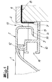
- Fig. 1 to 8 show in a section an outer region of a sanitary tub with an adjoining horizontal bottom surface.
- the Fig. 1 shows in a section of a sanitary tub arrangement with a sanitary tub 1 of a layer material, in particular steel enamel, which starting, with one of an upper tub edge 2 in the direction of a side edge 3 of the layer material a downwardly angled portion 4 has.
- the downwardly angled section 4 is inserted into an upwardly open channel 5.
- sealing material 6 which fully embeds the side edge 3 of the layer material. Since the sealing material 6 is thin at least during the arrangement of the sanitary tub 1, it extends to the downwardly unwound section 4 below the upper edge of the tub 2 on the one hand and on the outside of the sanitary tub 1 on the other hand over the same height or approximately the same height.
- a sealing tape 7 is embedded, which ensures a seal of the sanitary tub 1 against an adjacent bottom surface 8, which is covered in the illustrated embodiment by a cover material 9, such as tiles.
- the channel 5 is formed by a plastic or metal profile 10, which is also part of a sanitary tub 1 supporting support structure.
- a plastic or metal profile 10 which is also part of a sanitary tub 1 supporting support structure.
- an inwardly directed C-shaped groove 11 according to the DE 10 2009 037 094 B3 Feet are attached.
- the sanitary tub 1 is supported via a rubber profile 12 on a web of the plastic or metal profile 10. If the web of the plastic or metal profile 10 and the rubber profile 12 extend around the entire circumference of the sanitary tub 1, thereby the upwardly open channel 5 is sealed inwards. This also excludes that the channel 5 can overflow inwards if too much Sealant 6 is introduced.
- the sealing material 6 can be cast either before inserting the sanitary tub 1 into the channel 5 or subsequently through a lateral gap 13.
- a lower edge 14 with the side edge 3 at its end adjoins the downwardly angled section 4 of the layer material. Also, the entire lower edge 14 is embedded in the sealing material 6, so that there is a particularly reliable and durable seal. Even if the sanitary tub 1 is raised to a certain extent relative to the channel 5, the seal is maintained by the sealing material 6, especially if this is permanently elastic or liquid or viscous even in the illustrated assembled state.
- the sealing tape 7 is attached to the sanitary tub 1.
- the sealing tape 7 can first be fastened to the sanitary tub 1 before the sanitary tub 1 is then positioned in the channel 5 in the correct position.
- the sealing material 6 may already be in the channel 5.
- the sealing strip 7 can also be folded up first, in order then to be able to subsequently fill the sealing material 6 through the lateral gap 13 into the channel 5.
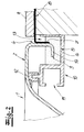
- the gutter 5 forming plastic or metal profile 10 is not part of a support structure, but is laterally attached to the bottom surface 8.
- the channel 5 can also be formed by a material other than a plastic or metal profile 10.
- materials such as composites, wood, foam or the like come into consideration.
- the channel can also be incorporated into a larger load-bearing structure, in which case the aforementioned materials may also be considered.
- the described embodiment results in an improved decoupling of the bottom surface 8 of the sanitary tub 1, resulting in a better sound insulation and horizontal displacements between the sanitary tub 1 and the bottom surface 8 can be more easily compensated.
- the channel 5 can also be formed by a flexible, waterproof material strip, for example the sealing tape 7 described above.
- the sealing strip 7 is to the side of a plastic or metal profile 10 'connected, which compared to the plastic or metal profile 10 of Fig. 1 has a simplified structure, so that the total manufacturing costs can be reduced.
- an elastic filling material 15 in the form of a foam strip is also partially arranged in the cross section of the channel 5.
- Foam strips can be provided in the circumferential direction continuously or only in sections.
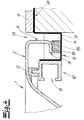
- the Fig. 5 shows as a further variant that the channel 5 can also be formed from the combination of a plastic or metal profile 10 "and a sealing strip 7.
- filling material 15 is disposed on the inside of the sanitary tub 1 below the upper edge of the tub 2.
- the Fig. 6 shows a further variant in which the channel 5 is formed by a sealing strip 7, wherein the sanitary tub 1 is held by a subsequent to the sealing strip 7 Schamstoffiki 16.
- a foam carrier 16 ' is provided, which also extends beyond the outer edge of the sanitary tub 1 addition, so that then the channel 5 is formed as an overhead groove in the foam carrier 16'.
- a sealing strip 7 can be used.
- the sealing tape 7 can optionally also be omitted if the foam 16' itself is watertight, for example has a waterproof surface coating or sealing.
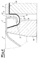
- the Fig. 8 shows, finally, that the channel 5 can also be formed by a first largely free-hanging sealing strip 7, in which case the sanitary tub 1 outside its outer edge can be received by a support structure, not shown. Furthermore, in the Fig. 8 illustrated that the sealing strip 7 may be mounted in the region of the upper edge of the tub at the bottom of the sanitary tub 1. Such an attachment is also in the other embodiments, for example in the embodiments according to the Fig. 4 and the Fig. 6 possible.
- a sealing tape 7 which extends at the edge of the sanitary tub.
- a continuous sealing strip can be used around the circumference.
- the channel can also be formed by pieces of the sealing strip 7.
- special prefabricated corner elements may be provided at corners of the sanitary tub 1, so that a sealing structure is formed around the entire circumference.
Abstract
Die Erfindung betrifft eine Sanitärwannenanordnung mit einer Sanitärwanne (1) aus einem Schichtmaterial, welche mit einem von einem oberen Wannenrand (2) in Richtung einer Seitenkante (3) des Schichtmaterials nach unten abgewinkelten Abschnitt (4) in eine nach oben offene Rinne (5) eingesetzt ist, in der sich ein die Sanitärwanne (1) gegen die Rinne (5) abdichtendes Dichtmaterial (6) befindet. Erfindungsgemäß ist die Seitenkante (3) in der Rinne (5) an zumindest einem Teil eines Umfangs der Sanitärwanne (1) vollständig in das Dichtmaterial (6) eingebettet. Gegenstand der Erfindung ist auch ein Verfahren zur Installation der Sanitärwanne (1) in einem Aufnahmeraum einer zumindest eine Wand- oder Bodenfläche (8) aufweisenden Gebäudekonstruktion, wobei das Dichtmaterial (6) zumindest während der Installation der Sanitärwanne (1) fließfähig ist.

Description
Die vorliegende Erfindung betrifft eine Sanitärwannenanordnung mit einer Sanitärwanne aus einem Wannenkörper, welches mit einem von einem oberen Wannenrand in Richtung einer Seitenkante des Wannenkörpers nach unten abgewinkelten Abschnitt in eine nach oben offene Rinne eingesetzt ist, in der sich ein die Sanitärwanne gegen die Rinne abdichtendes Dichtmaterial befindet. Gegenstand der Erfindung ist auch ein Verfahren zur Installation einer Sanitärwanne in einem Aufnahmeraum. Die Erfindung bezieht sich insbesondere auf Sanitärwannen mit einem Wannenkörper aus einem Schichtmaterial.The present invention relates to a sanitary tub arrangement with a sanitary tub from a tub body, which is inserted with a downwardly angled from an upper edge of the tub in the direction of a side edge of the tub body in an upwardly open channel, in which a sanitary tub against the gutter sealing sealing material located. The invention also provides a method for installing a sanitary tub in a receiving space. The invention relates in particular to sanitary tubs with a tub body made of a layer material.
Bei Sanitärwannen wie Duschwannen, Badewannen und Waschbecken ist auf eine gute Abdichtung gegenüber der umgebenden Gebäudekonstruktion zu achten. Es muss vermieden werden, dass Spritzwasser oder auch überlaufendes Wasser im Bereich der Sanitärwanne in die Gebäudekonstruktion eindringt und so zu erheblichen Schäden führen kann, welche zum Teil erst mit einer größeren Verzögerung festgestellt werden können.For sanitary tubs such as shower trays, bathtubs and wash basins, a good seal against the surrounding building structure must be ensured. It must be avoided that splash water or overflowing water in the area of the sanitary tub penetrates into the building structure and thus can lead to considerable damage, which can be determined in part only with a greater delay.
Um eine gute und zuverlässige Abdichtung zu erreichen, werden in der Praxis Dichtbänder eingesetzt, die an der Sanitärwanne und andererseits einer angrenzenden Wand- oder Bodenfläche befestigt werden. Entsprechende Dichtbänder sind aus
Eine Sanitärwannenanordnung mit den Merkmalen des Oberbegriffes des Patentanspruches 1 ist aus der
Bei dem langfristigen Einsatz einer Sanitärwanne ist zu berücksichtigen, dass gewisse Verformungen, wie beispielsweise ein Setzverhalten, einer Gebäudekonstruktion nicht ausgeschlossen werden können. Es besteht dann die Gefahr, dass durch entsprechende Bewegungen die Sanitärwanne von dem Dichtmaterial getrennt wird, wodurch dann entsprechend Undichtigkeiten entstehen können. Darüber hinaus muss das Dichtmaterial mit einer genau definierten Menge eingebracht werden, um eine zuverlässige Abdichtung der Sanitärwanne in der zugeordneten Rinne zu erreichen.In the long-term use of a sanitary tub, it must be taken into account that certain deformations, such as setting behavior, of a building construction can not be excluded. There is then the danger that the sanitary tub is separated from the sealing material by appropriate movements, which can then arise corresponding leaks. In addition, the sealing material must be introduced with a precisely defined amount in order to achieve a reliable seal of the sanitary tub in the associated channel.
Vor diesem Hintergrund liegt der vorliegenden Erfindung die Aufgabe zugrunde, gerade bei einem langfristigen Gebrauch der Sanitärwannenanordnung die Sicherheit der Abdichtung weiter zu erhöhen und bei der Montage eine leichte Handhabung zu ermöglichen.Against this background, the present invention has the object, especially in a long-term use of the sanitary tub assembly to further increase the safety of the seal and to allow easy assembly during assembly.
Gegenstand der Erfindung und Lösung der Aufgabe sind eine Sanitärwannenanordnung gemäß Patentanspruch 1 sowie Verfahren zur Installation einer Sanitärwanne gemäß Patentanspruch 14 und 15.The object of the invention and solution of the problem are a sanitary tub arrangement according to claim 1 and method for installing a sanitary tub according to
Ausgehend von einer Sanitärwannenanordnung mit dem eingangs beschriebenen Merkmal ist erfindungsgemäß vorgesehen, dass in der Rinne an zumindest einem Teil eines Umfangs der Sanitärwanne die Seitenkante des Wannenkörpers vollständig in das Dichtmaterial eingebettet ist.Based on a sanitary tub arrangement with the feature described above, the invention provides that in the channel on at least part of a circumference of the sanitary tub, the side edge of the tub body is completely embedded in the sealing material.
Bevorzugt ist der Wannenkörper aus einem Schichtmaterial gebildet, wobei die Seitenkante des Schichtmaterials vollständig in das Dichtmaterial eingebettet ist.Preferably, the tub body is formed from a layer material, wherein the side edge of the layer material is completely embedded in the sealing material.
Die vorliegende Sanitärwannenanordnung geht dann zunächst von einer Ausgestaltung aus, bei der unterhalb des seitlich nach unten abgewinkelten Abschnitts des Schichtmaterials eine Rinne angeordnet ist, welche die Sanitärwanne - zumindest an einem Teil ihres Umfangs - aufnimmt.The present sanitary tub arrangement is then initially of a configuration in which below the laterally angled down portion of the layer material, a channel is arranged, which receives the sanitary tub - at least on a part of its circumference -.
Die Sanitärwanne wird dann in diese Rinne eingesetzt und gegen diese Rinne abgedichtet, wobei unabhängig davon auch eine zusätzliche Abdichtung durch ein Dichtband oder dergleichen zweckmäßig ist. Ein solches Dichtband kann beispielsweise auch in das Dichtmaterial eingebettet sein, um eine zuverlässige und dauerhafte Abdichtung zu erreichen.The sanitary tub is then inserted into this channel and sealed against this channel, which is independent of an additional seal by a sealing tape or the like appropriate. Such a sealing tape can for example also be embedded in the sealing material in order to achieve a reliable and permanent seal.
Erfindungsgemäß ist die Seitenkante des Wannenkörpers bzw. des Schichtmaterials vollständig in das Dichtmaterial eingebettet, insbesondere eingegossen, so dass das Dichtmaterial nicht nur an einer Stirnfläche der Seitenkante, sondern auch an beiden Seiten seitlich zu einer solchen Stirnfläche und insbesondere auch in einem oberen Bereich von dem Dichtmaterial umgeben ist. Üblicherweise ist das Schichtmaterial ausgehend von der Seitenkante über eine Länge von zumindest 5 mm, bevorzugt zumindest 10 mm oder mehr in das Dichtmaterial eingebettet.According to the invention the side edge of the tub body or of the layer material is completely embedded in the sealing material, in particular cast, so that the sealing material not only on an end face of the side edge, but also on both sides laterally to such an end face and in particular in an upper region of the Surrounding sealing material. Usually, the layer material, starting from the side edge, is embedded in the sealing material over a length of at least 5 mm, preferably at least 10 mm or more.
Selbst bei einer Bewegung der Rinne gegenüber der Sanitärwanne kann eine sichere Abdichtung gewährleistet werden. Insbesondere kann das Dichtmaterial auch je nach Festigkeit die Gefahr einer solchen Verformung an sich reduzieren. Da sich das Dichtmaterial auch oberhalb der Seitenkante erstreckt, kann die Sanitärwanne gegenüber der Rinne nicht leicht angehoben werden. Selbst bei einem Anheben der Sanitärwanne gegenüber der Rinne bleibt das Dichtmaterial erhalten, weil es die Seitenkante an drei Seiten umgreift.Even with a movement of the channel relative to the sanitary tub, a secure seal can be ensured. In particular, the sealing material can also reduce the risk of such deformation per se depending on the strength. Since the sealing material also extends above the side edge, the sanitary tub can not be easily raised relative to the channel. Even with a lifting of the sanitary tub with respect to the channel, the sealing material is retained because it engages around the side edge on three sides.
Um die beschriebene Anordnung zu erreichen, muss im Rahmen der Erfindung ein Dichtmaterial eingesetzt werden, welches im ausreichenden Maße fließfähig ist, um bei der Montage die Seitenkante einbetten zu können.In order to achieve the described arrangement, a sealing material must be used in the context of the invention, which is sufficiently fluid to embed the side edge during assembly can.
Gemäß der beschriebenen erfindungsgemäßen Ausgestaltung ist die Sanitärwanne aus einem Schichtmaterial gebildet. Als Schichtmaterial werden im Rahmen der Erfindung insbesondere zu einer Sanitärwanne umgeformte Platten aus Sanitäracryl und Stahl-Email verstanden. Das Schichtmaterial weist üblicherweise eine Schichtdicke von weniger als 10 mm, insbesondere weniger als 5 mm auf. Die typische Dicke von Stahl-Email beträgt üblicherweise zwischen 1,5 mm und 4 mm.According to the described embodiment of the invention, the sanitary tub is formed of a layer material. As a layer material in the context of the invention in particular to a sanitary tub formed plates from Sanitäracryl and steel enamel understood. The layer material usually has a layer thickness of less than 10 mm, in particular less than 5 mm. The typical thickness of steel enamel is usually between 1.5 mm and 4 mm.
Gemäß einer bevorzugten Ausgestaltung der Erfindung schließt an den nach unten abgewinkelten Abschnitt des Schichtmaterials eine Unterkantung mit der Seitenkante an. Im Rahmen einer solchen Ausgestaltung ist vorzugsweise vorgesehen, dass nicht nur die Seitenkante an sich, sondern auch die Unterkantung vollständig in dem Dichtmaterial eingebettet ist. Die Sanitärwanne ist dann zuverlässig über die gesamte Länge der Unterkantung sicher gehalten und abgedichtet. Das fließfähige und vorzugsweise auch gießfähige Dichtmaterial ist im Rahmen der beschriebenen Ausführung bei der Montage in der Lage, nicht nur die Seitenkante zu umschließen, sondern auch die Oberseite der Unterkantung zu bedecken.According to a preferred embodiment of the invention adjoins the downwardly angled portion of the layer material at a lower edge with the side edge. In the context of such a configuration is preferably provided that not only the side edge itself, but also the lower edge is completely embedded in the sealing material. The sanitary tub is then reliably held securely over the entire length of the lower edge and sealed. The flowable and preferably pourable sealing material is in the described embodiment during assembly in a position not only to enclose the side edge, but also to cover the top of the lower edge.
Üblicherweise wird das Schichtmaterial von dem Dichtmaterial benetzt, wobei auch eine innige adhäsive Verbindung entstehen kann.Usually, the layer material is wetted by the sealing material, whereby an intimate adhesive bond can also arise.
Für die Ausgestaltung des Dichtmaterials ergeben sich im Rahmen der Erfindung verschiedene Möglichkeiten. Zunächst muss das Dichtmaterial dauerhaft wasserdicht sein und soll auch möglichst eine gewisse Beständigkeit gegen verschiedene Chemikalien wie beispielsweise Reinigungsmittel aufweisen.For the design of the sealing material, various possibilities arise within the scope of the invention. First, the sealing material must be durable be waterproof and should also have as much as possible a certain resistance to various chemicals such as detergents.
Davon ausgehend kommen Dichtmaterialien in Betracht, welche im montierten Zustand zu einem Festkörper ausgehärtet sind oder welche dauerhaft flüssig, insbesondere zähflüssig sind.On this basis, sealing materials come into consideration, which are cured in the assembled state to a solid or which are permanently liquid, in particular viscous.
Beispielsweise kann das Dichtmaterial auf Polymerbasis gebildet sein, wobei ein solches Dichtmaterial vorzugsweise dauerelastische Eigenschaften aufweist, um ohne zu brechen Verformungen der Sanitärwanne und/oder einer angrenzenden Gebäudekonstruktion aufnehmen zu können. Als Dichtmaterialien kommen beispielsweise aushärtende Harze, Silikone oder dergleichen in Betracht. Solche Materialien können durch eine Mischung verschiedener Komponenten (Zwei-Komponenten-Harz) oder auch alleine, beispielsweise durch den Kontakt mit Luft, chemisch aushärtend sein, wobei jedoch wie zuvor beschrieben auch nach dem Aushärten eine gewisse Elastizität vorhanden ist.For example, the sealing material may be formed on a polymer basis, such a sealing material preferably having permanently elastic properties in order to be able to absorb without deformation of the sanitary tub and / or an adjacent building structure without breaking. Suitable sealing materials are, for example, hardening resins, silicones or the like. Such materials may be chemically cured by a mixture of various components (two-component resin) or else alone, for example by contact with air, although, as described above, even after curing, there is some elasticity.
Verschiedene chemisch aushärtende Klebstoffe sind im Rahmen der Erfindung als Dichtmaterial geeignet, wobei zunächst bei der Montage eine geringe Viskosität von Vorteil ist, damit sich das Dichtmaterial zunächst besonders gleichmäßig verteilen kann.Various chemically curing adhesives are suitable in the context of the invention as a sealing material, initially a low viscosity is advantageous during assembly, so that the sealing material can initially distribute evenly.
Neben chemisch aushärtenden Materialien kommen im Rahmen der Erfindung auch physikalisch aushärtende Dichtmaterialien in Betracht. Eine physikalische Aushärtung liegt beispielsweise vor, wenn das Dichtmaterial bei der Montage durch eine Abkühlung oder ein Verdunsten eines Lösungsmittels (z. B. Alkohol oder Wasser) erstarrt. So ist es beispielsweise denkbar, einen Kunststoff durch ein Erwärmen zu verflüssigen und dann in der beschriebenen Weise in die Rinne einzubringen, wodurch dann im flüssigen Zustand die Seitenkante eingebettet wird. Zu diesem Zweck kommen beispielsweise zähflüssige Öle, Bitumen oder ein nicht wasserlösliches Gel in Betracht.In addition to chemically curing materials, physically hardening sealing materials are also possible within the scope of the invention. A physical hardening is present, for example, when the sealing material solidifies during assembly by cooling or evaporation of a solvent (eg alcohol or water). So it is conceivable, for example, to liquefy a plastic by heating and then bring in the manner described in the groove, which then embedded in the liquid state, the side edge becomes. For example, viscous oils, bitumen or a non-water-soluble gel may be considered for this purpose.
Bei einem nicht wasserlöslichen und dauerhaft zähflüssigen Dichtmaterial beträgt die dynamische Viskosität η bei 20 °C vorzugsweise zwischen 1 und 1000 Pa·s (Pascalsekunde) insbesondere zwischen 10 und 100 Pa·s.In the case of a non-water-soluble and permanently viscous sealing material, the dynamic viscosity η at 20 ° C. is preferably between 1 and 1000 Pa · s (pascal second), in particular between 10 and 100 Pa · s.
Wenn bei dem langfristigen Gebrauch der Sanitärwannenanordnung gewisse Verformungen auftreten, können Spannungen in einem dauerhaft zähflüssigen Dichtmaterial durch ein Fließen dieses Dichtmaterials verhindert werden.When certain deformations occur in the long-term use of the sanitary tub assembly, stresses in a permanently viscous sealing material can be prevented by flow of this sealing material.
Um auch bei der eingebauten Sanitärwannenanordnung in einem ausreichenden Maße beweglich zu sein, ist das Dichtmaterial gemäß einer bevorzugten Ausgestaltung der Erfindung relativ weich. So beträgt die gemäß DIN EN ISO 868:2003 bestimmte Shore-Härte vorzugsweise zwischen 20 und 85 Shore A, besonders bevorzugt zwischen 30 und 60 Shore A, wobei das Messverfahren der Shore-Härte aufgrund der begrenzten Haltezeit von 15 Sekunden bei der Bestimmung der Eindringtiefe nicht nur für Festkörper, sondern auch für hochviskose Flüssigkeiten eingesetzt werden kann. Ohnehin ist der Übergang zwischen einer hochviskosen Flüssigkeit und einem Festkörper im Einzelnen nicht eindeutig und auch im Rahmen der Erfindung nicht von Belang.In order to be able to move to a sufficient extent in the built-in sanitary tub arrangement, the sealing material according to a preferred embodiment of the invention is relatively soft. Thus, the Shore hardness determined according to DIN EN ISO 868: 2003 is preferably between 20 and 85 Shore A, particularly preferably between 30 and 60 Shore A, the Shore hardness measurement method being based on the limited retention time of 15 seconds when determining the penetration depth Not only for solids, but also for highly viscous liquids can be used. In any case, the transition between a highly viscous liquid and a solid is not unique and is not relevant to the invention.
Erfindungsgemäß ist der unten abgewinkelte Abschnitt in einer Rinne angeordnet, die bei der Montage leicht mit dem zunächst fließfähigen Dichtmaterial gefüllt werden kann. Die Rinne kann beispielsweise aus einem Kunststoff-, einem Verbundprofil oder einem Metallprofil gebildet werden, wobei ein solches Profil auch Bestandteil einer die Sanitärwanne tragenden Tragstruktur sein kann. Geeignete Profile sind beispielsweise aus der
Die vorliegende Erfindung ist jedoch nicht auf starre Rinnen aus einem Kunststoff- oder Metallprofil beschränkt. Alternativ kann eine Rinne auch von einem flexiblen, wasserdichten Materialstreifen gebildet werden, beispielsweise einem aus dem Stand der Technik bekannten Dichtband. Ein Dichtband kann im Bereich des oberen Wannenrandes an einer Unterseite des Schichtmaterials befestigt und dann um den nach unten abgewinkelten Abschnitt des Schichtmaterials nach außen geführt sein, wodurch sich die beschriebene Rinnenform bildet. Durch das zumindest teilweise Ausgießen dieser Rinne durch das Dichtmaterial unter Einbindung der freien Seitenkante wird eine besonders zuverlässige und dauerhafte Dichtstruktur erzeugt. Insbesondere kann das zunächst bei der Verarbeitung fließfähige und danach vorzugsweise zumindest noch dauerelastische Dichtmaterial auch zu einer verbesserten Schall- und Wärmedämmung der Sanitärwanne beitragen.However, the present invention is not limited to rigid gutters made of a plastic or metal profile. Alternatively, a channel can also be formed by a flexible, watertight material strip, for example a sealing strip known from the prior art. A sealing band can be fastened to an underside of the layer material in the region of the upper edge of the tub and then guided outwards around the downwardly angled section of the layer material, whereby the channel shape described forms. By at least partially pouring this channel through the sealing material with the inclusion of the free side edge a particularly reliable and durable sealing structure is produced. In particular, the initially flowable in the processing and then preferably at least still permanently elastic sealing material can also contribute to improved sound and heat insulation of the sanitary tub.
Die beschriebene Rinne kann grundsätzlich auch in einem Wannenträger aus Schaumstoff (beispielsweise Styropor ®), Hartschaum, Holz oder bei einer vergleichbaren tragenden Konstruktion vorgesehen sein. Des Weiteren ist es auch möglich, anstelle eines wasserdichten Materialstreifens eine Art Folie einzusetzen, welche entweder vollständig unterhalb der Sanitärwanne verläuft oder als eine Art Rahmen unterhalb des Ballenrandes angeordnet ist.The channel described can in principle also be provided in a tray carrier made of foam (for example Styropor®), hard foam, wood or in a comparable load-bearing construction. Furthermore, it is also possible to use a kind of film instead of a waterproof material strip, which either runs completely below the sanitary pan or is arranged as a kind of frame below the ball edge.
Schließlich kann auch ein Teil der Rinne aus einem starren Profil und ein anderer Teil der Rinne aus einem flexiblen, wasserdichten Materialstreifen gebildet werden. Insbesondere kann es zweckmäßig sein, ein Dichtband mit in das Dichtmaterial einzugießen, wodurch das Dichtband besonders zuverlässig und fest fixiert wird.Finally, a part of the channel of a rigid profile and another part of the channel can be formed from a flexible, waterproof material strip. In particular, it may be appropriate to use a sealing tape with pour in the sealing material, whereby the sealing strip is fixed particularly reliably and firmly.
Unabhängig von der konkreten Ausgestaltung der Rinne kann diese im Bereich des oberen Wannenrandes gegen eine Unterseite des Schichtmaterials abgedichtet sein. Dadurch kann bei der Montage verhindert werden, dass das Dichtmaterial nach innen über die Rinne überläuft. Je nach konkreten Anforderungen hinsichtlich der Einbausituation kann alternativ aber auf eine Abdichtung nach innen verzichtet werden. So sind beispielsweise auch Einbausituationen denkbar, bei denen ein Überlaufen nach innen durchaus hingenommen werden kann, während ein Überlaufen des Dichtmaterials im äußeren Bereich der Rinne nachteilig ist, weil dann das Dichtmaterial ggf. entfernt werden muss, um beispielsweise eine Silikonfuge aufbringen zu können. Wenn in diesem Zusammenhang das Dichtmaterial aus der Rinne nach innen überlaufen kann, kann ein entsprechender Füllstand des Dichtmaterials in der Rinne nicht überschritten werden.Regardless of the specific design of the channel, it may be sealed in the region of the upper edge of the tub against an underside of the layer material. As a result, it can be prevented during assembly that the sealing material overflows inwards over the channel. Depending on the specific requirements with regard to the installation situation, however, an internal seal can alternatively be dispensed with. Thus, for example, installation situations are conceivable in which an overflow can be tolerated inside, while an overflow of the sealing material in the outer region of the channel is disadvantageous, because then the sealing material may need to be removed, for example, to apply a silicone joint can. If, in this context, the sealing material from the channel can overflow inwards, a corresponding filling level of the sealing material in the channel can not be exceeded.
Um die Menge des eingesetzten Dichtmaterials zu verringern, können Teile der Rinne mit Füllstoffen wie Schaumstoff oder dergleichen ausgelegt sein, wobei aber weiterhin gewährleistet werden soll, dass die freie Seitenkante des Schichtmaterials in das Dichtmaterial eingebettet ist, wodurch sich üblicherweise eine adhäsive Verbindung ergibt.In order to reduce the amount of sealing material used, parts of the channel can be designed with fillers such as foam or the like, but it should still be ensured that the free side edge of the layer material is embedded in the sealing material, which usually results in an adhesive connection.
Gegenstand der Erfindung ist auch ein Verfahren zur Installation einer Sanitärwanne in einem Aufnahmeraum einer zumindest eine Wand- oder Bodenfläche aufweisenden Gebäudekonstruktion, wobei die Sanitärwanne aus einem Schichtmaterial, also insbesondere Sanitäracryl oder Stahl-Email, gebildet ist und das Schichtmaterial ausgehend von einem oberen Wannenrand in Richtung einer Seitenkante des Schichtmaterials einen nach unten abgewinkelten Abschnitt aufweist, wobei eine nach oben offene Rinne an zumindest einem Rand des Aufnahmeraums angeordnet wird, wobei ein Dichtmaterial in die Rinne eingebracht wird und wobei die Sanitärwanne mit dem nach unten abgewinkelten Abschnitt in die Rinne eingesetzt und mit dem Dichtmaterial verbunden wird. Davon ausgehend ist erfindungsgemäß vorgesehen, dass ein fließfähiges Dichtmaterial in die Rinne eingebracht und die Sanitärwanne mit dem nach unten abgewinkelten Abschnitt in die Rinne derart eingesetzt wird, dass an zumindest einem Teil eines Umfangs der Sanitärwanne das fließfähige Dichtmaterial die Seitenkante umfließt und dadurch vollständig einbettet. Das fließfähige Dichtmaterial kann so beschaffen sein, dass es bei einer gleichbleibenden Umgebungstemperatur auch eine gleichbleibende Viskosität aufweist. Dann ist jedoch hinsichtlich der Fließfähigkeit ein Material auszuwählen, welches einerseits dünnflüssig genug ist, um die Seitenkante zu umfließen und andererseits jedoch nicht von Wasser verdrängt oder gelöst werden kann.The invention also provides a method for installing a sanitary tub in a receiving space of a building construction having at least one wall or floor surface, the sanitary tub being formed from a layer material, in particular sanitary acrylic or steel enamel, and the layer material starting from an upper tub rim Direction of a side edge of the layer material angled downwards Section, wherein an upwardly open channel is disposed on at least one edge of the receiving space, wherein a sealing material is introduced into the channel and wherein the sanitary tub is inserted with the downwardly angled portion in the channel and connected to the sealing material. On this basis, the invention provides that a flowable sealing material is introduced into the channel and the sanitary tub is inserted with the downwardly angled portion in the channel such that at least part of a circumference of the sanitary tub, the flowable sealing material flows around the side edge and thereby fully embeds. The flowable sealing material may be such that it also has a constant viscosity at a constant ambient temperature. Then, however, in terms of fluidity, it is necessary to select a material which, on the one hand, is thin enough to flow around the side edge and, on the other hand, can not be displaced or dissolved by water.
Gemäß einer mit den beschriebenen Verfahrensmerkmalen kombinierbaren jedoch eine eigenständige patentfähige Lehre darstellenden Variante betrifft die vorliegende Erfindung auch ein Verfahren zur Installation einer Sanitärwanne in einem Aufnahmeraum einer zumindest eine Wand- oder Bodenfläche aufweisenden Gebäudekonstruktion, wobei die Sanitärwanne mit einem ausgehend von einem oberen Wannenrand nach unten abgewinkelten Abschnitt in eine nach oben offene, an zumindest einem Rand des Aufnahmeraums angeordneten Rinne eingesetzt wird und wobei ein Dichtmaterial in die Rinne eingebracht und mit der Sanitärwanne verbunden wird, wobei erfindungsgemäß vorgesehen ist, dass das Dichtmaterial mit einer ersten dynamischen Viskosität η1 von weniger als 100 Pa·s, vorzugsweise weniger als 10 Pa·s in die Rinne eingefüllt wird, wobei nachfolgend das Dichtmaterial chemisch und/oder physikalisch aushärtet und danach entweder als zähe Flüssigkeit eine zweite dynamische Viskosität η2 aufweist, welche zumindest das Zehnfache der ersten dynamischen Viskosität η1 beträgt oder einen Festkörper bildet, der vorzugsweise elastische Eigenschaften aufweist. Da das Dichtmaterial im Rahmen der beschriebenen Variante aushärtet, kann dieses zunächst bei seiner Verarbeitung dünnflüssig sein, wodurch sich eine besonders leichte Handhabung ergibt. Aufgrund der verfügbaren Materialien wird die erste dynamische Viskosität η1 größer als 0,001 Pa·s (1 mPa·s) sein. Bevorzugt ist die Viskosität größer als 10 mPa·s.According to a variant that can be combined with the described method features, but represents an independent patentable teaching variant, the present invention also relates to a method for installing a sanitary tub in a receiving space of at least one wall or floor surface having building construction, the sanitary tub with a starting from an upper tub edge down angled portion is inserted into an upwardly open, at at least arranged an edge of the receptacle groove, and wherein a sealing material is introduced into the channel and connected to the sanitary tub, wherein according to the invention provided that the sealing material η having a first dynamic viscosity 1 less than 100 Pa · s, preferably s is introduced into the channel less than 10 Pa · wherein subsequently the sealing material cures chemically and / or physically and then either as a viscous liquid, a second dynamic viscosity η 2 which is at least ten times the first dynamic viscosity η 1 or forms a solid, which preferably has elastic properties. Since the sealing material cures in the context of the described variant, this may first be thin in its processing, resulting in a particularly easy handling. Due to the available materials, the first dynamic viscosity η 1 will be greater than 0.001 Pa · s (1 mPa · s). Preferably, the viscosity is greater than 10 mPa · s.
Bei beiden beschriebenen, miteinander kombinierbaren Varianten des Verfahrens kann das Dichtmaterial vor oder nach der lagerichtigen Anordnung der Sanitärwanne in dem Aufnahmeraum in die Rinne eingebracht werden.In both described, combinable variants of the method, the sealing material can be introduced before or after the correct arrangement of the sanitary tub in the receiving space in the gutter.
Wenn die Sanitärwanne zunächst in dem Aufnahmeraum lagerichtig angeordnet und mit dem nach unten abgewinkelten Abschnitt in die Rinne eingesetzt wird, bevor das Dichtmaterial in die Rinne eingebracht wird, kann die Sanitärwanne zunächst ohne Eile genau positioniert und ausgerichtet werden. Das Dichtmaterial kann dann durch einen seitlichen Spalt zwischen der Sanitärwanne und der angrenzenden Wand- oder Bodenfläche eingegossen werden.If the sanitary tub is first placed in the receiving space in the correct position and inserted with the downwardly angled portion in the gutter before the sealing material is introduced into the gutter, the sanitary tub can be first accurately positioned and aligned without hurry. The sealing material may then be poured through a side gap between the sanitary tub and the adjacent wall or floor surface.
Bei einer niedrigen Viskosität des Dichtmaterials während seiner Verarbeitung ergibt sich dann auch der Vorteil, dass das Dichtmaterial nicht nur die Seitenkante umfließen, sondern sich auch leicht entlang der Ausdehnung der Rinne verteilen kann.With a low viscosity of the sealing material during its processing, then there is also the advantage that the sealing material not only flow around the side edge, but can also be easily distributed along the extent of the channel.
Wenn dagegen zunächst das Dichtmaterial in die Rinne eingebracht wird, bevor die Sanitärwanne lagerichtig angeordnet und in die Rinne eingesetzt wird, ergibt sich der Vorteil, dass die Rinne bei dem Einbringen des Dichtmaterials von oben leicht zugänglich ist. Bei einem aushärtenden Dichtmaterial ist dann jedoch eine begrenzte Verarbeitungszeit zu berücksichtigen.If, however, the sealing material is first introduced into the channel before the sanitary tub is arranged in the correct position and inserted into the channel, there is the advantage that the channel is easily accessible from above when the sealing material is introduced. For a hardening sealing material, however, a limited processing time has to be considered.
Wenn ein dauerhaft zähflüssiges Dichtmaterial eingesetzt wird, ergibt sich schließlich auch der Vorteil, dass die Sanitärwanne trotz einer sicheren Abdichtung relativ leicht wieder demontiert werden kann.If a permanently viscous sealing material is used, finally, there is also the advantage that the sanitary tub can be disassembled relatively easily despite a secure seal.
Die Höhe des Dichtmaterials in der Rinne kann beispielsweise zwischen 6 mm und 60 mm, vorzugsweise zwischen 10 mm und 50 mm betragen. Wenn ein zumindest bei der Verarbeitung dünnflüssiges Dichtmaterial eingesetzt wird, ergibt sich an dem abgewinkelten Abschnitt des Schichtmaterials unterhalb des oberen Wannenrandes einerseits und an einer Außenseite andererseits eine zumindest etwa gleiche Höhe des Dichtmaterials, falls nicht ein Teil der Rinne durch ein zusätzliches Füllmaterial ausgefüllt ist.The height of the sealing material in the channel may for example be between 6 mm and 60 mm, preferably between 10 mm and 50 mm. If a thin-bodied sealing material is used at least during processing, an at least approximately equal height of the sealing material results at the angled section of the layer material below the upper edge of the tub on the one hand and on an outer side on the other hand, if no part of the channel is filled by an additional filling material.
Wenn im Rahmen der Erfindung ein zu einem festen Körper aushärtendes Dichtmaterial eingesetzt wird und die Rinne von einem starren Kunststoff- oder Metallprofil gebildet ist, kann auch das Gewicht der Sanitärwanne sowie darin angestauter Flüssigkeit und gegebenenfalls auch das Gewicht eines Nutzers teilweise oder vollständig über die Rinne und das Dichtmaterial abgestützt sein, so dass dann im Rahmen einer solchen Ausgestaltung auch die Tragstruktur vereinfacht werden kann.If, within the scope of the invention, a sealing material which hardens to form a solid body is used and the channel is formed by a rigid plastic or metal profile, the weight of the sanitary tray and the liquid accumulated therein, and possibly also the weight of a user, can be partially or completely across the channel and the sealing material to be supported, so that then in the context of such a configuration, the support structure can be simplified.
Die
Die
In der Rinne 5 befindet sich ein zumindest bei seiner Verarbeitung und der Montage der Sanitärwanne 1 fließfähiges Dichtmaterial 6, welches die Seitenkante 3 des Schichtmaterials vollständig einbettet. Da das Dichtmaterial 6 zumindest während der Anordnung der Sanitärwanne 1 dünnflüssig ist, erstreckt es sich an dem nach unten abgewickelten Abschnitt 4 unterhalb des oberen Wannenrandes 2 einerseits und an einer Außenseite der Sanitärwanne 1 andererseits über die gleiche Höhe bzw. in etwa die gleiche Höhe.In the
In das Dichtmaterial 6 ist nicht nur die Seitenkante 3, sondern auch ein Dichtband 7 eingebettet, welches eine Abdichtung der Sanitärwanne 1 gegenüber einer angrenzenden Bodenfläche 8 gewährleistet, die in dem dargestellten Ausführungsbeispiel durch ein Deckmaterial 9, beispielsweise Fliesen, abgedeckt ist.In the sealing
In dem dargestellten Ausführungsbeispiel ist die Rinne 5 von einem Kunststoff- oder Metallprofil 10 gebildet, welches auch Bestandteil einer die Sanitärwanne 1 tragenden Tragstruktur ist. Beispielsweise können in einer nach innen gerichteten C-förmigen Nut 11 gemäß der
In dem dargestellten Ausführungsbeispiel stützt sich die Sanitärwanne 1 über ein Gummiprofil 12 auf einem Steg des Kunststoff- oder Metallprofils 10 ab. Wenn der Steg des Kunststoff- oder Metallprofils 10 und das Gummiprofil 12 sich um den gesamten Umfang der Sanitärwanne 1 erstrecken, wird dadurch die nach oben offene Rinne 5 nach innen abgedichtet. Dadurch wird auch ausgeschlossen, dass die Rinne 5 nach innen überlaufen kann, wenn zu viel Dichtmaterial 6 eingebracht wird. Alternativ kann vorgesehen sein, dass zumindest das Gummiprofil 12 abschnittsweise unterbrochen ist oder auch an seiner Oberseite Nuten aufweist, um gerade eine Abdichtung zu vermeiden. In einem solchen Fall kann dann überschüssiges Dichtmaterial 6 nach innen unter die Sanitärwanne 1 ablaufen, was je Montagesituation unschädlich sein kann. Gleichzeitig kann aber gewährleistet werden, dass das Dichtmaterial 6 eine durch die Überlaufhöhe vorgegebene Füllhöhe in der Rinne 5 nicht übersteigen kann.In the illustrated embodiment, the sanitary tub 1 is supported via a
Bereits aus der
In den Ausführungsbeispielen schließt an den nach unten abgewinkelten Abschnitt 4 des Schichtmaterials eine Unterkantung 14 mit der Seitenkante 3 an ihrem Ende an. Auch die gesamte Unterkantung 14 ist in dem Dichtmaterial 6 eingebettet, so dass sich eine besonders zuverlässige und dauerhafte Abdichtung ergibt. Selbst wenn die Sanitärwanne 1 in einem gewissen Maße gegenüber der Rinne 5 angehoben wird, bleibt die Abdichtung durch das Dichtmaterial 6 erhalten, insbesondere wenn dieses auch in dem dargestellten montierten Zustand dauerhaft elastisch oder auch noch flüssig bzw. zähflüssig ist.In the exemplary embodiments, a
Ausgehend von dem grundlegenden Aufbau gemäß der
Gemäß der
Gemäß der
Bei dem Ausführungsbeispiel gemäß der
Die
Die
Gemäß der
Die
In den Ausführungsbeispielen ist ein Dichtband 7 beschrieben, welches am Rand der Sanitärwanne verläuft. Im Rahmen der Erfindung kann grundsätzlich um den Umfang ein durchgehendes Dichtband eingesetzt werden. Die Rinne kann aber auch von Stücken des Dichtbandes 7 gebildet sein. Insbesondere können an Ecken der Sanitärwanne 1 auch spezielle vorgefertigte Eckelemente vorgesehen sein, damit um den gesamten Umfang eine abdichtende Struktur gebildet wird.In the embodiments, a sealing
Claims (17)
Applications Claiming Priority (1)
| Application Number | Priority Date | Filing Date | Title |
|---|---|---|---|
| DE102015000340.2A DE102015000340A1 (en) | 2015-01-19 | 2015-01-19 | Sanitary tub arrangement and method for installing a sanitary tub |
Publications (2)
| Publication Number | Publication Date |
|---|---|
| EP3045094A1 true EP3045094A1 (en) | 2016-07-20 |
| EP3045094B1 EP3045094B1 (en) | 2017-04-19 |
Family
ID=55077441
Family Applications (1)
| Application Number | Title | Priority Date | Filing Date |
|---|---|---|---|
| EP16150607.6A Not-in-force EP3045094B1 (en) | 2015-01-19 | 2016-01-08 | Sanitary tub assembly and method for installing a sanitary tub |
Country Status (2)
| Country | Link |
|---|---|
| EP (1) | EP3045094B1 (en) |
| DE (1) | DE102015000340A1 (en) |
Cited By (3)
| Publication number | Priority date | Publication date | Assignee | Title |
|---|---|---|---|---|
| EP3363337A1 (en) * | 2017-02-20 | 2018-08-22 | Franz Kaldewei GmbH & Co.KG | Sanitary tub support system, sanitary tub assembly and a method for handling the sanitary tub assembly |
| EP3453296A1 (en) * | 2017-09-07 | 2019-03-13 | Bette GmbH & Co. KG | Installation of a bathtub on a supporting frame and method for mounting |
| EP3769652A1 (en) * | 2019-07-24 | 2021-01-27 | Bette GmbH & Co. KG | Shower assembly |
Citations (13)
| Publication number | Priority date | Publication date | Assignee | Title |
|---|---|---|---|---|
| DE1683112A1 (en) * | 1966-12-23 | 1969-10-16 | Willi Koch | Method and device for connecting bathtubs and similar sanitary furnishings to walls to be tiled |
| DE8424740U1 (en) * | 1984-08-21 | 1986-10-09 | Fenzl, Hubert, 8390 Passau | Sealing and insulating device for the wall connection of bathtubs and shower trays |
| DE9210821U1 (en) * | 1992-03-20 | 1992-11-12 | Roth Werke Gmbh, 3563 Dautphetal, De | |
| EP0723757A1 (en) * | 1995-01-30 | 1996-07-31 | E. MISSEL GmbH | Supporting system for bath tubs or shower tubs |
| DE29521668U1 (en) | 1995-03-08 | 1998-02-12 | Norega Anstalt | Composite sealing material |
| GB2323278A (en) | 1997-03-18 | 1998-09-23 | James Keith Robertson Murphy | Sanitaryware sealing assembly |
| DE19720343A1 (en) * | 1997-05-15 | 1998-11-19 | Peter Wald Gmbh | Bath seal |
| DE29905152U1 (en) | 1999-03-20 | 1999-06-17 | Kaldewei Franz Gmbh & Co | Sealing element for sealing a connection between a wall and / or a floor of a room and the edge area of a bath or shower tray |
| DE10031214A1 (en) | 2000-06-27 | 2002-01-17 | Silu Verwaltung Ag Meggen | Assembly tape for improved joint sealing and assembly tape dispenser |
| DE20307360U1 (en) * | 2003-05-12 | 2004-09-23 | Maier, Siegfried | Seal, between the wall and the edge of a bathtub/shower tray, is bent into a groove incorporating a hollow body to give a combined sealing and acoustic damping action |
| DE202006010243U1 (en) | 2006-07-01 | 2007-11-08 | Bette Gmbh & Co. Kg | Shower tray construction |
| EP2289379A2 (en) * | 2009-08-19 | 2011-03-02 | Franz Kaldewei GmbH & Co.KG | Shower tray holder |
| DE102014102045A1 (en) | 2013-03-06 | 2014-09-11 | Poresta Systems Gmbh | Sealing corner and sealing set |
Family Cites Families (2)
| Publication number | Priority date | Publication date | Assignee | Title |
|---|---|---|---|---|
| DE1878936U (en) * | 1963-05-17 | 1963-09-05 | Ahlmann Carlshuette K G | BUILT-IN BATHTUB, IN PARTICULAR FOR USE IN FINISHED CONSTRUCTION. |
| DE1897103U (en) * | 1964-03-04 | 1964-07-23 | Rankewerk | BUILT-IN BATHTUB. |
-
2015
- 2015-01-19 DE DE102015000340.2A patent/DE102015000340A1/en not_active Withdrawn
-
2016
- 2016-01-08 EP EP16150607.6A patent/EP3045094B1/en not_active Not-in-force
Patent Citations (14)
| Publication number | Priority date | Publication date | Assignee | Title |
|---|---|---|---|---|
| DE1683112A1 (en) * | 1966-12-23 | 1969-10-16 | Willi Koch | Method and device for connecting bathtubs and similar sanitary furnishings to walls to be tiled |
| DE8424740U1 (en) * | 1984-08-21 | 1986-10-09 | Fenzl, Hubert, 8390 Passau | Sealing and insulating device for the wall connection of bathtubs and shower trays |
| DE9210821U1 (en) * | 1992-03-20 | 1992-11-12 | Roth Werke Gmbh, 3563 Dautphetal, De | |
| EP0723757A1 (en) * | 1995-01-30 | 1996-07-31 | E. MISSEL GmbH | Supporting system for bath tubs or shower tubs |
| DE29521668U1 (en) | 1995-03-08 | 1998-02-12 | Norega Anstalt | Composite sealing material |
| GB2323278A (en) | 1997-03-18 | 1998-09-23 | James Keith Robertson Murphy | Sanitaryware sealing assembly |
| DE19720343A1 (en) * | 1997-05-15 | 1998-11-19 | Peter Wald Gmbh | Bath seal |
| DE29905152U1 (en) | 1999-03-20 | 1999-06-17 | Kaldewei Franz Gmbh & Co | Sealing element for sealing a connection between a wall and / or a floor of a room and the edge area of a bath or shower tray |
| DE10031214A1 (en) | 2000-06-27 | 2002-01-17 | Silu Verwaltung Ag Meggen | Assembly tape for improved joint sealing and assembly tape dispenser |
| DE20307360U1 (en) * | 2003-05-12 | 2004-09-23 | Maier, Siegfried | Seal, between the wall and the edge of a bathtub/shower tray, is bent into a groove incorporating a hollow body to give a combined sealing and acoustic damping action |
| DE202006010243U1 (en) | 2006-07-01 | 2007-11-08 | Bette Gmbh & Co. Kg | Shower tray construction |
| EP2289379A2 (en) * | 2009-08-19 | 2011-03-02 | Franz Kaldewei GmbH & Co.KG | Shower tray holder |
| DE102009037904B3 (en) | 2009-08-19 | 2011-05-05 | Franz Kaldewei Gmbh & Co. Kg | Shower tray support |
| DE102014102045A1 (en) | 2013-03-06 | 2014-09-11 | Poresta Systems Gmbh | Sealing corner and sealing set |
Cited By (4)
| Publication number | Priority date | Publication date | Assignee | Title |
|---|---|---|---|---|
| EP3363337A1 (en) * | 2017-02-20 | 2018-08-22 | Franz Kaldewei GmbH & Co.KG | Sanitary tub support system, sanitary tub assembly and a method for handling the sanitary tub assembly |
| EP3453296A1 (en) * | 2017-09-07 | 2019-03-13 | Bette GmbH & Co. KG | Installation of a bathtub on a supporting frame and method for mounting |
| DE102017120641B4 (en) | 2017-09-07 | 2022-10-27 | Bette Gmbh & Co. Kg | Installation of a sanitary tub on a support frame and method of assembly |
| EP3769652A1 (en) * | 2019-07-24 | 2021-01-27 | Bette GmbH & Co. KG | Shower assembly |
Also Published As
| Publication number | Publication date |
|---|---|
| DE102015000340A1 (en) | 2016-07-21 |
| EP3045094B1 (en) | 2017-04-19 |
Similar Documents
| Publication | Publication Date | Title |
|---|---|---|
| DE10131338B4 (en) | Shower floor element made of rigid foam | |
| EP1967107B1 (en) | Connecting Joint for Sanitary Devices | |
| EP3045094B1 (en) | Sanitary tub assembly and method for installing a sanitary tub | |
| EP1038485A2 (en) | Sealing arrangement for sealing the edge area of a sanitary tub to the wall or the floor of a room | |
| WO2010026088A1 (en) | Foam shower base element | |
| DE202007003943U1 (en) | Insert for producing water-tight wall/floor seals after installation of baths, shower trays or kitchen appliances comprises a frame strip and a sealing strip that has a water-impermeable overlap strip that changes into a permeable strip | |
| EP3663497B1 (en) | Sealing device for sealing of a window frame in the lower section of a wall opening | |
| CH716655A2 (en) | Drainage channel, device for height adjustment and drainage channel with a device for height adjustment. | |
| DE102010040663B4 (en) | connecting element | |
| DE3201083C2 (en) | Covering device, in particular for a base joint | |
| DE102015102247B4 (en) | Shower floor plate module | |
| DE202006010243U1 (en) | Shower tray construction | |
| DE102012105555B4 (en) | Receiving unit for receiving a weighing unit and arrangement for determining a mass | |
| EP1820432A2 (en) | Shower tray flush with surrounding floor | |
| DE202010008091U1 (en) | Shuttering element for an upstand | |
| AT409992B (en) | METHOD FOR PRODUCING A SWIMMING POOL OVERFLOWER AND COMPONENT FOR IMPLEMENTING THE METHOD | |
| EP3031371B1 (en) | Floor level shower surface unit which is ready for installation | |
| EP2659072B1 (en) | Masking device for floor coverings | |
| EP1970498B1 (en) | End profile assembly for balconies, terraces and the like with tiles | |
| DE102014109938A1 (en) | Device for forming a joint between two adjacently angled surfaces with coverings | |
| EP1258580B1 (en) | Method for the construction of a ceiling of a building | |
| EP2929818B1 (en) | Shower tray unit | |
| DE202004001685U1 (en) | Shuttering element in the role of a lost shuttering plate for production of concrete components incorporates a sealing strip with a substantially Y-shaped cross section and inclined sealing lips | |
| DE3116022C2 (en) | Recess body for column-like elements to be embedded in buildings | |
| DE102011103830A1 (en) | Built-in element for use in e.g. wall of building, has thermal insulation bonded with built-in element part, where thermal insulation is placed on circumference of element and anchoring unit is arranged in thermal insulation |
Legal Events
| Date | Code | Title | Description |
|---|---|---|---|
| PUAI | Public reference made under article 153(3) epc to a published international application that has entered the european phase |
Free format text: ORIGINAL CODE: 0009012 |
|
| 17P | Request for examination filed |
Effective date: 20160603 |
|
| AK | Designated contracting states |
Kind code of ref document: A1 Designated state(s): AL AT BE BG CH CY CZ DE DK EE ES FI FR GB GR HR HU IE IS IT LI LT LU LV MC MK MT NL NO PL PT RO RS SE SI SK SM TR |
|
| AX | Request for extension of the european patent |
Extension state: BA ME |
|
| GRAP | Despatch of communication of intention to grant a patent |
Free format text: ORIGINAL CODE: EPIDOSNIGR1 |
|
| INTG | Intention to grant announced |
Effective date: 20161024 |
|
| RIN1 | Information on inventor provided before grant (corrected) |
Inventor name: MATEINA, LUDGER Inventor name: WOESTE, BERNDT Inventor name: GOLZHEIM, WOLFGANG |
|
| GRAS | Grant fee paid |
Free format text: ORIGINAL CODE: EPIDOSNIGR3 |
|
| GRAA | (expected) grant |
Free format text: ORIGINAL CODE: 0009210 |
|
| RIN1 | Information on inventor provided before grant (corrected) |
Inventor name: WOESTE, BERND Inventor name: MATEINA, LUDGER Inventor name: GOLZHEIM, WOLFGANG |
|
| AK | Designated contracting states |
Kind code of ref document: B1 Designated state(s): AL AT BE BG CH CY CZ DE DK EE ES FI FR GB GR HR HU IE IS IT LI LT LU LV MC MK MT NL NO PL PT RO RS SE SI SK SM TR |
|
| REG | Reference to a national code |
Ref country code: GB Ref legal event code: FG4D Free format text: NOT ENGLISH |
|
| REG | Reference to a national code |
Ref country code: CH Ref legal event code: EP |
|
| REG | Reference to a national code |
Ref country code: AT Ref legal event code: REF Ref document number: 885096 Country of ref document: AT Kind code of ref document: T Effective date: 20170515 |
|
| REG | Reference to a national code |
Ref country code: IE Ref legal event code: FG4D Free format text: LANGUAGE OF EP DOCUMENT: GERMAN |
|
| REG | Reference to a national code |
Ref country code: DE Ref legal event code: R096 Ref document number: 502016000011 Country of ref document: DE |
|
| REG | Reference to a national code |
Ref country code: CH Ref legal event code: NV Representative=s name: KELLER AND PARTNER PATENTANWAELTE AG, CH |
|
| REG | Reference to a national code |
Ref country code: NL Ref legal event code: MP Effective date: 20170419 |
|
| REG | Reference to a national code |
Ref country code: LT Ref legal event code: MG4D |
|
| PG25 | Lapsed in a contracting state [announced via postgrant information from national office to epo] |
Ref country code: NL Free format text: LAPSE BECAUSE OF FAILURE TO SUBMIT A TRANSLATION OF THE DESCRIPTION OR TO PAY THE FEE WITHIN THE PRESCRIBED TIME-LIMIT Effective date: 20170419 |
|
| PG25 | Lapsed in a contracting state [announced via postgrant information from national office to epo] |
Ref country code: ES Free format text: LAPSE BECAUSE OF FAILURE TO SUBMIT A TRANSLATION OF THE DESCRIPTION OR TO PAY THE FEE WITHIN THE PRESCRIBED TIME-LIMIT Effective date: 20170419 Ref country code: FI Free format text: LAPSE BECAUSE OF FAILURE TO SUBMIT A TRANSLATION OF THE DESCRIPTION OR TO PAY THE FEE WITHIN THE PRESCRIBED TIME-LIMIT Effective date: 20170419 Ref country code: LT Free format text: LAPSE BECAUSE OF FAILURE TO SUBMIT A TRANSLATION OF THE DESCRIPTION OR TO PAY THE FEE WITHIN THE PRESCRIBED TIME-LIMIT Effective date: 20170419 Ref country code: GR Free format text: LAPSE BECAUSE OF FAILURE TO SUBMIT A TRANSLATION OF THE DESCRIPTION OR TO PAY THE FEE WITHIN THE PRESCRIBED TIME-LIMIT Effective date: 20170720 Ref country code: HR Free format text: LAPSE BECAUSE OF FAILURE TO SUBMIT A TRANSLATION OF THE DESCRIPTION OR TO PAY THE FEE WITHIN THE PRESCRIBED TIME-LIMIT Effective date: 20170419 Ref country code: NO Free format text: LAPSE BECAUSE OF FAILURE TO SUBMIT A TRANSLATION OF THE DESCRIPTION OR TO PAY THE FEE WITHIN THE PRESCRIBED TIME-LIMIT Effective date: 20170719 |
|
| PG25 | Lapsed in a contracting state [announced via postgrant information from national office to epo] |
Ref country code: BG Free format text: LAPSE BECAUSE OF FAILURE TO SUBMIT A TRANSLATION OF THE DESCRIPTION OR TO PAY THE FEE WITHIN THE PRESCRIBED TIME-LIMIT Effective date: 20170719 Ref country code: LV Free format text: LAPSE BECAUSE OF FAILURE TO SUBMIT A TRANSLATION OF THE DESCRIPTION OR TO PAY THE FEE WITHIN THE PRESCRIBED TIME-LIMIT Effective date: 20170419 Ref country code: SE Free format text: LAPSE BECAUSE OF FAILURE TO SUBMIT A TRANSLATION OF THE DESCRIPTION OR TO PAY THE FEE WITHIN THE PRESCRIBED TIME-LIMIT Effective date: 20170419 Ref country code: PL Free format text: LAPSE BECAUSE OF FAILURE TO SUBMIT A TRANSLATION OF THE DESCRIPTION OR TO PAY THE FEE WITHIN THE PRESCRIBED TIME-LIMIT Effective date: 20170419 Ref country code: RS Free format text: LAPSE BECAUSE OF FAILURE TO SUBMIT A TRANSLATION OF THE DESCRIPTION OR TO PAY THE FEE WITHIN THE PRESCRIBED TIME-LIMIT Effective date: 20170419 Ref country code: IS Free format text: LAPSE BECAUSE OF FAILURE TO SUBMIT A TRANSLATION OF THE DESCRIPTION OR TO PAY THE FEE WITHIN THE PRESCRIBED TIME-LIMIT Effective date: 20170819 |
|
| REG | Reference to a national code |
Ref country code: DE Ref legal event code: R097 Ref document number: 502016000011 Country of ref document: DE |
|
| PG25 | Lapsed in a contracting state [announced via postgrant information from national office to epo] |
Ref country code: EE Free format text: LAPSE BECAUSE OF FAILURE TO SUBMIT A TRANSLATION OF THE DESCRIPTION OR TO PAY THE FEE WITHIN THE PRESCRIBED TIME-LIMIT Effective date: 20170419 Ref country code: CZ Free format text: LAPSE BECAUSE OF FAILURE TO SUBMIT A TRANSLATION OF THE DESCRIPTION OR TO PAY THE FEE WITHIN THE PRESCRIBED TIME-LIMIT Effective date: 20170419 Ref country code: SK Free format text: LAPSE BECAUSE OF FAILURE TO SUBMIT A TRANSLATION OF THE DESCRIPTION OR TO PAY THE FEE WITHIN THE PRESCRIBED TIME-LIMIT Effective date: 20170419 Ref country code: DK Free format text: LAPSE BECAUSE OF FAILURE TO SUBMIT A TRANSLATION OF THE DESCRIPTION OR TO PAY THE FEE WITHIN THE PRESCRIBED TIME-LIMIT Effective date: 20170419 Ref country code: RO Free format text: LAPSE BECAUSE OF FAILURE TO SUBMIT A TRANSLATION OF THE DESCRIPTION OR TO PAY THE FEE WITHIN THE PRESCRIBED TIME-LIMIT Effective date: 20170419 |
|
| PLBE | No opposition filed within time limit |
Free format text: ORIGINAL CODE: 0009261 |
|
| STAA | Information on the status of an ep patent application or granted ep patent |
Free format text: STATUS: NO OPPOSITION FILED WITHIN TIME LIMIT |
|
| PG25 | Lapsed in a contracting state [announced via postgrant information from national office to epo] |
Ref country code: SM Free format text: LAPSE BECAUSE OF FAILURE TO SUBMIT A TRANSLATION OF THE DESCRIPTION OR TO PAY THE FEE WITHIN THE PRESCRIBED TIME-LIMIT Effective date: 20170419 |
|
| 26N | No opposition filed |
Effective date: 20180122 |
|
| PG25 | Lapsed in a contracting state [announced via postgrant information from national office to epo] |
Ref country code: MT Free format text: LAPSE BECAUSE OF FAILURE TO SUBMIT A TRANSLATION OF THE DESCRIPTION OR TO PAY THE FEE WITHIN THE PRESCRIBED TIME-LIMIT Effective date: 20170419 |
|
| PG25 | Lapsed in a contracting state [announced via postgrant information from national office to epo] |
Ref country code: LU Free format text: LAPSE BECAUSE OF NON-PAYMENT OF DUE FEES Effective date: 20180108 Ref country code: FR Free format text: LAPSE BECAUSE OF NON-PAYMENT OF DUE FEES Effective date: 20180131 |
|
| REG | Reference to a national code |
Ref country code: IE Ref legal event code: MM4A |
|
| REG | Reference to a national code |
Ref country code: FR Ref legal event code: ST Effective date: 20180928 |
|
| REG | Reference to a national code |
Ref country code: BE Ref legal event code: MM Effective date: 20180131 |
|
| PG25 | Lapsed in a contracting state [announced via postgrant information from national office to epo] |
Ref country code: BE Free format text: LAPSE BECAUSE OF NON-PAYMENT OF DUE FEES Effective date: 20180131 |
|
| PG25 | Lapsed in a contracting state [announced via postgrant information from national office to epo] |
Ref country code: IE Free format text: LAPSE BECAUSE OF NON-PAYMENT OF DUE FEES Effective date: 20180108 |
|
| PG25 | Lapsed in a contracting state [announced via postgrant information from national office to epo] |
Ref country code: MC Free format text: LAPSE BECAUSE OF FAILURE TO SUBMIT A TRANSLATION OF THE DESCRIPTION OR TO PAY THE FEE WITHIN THE PRESCRIBED TIME-LIMIT Effective date: 20170419 |
|
| PG25 | Lapsed in a contracting state [announced via postgrant information from national office to epo] |
Ref country code: TR Free format text: LAPSE BECAUSE OF FAILURE TO SUBMIT A TRANSLATION OF THE DESCRIPTION OR TO PAY THE FEE WITHIN THE PRESCRIBED TIME-LIMIT Effective date: 20170419 |
|
| PGFP | Annual fee paid to national office [announced via postgrant information from national office to epo] |
Ref country code: IT Payment date: 20200131 Year of fee payment: 5 |
|
| PG25 | Lapsed in a contracting state [announced via postgrant information from national office to epo] |
Ref country code: PT Free format text: LAPSE BECAUSE OF FAILURE TO SUBMIT A TRANSLATION OF THE DESCRIPTION OR TO PAY THE FEE WITHIN THE PRESCRIBED TIME-LIMIT Effective date: 20170419 |
|
| PG25 | Lapsed in a contracting state [announced via postgrant information from national office to epo] |
Ref country code: MK Free format text: LAPSE BECAUSE OF NON-PAYMENT OF DUE FEES Effective date: 20170419 Ref country code: CY Free format text: LAPSE BECAUSE OF FAILURE TO SUBMIT A TRANSLATION OF THE DESCRIPTION OR TO PAY THE FEE WITHIN THE PRESCRIBED TIME-LIMIT Effective date: 20170419 Ref country code: HU Free format text: LAPSE BECAUSE OF FAILURE TO SUBMIT A TRANSLATION OF THE DESCRIPTION OR TO PAY THE FEE WITHIN THE PRESCRIBED TIME-LIMIT; INVALID AB INITIO Effective date: 20160108 |
|
| PG25 | Lapsed in a contracting state [announced via postgrant information from national office to epo] |
Ref country code: AL Free format text: LAPSE BECAUSE OF FAILURE TO SUBMIT A TRANSLATION OF THE DESCRIPTION OR TO PAY THE FEE WITHIN THE PRESCRIBED TIME-LIMIT Effective date: 20170419 |
|
| GBPC | Gb: european patent ceased through non-payment of renewal fee |
Effective date: 20200108 |
|
| REG | Reference to a national code |
Ref country code: CH Ref legal event code: PFA Owner name: FRANZ KALDEWEI GMBH AND CO. KG, DE Free format text: FORMER OWNER: FRANZ KALDEWEI GMBH AND CO. KG, DE |
|
| PG25 | Lapsed in a contracting state [announced via postgrant information from national office to epo] |
Ref country code: GB Free format text: LAPSE BECAUSE OF NON-PAYMENT OF DUE FEES Effective date: 20200108 |
|
| PG25 | Lapsed in a contracting state [announced via postgrant information from national office to epo] |
Ref country code: SI Free format text: LAPSE BECAUSE OF NON-PAYMENT OF DUE FEES Effective date: 20180108 |
|
| PGFP | Annual fee paid to national office [announced via postgrant information from national office to epo] |
Ref country code: CH Payment date: 20210120 Year of fee payment: 6 |
|
| PGFP | Annual fee paid to national office [announced via postgrant information from national office to epo] |
Ref country code: DE Payment date: 20210115 Year of fee payment: 6 Ref country code: AT Payment date: 20210121 Year of fee payment: 6 |
|
| PG25 | Lapsed in a contracting state [announced via postgrant information from national office to epo] |
Ref country code: IT Free format text: LAPSE BECAUSE OF NON-PAYMENT OF DUE FEES Effective date: 20210108 |
|
| REG | Reference to a national code |
Ref country code: DE Ref legal event code: R119 Ref document number: 502016000011 Country of ref document: DE |
|
| REG | Reference to a national code |
Ref country code: CH Ref legal event code: PL |
|
| REG | Reference to a national code |
Ref country code: AT Ref legal event code: MM01 Ref document number: 885096 Country of ref document: AT Kind code of ref document: T Effective date: 20220108 |
|
| PG25 | Lapsed in a contracting state [announced via postgrant information from national office to epo] |
Ref country code: DE Free format text: LAPSE BECAUSE OF NON-PAYMENT OF DUE FEES Effective date: 20220802 Ref country code: AT Free format text: LAPSE BECAUSE OF NON-PAYMENT OF DUE FEES Effective date: 20220108 |
|
| PG25 | Lapsed in a contracting state [announced via postgrant information from national office to epo] |
Ref country code: LI Free format text: LAPSE BECAUSE OF NON-PAYMENT OF DUE FEES Effective date: 20220131 Ref country code: CH Free format text: LAPSE BECAUSE OF NON-PAYMENT OF DUE FEES Effective date: 20220131 |