EP3042090B1 - Verbindungseinsatz sowie ein einbettverfahren und ein herstellungsverfahren dafür - Google Patents
Verbindungseinsatz sowie ein einbettverfahren und ein herstellungsverfahren dafür Download PDFInfo
- Publication number
- EP3042090B1 EP3042090B1 EP14758867.7A EP14758867A EP3042090B1 EP 3042090 B1 EP3042090 B1 EP 3042090B1 EP 14758867 A EP14758867 A EP 14758867A EP 3042090 B1 EP3042090 B1 EP 3042090B1
- Authority
- EP
- European Patent Office
- Prior art keywords
- collar
- axial
- main body
- connecting insert
- insert
- Prior art date
- Legal status (The legal status is an assumption and is not a legal conclusion. Google has not performed a legal analysis and makes no representation as to the accuracy of the status listed.)
- Active
Links
Images




Classifications
-
- F—MECHANICAL ENGINEERING; LIGHTING; HEATING; WEAPONS; BLASTING
- F16—ENGINEERING ELEMENTS AND UNITS; GENERAL MEASURES FOR PRODUCING AND MAINTAINING EFFECTIVE FUNCTIONING OF MACHINES OR INSTALLATIONS; THERMAL INSULATION IN GENERAL
- F16B—DEVICES FOR FASTENING OR SECURING CONSTRUCTIONAL ELEMENTS OR MACHINE PARTS TOGETHER, e.g. NAILS, BOLTS, CIRCLIPS, CLAMPS, CLIPS OR WEDGES; JOINTS OR JOINTING
- F16B37/00—Nuts or like thread-engaging members
- F16B37/04—Devices for fastening nuts to surfaces, e.g. sheets, plates
- F16B37/048—Non-releasable devices
-
- B—PERFORMING OPERATIONS; TRANSPORTING
- B29—WORKING OF PLASTICS; WORKING OF SUBSTANCES IN A PLASTIC STATE IN GENERAL
- B29C—SHAPING OR JOINING OF PLASTICS; SHAPING OF MATERIAL IN A PLASTIC STATE, NOT OTHERWISE PROVIDED FOR; AFTER-TREATMENT OF THE SHAPED PRODUCTS, e.g. REPAIRING
- B29C45/00—Injection moulding, i.e. forcing the required volume of moulding material through a nozzle into a closed mould; Apparatus therefor
- B29C45/14—Injection moulding, i.e. forcing the required volume of moulding material through a nozzle into a closed mould; Apparatus therefor incorporating preformed parts or layers, e.g. injection moulding around inserts or for coating articles
-
- B—PERFORMING OPERATIONS; TRANSPORTING
- B29—WORKING OF PLASTICS; WORKING OF SUBSTANCES IN A PLASTIC STATE IN GENERAL
- B29C—SHAPING OR JOINING OF PLASTICS; SHAPING OF MATERIAL IN A PLASTIC STATE, NOT OTHERWISE PROVIDED FOR; AFTER-TREATMENT OF THE SHAPED PRODUCTS, e.g. REPAIRING
- B29C65/00—Joining or sealing of preformed parts, e.g. welding of plastics materials; Apparatus therefor
- B29C65/002—Joining methods not otherwise provided for
- B29C65/004—Cold joining
-
- B—PERFORMING OPERATIONS; TRANSPORTING
- B29—WORKING OF PLASTICS; WORKING OF SUBSTANCES IN A PLASTIC STATE IN GENERAL
- B29C—SHAPING OR JOINING OF PLASTICS; SHAPING OF MATERIAL IN A PLASTIC STATE, NOT OTHERWISE PROVIDED FOR; AFTER-TREATMENT OF THE SHAPED PRODUCTS, e.g. REPAIRING
- B29C66/00—General aspects of processes or apparatus for joining preformed parts
- B29C66/01—General aspects dealing with the joint area or with the area to be joined
- B29C66/05—Particular design of joint configurations
- B29C66/303—Particular design of joint configurations the joint involving an anchoring effect
- B29C66/3032—Particular design of joint configurations the joint involving an anchoring effect making use of protrusions or cavities belonging to at least one of the parts to be joined
- B29C66/30325—Particular design of joint configurations the joint involving an anchoring effect making use of protrusions or cavities belonging to at least one of the parts to be joined making use of cavities belonging to at least one of the parts to be joined
-
- B—PERFORMING OPERATIONS; TRANSPORTING
- B29—WORKING OF PLASTICS; WORKING OF SUBSTANCES IN A PLASTIC STATE IN GENERAL
- B29K—INDEXING SCHEME ASSOCIATED WITH SUBCLASSES B29B, B29C OR B29D, RELATING TO MOULDING MATERIALS OR TO MATERIALS FOR MOULDS, REINFORCEMENTS, FILLERS OR PREFORMED PARTS, e.g. INSERTS
- B29K2105/00—Condition, form or state of moulded material or of the material to be shaped
- B29K2105/06—Condition, form or state of moulded material or of the material to be shaped containing reinforcements, fillers or inserts
- B29K2105/20—Inserts
-
- B—PERFORMING OPERATIONS; TRANSPORTING
- B29—WORKING OF PLASTICS; WORKING OF SUBSTANCES IN A PLASTIC STATE IN GENERAL
- B29K—INDEXING SCHEME ASSOCIATED WITH SUBCLASSES B29B, B29C OR B29D, RELATING TO MOULDING MATERIALS OR TO MATERIALS FOR MOULDS, REINFORCEMENTS, FILLERS OR PREFORMED PARTS, e.g. INSERTS
- B29K2705/00—Use of metals, their alloys or their compounds, for preformed parts, e.g. for inserts
-
- B—PERFORMING OPERATIONS; TRANSPORTING
- B29—WORKING OF PLASTICS; WORKING OF SUBSTANCES IN A PLASTIC STATE IN GENERAL
- B29L—INDEXING SCHEME ASSOCIATED WITH SUBCLASS B29C, RELATING TO PARTICULAR ARTICLES
- B29L2031/00—Other particular articles
- B29L2031/727—Fastening elements
Definitions
- the present invention relates to a connection insert, in particular a threaded insert, which can be molded or embedded in a plastic component. Furthermore, the present invention relates to an embedding method for this connection insert in the molded plastic component and a molding method for this connection insert in a component to be molded. Furthermore, the present invention is directed to a manufacturing method for this connection insert and a component with a connection insert.
- connection inserts in particular threaded inserts
- the design of the shape of such a connection insert varies depending on the component material in which such a connection insert is to be fastened.
- U.S. 6,676,352 B2 a threaded insert that can be screwed or hammered into a pre-drilled opening in a timber member.
- this connecting insert has thread-like ribs on its radial outside, which cut into the wood of the component.
- This connection insert is therefore constructed similarly to a wood screw and is therefore not suitable for plastic components.
- connection inserts in plastic components that have already been formed. Such an embedding takes place by supplying heat to the plastic component, so that the plastic is plasticized locally. The connecting insert is then pressed into this plasticized plastic so that it is fixed in the plastic component after the plastic has hardened.
- WO 2011/130070 A1 describes, for example, an embeddable connector insert having a cylindrical body with a radial exterior. On this radial outside, radially projecting webs are arranged circumferentially in a wave-like manner.
- connection insert only has a low axial pull-out strength.
- connection insert is in WO 2011/109236 A1 described.
- the radially protruding webs arranged on the radial outside of the cylindrical base body also run in a wave shape.
- these webs are arranged with an inclination in the axial direction. It follows from this that, based on an axial pull-out direction, these webs running in an approximately axial direction can only provide a limited pull-out strength.
- WO 2011/130073 A1 describes an embeddable connector insert having a plurality of projecting locking lugs on its radially outer side. These locking lugs are shaped to taper in the axial direction of insertion of the connection insert in order to facilitate embedding. Contrary to the pull-out direction, these locking lugs have support surfaces that are oriented approximately perpendicular to the pull-out direction. However, these support surfaces are small compared to the remaining surface of the radial outside, so that the plasticized plastic cannot completely flow behind due to its high surface tension. At the same time, this means that the hardening plastic does not adequately lock the connection insert in the plastic component.
- connection insert specifically a threaded insert
- a threaded insert is in DE 100 13 091 A1 described. While at one end a radially circumferential collar is arranged, there are several consecutive conical sections on the radial outside of the cylindrical base body. These conical sections taper in the axial direction of insertion of the threaded insert. In this way, a plurality of radially encircling surfaces are created, which could form an undercut and thus prevent the threaded insert from being pulled out.
- the plasticized plastic since the plasticized plastic only flows sluggishly here during embedding, the plasticized plastic flows behind the radially circumferential edges formed here only incompletely.
- a metallic thread insert for installation in workpieces made of thermoplastic material under thermal softening of the plastic material is in DE 30 16 590 A1 described.
- the threaded insert comprises at least one anchoring section having elevations and depressions.
- a cylindrical sealing section is provided with an external annular groove, into which a thermal conductivity of a relatively low value compared to the heat developed during installation
- the US 3,125,146A shows a threaded insert with a collar having elevations and depressions.
- the object of the present invention is therefore to provide an embeddable connection insert which, in comparison to the prior art, can be installed with more reliable security against being pulled out and, in particular, is secured against twisting.
- connection insert in particular a threaded insert, according to independent patent claim 1 .
- independent claim 9 defines an embedding method for this connection insert in a molded plastic component.
- independent patent claim 13 defines a molding process for molding the connection insert into a component to be produced during a primary molding process.
- the present invention discloses a manufacturing method for such a connector insert according to independent claim 17.
- the present invention discloses a component with the above connection insert according to claim 20.
- connection insert in particular a threaded insert or a connection insert with a threaded bolt, which can be molded into a plastic component, has the following features: a cylindrical base body with a radial outside and a first and a second axial end, at least one on the radial outside of the base body arranged peripheral collar, which compared to the rest of the base body has at least in sections the largest outside diameter and which is spaced from the first and second axial end of the base body, and arranged on the radial outside of the base body radially protruding structure.
- connection insert can be molded into a plastic component that is to be shaped or molded, so that any desired connection element or another component can be fastened in or on this connection insert.
- molding is understood to mean embedding in an already molded plastic component.
- the component material is first plasticized in a selected area in order to embed or press in the connection insert there. This is explained in more detail below.
- molding comprises arranging and fastening the connection insert in a component during a primary molding process for producing the component.
- primary shaping processes include, for example, casting, die casting, spray compacting, injection molding, extrusion blow molding, extrusion, sintering, electroforming and rapid prototyping.
- connection insert preferably includes threaded inserts, inserts for providing a bayonet lock, inserts that realize a snap connection, inserts with a bolt-like axial extension, for example with a thread, and all other connection systems with which two components can be coupled to one another.
- the structure according to the invention, the manufacturing method and the method for embedding and the method for molding the connection insert into a component are explained below using a threaded insert. Therefore, all constructive and functional properties of the thread insert described below apply in general to the different connection inserts.
- the threaded insert according to the invention achieves reliable axial pull-out strength, while at the same time embedding in a molded plastic component and the molding in a plastic or metal component to be molded and thus the anchoring of the threaded insert in this component are improved compared to the prior art.
- the threaded insert according to the invention has a circumferential collar on its radial outside, which is not arranged at the two ends of the base body. In this way, this at least one radially protruding collar, which also has the largest outer diameter of the entire threaded insert, produces high axial strength in both axial loading directions of the threaded insert.
- the radially circumferential collar forms a locking undercut both in the axial pull-out direction of the threaded insert and in its embedding direction.
- the radially protruding structure additionally arranged on the radially outer side prevents the threaded insert from rotating about its longitudinal axis.
- the design according to the invention is such that the radially projecting structure runs continuously and/or discontinuously in the longitudinal direction of the base body, preferably parallel to the longitudinal axis of the base body. Based on this orientation or this course of the protruding structure, radial undercuts are formed, which counteract a rotation of the threaded insert in a blocking manner.
- the at least one circumferential collar is preferably delimited in the axial direction of the base body by two side surfaces which at least in sections each enclose an angle of maximum 90° with the longitudinal axis of the base body, in particular an angle of less than 90°.
- Investigations have shown that a circumferential collar with two side surfaces arranged opposite one another and thus acting as an undercut in both directions advantageously supports the axial strength of the threaded insert.
- Another criterion is at which angle the side surfaces are arranged to the longitudinal axis of the thread insert.
- an angle of 90° and smaller between the side surface and the longitudinal axis of the base body produces a further increase in the axial strength of the threaded insert within the plastic component.
- different acute angles are used between the side surfaces of the collar and the longitudinal axis of the base body, which are configured depending on the load on the threaded insert in the plastic component.
- Particularly preferred angles are, for example, in the range between 85° and 70°.
- the collar of the threaded insert preferably has a diameter that changes in sections in a circumferential direction, so that a plurality of radial valleys and elevations are arranged in the collar.
- the circumferential collar does not prevent the threaded insert from being embedded in the plastic component, because the radial valleys in particular ensure that sufficient plasticized plastic can flow over the collar and thus be distributed in the structure on the radial outside of the base body.
- This overflow in the radial valleys also causes the acute angles between the side surfaces of the collar and the radial outside of the thread insert to be completely or almost completely filled with plastic.
- the radially protruding structure adjacent to the circumferential collar consists of knurling, which preferably runs parallel and/or obliquely to the longitudinal axis of the base body in certain areas and is arranged on one or both sides of the collar.
- this structure extends over the entire area between the axial ends of the base body and the circumferential collar.
- this structure fills only partial areas between the axial ends of the base body and the collar.
- This knurling consists of equally spaced radially projecting ridges which have an angular, rounded or curvilinear cross-sectional shape.
- connection inserts applicable. Therefore, a design according to the invention is such that the connection insert has a central bore with the radial inside, on which a connection structure is provided.
- This connection structure forms a thread, bayonet lock, radial knurling, or other connection structure that cooperates with a male fastener.
- the at least one circumferential collar is arranged axially in the middle and/or adjacent to the axial ends of the cylindrical base body. In this case, however, the collar is not arranged adjacent to the axial ends.
- the at least one collar or a plurality of circumferential collars, individually or together has an axial width of 10% to 60% of the total length of the base body. According to a further preferred embodiment, this axial width comprises 20% to 40% of the total length of the base body. The axial strength of the thread insert is further increased with the aid of a plurality of circumferential collars.
- the cylindrical base body comprises a bolt-like axial extension at its first axial end.
- This extension is preferably set off from the base body in a stepped manner and/or preferably has a length in the range from 40% to 200% of a length of the base body.
- the preferred axial extension connector insert of the present invention provides a structural alternative to the internally threaded insert. While the molding steps required are the same as for the internally threaded insert, additional connection capabilities are provided. Because already a plugging a connecting element onto the extension or latching onto the extension establishes a reliable connection. In addition, the connection insert with an axial extension can be produced favorably by means of cold forging and preferably rolling the thread on the extension. The result is a high-strength connection insert with threaded bolts that can be produced inexpensively compared to machining processes.
- the present invention also includes a component having an embedded or molded-in connector insert as described above.
- This component is preferably made of plastic, which can be plasticized with the aid of the supply of heat, so that the connecting insert can be embedded in the component that has already been shaped. It is also preferred to provide the component from metal, into which the connection insert can also be moulded.
- the connection insert can also be molded into a plastic component with the aid of other methods. For this purpose, the connection insert is positioned in a mold provided for this purpose, for example before the plastic or metal component is formed, and is subsequently molded in through the plastic or the metal of the component.
- the present invention also includes an embedding method for the connection insert described above, which has the following steps: plasticizing material in an embedding area of a molded plastic component, pressing the connection insert in the axial direction into the embedding area in such a way that material of the plastic component is accumulated at the collar and flows at least partially over the federal government, so that the federal government forms an axial pull-out protection after the material has hardened.
- plasticizing material in an embedding area of a molded plastic component pressing the connection insert in the axial direction into the embedding area in such a way that material of the plastic component is accumulated at the collar and flows at least partially over the federal government, so that the federal government forms an axial pull-out protection after the material has hardened.
- it is precisely the radial valleys and elevations provided on the collar of the connecting element that cause the plasticized material in the radial valleys to flow over the collar during the pressing-in and to be backed up at the elevations.
- the plasticized material flows into the axial knurling adjacent to the collar, so that after the plastic has hardened, the connection insert is secured against rotation. Furthermore, according to the invention, the plasticized material of the plastic component on the collar flows over an axial side surface on both sides, so that the plasticized material forms an acute-angled undercut as a double-sided axial pull-out protection after curing.
- the present invention also discloses a molding process for the connector insert described above.
- the molding process realizes the fastening of the connection insert in a component, while the component is produced from metal or plastic with the aid of a primary molding process, such as casting or injection molding.
- the molding process comprises the following steps: positioning the connection insert in a mold, preferably an injection mold, surrounding, preferably overmoulding, the connection insert with a plasticized, hardenable material, the connection insert being molded into a component, and curing the surrounding, preferably overmoulded, material and demoulding of the component with connection insert from the mould.
- the collar of the connecting element has radial valleys and elevations, so that the plasticized material flows over the collar in the radial valleys during the encapsulation or encapsulation and is accumulated at the elevations.
- the plasticized material preferably flows into an axial knurl adjacent to the collar during the molding process, so that an anti-twist device is created as a result after curing.
- the plasticized material on the collar flows over an axial side surface on both sides, so that the plasticized material forms an acute-angled undercut after hardening as a double-sided axial pull-out safeguard.
- the present invention further includes a manufacturing method of the connector insert described above.
- This manufacturing method has the following steps: providing a cylindrical base body made of metal, which comprises a first and a second end, positioning the base body with the first end in or to a first die and with the second end in or to a second die, upsetting and/or extrusion of the first and second end of the base body, so that an at least partially circumferential collar is formed, which has the largest outer diameter compared to the rest of the base body and is arranged at a distance from the first and second end of the base body.
- the manufacturing process can be supplemented by further shaping steps in order to achieve the preferred connection insert according to the invention.
- the manufacturing method preferred according to the invention uses cost-effective cold extrusion or cold forging, as has already been indicated above, in order to produce the constructional features of the connection insert which are preferred according to the invention and are described above.
- high-strength steels with strengths in the range from 8.8 to 10.9 according to DIN EN ISO 898-1 can be used, which achieve reliable connection properties, especially with an internal thread or a threaded bolt or extension of the connection insert.
- the strain hardening process provides threads that are more resilient than threads made by machining. In the same way, it is also possible to use hot pressing or to manufacture the connector insert by casting.
- a piece of wire is preferably sheared off an endless wire and positioned as a base body in the first and second matrix.
- the first and second dies specify the later shape of the connection insert.
- the radial outside between the collar and the ends of the base body is also provided with the structure described above. According to another preferred manufacturing route, it is also preferred to manufacture the radial structure as well as the shape of the collar by rolling.
- a bolt-like axial extension adjoining the first axial end of the base body is formed.
- the extension includes a thread, a latching contour or a contour for producing a plug-in connection.
- connection insert according to the invention is explained below with reference to the preferred embodiment of a threaded insert.
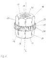
- figure 1 shows a first preferred embodiment of the threaded insert, while in figure 2 an axial sectional view of this thread insert is shown.
- This threaded insert comprises a cylindrical base body 10 which extends along its longitudinal axis L.
- This base body 10 has a first axial end 12 and a second axial end 14 .
- a central bore 40 is provided in the base body 10 .
- a thread is therefore arranged on a radial inner side 16 of the base body 10 .
- the connection insert can be equipped with a bayonet lock, a latching mechanism or a latching structure or with another connection construction.
- the base body instead of a bore with an internal thread, has an axial extension 50 which is arranged on the first 12 or second end 14 (see below). Since the extension 50 is provided with a connection contour 52, preferably a thread 52, a connection is made via the threaded bolt now present instead of via the internal thread.
- the preferred thread insert and its properties are exemplary for the structure, the function, the use and the production of connection inserts according to the invention.
- the cylindrical base body 10 is delimited in the axial direction by the first 12 and the second end 14 . It is preferably uniform in diameter, graduated or tapered or widened over its length. This applies both to a threaded insert with an internal thread 42 and to a connection insert with an axial extension 50.
- At least one radially circumferential collar 20 is arranged on a radial outer side 18 of the base body 10 . Compared to the rest of the base body 10, this collar 20 has the largest outside diameter. In addition, the collar 20 is not arranged on the first axial end 12 or on the second axial end 14 of the base body 10 . Rather, the collar 20 is in a central arrangement based on the length of the base body 10. According to a Figures 5 and 6 In the preferred embodiment of the present invention shown, collar 20 is positioned off-center with respect to the length of body 10 . At the same time, however, the collar 20 is at a distance from the first axial end 12 and from the second axial end 14 , so that the collar 20 does not form the axial termination of the base body 10 .
- a plurality of collars 20 are arranged on the radially outer side 18 of the base body 10 . While only one collar 20 preferably has an axial width of 10% to 60% of a total length of the base body 10, the same applies to the added axial widths of a plurality of collars arranged on the radial outside 18.
- the base body 10 comprises a radially projecting structure 30 on its radial outside 18.
- This structure 30 preferably runs in the axial direction of the base body 10.
- the structure 30 extends over the complete area between the collar 20 and the first axial end 12 and/or the second axial end 14 of the base body 10. It is also preferred that the structure 30 extends only in partial areas between the collar 20 and the first 12 and/or second axial end 14.
- the structure 30 is continuous in the areas described above, as shown in FIGS Figures 1 to 6 can be seen.
- the structure between the collar 20 and the first 12 and/or second axial end 14 is perforated. It follows that the preferred ridges 34 and indentations 36 running in the axial direction are continuous or interrupted or discontinuous between the collar 20 and the first 12 and/or the second axial end 14 .
- a circumferentially arranged knurling 32 is provided as the structure 30 .
- This knurling 32 consists of alternating ridges 34 and valleys 36, with the ridges 34 and valleys 36 preferably having an angular, rounded or curvilinear cross-sectional shape (not shown).
- the figures 1 and 2 show a preferred serrated knurling 32, while in figure 3 a torx-shaped knurling is provided as structure 30 .
- the collar 20 has an alternating arrangement of valleys 22 and elevations 24 in relation to their radial extension.
- the elevations 24 in particular form a pull-out safeguard in the axial direction of the base body 10. This pull-out safeguard acts in both axial directions, so that the threaded insert is secured against tensile and compressive loads in the axial direction.
- the collar 20 in general and the elevations 24 in particular thus form an axial undercut, the effect of which is further supported by the formation of the axial side surfaces 26 of the collar 20 .
- the side faces 26 preferably enclose an angle of at most 90° with the longitudinal axis L of the base body 10 . According to a further preferred embodiment, this angle is less than 90°.
- ⁇ 1 and ⁇ 2 designates the angle between the side surface 26, which faces the first axial end 12, and the longitudinal axis L of the base body.
- ⁇ 2 denotes the angle between the side surface 26, which faces the second axial end 14, and the longitudinal axis L of the base body 10.
- ⁇ 1 and ⁇ 2 can be the same size or different sizes. According to different preferred embodiments, the angles have a size of 90° ⁇ 1 , ⁇ 2 ⁇ 65°, more preferably 80° ⁇ 1 , ⁇ 2 ⁇ 70°. In the preferred embodiments of the figures 2 and 4 the angles ⁇ 1 and ⁇ 2 are of the same size and acute-angled.
- the peaks 24 and the valleys 22 are shaped differently. They are preferably sawtooth-like in accordance with figure 3 or flattened and concave according to figure 1 or generally angular, rounded or curvilinear in radial cross-section. While the shape of the collar 20 with the elevations 24 and the valleys 22 can vary, the functionality of the collar, which varies in diameter, must be ensured. This is because during embedding according to step S1 (see below), the elevations 24 cause plasticized plastic to accumulate on the collar 20 counter to the direction of embedding. This accumulation ensures that there is sufficient plasticized plastic that fills the structure 30 and the space between the side surface 26 and the radial outside 18 of the base body 10 in the angular range ⁇ 2 .
- the valleys 22 preferably allow the accumulated plastic to overflow sufficiently over the collar 20.
- This overflowing plastic is used to fill the structure 30 on the other side of the collar 20 and the angular area between the side surface 26 and the radial outside 18 of the base body 10 in the Angular range ⁇ 1 to be filled.
- the structure 30 preferably runs in the axial direction of the base body 10, this supports the flow of the plastic into the depressions 26.
- connection insert is in the Figures 7 and 8 shown.
- the connecting insert also includes the cylindrical base body 10 with the first 12 and second axial end 14.
- This base body 10 has the same features in its external design as those described above in general and/or with reference to the embodiments of FIG Figures 1 to 6 have been explained.
- connection insert in contrast to the thread insert, the connection insert according to Figures 7 and 8 a bolt-like axial extension 50 at its first axial end 12.
- the extension 50 preferably has a smaller diameter than the base body 10 and the collar 20. It is also preferred to provide the diameter of the extension 50 equal to or larger than the outside diameter of the base body 10 and/or the collar 20 .
- the base body 10 thus transitions into the extension 50 in a stepped manner at its axial end 12, with a continuous transition also being able to be implemented as an alternative.
- the extension 50 has a cylindrical, a conical, a stepped shape over its length or another shape (not shown).
- connection insert with extension 50 is integrally formed. It is also preferred that the connection insert is formed in two parts, in that the axial extension 50 is fixed in an inner opening of the connection insert, preferably screwed, glued, shrunk or otherwise fixed therein. According to a further preferred embodiment, the connection insert with extension 50 comprises an axial through-hole in order to realize a fluid connection on a component via the connection insert, for example.
- the extension 50 preferably has a thread 52 on its radial outside.
- other connection contours or constructions can also be realized at this point, such as preferably a latching contour, a plug-in connection contour or a wedging contour.
- the extension 50 is measured in terms of its axial length, beginning with the first axial End 12 of the body 10 is adaptable to specific connection requirements.
- the extension 50 therefore preferably has a length in the range from 40% to 200%, preferably 60% to 120%, of a length of the base body 10 .
- step S1 the material of a preformed plastic component is plasticized in a selected embedding area.
- the plasticizing takes place by supplying heat, inductively or with the help of ultrasound based on known methods.
- step S2 the threaded insert is pressed in the axial direction into the plasticized embedding area of the plastic component.
- the pressing-in preferably takes place with the second axial end 14 of the base body 10 in front.
- this bore is blocked, for example with a suitable mandrel or other suitably shaped construction. In this way, the plasticized plastic only flows around the structures on the radial outside 18 of the threaded insert.
- step S4 plasticized plastic is accumulated at the elevations 24 of the collar 20 (step S4). It follows that while the threaded insert is being pressed into the plastic component, the collar 20 pushes plasticized plastic in front of it in the area of the elevations 24 . In the area of the radial valleys 22, the accumulated plasticized plastic overflows in step S3. In this way, the valleys 22 as overflow areas ensure that sufficient plasticized plastic flows into the structure 30 between the collar 20 and the first axial end 12 of the base body. Furthermore, these overflow areas ensure that sufficient plasticized plastic wets the side surfaces 26 that face the first axial end 12 of the base body 10 .
- the plasticized plastic flows into the structure 30, which is arranged on one side or both sides of the collar 20 (step S5).
- This plasticized plastic fills the depressions 36 of the structure 30 almost completely or completely, so that the Plastic forms an anti-twist device for the threaded insert about its longitudinal axis L after it has hardened.
- the accumulation of the plasticized plastic on the collar 20 and the overflowing of the plasticized plastic that has accumulated on the collar 20 causes the lateral surfaces 26 to be preferably completely wetted on both sides with the plasticized plastic.
- the hardened plastic Due to the angular arrangement of the side faces 26 of the collar 20 compared to the radial outside 18 of the base body 10, the hardened plastic preferably forms acute-angled undercuts on these side faces 26. These acute-angled undercuts secure the position of the threaded insert in the axial direction. This means that the threaded insert is secured both against being pulled out and against further pressing into the plastic body.
- connection insert can also be fastened in a component made of plastic or metal with the aid of a molding method.
- Molding processes include what are known as primary molding processes, with which a component can be produced from a plasticized material, such as plastic or metal.
- These primary shaping processes preferably include injection molding of plastic and casting of metal. The molding process is explained using the injection molding process as an example.
- connection insert is positioned in an injection mold (not shown). Depending on the design of the connector insert, the interior of the connector insert is blocked by a pin or the like to prevent ingress of plastic or other material.
- plasticized plastic is injected into the injection mold and the connection insert is thereby encapsulated in step E2. In general, this is a plasticized, settable material, as mentioned above, so that the connection insert is molded into the component.
- the injection mold has been sufficiently filled with plastic, it hardens in step E7 the overmolded material.
- the component with the connection insert is removed from the injection mold (step E8).
- the method steps E3 to E6 therefore correspond to the method steps S3 to S6 of the embedding method described above, the description of which is hereby referred to.
- a cylindrical base body made of metal is provided.
- the cylindrical body consists of a piece of wire that has been cut or sheared off an endless wire in step SII.
- This cylindrical body has first and second ends (not shown).
- This base body is then positioned with the first axial end in a first die and with the second axial end in a second die (step S III).
- the first and second dies together define an internal cavity that defines in whole or in part the external shape of the threaded insert described above.
- the defined cavity has a cylindrical shape with a peripheral recess for forming the collar 20 described above.
- collar 20 is formed in a dedicated cavity at the interface between the first and second dies. This arrangement of the cavity allows sufficient demolding of the Insert even when the collar 20 has acutely oriented side surfaces 26 with respect to the longitudinal axis L of the Insert.
- step S III After the base body has been positioned in the first and second dies (step S III), this is preferably done by moving the first and second dies towards one another Die an upsetting and / or extrusion of the first (step S IV) and the second end (step SV) of the base body 10. Due to these processes, a circumferential collar 20 is formed, which compared to the rest of the base body 10 has the largest outer diameter. At the same time, the collar 20 is arranged at a distance from the first axial end 12 and the second axial end 14 of the base body 10 .
- the structure 30 is also formed on the radial outside 18 of the base body during upsetting and/or extrusion by the movement of the first and second dies.
- a rolling or extrusion of a radially protruding structure which is arranged on the radial outside 18 of the base body 10, takes place in step S VI.
- This molded structure 30 also extends parallel to the longitudinal axis L of the base body 10.
- the bolt-like axial extension 50 adjoining the first axial end 12 of the base body 10 is shaped in step SVII.
- One of the connection contours 52 mentioned above can then be provided on the extension 50 .
Landscapes
- Engineering & Computer Science (AREA)
- Mechanical Engineering (AREA)
- General Engineering & Computer Science (AREA)
- Manufacturing & Machinery (AREA)
- Injection Moulding Of Plastics Or The Like (AREA)
Description
- Die vorliegende Erfindung betrifft einen Verbindungseinsatz, insbesondere einen Gewindeeinsatz, der in ein Kunststoffbauteil einformbar oder einbettbar ist. Des Weiteren betrifft vorliegende Erfindung ein Einbettverfahren für diesen Verbindungseinsatz in das ausgeformte Kunststoffbauteil und ein Einformverfahren für diesen Verbindungseinsatz in ein auszuformendes Bauteil. Des Weiteren ist vorliegende Erfindung auf ein Herstellungsverfahren für diesen Verbindungseinsatz gerichtet und ein Bauteil mit Verbindungseinsatz gerichtet.
- Im Stand der Technik sind unterschiedliche Verbindungseinsätze, im Speziellen Gewindeeinsätze, bekannt. In Abhängigkeit davon, in welchem Bauteilmaterial ein derartiger Verbindungseinsatz befestigt werden soll, variiert die Gestaltung der Form eines derartigen Verbindungseinsatzes. So offenbart beispielsweise
US 6,676,352 B2 einen Gewindeeinsatz, der in eine vorgebohrte Öffnung eines Holzbauteils eingedreht oder eingeschlagen werden kann. Zu diesem Zweck weist dieser Verbindungseinsatz an seiner radialen Außenseite gewindeähnlich verlaufende Rippen auf, die sich in das Holz des Bauteils einschneiden. Dieser Verbindungseinsatz ist somit ähnlich einer Holzschraube aufgebaut und daher für Kunststoffbauteile nicht geeignet. - Es ist allgemein bekannt, Verbindungseinsätze in bereits ausgeformte Kunststoffbauteile einzubetten. Ein derartiges Einbetten erfolgt durch Zufuhr von Wärme zum Kunststoffbauteil, sodass lokal der Kunststoff plastifiziert wird. In diesen plastifizierten Kunststoff wird dann der Verbindungseinsatz eingepresst, sodass er nach Aushärten des Kunststoffs in dem Kunststoffbauteil befestigt ist. Für derartige einbettbare Verbindungseinsätze sind verschiedene Konstruktionen im Stand der Technik bekannt.
WO 2011/130070 A1 beschreibt beispielsweise einen einbettbaren Verbindungseinsatz, der einen zylindrischen Grundkörper mit einer radialen Außenseite aufweist. An dieser radialen Außenseite sind umlaufend wellenförmig verlaufende radial vorstehende Stege angeordnet. Während des Einbettens des Verbindungseinsatzes, das heißt während der Verbindungseinsatz in axialer Richtung in den plastifizierten Kunststoff gedrückt wird, schieben diese radial vorstehenden Stege plastifizierten Kunststoff vor sich her. Da der plastifizierte Kunststoff während des Einsetzens des Verbindungseinsatzes abkühlt und zudem ein schlechtes Fließverhalten aufweist, wird nur ein Teil der Zwischenräume zwischen den wellenförmig verlaufenden Stegen mit plastifiziertem Kunststoff ausgefüllt. Dies führt dazu, dass der Verbindungseinsatz nur eine geringe axiale Auszugsfestigkeit aufweist. - Ein weiterer Verbindungseinsatz ist in
WO 2011/109236 A1 beschrieben. Hier verlaufen die an der radialen Außenseite des zylindrischen Grundkörpers angeordneten radial vorstehenden Stege ebenfalls in Wellenform. Zudem sind diese Stege in axialer Richtung mit einer Neigung angeordnet. Daraus folgt, dass bezogen auf eine axiale Auszugsrichtung auch diese in annähernd axialer Richtung verlaufenden Stege nur eine begrenzte Auszugsfestigkeit bereitstellen können. -
WO 2011/130073 A1 beschreibt einen einbettbaren Verbindungseinsatz, der an seiner radialen Außenseite eine Mehrzahl von vorstehenden Verriegelungsnasen aufweist. Diese Verriegelungsnasen sind in axialer Einsetzrichtung des Verbindungseinsatzes spitz zulaufend ausgeformt, um das Einbetten zu erleichtern. Entgegen der Auszugsrichtung weisen diese Verriegelungsnasen Abstützflächen auf, die annähernd senkrecht zur Auszugsrichtung orientiert sind. Diese Abstützflächen sind jedoch verglichen zur verbleibenden Fläche der radialen Außenseite klein ausgebildet, sodass bereits kein vollständiges Hinterfließen durch den plastifizierten Kunststoff aufgrund dessen hoher Oberflächenspannung stattfinden kann. Damit ist gleichzeitig verbunden, dass der aushärtende Kunststoff den Verbindungseinsatz nicht ausreichend im Kunststoffbauteil verriegelt. - Ein weiterer Verbindungseinsatz, im Speziellen ein Gewindeeinsatz, ist in
DE 100 13 091 A1 beschrieben. Während an einem Ende ein radial umlaufender Kragen angeordnet ist, befinden sich an der radialen Außenseite des zylindrischen Grundkörpers mehrere aufeinander folgende konische Abschnitte. Diese konischen Abschnitte verjüngen sich in axialer Einsetzrichtung des Gewindeeinsatzes. Auf diese Weise entsteht eine Mehrzahl von radial umlaufenden Flächen, die einen Hinterschnitt und somit eine Auszugssicherung des Gewindeeinsatzes bilden könnten. Da jedoch auch hier während des Einbettens nur ein träges Fließen des plastifizierten Kunststoffs stattfindet, hinterfließt der plastifizierte Kunststoff die hier ausgebildeten radial umlaufenden Kanten nur unvollständig. Dies liegt unter anderem daran, dass die in axialer Richtung verlaufenden Fließkanäle für den plastifizierten Kunststoff nur geringe Bereiche der radialen Außenseite des Grundkörpers abdecken. Ein weiterer Nachteil besteht darin, dass zwar eine axiale Auszugssicherung bereitgestellt wird, die axiale Festigkeit in Einsetzrichtung jedoch nur begrenzt gegeben ist. Dies liegt unter anderem daran, dass die konisch geformte radiale Außenseite des Grundkörpers ein axiales Eindringen des Gewindeeinsatzes in das Kunststoffbauteil unterstützt. - Ein metallischer Gewindeeinsatz zum Einbau in Werkstücke aus thermoplastischem Kunststoff unter thermischer Erweichung des Kunststoffmaterials ist in
DE 30 16 590 A1 beschrieben. Der Gewindeeinsatz umfasst mindestens einen Erhebungen und Vertiefungen aufweisenden Verankerungsabschnitt. Oberhalb des Verankerungsabschnittes ist ein zylindrischer Dichtungsabschnitt mit einer außenliegenden Ringnut vorgesehen, in die ein aus einem gegenüber der beim Einbau entwickelten Wärme relativ geringen Wärmeleitwerts - beständigen Material gefertigter Dichtungsring eingebracht ist.
- Die
US 3,125,146 A zeigt einen Gewindeeinsatz mit einem Erhebungen und Vertiefungen aufweisenden Bund. - Die vorliegende Erfindung stellt sich daher die Aufgabe, einen einbettbaren Verbindungseinsatz bereitzustellen, der im Vergleich zum Stand der Technik mit einer verlässlicheren Auszugssicherheit installierbar und insbesondere gegen Verdrehen gesichert ist.
- Die oben genannte Aufgabe wird durch einen Verbindungseinsatz, insbesondere einen Gewindeeinsatz, gemäß dem unabhängigen Patentanspruch 1 gelöst. Des Weiteren definiert der unabhängige Patentanspruch 9 ein Einbettverfahren für diesen Verbindungseinsatz in einem ausgeformten Kunststoffbauteil. Zudem ist im unabhängigen Patentanspruch 13 ein Einformverfahren zum Einformen des Verbindungseinsatzes in ein herzustellendes Bauteil während eines Urformverfahrens definiert. Darüber hinaus offenbart vorliegende Erfindung ein Herstellungsverfahren für einen derartigen Verbindungseinsatz gemäß dem unabhängigen Patentanspruch 17.
- Außerdem offenbart vorliegende Erfindung ein Bauteil mit dem oben genannten Verbindungseinsatz gemäß Anspruch 20.
- Vorteilhafte Ausgestaltungen und Weiterentwicklungen vorliegender Erfindung gehen aus der folgenden Beschreibung, den begleitenden Zeichnungen sowie den anhängenden Patentansprüchen hervor.
- Der erfindungsgemäße Verbindungseinsatz, insbesondere ein Gewindeeinsatz oder ein Verbindungseinsatz mit Gewindebolzen, der in ein Kunststoffbauteil einformbar ist, weist die folgenden Merkmale auf: einen zylindrischen Grundkörper mit einer radialen Außenseite sowie einem ersten und einem zweiten axialen Ende, mindestens einen an der radialen Außenseite des Grundkörpers angeordneten umlaufenden Bund, der im Vergleich zum übrigen Grundkörper zumindest abschnittsweise den größten Außendurchmesser aufweist und der beabstandet zum ersten und zweiten axialen Ende des Grundkörpers angeordnet ist, und eine an der radialen Außenseite des Grundkörpers angeordnete radial vorstehende Struktur.
- Der erfindungsgemäße Verbindungseinsatz ist in ein auszuformendes oder ein ausgeformtes Kunststoffbauteil einformbar, sodass ein beliebiges Verbindungselement oder ein anderes Bauteil in oder an diesem Verbindungseinsatz befestigt werden kann. Gemäß einer bevorzugten Ausgestaltung vorliegender Erfindung wird unter Einformen ein Einbetten in ein bereits ausgeformtes Kunststoffbauteil verstanden. Dazu wird zunächst das Bauteilmaterial in einem ausgewählten Bereich plastifiziert, um dort den Verbindungseinsatz einzubetten bzw. einzupressen. Dies ist unten näher erläutert. Gemäß einer weiteren bevorzugten Ausführungsform umfasst Einformen das Anordnen und Befestigen des Verbindungseinsatzes in einem Bauteil während eines Urformprozesses zur Herstellung des Bauteils. Zu derartigen Urformverfahren zählen beispielsweise Gießen, Druckgießen, Sprühkompaktieren, Spritzgießen, Extrusionsblasen, Extrusion, Sintern, Galvanoformen und Rapid Prototyping. Daher umfasst der Verbindungseinsatz vorzugsweise Gewindeeinsätze, Einsätze zum Bereitstellen eines Bayonettverschlusses, Einsätze, die eine Schnappverbindung realisieren, Einsätze mit einem bolzenartigen axialen Fortsatz, beispielsweise mit Gewinde, sowie alle anderen Verbindungssysteme, mit denen zwei Bauteile aneinander gekoppelt werden können. Im Weiteren wird der erfindungsgemäße Aufbau, das Herstellungsverfahren sowie das Verfahren zum Einbetten und das Verfahren zum Einformen des Verbindungseinsatzes in einem Bauteil anhand eines Gewindeeinsatzes erläutert. Daher gelten alle konstruktiven und funktionellen Eigenschaften des im Folgenden beschriebenen Gewindeeinsatzes allgemein für die unterschiedlichen Verbindungseinsätze.
- Der erfindungsgemäße Gewindeeinsatz erzielt aufgrund der speziellen Gestaltung seiner radialen Außenseite verlässliche axiale Auszugsfestigkeiten, während gleichzeitig das Einbetten in einem ausgeformten Kunststoffbauteil sowie das Einformen in einem auszuformenden Kunststoff- oder Metallbauteil und damit das Verankern des Gewindeeinsatzes in diesem Bauteil im Vergleich zum Stand der Technik verbessert sind. Der erfindungsgemäße Gewindeeinsatz weist an seiner radialen Außenseite einen umlaufenden Bund auf, der gerade nicht an den beiden Enden des Grundkörpers angeordnet ist. Auf diese Weise erzeugt dieser mindestens eine radial vorstehende Bund, der zudem auch den größten Außendurchmesser des gesamten Gewindeeinsatzes aufweist, eine hohe axiale Festigkeit in beide axiale Belastungsrichtungen des Gewindeeinsatzes auf. Dies wird vorzugsweise nur dadurch realisiert, dass der radial umlaufende Bund einen verriegelnden Hinterschnitt sowohl in die axiale Auszugsrichtung des Gewindeeinsatzes wie auch in seine Einbettrichtung bildet. In Kombination mit dieser axialen Stabilität des Gewindeeinsatzes wird durch die an der radialen Außenseite zusätzlich angeordnete radial vorstehende Struktur eine Verdrehsicherung des Gewindeeinsatzes um seine Längsachse realisiert. Zusammenfassend ist hervorzuheben, dass der befestigende Formschluss zwischen dem Verbindungseinsatz und dem Bauteil bzw. dem Bauteilmaterialgerade durch die erhabenen Hinterschnitte der äußeren Gestaltung des Verbindungseinsatzes, im Speziellen des zylindrischen Grundkörpers, erzeugt wird. Diese erhabenen Hinterschnitte sind wirksamer als die aus dem Stand der Technik bekannten Einstiche und Vertiefungen an der radialen Außenseite von Verbindungseinsätzen.
- Um diese Verdrehsicherung zu garantieren, ist die erfindungsgemäße Gestaltung derart, dass die radial vorstehende Struktur kontinuierlich und/oder diskontinuierlich in Längsrichtung des Grundkörpers, vorzugsweise parallel zur Längsachse des Grundkörpers, verläuft. Basierend auf dieser Ausrichtung bzw. dieses Verlaufs der vorstehenden Struktur bilden sich radiale Hinterschnitte aus, die einer Drehung des Gewindeeinsatzes blockierend entgegenwirken.
- Bevorzugt ist der mindestens eine umlaufende Bund in axialer Richtung des Grundkörpers durch zwei Seitenflächen begrenzt, die zumindest abschnittsweise jeweils einen Winkel von maximal 90° mit der Längsachse des Grundkörpers, insbesondere einen Winkel kleiner 90°, einschließen. Untersuchungen haben gezeigt, dass gerade ein umlaufender Bund mit zwei gegenüberliegend angeordneten und somit in beide Richtungen als Hinterschnitt wirkenden Seitenflächen die axiale Festigkeit des Gewindeeinsatzes vorteilhaft unterstützt. Dabei ist ein weiteres Kriterium, in welchem Winkel die Seitenflächen zur Längsachse des Gewindeeinsatzes angeordnet sind. Erstaunlicherweise erzeugt gerade ein Winkel von 90° und kleiner zwischen der Seitenfläche und der Längsachse des Grundkörpers eine weitere Steigerung der axialen Festigkeit des Gewindeeinsatzes innerhalb des Kunststoffbauteils. Daher werden gemäß unterschiedlicher bevorzugter Ausführungsformen unterschiedliche spitze Winkel zwischen den Seitenflächen des Bundes und der Längsachse des Grundkörpers genutzt, die je nach Belastung des Gewindeeinsatzes im Kunststoffbauteil konfiguriert sind. Besonders bevorzugte Winkel liegen beispielsweise im Bereich zwischen 85° und 70°.
- Um das unten beschriebene Einbettverfahren des Gewindeeinsatzes zu unterstützen, weist der Bund des Gewindeeinsatzes vorzugsweise in einer umfänglichen Verlaufsrichtung einen abschnittsweise sich ändernden Durchmesser auf, sodass eine Mehrzahl von radialen Tälern und Erhebungen im Bund angeordnet sind. Erstaunlicherweise behindert der umlaufende Bund trotz seiner Dimensionierung nicht das Einbetten des Gewindeeinsatzes im Kunststoffbauteil, denn gerade die radialen Täler sorgen dafür, dass ausreichend plastifizierter Kunststoff über den Bund überströmen und somit sich in der Struktur an der radialen Außenseite des Grundkörpers verteilen kann. Dieses Überströmen in den radialen Tälern bewirkt ebenfalls, dass die spitzen Winkel zwischen den Seitenflächen des Bundes und der radialen Außenseite des Gewindeeinsatzes vollständig oder nahezu vollständig mit Kunststoff ausgefüllt werden. Nach dem Erstarren des zuvor plastifizierten Kunststoffs bewirken gerade die Erhebungen im umlaufenden Bund, die bereits oben beschriebene axiale Festigkeit des Gewindeeinsatzes.
- Gemäß einer weiteren bevorzugten Ausführungsform vorliegender Erfindung besteht die radial vorstehende Struktur benachbart zum umlaufenden Bund aus einer vorzugsweise bereichsweise parallel und/oder schräg zur Längsachse des Grundkörpers verlaufenden Rändelung, die einseitig oder beidseitig vom Bund angeordnet ist. Es ist in diesem Zusammenhang bevorzugt, dass sich diese Struktur über den gesamten Bereich zwischen den axialen Enden des Grundkörpers und dem umlaufenden Bund erstreckt. Gleicherweise ist es bevorzugt, dass diese Struktur nur Teilbereiche zwischen den axialen Enden des Grundkörpers und dem Bund ausfüllt. Gemäß einer weiteren bevorzugten Ausführungsform vorliegender Erfindung besteht diese Rändelung aus gleichmäßig zueinander beabstandeten radial vorstehenden Stegen, die eine eckige, abgerundete oder krummlinige Querschnittsform aufweisen. Die bisher oben beschriebene Struktur des Verbindungseinsatzes ist für unterschiedliche
- Verbindungseinsätze anwendbar. Daher ist eine erfindungsgemäße Gestaltung derart, dass der Verbindungseinsatz eine zentrale Bohrung mit der radialen Innenseite aufweist, an der eine Verbindungsstruktur vorgesehen ist. Diese Verbindungsstruktur bildet ein Gewinde, einen Bajonettverschluss, eine radiale Rändelung oder eine andere Verbindungskonstruktion, die mit einem einsetzbaren Verbindungselement zusammenwirkt.
- Gemäß einer weiteren bevorzugten Ausführungsform vorliegender Erfindung ist der mindestens eine umlaufende Bund axial mittig und/oder benachbart zu den axialen Enden des zylindrischen Grundkörpers angeordnet. Dabei ist der Bund aber nicht angrenzend an die axialen Enden angeordnet. Gemäß einer anderen bevorzugten Ausführungsform vorliegender Erfindung weist der mindestens eine Bund oder eine Mehrzahl von umlaufenden Bünden einzeln oder gemeinsam eine axiale Breite von 10 % bis 60 % einer Gesamtlänge des Grundkörpers auf. Gemäß einer weiteren bevorzugten Ausführungsform umfasst diese axiale Breite 20 % bis 40 % der Gesamtlänge des Grundkörpers. Mit Hilfe einer Mehrzahl von umlaufenden Bünden wird die axiale Festigkeit des Gewindeeinsatzes weiter gesteigert.
- Gemäß einer weiteren erfindungsgemäßen Gestaltung des Verbindungseinsatzes umfasst der zylindrische Grundkörper an seinem ersten axialen Ende einen bolzenartigen axialen Fortsatz. Vorzugsweise ist dieser Fortsatz stufenförmig vom Grundkörper abgesetzt und/oder besitzt vorzugsweise eine Länge im Bereich von 40 % bis 200 % einer Länge des Grundkörpers. Des Weiteren ist es bevorzugt, den Fortsatz als einen Verbindungsbolzen mit einem Außengewinde oder einer Verrastungskontur oder einer Steckverbindungskontur auszubilden.
- Der erfindungsgemäß bevorzugte Verbindungseinsatz mit axialem Fortsatz stellt eine konstruktive Alternative zum Gewindeeinsatz mit Innengewinde dar. Während die erforderlichen Schritte zum Einformen die gleichen sind wie beim Gewindeeinsatz mit Innengewinde, werden weitere Verbindungsmöglichkeiten bereitgestellt. Denn bereits ein Aufstecken eines Verbindungselements auf den Fortsatz oder ein Verrasten an dem Fortsatz stellt eine verlässliche Verbindung her. Zudem ist der Verbindungseinsatz mit axialem Fortsatz günstig mittels Kaltschlagen und vorzugsweise Rollen des Gewindes auf dem Fortsatz herstellbar. Als Ergebnis liegt ein hochfester Verbindungseinsatz mit Gewindebolzen vor, der kostengünstig im Vergleich zu Zerspanungsverfahren herstellbar ist.
- Des Weiteren umfasst vorliegende Erfindung ein Bauteil mit einem eingebetteten oder eingeformten Verbindungseinsatz gemäß der obigen Beschreibung. Dieses Bauteil besteht vorzugsweise aus Kunststoff, der mit Hilfe der Zufuhr von Wärme plastifizierbar ist, sodass der Verbindungseinsatz in das bereits ausgeformte Bauteil einbettbar ist. Es ist zudem bevorzugt, das Bauteil aus Metall bereitzustellen, in welches ebenfalls der Verbindungseinsatz eingeformt werden kann. Gemäß einer weiteren Ausführungsform vorliegender Erfindung ist der Verbindungseinsatz auch mit Hilfe anderer Verfahren in ein Kunststoffbauteil einformbar. Zu diesem Zweck wird der Verbindungseinsatz beispielsweise noch vor dem Ausformen des Kunststoff- oder Metallbauteils in einer dafür vorgesehenen Form positioniert und nachfolgend durch den Kunststoff oder das Metall des Bauteils eingeformt.
- Vorliegende Erfindung umfasst des Weiteren ein Einbettverfahren für den oben beschriebenen Verbindungseinsatz, das die folgenden Schritte aufweist: Plastifizieren von Material in einem Einbettbereich eines ausgeformten Kunststoffbauteils, Einpressen des Verbindungseinsatzes in axialer Richtung in den Einbettbereich derart, dass Material des Kunststoffbauteils an dem Bund aufgestaut wird und zumindest teilweise den Bund überströmt, sodass der Bund nach Materialaushärtung eine axiale Auszugssicherung bildet. Wie bereits oben erläutert worden ist, führen gerade die am Bund des Verbindungselements vorgesehenen radialen Täler und Erhebungen dazu, dass während des Einpressens das plastifizierte Material in den radialen Tälern den Bund überströmt und an den Erhebungen aufgestaut wird. Diese Strömungsverhältnisse des plastifizierten Kunststoffs am erfindungsgemäß bevorzugt geformten Bund sorgen für ein Ausfüllen nahezu aller oder jeglicher Freiräume an der radialen Außenseite des Grundkörpers durch plastifizierten Kunststoff, sodass der Verbindungseinsatz nach Aushärten des Kunststoffs optimal im Kunststoffbauteil befestigt ist.
- Während des Einbettverfahrens ist es zudem bevorzugt, dass das plastifizierte Material in die axiale Rändelung benachbart zum Bund fließt, sodass dadurch nach Aushärtung des Kunststoffs eine Verdrehsicherung des Verbindungseinsatzes realisiert wird. Weiterhin erfindungsgemäß bevorzugt überströmt das plastifizierte Material des Kunststoffbauteils an dem Bund beidseitig jeweils eine axiale Seitenfläche, sodass das plastifizierte Material nach einem Aushärten einen spitzwinkligen Hinterschnitt als beidseitige axiale Auszugssicherung bildet.
- Vorliegende Erfindung offenbart zudem ein Einformverfahren für den Verbindungseinsatz, der oben beschrieben worden ist. Das Einformverfahren realisiert das Befestigen des Verbindungseinsatzes in einem Bauteil, während das Bauteil mit Hilfe eines Urformverfahrens, wie bspw. Gießen oder Spritzgießen, aus Metall oder Kunststoff hergestellt wird. Das Einformverfahren umfasst die folgenden Schritte: Positionieren des Verbindungseinsatzes in einer Form, vorzugsweise Spritzform, Umgeben, vorzugsweise Umspritzen, des Verbindungseinsatzes mit einem plastifizierten aushärtbaren Material, wobei der Verbindungseinsatz in ein Bauteil eingeformt wird, und Aushärten des umgebenden, vorzugsweise umspritzten, Materials und Entformen des Bauteils mit Verbindungseinsatz aus der Form. In diesem Zusammenhang ist es ebenfalls bevorzugt, dass der Bund des Verbindungselements radiale Täler und Erhebungen aufweist, sodass während des Umspritzens oder Umgießens das plastifizierte Material in den radialen Tälern den Bund überströmt und an den Erhebungen aufgestaut wird. Weiterhin bevorzugt fließt das plastifizierte Material während des Einformverfahrens in eine axiale Rändelung benachbart zum Bund, sodass dadurch nach Aushärtung eine Verdrehsicherung entsteht. Gemäß einer weiteren bevorzugten Ausführungsform überströmt das plastifizierte Material an dem Bund beidseitig jeweils eine axiale Seitenfläche, sodass das plastifizierte Material nach einem Aushärten einen spitzwinkligen Hinterschnitt als beidseitige axiale Auszugssicherung bildet. Aus obiger Beschreibung folgt, dass das Einformverfahren ähnliche Merkmale und Vorteile wie das Einbettverfahren aufweist, so dass zur Erläuterung des Einformverfahrens ebenfalls die Beschreibung des Einbettverfahrens herangezogen wird. Lediglich der Ausgangspunkt des jeweiligen Befestigungsverfahrens ist unterschiedlich.
- Vorliegende Erfindung umfasst des Weiteren ein Herstellungsverfahren des oben beschriebenen Verbindungseinsatzes. Dieses Herstellungsverfahren weist die folgenden Schritte auf: Bereitstellen eines zylindrischen Grundkörpers aus Metall, der ein erstes und ein zweites Ende umfasst, Positionieren des Grundkörpers mit dem ersten Ende in oder zu einer ersten Matrize und mit dem zweiten Ende in oder zu einer zweiten Matrize, Aufstauchen und/oder Fließpressen des ersten und zweiten Endes des Grundkörpers, sodass ein zumindest abschnittsweise umlaufender Bund ausgeformt wird, der im Vergleich zum übrigen Grundkörper den größten Außendurchmesser aufweist und beabstandet zum ersten und zweiten Ende des Grundkörpers angeordnet ist. Es versteht sich, dass das Herstellungsverfahren durch weitere Formgebungsschritte ergänzt werden kann, um hier den erfindungsgemäß bevorzugten Verbindungseinsatz zu erzielen.
- Das erfindungsgemäß bevorzugte Herstellungsverfahren nutzt ein kostengünstiges Kaltfließpressen oder Kaltschlagen, wie oben bereits angedeutet worden ist, um die oben beschriebenen erfindungsgemäß bevorzugten konstruktiven Merkmale des Verbindungseinsatzes zu erzeugen. Dadurch sind höherfeste Stähle mit Festigkeiten im Bereich von 8.8 bis 10.9 gemäß DIN EN ISO 898-1 einsetzbar, die gerade bei einem Innengewinde oder einem Gewindebolzen bzw. -fortsatz des Verbindungseinsatzes verlässliche Verbindungseigenschaften erzielen. Beim Einsatz von Aluminium als Material des Verbindungseinsatzes stellt das Verfahren der Kaltverfestigung belastbarere Gewinde im Vergleich zu Gewinden aus spanender Herstellung bereit. In gleicher Weise ist es ebenfalls möglich, das Warmpressen anzuwenden oder den Verbindungseinsatz mittels Gießen herzustellen. Aus wirtschaftlichen Gründen wird aber das Kaltfließpressen favorisiert, da sich auf diese Weise gerade der speziell geformte umlaufende Bund des Verbindungseinsatzes ausformen lässt. Zu diesem Zweck wird bevorzugt ein Drahtstück von einem Endlosdraht abgeschert und als Grundkörper in der ersten und zweiten Matrize positioniert. Die erste und zweite Matrize geben in komplementärer Ausgestaltung die spätere Form des Verbindungseinsatzes vor. So ist es gemäß einer bevorzugten Ausführungsform des Herstellungsverfahrens vorgesehen, dass nach dem Aufstauchen und/oder Fließpressen des Drahtstücks in der ersten und der zweiten Matrize ein zylindrischer Grundkörper mit einem umlaufenden Bund vorliegt. Es ist ebenfalls bevorzugt, dass bereits während des Aufstauchens und/oder Fließpressens der Bund mit den oben beschriebenen radialen Tälern und Erhebungen ausgeformt wird. Gemäß einer weiteren bevorzugten Ausführungsform wird neben der gerade beschriebenen Formgestaltung des Bundes auch die radiale Außenseite zwischen Bund und den Enden des Grundkörpers mit der oben beschriebenen Struktur versehen. Gemäß einer anderen bevorzugten Herstellungsroute ist es ebenfalls bevorzugt, die radiale Struktur sowie die Formgestaltung des Bundes durch Rollen herzustellen.
- Zur Herstellung eines Verbindungseinsatzes mit axialem Fortsatz, wie er oben beschrieben worden ist, erfolgt ein Ausformen eines sich an das erste axiale Ende des Grundkörpers anschließenden bolzenartigen axialen Fortsatzes. Entsprechend der angestrebten Verbindungskonstruktion umfasst der Fortsatz ein Gewinde, eine Verrastungskontur oder eine Kontur zur Herstellung einer Steckverbindung.
- Die bevorzugten Ausführungsformen vorliegender Erfindung werden unter Bezugnahme auf die begleitende Zeichnung näher erläutert. Es zeigen:
- Figur 1
- eine erste bevorzugte Ausführungsform des Verbindungseinsatzes vorliegender Erfindung,
- Figur 2
- eine axiale Schnittdarstellung des Verbindungseinsatzes gemäß
Figur 1 , - Figur 3
- eine zweite bevorzugte Ausführungsform des erfindungsgemäßen Verbindungseinsatzes,
- Figur 4
- einen axialen Schnitt durch die Ausführungsform gemäß
Figur 3 , - Figur 5
- eine dritte bevorzugte Ausführungsform des erfindungsgemäßen Verbindungseinsatzes,
- Figur 6
- eine axiale Schnittdarstellung der Ausführungsform gemäß
Figur 5 , - Figur 7
- eine dritte bevorzugte Ausführungsform des erfindungsgemäßen Verbindungseinsatzes mit einem axialen Fortsatz,
- Figur 8
- einen axialen Schnitt durch die Ausführungsform gemäß
Figur 7 , - Figur 9
- ein Flussdiagramm einer bevorzugten Ausführungsform des Einbettverfahrens für den erfindungsgemäß bevorzugten Verbindungseinsatz,
- Figur 10
- ein Flussdiagramm einer bevorzugten Ausführungsform des Einformverfahrens für den erfindungsgemäß bevorzugten Verbindungseinsatz und
- Figur 11
- ein Flussdiagramm einer bevorzugten Ausführungsform eines Herstellungsverfahrens einer bevorzugten Ausführungsform des Verbindungseinsatzes.
- Im Folgenden wird der erfindungsgemäße Verbindungseinsatz anhand der bevorzugten Ausführungsform eines Gewindeeinsatzes erläutert.
Figur 1 zeigt eine erste bevorzugte Ausführungsform des Gewindeeinsatzes, während inFigur 2 eine axiale Schnittdarstellung dieses Gewindeeinsatzes dargestellt ist. Dieser Gewindeeinsatz umfasst einen zylindrischen Grundkörper 10, der sich entlang seiner Längsachse L erstreckt. Dieser Grundkörper 10 weist ein erstes axiales Ende 12 und ein zweites axiales Ende 14 auf. Da es sich in der bevorzugten Ausführungsform der vorliegenden Erfindung um einen Gewindeeinsatz handelt, ist eine zentrale Bohrung 40 im Grundkörper 10 vorgesehen. An einer radialen Innenseite 16 des Grundkörpers 10 ist daher ein Gewinde angeordnet. Ebenfalls bevorzugt kann man den Verbindungseinsatz mit einem Bayonettverschluss, einem Verrastungsmechanismus bzw. einer Verrastungsstruktur oder mit einer anderen Verbindungskonstruktion ausstatten. Gemäß einer weiteren bevorzugten Ausführungsform weist der Grundkörper anstelle einer Bohrung mit Innengewinde einen axialen Fortsatz 50 auf, der am ersten 12 oder zweiten Ende 14 angeordnet ist (siehe unten). Da der Fortsatz 50 mit einer Verbindungskontur 52, vorzugsweise ein Gewinde 52, versehen ist, wird eine Verbindung anstelle über das Innengewinde über den nun vorliegenden Gewindebolzen hergestellt. Der bevorzugte Gewindeeinsatz und seine Eigenschaften stehen exemplarisch für den Aufbau, die Funktion, die Verwendung sowie die Herstellung von erfindungsgemäßen Verbindungseinsätzen. - Der zylindrische Grundkörper 10 wird in axialer Richtung durch das erste 12 und das zweite Ende 14 begrenzt. Über seine Länge ist er vorzugsweise im Durchmesser gleichmäßig, abgestuft oder sich verjüngend oder verbreiternd ausgeformt. Dies gilt sowohl für einen Gewindeeinsatz mit Innengewinde 42 wie auch für einen Verbindungseinsatz mit axialem Fortsatz 50.
- An einer radialen Außenseite 18 des Grundkörpers 10 ist mindestens ein radial umlaufender Bund 20 angeordnet. Dieser Bund 20 weist im Vergleich zum übrigen Grundkörper 10 den größten Außendurchmesser auf. Zudem ist der Bund 20 nicht am ersten axialen Ende 12 oder am zweiten axialen Ende 14 des Grundkörpers 10 angeordnet. Vielmehr befindet sich der Bund 20 in einer mittigen Anordnung bezogen auf die Länge des Grundkörpers 10. Gemäß einer in den
Figuren 5 und 6 gezeigten bevorzugten Ausführungsform vorliegender Erfindung ist der Bund 20 außermittig im Hinblick auf die Länge des Grundkörpers 10 angeordnet. Gleichzeitig ist der Bund 20 aber beabstandet vom ersten axialen Ende 12 und vom zweiten axialen Ende 14, sodass der Bund 20 nicht den axialen Abschluss des Grundkörpers 10 bildet. - Gemäß einer weiteren bevorzugten Ausführungsform vorliegender Erfindung (nicht gezeigt) ist eine Mehrzahl von Bünden 20 an der radialen Außenseite 18 des Grundkörpers 10 angeordnet. Während nur ein Bund 20 vorzugsweise eine axiale Breite von 10 % bis 60 % einer Gesamtlänge des Grundkörpers 10 aufweist, gilt das Gleiche für die addierten axialen Breiten mehrerer an der radialen Außenseite 18 angeordneter Bünde. Vorzugsweise erstreckt sich die Breite eines Bundes 20 oder mehrerer gedacht aneinander gereihter Bünde über 20 % bis 40 % der Gesamtlänge des Grundkörpers 10.
- Des Weiteren umfasst der Grundkörper 10 an seiner radialen Außenseite 18 eine radial vorstehende Struktur 30. Diese Struktur 30 verläuft vorzugsweise in axialer Richtung des Grundkörpers 10. Gemäß einer bevorzugten Ausführungsform der
Figuren 1 bis 6 erstreckt sich die Struktur 30 über den vollständigen Bereich zwischen dem Bund 20 und dem ersten axialen Ende 12 und/oder dem zweiten axialen Ende 14 des Grundkörpers 10. Es ist ebenfalls bevorzugt, dass sich die Struktur 30 nur in Teilbereichen zwischen dem Bund 20 und dem ersten 12 und/oder zweiten axialen Ende 14 erstreckt. Gemäß einer weiteren bevorzugten Ausführungsform vorliegender Erfindung verläuft die Struktur 30 kontinuierlich in den oben beschriebenen Bereichen, wie es in denFiguren 1 bis 6 zu erkennen ist. Des Weiteren ist es bevorzugt, dass die Struktur zwischen dem Bund 20 und dem ersten 12 und/oder zweiten axialen Ende 14 durchbrochen ist. Daraus folgt, dass die bevorzugten in axialer Richtung verlaufenden Stege 34 und Vertiefungen 36 kontinuierlich oder unterbrochen bzw. diskontinuierlich zwischen dem Bund 20 und dem ersten 12 und/oder dem zweiten axialen Ende 14 verlaufen. - Gemäß den in den
Figuren 1 bis 6 gezeigten Ausführungsformen vorliegender Erfindung ist als Struktur 30 eine umfänglich angeordnete Rändelung 32 vorgesehen. Diese Rändelung 32 besteht aus sich abwechselnden Stegen 34 und Vertiefungen 36, wobei die Stege 34 und die Vertiefungen 36 vorzugsweise eine eckige, abgerundete oder krummlinige Querschnittsform (nicht gezeigt) aufweisen. DieFiguren 1 und2 zeigen eine bevorzugte gezackte Rändelung 32, während inFigur 3 eine torxförmige Rändelung als Struktur 30 vorgesehen ist. - Sobald der Gewindeeinsatz in ein Kunststoffbauteil eingebettet wird, strömt Kunststoff in die Vertiefungen 36 und härtet dort aus. Auf diese Weise bildet der ausgehärtete Kunststoff in den Vertiefungen 36 einen axialen Hinterschnitt, der ein Drehen des Gewindeeinsatzes um seine Längsachse L blockiert. In gleicher Weise wirkt auch der Aufbau des Bundes 20 aus Tälern 22 und Erhebungen 24, der unten näher erläutert ist.
- Gemäß den
Figuren 1 und2 weist der Bund 20 eine abwechselnde Anordnung von Tälern 22 und Erhebungen 24 bezogen auf ihre radiale Erstreckung auf. Gerade die Erhebungen 24 bilden nach dem Einformen bzw. Einpressen des Gewindeeinsatzes in ein Kunststoffbauteil eine Auszugssicherung in axialer Richtung des Grundkörpers 10. Diese Auszugssicherung wirkt in beide axiale Richtungen, sodass der Gewindeeinsatz gegen Zug- und Druckbelastung in axialer Richtung gesichert ist. Der Bund 20 allgemein und gerade die Erhebungen 24 bilden somit einen axialen Hinterschnitt, dessen Wirkung durch die Ausbildung der axialen Seitenflächen 26 des Bundes 20 noch unterstützt wird. - Vorzugsweise schließen die Seitenflächen 26 mit der Längsachse L des Grundkörpers 10 einen Winkel von maximal 90° ein. Gemäß einer weiter bevorzugten Ausführungsform ist dieser Winkel kleiner als 90°. Zur Erläuterung ist dieser Winkel als γ1 und γ2 in den
Figuren 2 und4 dargestellt. γ1 bezeichnet den Winkel zwischen der Seitenfläche 26, die dem ersten axialen Ende 12 zugewandt ist, und der Längsachse L des Grundkörpers. γ2 bezeichnet den Winkel zwischen der Seitenfläche 26, die dem zweiten axialen Ende 14 zugewandt ist, und der Längsachse L des Grundkörpers 10. γ1 und γ2 können gleich groß oder unterschiedlich groß sein. Gemäß unterschiedlicher bevorzugter Ausführungsformen haben die Winkel eine Größe von 90° < γ1, γ2 < 65°, weiter bevorzugt 80°≤ γ1, γ2 ≤ 70°. In den bevorzugten Ausführungsformen derFiguren 2 und4 sind die Winkel γ1 und γ2 gleich groß und spitzwinklig ausgebildet. - Wie man anhand der unterschiedlichen Ausgestaltungen des Bundes 20 in den
Figuren 1 bis 6 erkennen kann, sind die Erhebungen 24 und die Täler 22 unterschiedlich geformt. Vorzugsweise sind sie sägezahnähnlich gemäßFigur 3 oder abgeflacht und konkav gemäßFigur 1 oder allgemein im radialen Querschnitt eckig, abgerundet oder krummlinig ausgebildet. Während die Formgebung des Bundes 20 mit den Erhebungen 24 und den Tälern 22 unterschiedlich ausfallen kann, muss die Funktionalität des im Durchmesser variierend geformten Bundes gewährleistet sein. Denn beim Einbetten gemäß Schritt S1 (siehe unten) bewirken die Erhebungen 24 ein Aufstauen von plastifiziertem Kunststoff am Bund 20 entgegen der Einbettrichtung. Dieses Aufstauen sorgt für ausreichenden plastifizierten Kunststoff, der die Struktur 30 sowie den Raum zwischen der Seitenfläche 26 und der radialen Außenseite 18 des Grundkörpers 10 im Winkelbereich γ2 ausfüllt. - Gleichzeitig gestatten bevorzugt die Täler 22 ein ausreichendes Überströmen des aufgestauten Kunststoffs über den Bund 20. Dieser überströmende Kunststoff wird genutzt, um die Struktur 30 an der anderen Seite des Bundes 20 sowie den Winkelbereich zwischen der Seitenfläche 26 und der radialen Außenseite 18 des Grundkörpers 10 im Winkelbereich γ1 auszufüllen.
- Da die Struktur 30 vorzugsweise in axialer Richtung des Grundkörpers 10 verläuft, wird dadurch ein Fließen des Kunststoffs in die Vertiefungen 26 unterstützt.
- Eine weitere bevorzugte Ausführungsform des Verbindungseinsatzes ist in den
Figuren 7 und 8 gezeigt. Der Verbindungseinsatz umfasst ebenfalls den zylindrischen Grundkörper 10 mit dem ersten 12 und zweiten axialen Ende 14. Dieser Grundkörper 10 weist in seiner äußeren Gestaltung die gleichen Merkmale auf, wie sie oben allgemein und/oder Bezug nehmend auf die Ausführungsformen derFiguren 1 bis 6 erläutert worden sind. - Im Unterschied zum Gewindeeinsatz umfasst der Verbindungseinsatz gemäß
Figuren 7 und 8 an seinem ersten axialen Ende 12 einen bolzenartigen axialen Fortsatz 50. Vorzugsweise weist der Fortsatz 50 einen geringeren Durchmesser als der Grundkörper 10 und der Bund 20 auf. Es ist ebenfalls bevorzugt, den Durchmesser des Fortsatzes 50 gleich oder größer als den Außendurchmesser des Grundkörpers 10 und/oder des Bunds 20 vorzusehen. Somit geht der Grundkörper 10 an seinem axialen Ende 12 abgestuft über in den Fortsatz 50, wobei alternativ auch ein stetiger Übergang realisierbar ist. Zudem ist es bevorzugt, dass der Fortsatz 50 eine zylindrische, eine konische, eine über seine Länge abgestufte oder eine anderweitig geformte Gestalt aufweist (nicht gezeigt). - Gemäß den
Figuren 7 und 8 ist der Verbindungseinsatz mit Fortsatz 50 integral ausgebildet. Es ist ebenfalls bevorzugt, dass der Verbindungseinsatz zweiteilig ausgebildet ist, indem der axiale Fortsatz 50 in einer innere Öffnung des Verbindungseinsatzes befestigt, vorzugsweise eingeschraubt, eingeklebt, eingeschrumpft oder anderweitig darin befestigt, ist. Gemäß einer weiteren bevorzugten Ausführungsform umfasst der Verbindungseinsatz mit Fortsatz 50 eine axiale Durchgangsbohrung, um beispielsweise über den Verbindungseinsatz einen Flüssigkeitsanschluss an einem Bauteil zu realisieren. - An seiner radialen Außenseite weist der Fortsatz 50 vorzugsweise ein Gewinde 52 auf. Gemäß anderer bevorzugter Ausführungsformen sind an dieser Stelle auch andere Verbindungskonturen oder -konstruktionen realisierbar, wie vorzugsweise eine Verrastungskontur, eine Steckverbindungskontur oder eine Verkeilkontur. In diesem Zusammenhang ist hervorzuheben, dass der Fortsatz 50 in seiner axialen Länge gemessen beginnend am ersten axialen Ende 12 des Grundkörpers 10 an bestimmte Verbindungerfordernisse anpassbar ist. Daher weist der Fortsatz 50 vorzugsweise eine Länge im Bereich von 40 % bis 200 %, vorzugsweise 60 % bis 120 %, einer Länge des Grundkörpers 10 auf.
- Das erfindungsgemäß bevorzugte Einbettverfahren des Gewindeeinsatzes lässt sich basierend auf dem Flussdiagramm der
Figur 9 folgendermaßen beschreiben. Zunächst wird im Schritt S1 das Material eines vorgeformten Kunststoffbauteils in einem ausgewählten Einbettbereich plastifiziert. Das Plastifizieren erfolgt mittels Zufuhr von Wärme, induktiv oder mit Hilfe von Ultraschall basierend auf bekannten Verfahren. Sobald der Kunststoff ausreichend plastifiziert ist, wird der Gewindeeinsatz in axialer Richtung in den plastifizierten Einbettbereich des Kunststoffbauteils eingepresst (Schritt S2). Vorzugsweise erfolgt das Einpressen mit dem zweiten axialen Ende 14 des Grundkörpers 10 voraus. - Um zu vermeiden, dass sich plastifizierter Kunststoff in der Bohrung 40 ablagert, wird diese Bohrung beispielsweise mit einem geeigneten Dorn oder einer anderen passend geformten Konstruktion blockiert. Auf diese Weise umströmt der plastifizierte Kunststoff nur die Strukturen an der radialen Außenseite 18 des Gewindeeinsatzes.
- Während des Einpressens (Schritt S2) wird plastifizierter Kunststoff an den Erhebungen 24 des Bundes 20 aufgestaut (Schritt S4). Daraus folgt, dass während des Einpressens des Gewindeeinsatzes in das Kunststoffbauteil der Bund 20 im Bereich der Erhebungen 24 plastifizierten Kunststoff vor sich her schiebt. Im Bereich der radialen Täler 22 erfolgt im Schritt S3 ein Überströmen des aufgestauten plastifizierten Kunststoffs. Auf diese Weise gewährleisten die Täler 22 als Überströmgebiete, dass ausreichend plastifizierter Kunststoff in die Struktur 30 zwischen Bund 20 und dem ersten axialen Ende 12 des Grundkörpers fließt. Des Weiteren gewährleisten diese Überströmbereiche, dass ausreichend plastifizierter Kunststoff die Seitenflächen 26 benetzt, die dem ersten axialen Ende 12 des Grundkörpers 10 zugewandt sind.
- Während des Einpressens fließt der plastifizierte Kunststoff in die Struktur 30, die einseitig oder beidseitig des Bundes 20 angeordnet ist (Schritt S5). Dieser plastifizierte Kunststoff füllt die Vertiefungen 36 der Struktur 30 nahezu vollständig oder vollständig aus, sodass der Kunststoff nach seinem Aushärten eine Verdrehsicherung des Gewindeeinsatzes um seine Längsachse L bildet.
- Wie bereits oben erläutert worden ist, bewirkt das Aufstauen des plastifizierten Kunststoffs am Bund 20 sowie das Überströmen des plastifizierten aufgestauten Kunststoffs am Bund 20, dass die Seitenflächen 26 beidseitig vorzugsweise vollständig mit dem plastifizierten Kunststoff benetzt werden. Aufgrund der winkligen Anordnung der Seitenflächen 26 des Bundes 20 im Vergleich zur radialen Außenseite 18 des Grundkörpers 10 bildet der ausgehärtete Kunststoff an diesen Seitenflächen 26 vorzugsweise spitzwinklige Hinterschnitte aus. Diese spitzwinkligen Hinterschnitte stellen eine Positionssicherung des Gewindeeinsatzes in axialer Richtung dar. Das bedeutet, dass der Gewindeeinsatz sowohl gegen Auszug als auch gegen ein weiteres Eindrücken in den Kunststoffkörper gesichert ist.
- In Analogie zum oben beschriebenen Einpressverfahren ist der Verbindungseinsatz ebenfalls mit Hilfe eines Einformverfahrens in einem Bauteil aus Kunststoff oder Metall befestigbar. Einformverfahren umfassen sogenannte Urformverfahren, mit denen ein Bauteil aus einem plastifizierten Material, wie bspw. Kunststoff oder Metall, herstellbar ist. Zu diesen Urformverfahren zählt vorzugsweise das Spritzgießen von Kunststoff und das Gießen von Metall. Das Einformverfahren wird exemplarisch anhand des Spritzgussverfahrens erläutert.
- Das erfindungsgemäß bevorzugte Einformverfahren wird Bezug nehmend auf das Flussdiagramm der
Figur 10 und anhand eines bevorzugten Spritzgussverfahrens erläutert. Zunächst wird im Schritt E1 der Verbindungseinsatz in einer Spritzgussform (nicht gezeigt) positioniert. Abhängig von der Ausgestaltung des Verbindungseinsatzes wird das Innere des Verbindungseinsatzes durch einen Stift oder dergleichen blockiert, um das Eindringen von Kunststoff oder eines anderen Werkstoffs zu vermeiden. Nachdem der Verbindungseinsatz in der Spritzgussform fest angeordnet worden ist, wird plastifizierter Kunststoff in die Spritzgussform gespritzt und dadurch der Verbindungseinsatz im Schritt E2 umspritzt. Allgemein handelt es sich dabei um ein plastifiziertes aushärtbares Material, wie oben bereits erwähnt worden ist, so dass der Verbindungseinsatz in das Bauteil eingeformt wird. Nachdem die Spritzgussform ausreichend mit Kunststoff gefüllt worden ist, härtet im Schritt E7 das umspritzte Material aus. Abschließend wird das Bauteil mit Verbindungseinsatz aus der Spritzgussform entformt (Schritt E8). - Während des Füllens der Form mit plastifiziertem Material, wie bspw. Kunststoff oder Metall, sei es beim Gießen oder Spritzgießen, wird der Verbindungseinsatz in gleicher Weise von dem plastifiziertem Material umströmt, wie es oben im Zusammenhang mit dem erfindungsgemäß bevorzugten Einbettverfahren beschrieben worden ist. Daher entsprechen die Verfahrensschritte E3 bis E6 den oben beschriebenen Verfahrensschritten S3 bis S6 des Einbettverfahrens, auf deren Beschreibung hiermit Bezug genommen wird.
- Weiter Bezug nehmend auf das Flussdiagramm der
Figur 11 lässt sich das bevorzugte Herstellungsverfahren des erfindungsgemäß bevorzugten Gewindeeinsatzes folgendermaßen zusammenfassen. In einem ersten Schritt S I wird ein zylindrischer Grundkörper aus Metall bereitgestellt. Der zylindrische Grundkörper besteht aus einem Drahtstück, das von einem Endlosdraht im Schritt S II abgeschnitten oder abgeschert worden ist. Dieser zylindrische Grundkörper weist ein erstes und ein zweites Ende auf (nicht gezeigt). - Nachfolgend wird dieser Grundkörper mit dem ersten axialen Ende in einer ersten Matrize und mit dem zweiten axialen Ende in einer zweiten Matrize positioniert (Schritt S III). Betrachtet man die erste und die zweite Matrize in einem aneinander anliegenden Zustand, so definieren die erste und die zweite Matrize gemeinsam einen inneren Hohlraum, der vollständig oder teilweise die äußere Form des oben beschriebenen Gewindeeinsatzes vorgibt. Dies bedeutet, dass der definierte Hohlraum eine zylindrische Form mit einer umlaufenden Aussparung zum Ausformen des oben beschriebenen Bundes 20 aufweist. Vorzugsweise wird der Bund 20 in einem dafür vorgesehenen Hohlraum an der Grenzfläche zwischen der ersten und der zweiten Matrize ausgebildet. Diese Anordnung des Hohlraums ermöglicht ein ausreichendes Entformen des Gewindeeinsatzes, gerade wenn der Bund 20 spitzwinklig ausgerichtete Seitenflächen 26 in Bezug auf die Längsachse L des Gewindeeinsatzes aufweist.
- Nachdem der Grundkörper in der ersten und zweiten Matrize positioniert worden ist (Schritt S III), dann erfolgt vorzugsweise durch ein aufeinander Zubewegen der ersten und zweiten Matrize ein Aufstauchen und/oder Fließpressen des ersten (Schritt S IV) und des zweiten Endes (Schritt S V) des Grundkörpers 10. Aufgrund dieser Vorgänge wird ein umlaufender Bund 20 ausgeformt, der im Vergleich zum übrigen Grundkörper 10 den größten Außendurchmesser aufweist. Gleichzeitig ist der Bund 20 zum ersten axialen Ende 12 und zum zweiten axialen Ende 14 des Grundkörpers 10 beabstandet angeordnet.
- Es ist einerseits erfindungsgemäß bevorzugt, dass neben dem Bund auch die Struktur 30 an der radialen Außenseite 18 des Grundkörpers während des Aufstauchens und/oder Fließpressens durch die Bewegung der ersten und zweiten Matrize ausgeformt wird. Gemäß einer anderen bevorzugten Ausführungsform vorliegender Erfindung erfolgt aber im Schritt S VI ein Rollen oder Fließpressen einer radial vorstehenden Struktur, die an der radialen Außenseite 18 des Grundkörpers 10 angeordnet ist. Diese ausgeformte Struktur 30 erstreckt sich zudem parallel zur Längsachse L des Grundkörpers 10.
- Gemäß einer weiteren bevorzugten Ausgestaltung des Herstellungsverfahrens wird im Schritt SVII der sich an das erste axiale Ende 12 des Grundkörpers 10 anschließende bolzenartige axiale Fortsatz 50 ausgeformt. Nachfolgend kann eine der oben genannten Verbindungskonturen 52 an dem Fortsatz 50 vorgesehen werden.
-
- 10
- zylindrischer Grundkörper
- 12
- erstes axiales Ende
- 14
- zweites axiales Ende
- 16
- radiale Innenseite
- 18
- radiale Außenseite
- 20
- Bund
- 22
- Tal
- 24
- Erhebung
- 26
- Seitenfläche
- 30
- Struktur
- 32
- Rändelung
- 34
- Steg
- 36
- Vertiefung
- 40
- Bohrung
- 42
- Gewinde
- 50
- Fortsatz
- 52
- Gewinde
- S1
- Plastifizieren
- S2
- Einpressen
- S3
- Überströmen
- S4
- Aufstauen
- S5
- Fließen
- S6
- Überströmen der Seitenflächen des Bundes
- E1
- Positionieren
- E2
- Umspritzen/Gießen
- E3
- Überströmen
- E4
- Aufstauen
- E5
- Fließen
- E6
- Überströmen der Seitenflächen des Bundes
- E7
- Aushärten
- E8
- Entformen
- S I
- Bereitstellen
- S II
- Abscheren oder Abschneiden
- S III
- Positionieren
- S IV, S V
- Aufstauchen und/oder Fließpressen des ersten und zweiten Endes
- S VI
- Rollen oder Fließpressen
- S VII
- Ausformen
Claims (20)
- Verbindungseinsatz, der in ein Kunststoffbauteil einformbar ist und der die folgenden Merkmale aufweist:a. einen zylindrischen Grundkörper (10) mit einer radialen Außenseite (18) sowie einem ersten (12) und einem zweiten axialen Ende (14),b. mindestens einen an der radialen Außenseite (18) des Grundkörpers (10) angeordneten umlaufenden Bund (20), der im Vergleich zum übrigen Grundkörper (10) zumindest abschnittsweise den größten Außendurchmesser aufweist und der beabstandet zum ersten (12) und zweiten axialen Ende (14) des Grundkörpers (10) angeordnet ist,c. eine an der radialen Außenseite (18) des Grundkörpers (10) angeordnete radial vorstehende Struktur (30), die kontinuierlich und/oder diskontinuierlich parallel und/oder schräg zur Längsachse (L) des Grundkörpers (10) zwischen dem Bund (20) und dem ersten (12) und/oder dem zweiten axialen Ende (14) verläuft, wobeid. der Bund (20) in einer umfänglichen Verlaufsrichtung einen sich ändernden Durchmesser aufweist, sodass eine Mehrzahl von radialen Tälern (22) und Erhebungen (24) im Bund (20) angeordnet sind, unde. der zylindrische Grundkörper (10) weist eine zentrale Bohrung (40) mit einer radialen Innenseite auf, an der eine Verbindungsstruktur vorgesehen ist, vorzugsweise ein Gewinde (42), ein Bajonettverschluss oder eine radiale Rändelung, oderf. der zylindrische Grundkörper (10) weist an dem ersten axialen Ende (12) einen bolzenartigen axialen Fortsatz (50) auf.
- Verbindungseinsatz gemäß Anspruch 1, dessen Bund (20) in axialer Richtung des Grundkörpers durch zwei Seitenflächen (26) begrenzt ist, die zumindest abschnittsweise jeweils einen Winkel von maximal 90° mit der Längsachse (L) des Grundkörpers (10), insbesondere ein Winkel < 90°, einschließen.
- Verbindungseinsatz gemäß einem der vorhergehenden Ansprüche, dessen radial vorstehende Struktur (30) aus einer parallel zur Längsachse (L) des Grundkörpers (10) verlaufenden Rändelung (32) besteht, die einseitig oder beidseitig vom Bund (20) angeordnet ist.
- Verbindungseinsatz gemäß Anspruch 3, dessen Rändelung (32) aus gleichmäßig zueinander beabstandeten radial vorstehenden Stegen (34) besteht, die eine eckige, abgerundete oder krummlinige Querschnittsform aufweisen.
- Verbindungseinsatz gemäß einem der vorhergehenden Ansprüche, dessen mindestens einer Bund (20) axial mittig und/oder benachbart zu den axialen Enden (12, 14) angeordnet ist.
- Verbindungseinsatz gemäß einem der vorhergehenden Ansprüche, dessen Bund (10) oder dessen mehrere Bunde gemeinsam eine axiale Breite von 10% bis 60% einer Gesamtlänge des Grundkörpers (10), vorzugsweise 20% bis 40%, aufweist/aufweisen.
- Verbindungseinsatz gemäß Anspruch 1, wobei der zylindrische Grundkörper (10) an dem ersten axialen Ende (12) den bolzenartigen axialen Fortsatz (50) aufweist und der Fortsatz (50) ist stufenförmig vom Grundkörper (10) abgesetzt und/oder weist vorzugsweise eine Länge im Bereich von 40 % bis 200 % einer Länge des Grundkörpers (10) auf.
- Verbindungseinsatz gemäß Anspruch 1, wobei der zylindrische Grundkörper (10) an dem ersten axialen Ende (12) den bolzenartigen axialen Fortsatz (50) aufweist, oder gemäß Anspruch 7, dessen Fortsatz (50) ein Verbindungsbolzen mit einem Außengewinde (52) oder einer Verrastungskontur oder einer Steckverbindungskontur ist.
- Einbettverfahren für einen Verbindungseinsatz gemäß einem der vorhergehenden Ansprüche, das die folgenden Schritte aufweist:a. Plastifizieren (S1) von Material in einem Einbettbereich eines ausgeformten Kunststoffbauteils,b. Einpressen (S2) des Verbindungseinsatzes in axialer Richtung in den Einbettbereich derart, dass Material des Kunststoffbauteils an dem Bund aufgestaut wird und zumindest teilweise den Bund überströmt, sodass der Bund nach Materialaushärtung eine axiale Auszugssicherung bildet.
- Einbettverfahren gemäß Anspruch 9, wobei der Bund des Verbindungselements radiale Täler und Erhebungen aufweist, sodass während des Einpressens das plastifizierte Material in den radialen Tälern den Bund überströmt (S3) und an den Erhebungen aufgestaut (S4) wird.
- Einbettverfahren gemäß Anspruch 9 oder 10, wobei das plastifizierte Material in eine axiale Rändelung benachbart zum Bund fließt (S5), sodass dadurch nach Aushärtung eine Verdrehsicherung entsteht.
- Einbettverfahren gemäß Anspruch 9, wobei das plastifizierte Material an dem Bund beidseitig jeweils eine axiale Seitenfläche überströmt (S6), sodass das plastifizierte Material nach einem Aushärten einen spitzwinkligen Hinterschnitt als beidseitige axiale Auszugssicherung bildet.
- Einformverfahren für einen Verbindungseinsatz gemäß einem der Ansprüche 1 bis 8, das die folgenden Schritte aufweist:a. Positionieren (E1) des Verbindungseinsatzes in einer Form, vorzugsweise Spritzform,b. Umgeben, vorzugsweise Umspritzen (E2), des Verbindungseinsatzes mit einem plastifizierten aushärtbaren Material, wobei der Verbindungseinsatz in ein Bauteil eingeformt wird, undc. Aushärten (E7) des umgebenden, vorzugsweise umspritzten, Materials und Entformen (E8) des Bauteils mit Verbindungseinsatz aus der Form, vorzugsweise Spritzform.
- Einformverfahren gemäß Anspruch 13, wobei der Bund des Verbindungselements radiale Täler und Erhebungen aufweist, sodass während des Umgebens, vorzugsweise Umspritzens (E2), das plastifizierte Material in den radialen Tälern den Bund überströmt (E3) und an den Erhebungen aufgestaut (E4) wird.
- Einformverfahren gemäß Anspruch 13 oder 14, wobei das plastifizierte Material in eine axiale Rändelung benachbart zum Bund fließt (E5), sodass dadurch nach Aushärtung eine Verdrehsicherung entsteht.
- Einformverfahren gemäß Anspruch 13, wobei das plastifizierte Material an dem Bund beidseitig jeweils eine axiale Seitenfläche überströmt (E6), sodass das plastifizierte Material nach einem Aushärten einen spitzwinkligen Hinterschnitt als beidseitige axiale Auszugssicherung bildet.
- Herstellungsverfahren eines Verbindungseinsatzes gemäß einem der Ansprüche 1 bis 8, das die folgenden Schritte aufweist:a. Bereitstellen (SI) eines zylindrischen Grundkörpers aus Metall, der ein erstes und ein zweites Ende aufweist,b. Positionieren (SIII) des Grundkörpers mit dem ersten Ende zu einer ersten Matrize und mit dem zweiten Ende zu einer zweiten Matrize,c. Aufstauchen und/oder Fließpressen des ersten (SIV) und zweiten Endes (SV) des Grundkörpers, sodass ein umlaufender Bund ausgeformt wird, der im Vergleich zum übrigen Grundkörper den größten Außendurchmesser aufweist und beabstandet zum ersten und zweiten Ende des Grundkörpers angeordnet ist undd. Rollen oder Fließpressen (SVI) einer radial vorstehenden Struktur, die an einer radialen Außenseite des Grundkörpers angeordnet ist und sich parallel zu einer Längsachse des Grundkörpers erstreckt.
- Herstellungsverfahren gemäß Anspruch 17, wobei ein Drahtstück von einem Endlosdraht abgeschert wird (SII).
- Herstellungsverfahren gemäß einem der Ansprüche 17 bis 18, mit dem weiteren Schritt:
Ausformen (SVII) eines sich an das erste axiale Ende (12) des Grundkörpers (10) anschließenden bolzenartigen axialen Fortsatzes (50). - Bauteil mit einem Verbindungseinsatz gemäß einem der Ansprüche 1 bis 8.
Applications Claiming Priority (2)
| Application Number | Priority Date | Filing Date | Title |
|---|---|---|---|
| DE102013217448.9A DE102013217448A1 (de) | 2013-09-02 | 2013-09-02 | Verbindungseinsatz sowie ein Einbettverfahren und ein Herstellungsverfahren dafür |
| PCT/EP2014/068572 WO2015028680A1 (de) | 2013-09-02 | 2014-09-02 | Verbindungseinsatz sowie ein einbettverfahren und ein herstellungsverfahren dafür |
Publications (3)
| Publication Number | Publication Date |
|---|---|
| EP3042090A1 EP3042090A1 (de) | 2016-07-13 |
| EP3042090B1 true EP3042090B1 (de) | 2022-07-06 |
| EP3042090B8 EP3042090B8 (de) | 2022-08-31 |
Family
ID=51485601
Family Applications (1)
| Application Number | Title | Priority Date | Filing Date |
|---|---|---|---|
| EP14758867.7A Active EP3042090B8 (de) | 2013-09-02 | 2014-09-02 | Verbindungseinsatz sowie ein einbettverfahren und ein herstellungsverfahren dafür |
Country Status (5)
| Country | Link |
|---|---|
| US (1) | US9790981B2 (de) |
| EP (1) | EP3042090B8 (de) |
| CN (1) | CN105518318B (de) |
| DE (1) | DE102013217448A1 (de) |
| WO (1) | WO2015028680A1 (de) |
Families Citing this family (10)
| Publication number | Priority date | Publication date | Assignee | Title |
|---|---|---|---|---|
| FR3037525B1 (fr) * | 2015-06-22 | 2017-12-29 | Valeo Systemes Thermiques | Element de fixation, ensemble comprenant ledit element de fixation, module de face avant comprenant ledit element de fixation et procede pour fixer ledit element de fixation |
| US10049813B2 (en) * | 2016-04-25 | 2018-08-14 | Borgwarner Inc. | Method of roll-forming with gap fillers for solenoid used for transmission |
| DE102016113920A1 (de) * | 2016-07-28 | 2018-02-01 | Man Diesel & Turbo Se | Exzenterbolzen |
| CN107877778A (zh) * | 2017-12-08 | 2018-04-06 | 蔡凡 | 一种陶瓷件上高精度结构的制备工艺及方法 |
| DE102018102045A1 (de) | 2018-01-30 | 2019-08-01 | Böllhoff Verbindungstechnik GmbH | Bauteil mit Toleranzausgleichsfunktion |
| DE102020205566A1 (de) | 2020-04-30 | 2021-11-04 | Berrang Entwicklungsgmbh | Metalleinsatz zur Verwendung in Kunststoffbauteilen |
| EP3915763B1 (de) | 2020-05-25 | 2024-04-17 | Böllhoff Verbindungstechnik GmbH | 3d-druck-bauteil sowie ein herstellungsverfahren dafür |
| DE102021206773A1 (de) * | 2021-06-29 | 2022-12-29 | Osram Gmbh | Einlegeteil für die gas- und/oder flüssigkeitsdichte Umspritzung mit einem Kunststoff sowie Lampe für Fahrzeugleuchten mit dem Einlegeteil |
| CN115707880A (zh) * | 2021-08-19 | 2023-02-21 | 名硕电脑(苏州)有限公司 | 预埋防松螺母 |
| US20230287925A1 (en) * | 2022-03-10 | 2023-09-14 | Ewing-Foley, Inc. | Clinching sleeve fastener |
Citations (3)
| Publication number | Priority date | Publication date | Assignee | Title |
|---|---|---|---|---|
| US3125146A (en) * | 1964-03-17 | Sheet metal fasteners | ||
| DE2530882A1 (de) * | 1974-12-11 | 1976-06-16 | Vyzk Ustav Mech | Gewindeeinlage fuer kunststoffpresslinge |
| DE3016590A1 (de) * | 1980-04-30 | 1981-11-19 | Böllhof & Co, 4800 Bielefeld | Metallischer gewindeeinsatz zum einbau in werkstuecke aus thermoplatischem kunststoff unter thermischer erweichung des kunststoffmaterials |
Family Cites Families (34)
| Publication number | Priority date | Publication date | Assignee | Title |
|---|---|---|---|---|
| NL111314C (de) * | 1958-06-24 | |||
| US3198231A (en) * | 1962-01-09 | 1965-08-03 | South Chester Corp | High strength threaded insert |
| GB1004562A (en) * | 1962-03-02 | 1965-09-15 | Walsh John & Co Inserts Ltd | Improvements in fasteners or bushes for anchoring in sheet material or the like |
| US3279303A (en) * | 1964-04-29 | 1966-10-18 | Goodrich Co B F | Two-part expansible fastener |
| US3281173A (en) * | 1965-01-08 | 1966-10-25 | Rosan Eng Corp | Insert having an integral locking collar |
| US3431960A (en) * | 1966-10-10 | 1969-03-11 | Robert Neuschotz | Threaded fastener with deformable anchoring portion |
| US3467417A (en) * | 1966-11-09 | 1969-09-16 | Standard Pressed Steel Co | Fastener unit |
| US3461936A (en) * | 1967-10-19 | 1969-08-19 | Robert D Weber | Self-retained tension nut |
| US3498353A (en) * | 1968-06-03 | 1970-03-03 | Southco | Press insert |
| DE2917934A1 (de) * | 1979-05-04 | 1980-11-13 | Precision Fasteners | Gewindeeinsatz |
| DE3315030A1 (de) * | 1983-04-26 | 1984-10-31 | Friedrichsfeld Gmbh, Steinzeug- Und Kunststoffwerke, 6800 Mannheim | Schraubmuffe |
| GB2167148B (en) * | 1984-11-15 | 1988-02-03 | Psm Fasteners Ltd | Inserts |
| US4729705A (en) * | 1987-02-02 | 1988-03-08 | Atr International, Inc. | Insert fastener in a lightweight panel |
| DE8809742U1 (de) * | 1988-07-22 | 1988-10-06 | Rosenberg, Gerhard, 5952 Attendorn | Übergangsstück aus Kunststoff zum Verbinden von Kunststoffrohren mit Armaturen oder Rohren aus metallischen Werkstoffen |
| GB8818414D0 (en) * | 1988-08-03 | 1988-09-07 | Psm Int Plc | Improvements to screw threaded fasteners |
| DE3838250C1 (de) * | 1988-11-11 | 1990-01-18 | Dr.Ing.H.C. F. Porsche Ag, 7000 Stuttgart, De | |
| US5366257A (en) * | 1992-12-30 | 1994-11-22 | Eslon Thermoplastics, A Division Of Sekisui America Corporation | Pipe connector |
| US5445483A (en) * | 1993-08-23 | 1995-08-29 | Emhart Inc. | Female clinch fastener with cold-formed locking flange and associated installation method |
| US5673927A (en) * | 1994-08-25 | 1997-10-07 | Vermillion; James H. | Composite snowboard insert and method of installation |
| JPH08219360A (ja) * | 1995-02-08 | 1996-08-30 | Mitsubishi Plastics Ind Ltd | インサート継手 |
| DE10013091A1 (de) | 2000-03-17 | 2001-09-20 | Boellhoff Gmbh | Metallischer Einsatz mit Rippen |
| US6474918B1 (en) * | 2000-06-30 | 2002-11-05 | Ashton Plastic Products, Inc. | Anti-cross threading device |
| JP3775975B2 (ja) * | 2000-08-03 | 2006-05-17 | Smc株式会社 | 熱可塑性樹脂からなる基材への部品埋め込み方法 |
| US6676352B2 (en) | 2001-03-13 | 2004-01-13 | Ju-Ching Chen-Chi | Fasteners with improved retaining effect |
| US7004699B2 (en) * | 2001-09-25 | 2006-02-28 | Newfrey Llc | Quick assembly fastening system for plastic parts |
| DE10253448B4 (de) * | 2002-11-16 | 2016-02-18 | Bayerische Motoren Werke Aktiengesellschaft | Gewindeeinsatz |
| WO2009040906A1 (ja) * | 2007-09-26 | 2009-04-02 | Fujitsu Limited | インサート部品の埋め込み方法 |
| GB2460092B (en) * | 2008-05-16 | 2011-12-21 | Psm Ip Ltd | An insert kit and installation method |
| BR112012021802A2 (pt) | 2010-03-01 | 2016-05-17 | Illinois Tool Works | rosca em forma de cascata para dispositivo de inserção |
| EP2558275B1 (de) | 2010-04-16 | 2014-06-11 | Illinois Tool Works Inc. | Gewindeeinsatz zum einbetten |
| BR112012025378A2 (pt) | 2010-04-16 | 2016-06-28 | Illinois Tool Works | inserção espiral com entalhe de haste de anel |
| CN102418448A (zh) * | 2011-12-20 | 2012-04-18 | 陈俊 | 铆接装配定位轴及采用该铆接装配定位轴的一体式摇窗器 |
| CN102570115B (zh) * | 2012-02-28 | 2014-05-21 | 深圳市簧中簧电子有限公司 | 一种插座导体和插座系统 |
| CN203081968U (zh) * | 2012-12-19 | 2013-07-24 | 上海汽车制动器有限公司 | 一种改进结构的前壳体螺钉 |
-
2013
- 2013-09-02 DE DE102013217448.9A patent/DE102013217448A1/de not_active Withdrawn
-
2014
- 2014-09-02 CN CN201480048482.6A patent/CN105518318B/zh active Active
- 2014-09-02 US US14/915,953 patent/US9790981B2/en active Active
- 2014-09-02 EP EP14758867.7A patent/EP3042090B8/de active Active
- 2014-09-02 WO PCT/EP2014/068572 patent/WO2015028680A1/de not_active Ceased
Patent Citations (3)
| Publication number | Priority date | Publication date | Assignee | Title |
|---|---|---|---|---|
| US3125146A (en) * | 1964-03-17 | Sheet metal fasteners | ||
| DE2530882A1 (de) * | 1974-12-11 | 1976-06-16 | Vyzk Ustav Mech | Gewindeeinlage fuer kunststoffpresslinge |
| DE3016590A1 (de) * | 1980-04-30 | 1981-11-19 | Böllhof & Co, 4800 Bielefeld | Metallischer gewindeeinsatz zum einbau in werkstuecke aus thermoplatischem kunststoff unter thermischer erweichung des kunststoffmaterials |
Also Published As
| Publication number | Publication date |
|---|---|
| US9790981B2 (en) | 2017-10-17 |
| DE102013217448A1 (de) | 2015-03-05 |
| EP3042090B8 (de) | 2022-08-31 |
| WO2015028680A1 (de) | 2015-03-05 |
| US20160195124A1 (en) | 2016-07-07 |
| EP3042090A1 (de) | 2016-07-13 |
| CN105518318B (zh) | 2018-07-13 |
| CN105518318A (zh) | 2016-04-20 |
Similar Documents
| Publication | Publication Date | Title |
|---|---|---|
| EP3042090A1 (de) | Verbindungseinsatz sowie ein einbettverfahren und ein herstellungsverfahren dafür | |
| EP2483569B1 (de) | Einformbarer drahtgewindeeinsatz, verfahren zu seiner herstellung, bauteil mit einformbarem drahtgewindeeinsatz sowie ein verfahren zu seiner herstellung | |
| EP1010901A1 (de) | Metallischer Einsatz | |
| DE102017214518A1 (de) | Verbundgussteil und Verfahren zum Herstellen eines Verbundgussteils | |
| EP3131727B1 (de) | Hohlzylindrisches schraubteil mit gewindeausnehmung und verfahren zu seiner herstellung | |
| EP3405686B1 (de) | Kunststoff-gewindeelement sowie verbindungsanordnung bestehend aus einem kunststoffträgerteil und einem kunststoff-gewindeelement | |
| EP2213893A1 (de) | Aus mehreren Teilen aufgebauter Wälzlagerkäfig | |
| DE1500891B1 (de) | Befestigungseinsatz fuer Leichtbau-Schichtverbundplatten | |
| EP2595785B1 (de) | Spritzgussteil und spritzgussverfahren | |
| EP4264065B1 (de) | Schraubteil mit ringförmigem querschnitt | |
| EP3701157B1 (de) | Halbzeug für das herstellen eines faserverstärkten, ein befestigungsloch oder einen befestigungsvorsprung aufweisenden verbundelements, verbundelement und verfahren zum herstellen eines verbundelements | |
| DE102016215023B4 (de) | Verfahren zur Herstellung einer längenveränderbaren Lenkwelle und längenveränderbare Lenkwelle | |
| DE202008000574U9 (de) | Verbindungseinrichtung | |
| DE10334898B4 (de) | Halteelement zur Fixierung wenigstens eines Lagers | |
| EP3219442A1 (de) | Antriebselement zur übertragung eines drehmomentes auf eine gewindeeinsatz-hülse | |
| EP0170886B1 (de) | Verbundteil aus Kunststoffträgerteil und Gewindebolzen | |
| DE102011011215B4 (de) | Verfahren zum Verbinden und Verbindung eines ersten Werkstückes mit einem zweiten Werkstück | |
| EP0457126B1 (de) | Kollektor für einen Elektromotor oder -generator | |
| WO2020178430A9 (de) | Hybridbauteil und verfahren zum herstellen eines hybridbauteils | |
| DE69611998T2 (de) | Stange eines gepäckträgers und verfahren zur herstellung | |
| DE102006010148A1 (de) | Verfahren zum Herstellen eines Faserverbundkunststoff-Formteils und Fügeelement | |
| DE202019104970U1 (de) | Kugelbolzen | |
| DE3321273A1 (de) | Schutzvorrichtung fuer das ende eines mit innen- oder aussengewinde versehenen rohres und verfahren zur herstellung einer schutzvorrichtung | |
| DE8104809U1 (de) | Aus Kunststoff bestehendes einstückiges Lagergehäuse | |
| EP3642100A1 (de) | Verbindung von elementen in kraftfahrzeugen |
Legal Events
| Date | Code | Title | Description |
|---|---|---|---|
| PUAI | Public reference made under article 153(3) epc to a published international application that has entered the european phase |
Free format text: ORIGINAL CODE: 0009012 |
|
| 17P | Request for examination filed |
Effective date: 20160218 |
|
| AK | Designated contracting states |
Kind code of ref document: A1 Designated state(s): AL AT BE BG CH CY CZ DE DK EE ES FI FR GB GR HR HU IE IS IT LI LT LU LV MC MK MT NL NO PL PT RO RS SE SI SK SM TR |
|
| AX | Request for extension of the european patent |
Extension state: BA ME |
|
| RIN1 | Information on inventor provided before grant (corrected) |
Inventor name: CHALVET, FRANCK Inventor name: PERROUD, NORBERT Inventor name: RAHAL, MOHAMED-TAHAR Inventor name: STUMPF, MICHAEL |
|
| DAX | Request for extension of the european patent (deleted) | ||
| STAA | Information on the status of an ep patent application or granted ep patent |
Free format text: STATUS: EXAMINATION IS IN PROGRESS |
|
| 17Q | First examination report despatched |
Effective date: 20190411 |
|
| GRAP | Despatch of communication of intention to grant a patent |
Free format text: ORIGINAL CODE: EPIDOSNIGR1 |
|
| STAA | Information on the status of an ep patent application or granted ep patent |
Free format text: STATUS: GRANT OF PATENT IS INTENDED |
|
| INTG | Intention to grant announced |
Effective date: 20220120 |
|
| GRAJ | Information related to disapproval of communication of intention to grant by the applicant or resumption of examination proceedings by the epo deleted |
Free format text: ORIGINAL CODE: EPIDOSDIGR1 |
|
| STAA | Information on the status of an ep patent application or granted ep patent |
Free format text: STATUS: EXAMINATION IS IN PROGRESS |
|
| GRAS | Grant fee paid |
Free format text: ORIGINAL CODE: EPIDOSNIGR3 |
|
| STAA | Information on the status of an ep patent application or granted ep patent |
Free format text: STATUS: GRANT OF PATENT IS INTENDED |
|
| GRAP | Despatch of communication of intention to grant a patent |
Free format text: ORIGINAL CODE: EPIDOSNIGR1 |
|
| INTC | Intention to grant announced (deleted) | ||
| GRAA | (expected) grant |
Free format text: ORIGINAL CODE: 0009210 |
|
| STAA | Information on the status of an ep patent application or granted ep patent |
Free format text: STATUS: THE PATENT HAS BEEN GRANTED |
|
| INTG | Intention to grant announced |
Effective date: 20220519 |
|
| AK | Designated contracting states |
Kind code of ref document: B1 Designated state(s): AL AT BE BG CH CY CZ DE DK EE ES FI FR GB GR HR HU IE IS IT LI LT LU LV MC MK MT NL NO PL PT RO RS SE SI SK SM TR |
|
| REG | Reference to a national code |
Ref country code: GB Ref legal event code: FG4D Free format text: NOT ENGLISH |
|
| REG | Reference to a national code |
Ref country code: AT Ref legal event code: REF Ref document number: 1503067 Country of ref document: AT Kind code of ref document: T Effective date: 20220715 Ref country code: CH Ref legal event code: EP |
|
| GRAT | Correction requested after decision to grant or after decision to maintain patent in amended form |
Free format text: ORIGINAL CODE: EPIDOSNCDEC |
|
| REG | Reference to a national code |
Ref country code: DE Ref legal event code: R096 Ref document number: 502014016311 Country of ref document: DE |
|
| GRAE | Information related to correction after decision to grant or after decision to maintain patent in amended form modified |
Free format text: ORIGINAL CODE: EPIDOSCCDEC |
|
| REG | Reference to a national code |
Ref country code: IE Ref legal event code: FG4D Free format text: LANGUAGE OF EP DOCUMENT: GERMAN |
|
| REG | Reference to a national code |
Ref country code: DE Ref legal event code: R083 Ref document number: 502014016311 Country of ref document: DE |
|
| REG | Reference to a national code |
Ref country code: CH Ref legal event code: PK Free format text: BERICHTIGUNGEN Ref country code: CH Ref legal event code: PK Free format text: BERICHTIGUNG B8 |
|
| RIN2 | Information on inventor provided after grant (corrected) |
Inventor name: PERROUD, NORBERT Inventor name: RAHAL, MOHAMED-TAHAR Inventor name: CHALVET, FRANCK Inventor name: STUMPF, MICHAEL |
|
| RIN2 | Information on inventor provided after grant (corrected) |
Inventor name: PERROUD, NORBERT Inventor name: RAHAL, MOHAMED-TAHAR Inventor name: CHALVET, FRANCK Inventor name: STUMPF, MICHAEL |
|
| REG | Reference to a national code |
Ref country code: LT Ref legal event code: MG9D |
|
| REG | Reference to a national code |
Ref country code: NL Ref legal event code: MP Effective date: 20220706 |
|
| PG25 | Lapsed in a contracting state [announced via postgrant information from national office to epo] |
Ref country code: SE Free format text: LAPSE BECAUSE OF FAILURE TO SUBMIT A TRANSLATION OF THE DESCRIPTION OR TO PAY THE FEE WITHIN THE PRESCRIBED TIME-LIMIT Effective date: 20220706 Ref country code: RS Free format text: LAPSE BECAUSE OF FAILURE TO SUBMIT A TRANSLATION OF THE DESCRIPTION OR TO PAY THE FEE WITHIN THE PRESCRIBED TIME-LIMIT Effective date: 20220706 Ref country code: PT Free format text: LAPSE BECAUSE OF FAILURE TO SUBMIT A TRANSLATION OF THE DESCRIPTION OR TO PAY THE FEE WITHIN THE PRESCRIBED TIME-LIMIT Effective date: 20221107 Ref country code: NO Free format text: LAPSE BECAUSE OF FAILURE TO SUBMIT A TRANSLATION OF THE DESCRIPTION OR TO PAY THE FEE WITHIN THE PRESCRIBED TIME-LIMIT Effective date: 20221006 Ref country code: NL Free format text: LAPSE BECAUSE OF FAILURE TO SUBMIT A TRANSLATION OF THE DESCRIPTION OR TO PAY THE FEE WITHIN THE PRESCRIBED TIME-LIMIT Effective date: 20220706 Ref country code: LV Free format text: LAPSE BECAUSE OF FAILURE TO SUBMIT A TRANSLATION OF THE DESCRIPTION OR TO PAY THE FEE WITHIN THE PRESCRIBED TIME-LIMIT Effective date: 20220706 Ref country code: LT Free format text: LAPSE BECAUSE OF FAILURE TO SUBMIT A TRANSLATION OF THE DESCRIPTION OR TO PAY THE FEE WITHIN THE PRESCRIBED TIME-LIMIT Effective date: 20220706 Ref country code: FI Free format text: LAPSE BECAUSE OF FAILURE TO SUBMIT A TRANSLATION OF THE DESCRIPTION OR TO PAY THE FEE WITHIN THE PRESCRIBED TIME-LIMIT Effective date: 20220706 Ref country code: ES Free format text: LAPSE BECAUSE OF FAILURE TO SUBMIT A TRANSLATION OF THE DESCRIPTION OR TO PAY THE FEE WITHIN THE PRESCRIBED TIME-LIMIT Effective date: 20220706 |
|
| PG25 | Lapsed in a contracting state [announced via postgrant information from national office to epo] |
Ref country code: PL Free format text: LAPSE BECAUSE OF FAILURE TO SUBMIT A TRANSLATION OF THE DESCRIPTION OR TO PAY THE FEE WITHIN THE PRESCRIBED TIME-LIMIT Effective date: 20220706 Ref country code: IS Free format text: LAPSE BECAUSE OF FAILURE TO SUBMIT A TRANSLATION OF THE DESCRIPTION OR TO PAY THE FEE WITHIN THE PRESCRIBED TIME-LIMIT Effective date: 20221106 Ref country code: HR Free format text: LAPSE BECAUSE OF FAILURE TO SUBMIT A TRANSLATION OF THE DESCRIPTION OR TO PAY THE FEE WITHIN THE PRESCRIBED TIME-LIMIT Effective date: 20220706 Ref country code: GR Free format text: LAPSE BECAUSE OF FAILURE TO SUBMIT A TRANSLATION OF THE DESCRIPTION OR TO PAY THE FEE WITHIN THE PRESCRIBED TIME-LIMIT Effective date: 20221007 |
|
| REG | Reference to a national code |
Ref country code: DE Ref legal event code: R097 Ref document number: 502014016311 Country of ref document: DE |
|
| PG25 | Lapsed in a contracting state [announced via postgrant information from national office to epo] |
Ref country code: SM Free format text: LAPSE BECAUSE OF FAILURE TO SUBMIT A TRANSLATION OF THE DESCRIPTION OR TO PAY THE FEE WITHIN THE PRESCRIBED TIME-LIMIT Effective date: 20220706 Ref country code: RO Free format text: LAPSE BECAUSE OF FAILURE TO SUBMIT A TRANSLATION OF THE DESCRIPTION OR TO PAY THE FEE WITHIN THE PRESCRIBED TIME-LIMIT Effective date: 20220706 Ref country code: MC Free format text: LAPSE BECAUSE OF FAILURE TO SUBMIT A TRANSLATION OF THE DESCRIPTION OR TO PAY THE FEE WITHIN THE PRESCRIBED TIME-LIMIT Effective date: 20220706 Ref country code: DK Free format text: LAPSE BECAUSE OF FAILURE TO SUBMIT A TRANSLATION OF THE DESCRIPTION OR TO PAY THE FEE WITHIN THE PRESCRIBED TIME-LIMIT Effective date: 20220706 Ref country code: CZ Free format text: LAPSE BECAUSE OF FAILURE TO SUBMIT A TRANSLATION OF THE DESCRIPTION OR TO PAY THE FEE WITHIN THE PRESCRIBED TIME-LIMIT Effective date: 20220706 |
|
| REG | Reference to a national code |
Ref country code: CH Ref legal event code: PL |
|
| PLBE | No opposition filed within time limit |
Free format text: ORIGINAL CODE: 0009261 |
|
| STAA | Information on the status of an ep patent application or granted ep patent |
Free format text: STATUS: NO OPPOSITION FILED WITHIN TIME LIMIT |
|
| REG | Reference to a national code |
Ref country code: BE Ref legal event code: MM Effective date: 20220930 |
|
| PG25 | Lapsed in a contracting state [announced via postgrant information from national office to epo] |
Ref country code: SK Free format text: LAPSE BECAUSE OF FAILURE TO SUBMIT A TRANSLATION OF THE DESCRIPTION OR TO PAY THE FEE WITHIN THE PRESCRIBED TIME-LIMIT Effective date: 20220706 Ref country code: EE Free format text: LAPSE BECAUSE OF FAILURE TO SUBMIT A TRANSLATION OF THE DESCRIPTION OR TO PAY THE FEE WITHIN THE PRESCRIBED TIME-LIMIT Effective date: 20220706 |
|
| 26N | No opposition filed |
Effective date: 20230411 |
|
| PG25 | Lapsed in a contracting state [announced via postgrant information from national office to epo] |
Ref country code: LU Free format text: LAPSE BECAUSE OF NON-PAYMENT OF DUE FEES Effective date: 20220902 Ref country code: AL Free format text: LAPSE BECAUSE OF FAILURE TO SUBMIT A TRANSLATION OF THE DESCRIPTION OR TO PAY THE FEE WITHIN THE PRESCRIBED TIME-LIMIT Effective date: 20220706 |
|
| PG25 | Lapsed in a contracting state [announced via postgrant information from national office to epo] |
Ref country code: LI Free format text: LAPSE BECAUSE OF NON-PAYMENT OF DUE FEES Effective date: 20220930 Ref country code: IE Free format text: LAPSE BECAUSE OF NON-PAYMENT OF DUE FEES Effective date: 20220902 Ref country code: CH Free format text: LAPSE BECAUSE OF NON-PAYMENT OF DUE FEES Effective date: 20220930 |
|
| PG25 | Lapsed in a contracting state [announced via postgrant information from national office to epo] |
Ref country code: SI Free format text: LAPSE BECAUSE OF FAILURE TO SUBMIT A TRANSLATION OF THE DESCRIPTION OR TO PAY THE FEE WITHIN THE PRESCRIBED TIME-LIMIT Effective date: 20220706 |
|
| PG25 | Lapsed in a contracting state [announced via postgrant information from national office to epo] |
Ref country code: BE Free format text: LAPSE BECAUSE OF NON-PAYMENT OF DUE FEES Effective date: 20220930 |
|
| REG | Reference to a national code |
Ref country code: AT Ref legal event code: MM01 Ref document number: 1503067 Country of ref document: AT Kind code of ref document: T Effective date: 20220902 |
|
| PG25 | Lapsed in a contracting state [announced via postgrant information from national office to epo] |
Ref country code: IT Free format text: LAPSE BECAUSE OF FAILURE TO SUBMIT A TRANSLATION OF THE DESCRIPTION OR TO PAY THE FEE WITHIN THE PRESCRIBED TIME-LIMIT Effective date: 20220706 Ref country code: AT Free format text: LAPSE BECAUSE OF NON-PAYMENT OF DUE FEES Effective date: 20220902 |
|
| PG25 | Lapsed in a contracting state [announced via postgrant information from national office to epo] |
Ref country code: HU Free format text: LAPSE BECAUSE OF FAILURE TO SUBMIT A TRANSLATION OF THE DESCRIPTION OR TO PAY THE FEE WITHIN THE PRESCRIBED TIME-LIMIT; INVALID AB INITIO Effective date: 20140902 |
|
| PG25 | Lapsed in a contracting state [announced via postgrant information from national office to epo] |
Ref country code: CY Free format text: LAPSE BECAUSE OF FAILURE TO SUBMIT A TRANSLATION OF THE DESCRIPTION OR TO PAY THE FEE WITHIN THE PRESCRIBED TIME-LIMIT Effective date: 20220706 |
|
| PG25 | Lapsed in a contracting state [announced via postgrant information from national office to epo] |
Ref country code: MK Free format text: LAPSE BECAUSE OF FAILURE TO SUBMIT A TRANSLATION OF THE DESCRIPTION OR TO PAY THE FEE WITHIN THE PRESCRIBED TIME-LIMIT Effective date: 20220706 |
|
| PG25 | Lapsed in a contracting state [announced via postgrant information from national office to epo] |
Ref country code: TR Free format text: LAPSE BECAUSE OF FAILURE TO SUBMIT A TRANSLATION OF THE DESCRIPTION OR TO PAY THE FEE WITHIN THE PRESCRIBED TIME-LIMIT Effective date: 20220706 |
|
| PG25 | Lapsed in a contracting state [announced via postgrant information from national office to epo] |
Ref country code: BG Free format text: LAPSE BECAUSE OF FAILURE TO SUBMIT A TRANSLATION OF THE DESCRIPTION OR TO PAY THE FEE WITHIN THE PRESCRIBED TIME-LIMIT Effective date: 20220706 |
|
| PG25 | Lapsed in a contracting state [announced via postgrant information from national office to epo] |
Ref country code: MT Free format text: LAPSE BECAUSE OF FAILURE TO SUBMIT A TRANSLATION OF THE DESCRIPTION OR TO PAY THE FEE WITHIN THE PRESCRIBED TIME-LIMIT Effective date: 20220706 |
|
| PGFP | Annual fee paid to national office [announced via postgrant information from national office to epo] |
Ref country code: GB Payment date: 20250923 Year of fee payment: 12 |
|
| PGFP | Annual fee paid to national office [announced via postgrant information from national office to epo] |
Ref country code: FR Payment date: 20250925 Year of fee payment: 12 |
|
| PGFP | Annual fee paid to national office [announced via postgrant information from national office to epo] |
Ref country code: DE Payment date: 20251126 Year of fee payment: 12 |