EP3042090B1 - Insert d'assemblage ainsi que procédé d'inclusion et procédé de fabrication correspondant - Google Patents
Insert d'assemblage ainsi que procédé d'inclusion et procédé de fabrication correspondant Download PDFInfo
- Publication number
- EP3042090B1 EP3042090B1 EP14758867.7A EP14758867A EP3042090B1 EP 3042090 B1 EP3042090 B1 EP 3042090B1 EP 14758867 A EP14758867 A EP 14758867A EP 3042090 B1 EP3042090 B1 EP 3042090B1
- Authority
- EP
- European Patent Office
- Prior art keywords
- collar
- axial
- main body
- connecting insert
- insert
- Prior art date
- Legal status (The legal status is an assumption and is not a legal conclusion. Google has not performed a legal analysis and makes no representation as to the accuracy of the status listed.)
- Active
Links
- 238000000034 method Methods 0.000 title claims description 46
- 238000004519 manufacturing process Methods 0.000 title claims description 19
- 239000004033 plastic Substances 0.000 claims description 79
- 239000000463 material Substances 0.000 claims description 39
- 238000000465 moulding Methods 0.000 claims description 30
- 239000002184 metal Substances 0.000 claims description 11
- 229910052751 metal Inorganic materials 0.000 claims description 11
- 238000002347 injection Methods 0.000 claims description 8
- 239000007924 injection Substances 0.000 claims description 8
- 238000003825 pressing Methods 0.000 claims description 5
- 238000005096 rolling process Methods 0.000 claims description 5
- 238000000605 extraction Methods 0.000 claims 3
- 238000013461 design Methods 0.000 description 8
- 238000001125 extrusion Methods 0.000 description 8
- 238000001746 injection moulding Methods 0.000 description 6
- 238000005266 casting Methods 0.000 description 5
- 238000010276 construction Methods 0.000 description 5
- 239000002991 molded plastic Substances 0.000 description 5
- 238000003780 insertion Methods 0.000 description 4
- 230000037431 insertion Effects 0.000 description 4
- 238000004873 anchoring Methods 0.000 description 3
- 230000002093 peripheral effect Effects 0.000 description 3
- 238000007493 shaping process Methods 0.000 description 3
- 238000009825 accumulation Methods 0.000 description 2
- 230000001154 acute effect Effects 0.000 description 2
- 238000000641 cold extrusion Methods 0.000 description 2
- 238000010273 cold forging Methods 0.000 description 2
- 230000000694 effects Effects 0.000 description 2
- 238000005538 encapsulation Methods 0.000 description 2
- 238000007373 indentation Methods 0.000 description 2
- 238000009434 installation Methods 0.000 description 2
- 238000003754 machining Methods 0.000 description 2
- 238000007789 sealing Methods 0.000 description 2
- 230000007704 transition Effects 0.000 description 2
- 239000002023 wood Substances 0.000 description 2
- 229920000914 Metallic fiber Polymers 0.000 description 1
- 229910000831 Steel Inorganic materials 0.000 description 1
- 229910052782 aluminium Inorganic materials 0.000 description 1
- XAGFODPZIPBFFR-UHFFFAOYSA-N aluminium Chemical compound [Al] XAGFODPZIPBFFR-UHFFFAOYSA-N 0.000 description 1
- 230000004323 axial length Effects 0.000 description 1
- 230000015572 biosynthetic process Effects 0.000 description 1
- 230000000903 blocking effect Effects 0.000 description 1
- 230000000295 complement effect Effects 0.000 description 1
- 150000001875 compounds Chemical class 0.000 description 1
- 238000005520 cutting process Methods 0.000 description 1
- 238000011161 development Methods 0.000 description 1
- 230000018109 developmental process Effects 0.000 description 1
- 238000004512 die casting Methods 0.000 description 1
- 238000005553 drilling Methods 0.000 description 1
- 238000005323 electroforming Methods 0.000 description 1
- 238000010101 extrusion blow moulding Methods 0.000 description 1
- 239000012530 fluid Substances 0.000 description 1
- 238000007731 hot pressing Methods 0.000 description 1
- 238000011835 investigation Methods 0.000 description 1
- 239000011159 matrix material Substances 0.000 description 1
- 238000005058 metal casting Methods 0.000 description 1
- 230000035515 penetration Effects 0.000 description 1
- 238000010008 shearing Methods 0.000 description 1
- 238000005245 sintering Methods 0.000 description 1
- 239000007921 spray Substances 0.000 description 1
- 239000010959 steel Substances 0.000 description 1
- 238000005482 strain hardening Methods 0.000 description 1
- 239000012815 thermoplastic material Substances 0.000 description 1
- 238000002604 ultrasonography Methods 0.000 description 1
Images


Classifications
-
- F—MECHANICAL ENGINEERING; LIGHTING; HEATING; WEAPONS; BLASTING
- F16—ENGINEERING ELEMENTS AND UNITS; GENERAL MEASURES FOR PRODUCING AND MAINTAINING EFFECTIVE FUNCTIONING OF MACHINES OR INSTALLATIONS; THERMAL INSULATION IN GENERAL
- F16B—DEVICES FOR FASTENING OR SECURING CONSTRUCTIONAL ELEMENTS OR MACHINE PARTS TOGETHER, e.g. NAILS, BOLTS, CIRCLIPS, CLAMPS, CLIPS OR WEDGES; JOINTS OR JOINTING
- F16B37/00—Nuts or like thread-engaging members
- F16B37/04—Devices for fastening nuts to surfaces, e.g. sheets, plates
- F16B37/048—Non-releasable devices
-
- B—PERFORMING OPERATIONS; TRANSPORTING
- B29—WORKING OF PLASTICS; WORKING OF SUBSTANCES IN A PLASTIC STATE IN GENERAL
- B29C—SHAPING OR JOINING OF PLASTICS; SHAPING OF MATERIAL IN A PLASTIC STATE, NOT OTHERWISE PROVIDED FOR; AFTER-TREATMENT OF THE SHAPED PRODUCTS, e.g. REPAIRING
- B29C45/00—Injection moulding, i.e. forcing the required volume of moulding material through a nozzle into a closed mould; Apparatus therefor
- B29C45/14—Injection moulding, i.e. forcing the required volume of moulding material through a nozzle into a closed mould; Apparatus therefor incorporating preformed parts or layers, e.g. injection moulding around inserts or for coating articles
-
- B—PERFORMING OPERATIONS; TRANSPORTING
- B29—WORKING OF PLASTICS; WORKING OF SUBSTANCES IN A PLASTIC STATE IN GENERAL
- B29C—SHAPING OR JOINING OF PLASTICS; SHAPING OF MATERIAL IN A PLASTIC STATE, NOT OTHERWISE PROVIDED FOR; AFTER-TREATMENT OF THE SHAPED PRODUCTS, e.g. REPAIRING
- B29C65/00—Joining or sealing of preformed parts, e.g. welding of plastics materials; Apparatus therefor
- B29C65/002—Joining methods not otherwise provided for
- B29C65/004—Cold joining
-
- B—PERFORMING OPERATIONS; TRANSPORTING
- B29—WORKING OF PLASTICS; WORKING OF SUBSTANCES IN A PLASTIC STATE IN GENERAL
- B29C—SHAPING OR JOINING OF PLASTICS; SHAPING OF MATERIAL IN A PLASTIC STATE, NOT OTHERWISE PROVIDED FOR; AFTER-TREATMENT OF THE SHAPED PRODUCTS, e.g. REPAIRING
- B29C66/00—General aspects of processes or apparatus for joining preformed parts
- B29C66/01—General aspects dealing with the joint area or with the area to be joined
- B29C66/05—Particular design of joint configurations
- B29C66/303—Particular design of joint configurations the joint involving an anchoring effect
- B29C66/3032—Particular design of joint configurations the joint involving an anchoring effect making use of protrusions or cavities belonging to at least one of the parts to be joined
- B29C66/30325—Particular design of joint configurations the joint involving an anchoring effect making use of protrusions or cavities belonging to at least one of the parts to be joined making use of cavities belonging to at least one of the parts to be joined
-
- B—PERFORMING OPERATIONS; TRANSPORTING
- B29—WORKING OF PLASTICS; WORKING OF SUBSTANCES IN A PLASTIC STATE IN GENERAL
- B29K—INDEXING SCHEME ASSOCIATED WITH SUBCLASSES B29B, B29C OR B29D, RELATING TO MOULDING MATERIALS OR TO MATERIALS FOR MOULDS, REINFORCEMENTS, FILLERS OR PREFORMED PARTS, e.g. INSERTS
- B29K2105/00—Condition, form or state of moulded material or of the material to be shaped
- B29K2105/06—Condition, form or state of moulded material or of the material to be shaped containing reinforcements, fillers or inserts
- B29K2105/20—Inserts
-
- B—PERFORMING OPERATIONS; TRANSPORTING
- B29—WORKING OF PLASTICS; WORKING OF SUBSTANCES IN A PLASTIC STATE IN GENERAL
- B29K—INDEXING SCHEME ASSOCIATED WITH SUBCLASSES B29B, B29C OR B29D, RELATING TO MOULDING MATERIALS OR TO MATERIALS FOR MOULDS, REINFORCEMENTS, FILLERS OR PREFORMED PARTS, e.g. INSERTS
- B29K2705/00—Use of metals, their alloys or their compounds, for preformed parts, e.g. for inserts
-
- B—PERFORMING OPERATIONS; TRANSPORTING
- B29—WORKING OF PLASTICS; WORKING OF SUBSTANCES IN A PLASTIC STATE IN GENERAL
- B29L—INDEXING SCHEME ASSOCIATED WITH SUBCLASS B29C, RELATING TO PARTICULAR ARTICLES
- B29L2031/00—Other particular articles
- B29L2031/727—Fastening elements
Definitions
- the present invention relates to a connection insert, in particular a threaded insert, which can be molded or embedded in a plastic component. Furthermore, the present invention relates to an embedding method for this connection insert in the molded plastic component and a molding method for this connection insert in a component to be molded. Furthermore, the present invention is directed to a manufacturing method for this connection insert and a component with a connection insert.
- connection inserts in particular threaded inserts
- the design of the shape of such a connection insert varies depending on the component material in which such a connection insert is to be fastened.
- U.S. 6,676,352 B2 a threaded insert that can be screwed or hammered into a pre-drilled opening in a timber member.
- this connecting insert has thread-like ribs on its radial outside, which cut into the wood of the component.
- This connection insert is therefore constructed similarly to a wood screw and is therefore not suitable for plastic components.
- connection inserts in plastic components that have already been formed. Such an embedding takes place by supplying heat to the plastic component, so that the plastic is plasticized locally. The connecting insert is then pressed into this plasticized plastic so that it is fixed in the plastic component after the plastic has hardened.
- WO 2011/130070 A1 describes, for example, an embeddable connector insert having a cylindrical body with a radial exterior. On this radial outside, radially projecting webs are arranged circumferentially in a wave-like manner.
- connection insert only has a low axial pull-out strength.
- connection insert is in WO 2011/109236 A1 described.
- the radially protruding webs arranged on the radial outside of the cylindrical base body also run in a wave shape.
- these webs are arranged with an inclination in the axial direction. It follows from this that, based on an axial pull-out direction, these webs running in an approximately axial direction can only provide a limited pull-out strength.
- WO 2011/130073 A1 describes an embeddable connector insert having a plurality of projecting locking lugs on its radially outer side. These locking lugs are shaped to taper in the axial direction of insertion of the connection insert in order to facilitate embedding. Contrary to the pull-out direction, these locking lugs have support surfaces that are oriented approximately perpendicular to the pull-out direction. However, these support surfaces are small compared to the remaining surface of the radial outside, so that the plasticized plastic cannot completely flow behind due to its high surface tension. At the same time, this means that the hardening plastic does not adequately lock the connection insert in the plastic component.
- connection insert specifically a threaded insert
- a threaded insert is in DE 100 13 091 A1 described. While at one end a radially circumferential collar is arranged, there are several consecutive conical sections on the radial outside of the cylindrical base body. These conical sections taper in the axial direction of insertion of the threaded insert. In this way, a plurality of radially encircling surfaces are created, which could form an undercut and thus prevent the threaded insert from being pulled out.
- the plasticized plastic since the plasticized plastic only flows sluggishly here during embedding, the plasticized plastic flows behind the radially circumferential edges formed here only incompletely.
- a metallic thread insert for installation in workpieces made of thermoplastic material under thermal softening of the plastic material is in DE 30 16 590 A1 described.
- the threaded insert comprises at least one anchoring section having elevations and depressions.
- a cylindrical sealing section is provided with an external annular groove, into which a thermal conductivity of a relatively low value compared to the heat developed during installation
- the US 3,125,146A shows a threaded insert with a collar having elevations and depressions.
- the object of the present invention is therefore to provide an embeddable connection insert which, in comparison to the prior art, can be installed with more reliable security against being pulled out and, in particular, is secured against twisting.
- connection insert in particular a threaded insert, according to independent patent claim 1 .
- independent claim 9 defines an embedding method for this connection insert in a molded plastic component.
- independent patent claim 13 defines a molding process for molding the connection insert into a component to be produced during a primary molding process.
- the present invention discloses a manufacturing method for such a connector insert according to independent claim 17.
- the present invention discloses a component with the above connection insert according to claim 20.
- connection insert in particular a threaded insert or a connection insert with a threaded bolt, which can be molded into a plastic component, has the following features: a cylindrical base body with a radial outside and a first and a second axial end, at least one on the radial outside of the base body arranged peripheral collar, which compared to the rest of the base body has at least in sections the largest outside diameter and which is spaced from the first and second axial end of the base body, and arranged on the radial outside of the base body radially protruding structure.
- connection insert can be molded into a plastic component that is to be shaped or molded, so that any desired connection element or another component can be fastened in or on this connection insert.
- molding is understood to mean embedding in an already molded plastic component.
- the component material is first plasticized in a selected area in order to embed or press in the connection insert there. This is explained in more detail below.
- molding comprises arranging and fastening the connection insert in a component during a primary molding process for producing the component.
- primary shaping processes include, for example, casting, die casting, spray compacting, injection molding, extrusion blow molding, extrusion, sintering, electroforming and rapid prototyping.
- connection insert preferably includes threaded inserts, inserts for providing a bayonet lock, inserts that realize a snap connection, inserts with a bolt-like axial extension, for example with a thread, and all other connection systems with which two components can be coupled to one another.
- the structure according to the invention, the manufacturing method and the method for embedding and the method for molding the connection insert into a component are explained below using a threaded insert. Therefore, all constructive and functional properties of the thread insert described below apply in general to the different connection inserts.
- the threaded insert according to the invention achieves reliable axial pull-out strength, while at the same time embedding in a molded plastic component and the molding in a plastic or metal component to be molded and thus the anchoring of the threaded insert in this component are improved compared to the prior art.
- the threaded insert according to the invention has a circumferential collar on its radial outside, which is not arranged at the two ends of the base body. In this way, this at least one radially protruding collar, which also has the largest outer diameter of the entire threaded insert, produces high axial strength in both axial loading directions of the threaded insert.
- the radially circumferential collar forms a locking undercut both in the axial pull-out direction of the threaded insert and in its embedding direction.
- the radially protruding structure additionally arranged on the radially outer side prevents the threaded insert from rotating about its longitudinal axis.
- the design according to the invention is such that the radially projecting structure runs continuously and/or discontinuously in the longitudinal direction of the base body, preferably parallel to the longitudinal axis of the base body. Based on this orientation or this course of the protruding structure, radial undercuts are formed, which counteract a rotation of the threaded insert in a blocking manner.
- the at least one circumferential collar is preferably delimited in the axial direction of the base body by two side surfaces which at least in sections each enclose an angle of maximum 90° with the longitudinal axis of the base body, in particular an angle of less than 90°.
- Investigations have shown that a circumferential collar with two side surfaces arranged opposite one another and thus acting as an undercut in both directions advantageously supports the axial strength of the threaded insert.
- Another criterion is at which angle the side surfaces are arranged to the longitudinal axis of the thread insert.
- an angle of 90° and smaller between the side surface and the longitudinal axis of the base body produces a further increase in the axial strength of the threaded insert within the plastic component.
- different acute angles are used between the side surfaces of the collar and the longitudinal axis of the base body, which are configured depending on the load on the threaded insert in the plastic component.
- Particularly preferred angles are, for example, in the range between 85° and 70°.
- the collar of the threaded insert preferably has a diameter that changes in sections in a circumferential direction, so that a plurality of radial valleys and elevations are arranged in the collar.
- the circumferential collar does not prevent the threaded insert from being embedded in the plastic component, because the radial valleys in particular ensure that sufficient plasticized plastic can flow over the collar and thus be distributed in the structure on the radial outside of the base body.
- This overflow in the radial valleys also causes the acute angles between the side surfaces of the collar and the radial outside of the thread insert to be completely or almost completely filled with plastic.
- the radially protruding structure adjacent to the circumferential collar consists of knurling, which preferably runs parallel and/or obliquely to the longitudinal axis of the base body in certain areas and is arranged on one or both sides of the collar.
- this structure extends over the entire area between the axial ends of the base body and the circumferential collar.
- this structure fills only partial areas between the axial ends of the base body and the collar.
- This knurling consists of equally spaced radially projecting ridges which have an angular, rounded or curvilinear cross-sectional shape.
- connection inserts applicable. Therefore, a design according to the invention is such that the connection insert has a central bore with the radial inside, on which a connection structure is provided.
- This connection structure forms a thread, bayonet lock, radial knurling, or other connection structure that cooperates with a male fastener.
- the at least one circumferential collar is arranged axially in the middle and/or adjacent to the axial ends of the cylindrical base body. In this case, however, the collar is not arranged adjacent to the axial ends.
- the at least one collar or a plurality of circumferential collars, individually or together has an axial width of 10% to 60% of the total length of the base body. According to a further preferred embodiment, this axial width comprises 20% to 40% of the total length of the base body. The axial strength of the thread insert is further increased with the aid of a plurality of circumferential collars.
- the cylindrical base body comprises a bolt-like axial extension at its first axial end.
- This extension is preferably set off from the base body in a stepped manner and/or preferably has a length in the range from 40% to 200% of a length of the base body.
- the preferred axial extension connector insert of the present invention provides a structural alternative to the internally threaded insert. While the molding steps required are the same as for the internally threaded insert, additional connection capabilities are provided. Because already a plugging a connecting element onto the extension or latching onto the extension establishes a reliable connection. In addition, the connection insert with an axial extension can be produced favorably by means of cold forging and preferably rolling the thread on the extension. The result is a high-strength connection insert with threaded bolts that can be produced inexpensively compared to machining processes.
- the present invention also includes a component having an embedded or molded-in connector insert as described above.
- This component is preferably made of plastic, which can be plasticized with the aid of the supply of heat, so that the connecting insert can be embedded in the component that has already been shaped. It is also preferred to provide the component from metal, into which the connection insert can also be moulded.
- the connection insert can also be molded into a plastic component with the aid of other methods. For this purpose, the connection insert is positioned in a mold provided for this purpose, for example before the plastic or metal component is formed, and is subsequently molded in through the plastic or the metal of the component.
- the present invention also includes an embedding method for the connection insert described above, which has the following steps: plasticizing material in an embedding area of a molded plastic component, pressing the connection insert in the axial direction into the embedding area in such a way that material of the plastic component is accumulated at the collar and flows at least partially over the federal government, so that the federal government forms an axial pull-out protection after the material has hardened.
- plasticizing material in an embedding area of a molded plastic component pressing the connection insert in the axial direction into the embedding area in such a way that material of the plastic component is accumulated at the collar and flows at least partially over the federal government, so that the federal government forms an axial pull-out protection after the material has hardened.
- it is precisely the radial valleys and elevations provided on the collar of the connecting element that cause the plasticized material in the radial valleys to flow over the collar during the pressing-in and to be backed up at the elevations.
- the plasticized material flows into the axial knurling adjacent to the collar, so that after the plastic has hardened, the connection insert is secured against rotation. Furthermore, according to the invention, the plasticized material of the plastic component on the collar flows over an axial side surface on both sides, so that the plasticized material forms an acute-angled undercut as a double-sided axial pull-out protection after curing.
- the present invention also discloses a molding process for the connector insert described above.
- the molding process realizes the fastening of the connection insert in a component, while the component is produced from metal or plastic with the aid of a primary molding process, such as casting or injection molding.
- the molding process comprises the following steps: positioning the connection insert in a mold, preferably an injection mold, surrounding, preferably overmoulding, the connection insert with a plasticized, hardenable material, the connection insert being molded into a component, and curing the surrounding, preferably overmoulded, material and demoulding of the component with connection insert from the mould.
- the collar of the connecting element has radial valleys and elevations, so that the plasticized material flows over the collar in the radial valleys during the encapsulation or encapsulation and is accumulated at the elevations.
- the plasticized material preferably flows into an axial knurl adjacent to the collar during the molding process, so that an anti-twist device is created as a result after curing.
- the plasticized material on the collar flows over an axial side surface on both sides, so that the plasticized material forms an acute-angled undercut after hardening as a double-sided axial pull-out safeguard.
- the present invention further includes a manufacturing method of the connector insert described above.
- This manufacturing method has the following steps: providing a cylindrical base body made of metal, which comprises a first and a second end, positioning the base body with the first end in or to a first die and with the second end in or to a second die, upsetting and/or extrusion of the first and second end of the base body, so that an at least partially circumferential collar is formed, which has the largest outer diameter compared to the rest of the base body and is arranged at a distance from the first and second end of the base body.
- the manufacturing process can be supplemented by further shaping steps in order to achieve the preferred connection insert according to the invention.
- the manufacturing method preferred according to the invention uses cost-effective cold extrusion or cold forging, as has already been indicated above, in order to produce the constructional features of the connection insert which are preferred according to the invention and are described above.
- high-strength steels with strengths in the range from 8.8 to 10.9 according to DIN EN ISO 898-1 can be used, which achieve reliable connection properties, especially with an internal thread or a threaded bolt or extension of the connection insert.
- the strain hardening process provides threads that are more resilient than threads made by machining. In the same way, it is also possible to use hot pressing or to manufacture the connector insert by casting.
- a piece of wire is preferably sheared off an endless wire and positioned as a base body in the first and second matrix.
- the first and second dies specify the later shape of the connection insert.
- the radial outside between the collar and the ends of the base body is also provided with the structure described above. According to another preferred manufacturing route, it is also preferred to manufacture the radial structure as well as the shape of the collar by rolling.
- a bolt-like axial extension adjoining the first axial end of the base body is formed.
- the extension includes a thread, a latching contour or a contour for producing a plug-in connection.
- connection insert according to the invention is explained below with reference to the preferred embodiment of a threaded insert.
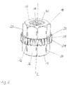
- figure 1 shows a first preferred embodiment of the threaded insert, while in figure 2 an axial sectional view of this thread insert is shown.
- This threaded insert comprises a cylindrical base body 10 which extends along its longitudinal axis L.
- This base body 10 has a first axial end 12 and a second axial end 14 .
- a central bore 40 is provided in the base body 10 .
- a thread is therefore arranged on a radial inner side 16 of the base body 10 .
- the connection insert can be equipped with a bayonet lock, a latching mechanism or a latching structure or with another connection construction.
- the base body instead of a bore with an internal thread, has an axial extension 50 which is arranged on the first 12 or second end 14 (see below). Since the extension 50 is provided with a connection contour 52, preferably a thread 52, a connection is made via the threaded bolt now present instead of via the internal thread.
- the preferred thread insert and its properties are exemplary for the structure, the function, the use and the production of connection inserts according to the invention.
- the cylindrical base body 10 is delimited in the axial direction by the first 12 and the second end 14 . It is preferably uniform in diameter, graduated or tapered or widened over its length. This applies both to a threaded insert with an internal thread 42 and to a connection insert with an axial extension 50.
- At least one radially circumferential collar 20 is arranged on a radial outer side 18 of the base body 10 . Compared to the rest of the base body 10, this collar 20 has the largest outside diameter. In addition, the collar 20 is not arranged on the first axial end 12 or on the second axial end 14 of the base body 10 . Rather, the collar 20 is in a central arrangement based on the length of the base body 10. According to a Figures 5 and 6 In the preferred embodiment of the present invention shown, collar 20 is positioned off-center with respect to the length of body 10 . At the same time, however, the collar 20 is at a distance from the first axial end 12 and from the second axial end 14 , so that the collar 20 does not form the axial termination of the base body 10 .
- a plurality of collars 20 are arranged on the radially outer side 18 of the base body 10 . While only one collar 20 preferably has an axial width of 10% to 60% of a total length of the base body 10, the same applies to the added axial widths of a plurality of collars arranged on the radial outside 18.
- the base body 10 comprises a radially projecting structure 30 on its radial outside 18.
- This structure 30 preferably runs in the axial direction of the base body 10.
- the structure 30 extends over the complete area between the collar 20 and the first axial end 12 and/or the second axial end 14 of the base body 10. It is also preferred that the structure 30 extends only in partial areas between the collar 20 and the first 12 and/or second axial end 14.
- the structure 30 is continuous in the areas described above, as shown in FIGS Figures 1 to 6 can be seen.
- the structure between the collar 20 and the first 12 and/or second axial end 14 is perforated. It follows that the preferred ridges 34 and indentations 36 running in the axial direction are continuous or interrupted or discontinuous between the collar 20 and the first 12 and/or the second axial end 14 .
- a circumferentially arranged knurling 32 is provided as the structure 30 .
- This knurling 32 consists of alternating ridges 34 and valleys 36, with the ridges 34 and valleys 36 preferably having an angular, rounded or curvilinear cross-sectional shape (not shown).
- the figures 1 and 2 show a preferred serrated knurling 32, while in figure 3 a torx-shaped knurling is provided as structure 30 .
- the collar 20 has an alternating arrangement of valleys 22 and elevations 24 in relation to their radial extension.
- the elevations 24 in particular form a pull-out safeguard in the axial direction of the base body 10. This pull-out safeguard acts in both axial directions, so that the threaded insert is secured against tensile and compressive loads in the axial direction.
- the collar 20 in general and the elevations 24 in particular thus form an axial undercut, the effect of which is further supported by the formation of the axial side surfaces 26 of the collar 20 .
- the side faces 26 preferably enclose an angle of at most 90° with the longitudinal axis L of the base body 10 . According to a further preferred embodiment, this angle is less than 90°.
- ⁇ 1 and ⁇ 2 designates the angle between the side surface 26, which faces the first axial end 12, and the longitudinal axis L of the base body.
- ⁇ 2 denotes the angle between the side surface 26, which faces the second axial end 14, and the longitudinal axis L of the base body 10.
- ⁇ 1 and ⁇ 2 can be the same size or different sizes. According to different preferred embodiments, the angles have a size of 90° ⁇ 1 , ⁇ 2 ⁇ 65°, more preferably 80° ⁇ 1 , ⁇ 2 ⁇ 70°. In the preferred embodiments of the figures 2 and 4 the angles ⁇ 1 and ⁇ 2 are of the same size and acute-angled.
- the peaks 24 and the valleys 22 are shaped differently. They are preferably sawtooth-like in accordance with figure 3 or flattened and concave according to figure 1 or generally angular, rounded or curvilinear in radial cross-section. While the shape of the collar 20 with the elevations 24 and the valleys 22 can vary, the functionality of the collar, which varies in diameter, must be ensured. This is because during embedding according to step S1 (see below), the elevations 24 cause plasticized plastic to accumulate on the collar 20 counter to the direction of embedding. This accumulation ensures that there is sufficient plasticized plastic that fills the structure 30 and the space between the side surface 26 and the radial outside 18 of the base body 10 in the angular range ⁇ 2 .
- the valleys 22 preferably allow the accumulated plastic to overflow sufficiently over the collar 20.
- This overflowing plastic is used to fill the structure 30 on the other side of the collar 20 and the angular area between the side surface 26 and the radial outside 18 of the base body 10 in the Angular range ⁇ 1 to be filled.
- the structure 30 preferably runs in the axial direction of the base body 10, this supports the flow of the plastic into the depressions 26.
- connection insert is in the Figures 7 and 8 shown.
- the connecting insert also includes the cylindrical base body 10 with the first 12 and second axial end 14.
- This base body 10 has the same features in its external design as those described above in general and/or with reference to the embodiments of FIG Figures 1 to 6 have been explained.
- connection insert in contrast to the thread insert, the connection insert according to Figures 7 and 8 a bolt-like axial extension 50 at its first axial end 12.
- the extension 50 preferably has a smaller diameter than the base body 10 and the collar 20. It is also preferred to provide the diameter of the extension 50 equal to or larger than the outside diameter of the base body 10 and/or the collar 20 .
- the base body 10 thus transitions into the extension 50 in a stepped manner at its axial end 12, with a continuous transition also being able to be implemented as an alternative.
- the extension 50 has a cylindrical, a conical, a stepped shape over its length or another shape (not shown).
- connection insert with extension 50 is integrally formed. It is also preferred that the connection insert is formed in two parts, in that the axial extension 50 is fixed in an inner opening of the connection insert, preferably screwed, glued, shrunk or otherwise fixed therein. According to a further preferred embodiment, the connection insert with extension 50 comprises an axial through-hole in order to realize a fluid connection on a component via the connection insert, for example.
- the extension 50 preferably has a thread 52 on its radial outside.
- other connection contours or constructions can also be realized at this point, such as preferably a latching contour, a plug-in connection contour or a wedging contour.
- the extension 50 is measured in terms of its axial length, beginning with the first axial End 12 of the body 10 is adaptable to specific connection requirements.
- the extension 50 therefore preferably has a length in the range from 40% to 200%, preferably 60% to 120%, of a length of the base body 10 .
- step S1 the material of a preformed plastic component is plasticized in a selected embedding area.
- the plasticizing takes place by supplying heat, inductively or with the help of ultrasound based on known methods.
- step S2 the threaded insert is pressed in the axial direction into the plasticized embedding area of the plastic component.
- the pressing-in preferably takes place with the second axial end 14 of the base body 10 in front.
- this bore is blocked, for example with a suitable mandrel or other suitably shaped construction. In this way, the plasticized plastic only flows around the structures on the radial outside 18 of the threaded insert.
- step S4 plasticized plastic is accumulated at the elevations 24 of the collar 20 (step S4). It follows that while the threaded insert is being pressed into the plastic component, the collar 20 pushes plasticized plastic in front of it in the area of the elevations 24 . In the area of the radial valleys 22, the accumulated plasticized plastic overflows in step S3. In this way, the valleys 22 as overflow areas ensure that sufficient plasticized plastic flows into the structure 30 between the collar 20 and the first axial end 12 of the base body. Furthermore, these overflow areas ensure that sufficient plasticized plastic wets the side surfaces 26 that face the first axial end 12 of the base body 10 .
- the plasticized plastic flows into the structure 30, which is arranged on one side or both sides of the collar 20 (step S5).
- This plasticized plastic fills the depressions 36 of the structure 30 almost completely or completely, so that the Plastic forms an anti-twist device for the threaded insert about its longitudinal axis L after it has hardened.
- the accumulation of the plasticized plastic on the collar 20 and the overflowing of the plasticized plastic that has accumulated on the collar 20 causes the lateral surfaces 26 to be preferably completely wetted on both sides with the plasticized plastic.
- the hardened plastic Due to the angular arrangement of the side faces 26 of the collar 20 compared to the radial outside 18 of the base body 10, the hardened plastic preferably forms acute-angled undercuts on these side faces 26. These acute-angled undercuts secure the position of the threaded insert in the axial direction. This means that the threaded insert is secured both against being pulled out and against further pressing into the plastic body.
- connection insert can also be fastened in a component made of plastic or metal with the aid of a molding method.
- Molding processes include what are known as primary molding processes, with which a component can be produced from a plasticized material, such as plastic or metal.
- These primary shaping processes preferably include injection molding of plastic and casting of metal. The molding process is explained using the injection molding process as an example.
- connection insert is positioned in an injection mold (not shown). Depending on the design of the connector insert, the interior of the connector insert is blocked by a pin or the like to prevent ingress of plastic or other material.
- plasticized plastic is injected into the injection mold and the connection insert is thereby encapsulated in step E2. In general, this is a plasticized, settable material, as mentioned above, so that the connection insert is molded into the component.
- the injection mold has been sufficiently filled with plastic, it hardens in step E7 the overmolded material.
- the component with the connection insert is removed from the injection mold (step E8).
- the method steps E3 to E6 therefore correspond to the method steps S3 to S6 of the embedding method described above, the description of which is hereby referred to.
- a cylindrical base body made of metal is provided.
- the cylindrical body consists of a piece of wire that has been cut or sheared off an endless wire in step SII.
- This cylindrical body has first and second ends (not shown).
- This base body is then positioned with the first axial end in a first die and with the second axial end in a second die (step S III).
- the first and second dies together define an internal cavity that defines in whole or in part the external shape of the threaded insert described above.
- the defined cavity has a cylindrical shape with a peripheral recess for forming the collar 20 described above.
- collar 20 is formed in a dedicated cavity at the interface between the first and second dies. This arrangement of the cavity allows sufficient demolding of the Insert even when the collar 20 has acutely oriented side surfaces 26 with respect to the longitudinal axis L of the Insert.
- step S III After the base body has been positioned in the first and second dies (step S III), this is preferably done by moving the first and second dies towards one another Die an upsetting and / or extrusion of the first (step S IV) and the second end (step SV) of the base body 10. Due to these processes, a circumferential collar 20 is formed, which compared to the rest of the base body 10 has the largest outer diameter. At the same time, the collar 20 is arranged at a distance from the first axial end 12 and the second axial end 14 of the base body 10 .
- the structure 30 is also formed on the radial outside 18 of the base body during upsetting and/or extrusion by the movement of the first and second dies.
- a rolling or extrusion of a radially protruding structure which is arranged on the radial outside 18 of the base body 10, takes place in step S VI.
- This molded structure 30 also extends parallel to the longitudinal axis L of the base body 10.
- the bolt-like axial extension 50 adjoining the first axial end 12 of the base body 10 is shaped in step SVII.
- One of the connection contours 52 mentioned above can then be provided on the extension 50 .
Landscapes
- Engineering & Computer Science (AREA)
- Mechanical Engineering (AREA)
- General Engineering & Computer Science (AREA)
- Manufacturing & Machinery (AREA)
- Injection Moulding Of Plastics Or The Like (AREA)
Claims (20)
- Insert d'assemblage apte à être moulé dans une pièce en plastique et présentant les caractéristiques suivantes :a. un corps de base cylindrique (10) avec un côté extérieur radial (18) ainsi qu'une première (12) et une deuxième extrémité axiale (14),b. au moins une collerette périphérique (20) disposée sur le côté extérieur radial (18) du corps de base (10), laquelle présente au moins par endroits le plus grand diamètre extérieur en comparaison avec le reste du corps de base (10) et laquelle est disposée de façon espacée par rapport à la première (12) et à la deuxième extrémité axiale (14) du corps de base (10),c. une structure faisant saillie radialement (30) sur le côté extérieur radial (18) du corps de base (10), laquelle s'étend de façon continue et/ou discontinue parallèlement et/ou obliquement à l'axe longitudinal (L) du corps de base (10), entre la collerette (20) et la première (12) et/ou la deuxième extrémité axiale (14), dans lequeld. la collerette (20) présente un diamètre variable dans une direction d'extension périphérique, de sorte qu'une pluralité de creux (22) et de reliefs (24) radiaux sont disposés dans la collerette (20), ete. le corps de base cylindrique (10) présente un alésage central (40) avec un côté intérieur radial, sur lequel est prévue une structure d'assemblage, de préférence un filetage (42), une fermeture à baïonnette ou un moletage radial, ouf. le corps de base cylindrique (10) présente une saillie axiale du genre boulon (50) au niveau de la première extrémité axiale (12).
- Insert d'assemblage selon la revendication 1, dont la collerette (20) est limitée par deux surfaces latérales (26) dans la direction axiale du corps de base, lesquelles forment au moins par endroits respectivement un angle de 90° maximum avec l'axe longitudinal (L) du corps de base (10), en particulier un angle < 90°.
- Insert d'assemblage selon l'une des revendications précédentes, dont la structure faisant saillie radialement (30) est constituée d'un moletage (32) s'étendant parallèlement à l'axe longitudinal (L) du corps de base (10), lequel est disposé sur un côté ou sur les deux côtés de la collerette (20).
- Insert d'assemblage selon la revendication 3, dont le moletage (32) est constitué d'âmes (34) faisant saillie radialement tout en étant espacées entre elles de façon régulière, lesquelles présentent une forme de section transversale angulaire, arrondie ou curviligne.
- Insert d'assemblage selon l'une des revendications précédentes, dont l'au moins une collerette (20) est disposée de façon axialement centrale et/ou de façon adjacente aux extrémités axiales (12, 14).
- Insert d'assemblage selon l'une des revendications précédentes, dont la collerette (10) ou dont la pluralité de collerettes présente(-nt) conjointement une largeur axiale mesurant de 10% à 60% d'une longueur totale du corps de base (10), de préférence de 20% à 40%.
- Insert d'assemblage selon la revendication 1, dans lequel le corps de base cylindrique (10) présente une saillie axiale du genre boulon (50) au niveau de la première extrémité axiale (12), et la saillie (50) est décalée de façon étagée par rapport au corps de base (10) et/ou présente de préférence une longueur comprise entre 40% et 200% d'une longueur du corps de base (10).
- Insert d'assemblage selon la revendication 1, dans lequel le corps de base cylindrique (10) présente une saillie axiale du genre boulon (50) au niveau de la première extrémité axiale (12), ou selon la revendication 7, dont la saillie (50) est un boulon d'assemblage avec un filetage extérieur (52) ou un contour d'encliquetage ou un contour d'assemblage par enfichage.
- Procédé d'inclusion pour un insert d'assemblage selon l'une des revendications précédentes, présentant les étapes suivantes :a. plastification (S1) de matériau dans une région d'inclusion d'une pièce en plastique moulée,b. pressage (S2) de l'insert d'assemblage dans la direction axiale dans la région d'inclusion, de telle façon que le matériau de la pièce en plastique s'accumule sur la collerette et recouvre au moins partiellement la collerette, de sorte que la collerette forme une sécurité anti-extraction axiale après le durcissement du matériau.
- Procédé d'inclusion selon la revendication 9, dans lequel la collerette de l'élément d'assemblage présente des creux et des reliefs radiaux, de sorte que pendant le pressage, le matériau plastifié recouvre la collerette (S3) au niveau des creux radiaux et s'accumule (S4) au niveau des reliefs.
- Procédé d'inclusion selon la revendication 9 ou 10, dans lequel le matériau plastifié s'écoule dans un moletage axial adjacente à la collerette (S5), de manière à former une sécurité antirotation après durcissement.
- Procédé d'inclusion selon la revendication 9, dans lequel le matériau plastifié recouvre (S6) respectivement une surface latérale axiale sur les deux côtés de la collerette, de sorte que le matériau plastifié forme une contre-dépouille à angle aigu en tant que sécurité anti-extraction axiale bilatérale après un durcissement.
- Procédé d'inclusion pour un insert d'assemblage selon l'une des revendications 1 à 8, présentant les étapes suivantes :a. positionnement (E1) de l'insert d'assemblage dans un moule, de préférence un moule à injection,b. enrobage, de préférence par injection (E2), de l'insert d'assemblage avec un matériau durcissable plastifié, l'insert d'assemblage étant moulé dans une pièce, etc. durcissement (E7) du matériau d'enrobage, de préférence injecté, et démoulage (E8) de la pièce avec l'insert d'assemblage hors du moule, de préférence du moule à injection.
- Procédé d'inclusion selon la revendication 13, dans lequel la collerette de l'insert d'assemblage présente des creux et des reliefs radiaux, de sorte que pendant l'enrobage, de préférence pendant l'enrobage par injection (E2), le matériau plastifié recouvre la collerette dans les creux radiaux (E3) et s'accumule sur les reliefs (E4).
- Procédé d'inclusion selon la revendication 13 ou 14, dans lequel le matériau plastifié s'écoule dans un moletage axial adjacent à la collerette (E5), de manière à former une sécurité antirotation après durcissement.
- Procédé d'inclusion selon la revendication 13, dans lequel le matériau plastifié recouvre respectivement surface latérale axiale sur les deux côtés de la collerette (E6), de sorte que le matériau plastifié forme une contre-dépouille à angle aigu en tant que sécurité anti-extraction axiale bilatérale après un durcissement.
- Procédé de fabrication d'un insert d'assemblage selon l'une des revendications 1 à 8, présentant les étapes suivantes :a. mise à disposition (SI) d'un corps de base cylindrique en métal, lequel présente une première et une deuxième extrémité,b. positionnement (SIII) du corps de base avec la première extrémité vers une première matrice et la deuxième extrémité vers une deuxième matrice,c. refoulement et/ou extrusion de la première (SIV) et de la deuxième extrémité (SV) du corps de base, de manière à former une collerette périphérique, laquelle présente le plus grand diamètre extérieur en comparaison avec le reste du corps de base et laquelle est disposée de façon espacée par rapport à la première et à la deuxième extrémité du corps de base etd. roulage ou extrusion (SVI) d'une structure faisant saillie radialement, laquelle est disposée sur un côté extérieur radial du corps de base et s'étend parallèlement à un axe longitudinal du corps de base.
- Procédé de fabrication selon la revendication 17, dans lequel un morceau de fil métallique est coupé à partir d'un fil métallique sans fin (SII).
- Procédé de fabrication selon l'une des revendications 17 à 18, comprenant l'étape supplémentaire suivante :- démoulage (SVII) d'une saillie axiale du genre boulon (50) prolongeant la première extrémité axiale (12) du corps de base (10).
- Pièce avec un insert d'assemblage selon l'une des revendications 1 à 8.
Applications Claiming Priority (2)
| Application Number | Priority Date | Filing Date | Title |
|---|---|---|---|
| DE102013217448.9A DE102013217448A1 (de) | 2013-09-02 | 2013-09-02 | Verbindungseinsatz sowie ein Einbettverfahren und ein Herstellungsverfahren dafür |
| PCT/EP2014/068572 WO2015028680A1 (fr) | 2013-09-02 | 2014-09-02 | Insert d'assemblage ainsi que procédé d'inclusion et procédé de fabrication correspondant |
Publications (3)
| Publication Number | Publication Date |
|---|---|
| EP3042090A1 EP3042090A1 (fr) | 2016-07-13 |
| EP3042090B1 true EP3042090B1 (fr) | 2022-07-06 |
| EP3042090B8 EP3042090B8 (fr) | 2022-08-31 |
Family
ID=51485601
Family Applications (1)
| Application Number | Title | Priority Date | Filing Date |
|---|---|---|---|
| EP14758867.7A Active EP3042090B8 (fr) | 2013-09-02 | 2014-09-02 | Insert d'assemblage ainsi que procédé d'inclusion et procédé de fabrication correspondant |
Country Status (5)
| Country | Link |
|---|---|
| US (1) | US9790981B2 (fr) |
| EP (1) | EP3042090B8 (fr) |
| CN (1) | CN105518318B (fr) |
| DE (1) | DE102013217448A1 (fr) |
| WO (1) | WO2015028680A1 (fr) |
Families Citing this family (10)
| Publication number | Priority date | Publication date | Assignee | Title |
|---|---|---|---|---|
| FR3037525B1 (fr) * | 2015-06-22 | 2017-12-29 | Valeo Systemes Thermiques | Element de fixation, ensemble comprenant ledit element de fixation, module de face avant comprenant ledit element de fixation et procede pour fixer ledit element de fixation |
| US10049813B2 (en) * | 2016-04-25 | 2018-08-14 | Borgwarner Inc. | Method of roll-forming with gap fillers for solenoid used for transmission |
| DE102016113920A1 (de) * | 2016-07-28 | 2018-02-01 | Man Diesel & Turbo Se | Exzenterbolzen |
| CN107877778A (zh) * | 2017-12-08 | 2018-04-06 | 蔡凡 | 一种陶瓷件上高精度结构的制备工艺及方法 |
| DE102018102045A1 (de) | 2018-01-30 | 2019-08-01 | Böllhoff Verbindungstechnik GmbH | Bauteil mit Toleranzausgleichsfunktion |
| DE102020205566A1 (de) | 2020-04-30 | 2021-11-04 | Berrang Entwicklungsgmbh | Metalleinsatz zur Verwendung in Kunststoffbauteilen |
| EP3915763B1 (fr) | 2020-05-25 | 2024-04-17 | Böllhoff Verbindungstechnik GmbH | Composant imprimé en 3d ainsi que procédé de fabrication associé |
| DE102021206773A1 (de) * | 2021-06-29 | 2022-12-29 | Osram Gmbh | Einlegeteil für die gas- und/oder flüssigkeitsdichte Umspritzung mit einem Kunststoff sowie Lampe für Fahrzeugleuchten mit dem Einlegeteil |
| CN115707880A (zh) * | 2021-08-19 | 2023-02-21 | 名硕电脑(苏州)有限公司 | 预埋防松螺母 |
| US20230287925A1 (en) * | 2022-03-10 | 2023-09-14 | Ewing-Foley, Inc. | Clinching sleeve fastener |
Citations (3)
| Publication number | Priority date | Publication date | Assignee | Title |
|---|---|---|---|---|
| US3125146A (en) * | 1964-03-17 | Sheet metal fasteners | ||
| DE2530882A1 (de) * | 1974-12-11 | 1976-06-16 | Vyzk Ustav Mech | Gewindeeinlage fuer kunststoffpresslinge |
| DE3016590A1 (de) * | 1980-04-30 | 1981-11-19 | Böllhof & Co, 4800 Bielefeld | Metallischer gewindeeinsatz zum einbau in werkstuecke aus thermoplatischem kunststoff unter thermischer erweichung des kunststoffmaterials |
Family Cites Families (34)
| Publication number | Priority date | Publication date | Assignee | Title |
|---|---|---|---|---|
| NL283819A (fr) * | 1958-06-24 | |||
| US3198231A (en) * | 1962-01-09 | 1965-08-03 | South Chester Corp | High strength threaded insert |
| GB1004562A (en) * | 1962-03-02 | 1965-09-15 | Walsh John & Co Inserts Ltd | Improvements in fasteners or bushes for anchoring in sheet material or the like |
| US3279303A (en) * | 1964-04-29 | 1966-10-18 | Goodrich Co B F | Two-part expansible fastener |
| US3281173A (en) * | 1965-01-08 | 1966-10-25 | Rosan Eng Corp | Insert having an integral locking collar |
| US3431960A (en) * | 1966-10-10 | 1969-03-11 | Robert Neuschotz | Threaded fastener with deformable anchoring portion |
| US3467417A (en) * | 1966-11-09 | 1969-09-16 | Standard Pressed Steel Co | Fastener unit |
| US3461936A (en) * | 1967-10-19 | 1969-08-19 | Robert D Weber | Self-retained tension nut |
| US3498353A (en) * | 1968-06-03 | 1970-03-03 | Southco | Press insert |
| DE2917934A1 (de) * | 1979-05-04 | 1980-11-13 | Precision Fasteners | Gewindeeinsatz |
| DE3315030A1 (de) * | 1983-04-26 | 1984-10-31 | Friedrichsfeld Gmbh, Steinzeug- Und Kunststoffwerke, 6800 Mannheim | Schraubmuffe |
| GB2167148B (en) * | 1984-11-15 | 1988-02-03 | Psm Fasteners Ltd | Inserts |
| US4729705A (en) * | 1987-02-02 | 1988-03-08 | Atr International, Inc. | Insert fastener in a lightweight panel |
| DE8809742U1 (fr) * | 1988-07-22 | 1988-10-06 | Rosenberg, Gerhard, 5952 Attendorn, De | |
| GB8818414D0 (en) * | 1988-08-03 | 1988-09-07 | Psm Int Plc | Improvements to screw threaded fasteners |
| DE3838250C1 (fr) | 1988-11-11 | 1990-01-18 | Dr.Ing.H.C. F. Porsche Ag, 7000 Stuttgart, De | |
| US5366257A (en) * | 1992-12-30 | 1994-11-22 | Eslon Thermoplastics, A Division Of Sekisui America Corporation | Pipe connector |
| US5445483A (en) * | 1993-08-23 | 1995-08-29 | Emhart Inc. | Female clinch fastener with cold-formed locking flange and associated installation method |
| US5673927A (en) * | 1994-08-25 | 1997-10-07 | Vermillion; James H. | Composite snowboard insert and method of installation |
| JPH08219360A (ja) * | 1995-02-08 | 1996-08-30 | Mitsubishi Plastics Ind Ltd | インサート継手 |
| DE10013091A1 (de) | 2000-03-17 | 2001-09-20 | Boellhoff Gmbh | Metallischer Einsatz mit Rippen |
| US6474918B1 (en) * | 2000-06-30 | 2002-11-05 | Ashton Plastic Products, Inc. | Anti-cross threading device |
| JP3775975B2 (ja) * | 2000-08-03 | 2006-05-17 | Smc株式会社 | 熱可塑性樹脂からなる基材への部品埋め込み方法 |
| US6676352B2 (en) | 2001-03-13 | 2004-01-13 | Ju-Ching Chen-Chi | Fasteners with improved retaining effect |
| US7004699B2 (en) * | 2001-09-25 | 2006-02-28 | Newfrey Llc | Quick assembly fastening system for plastic parts |
| DE10253448B4 (de) * | 2002-11-16 | 2016-02-18 | Bayerische Motoren Werke Aktiengesellschaft | Gewindeeinsatz |
| CN101808811A (zh) * | 2007-09-26 | 2010-08-18 | 富士通株式会社 | 嵌件的嵌入方法 |
| GB2460092B (en) * | 2008-05-16 | 2011-12-21 | Psm Ip Ltd | An insert kit and installation method |
| ES2483742T3 (es) | 2010-03-01 | 2014-08-07 | Illinois Tool Works Inc. | Rosca en forma de cascada para insertos |
| BR112012025378A2 (pt) | 2010-04-16 | 2016-06-28 | Illinois Tool Works | inserção espiral com entalhe de haste de anel |
| US9080593B2 (en) | 2010-04-16 | 2015-07-14 | Illinois Tool Works Inc. | Embeddable assembly |
| CN102418448A (zh) * | 2011-12-20 | 2012-04-18 | 陈俊 | 铆接装配定位轴及采用该铆接装配定位轴的一体式摇窗器 |
| CN102570115B (zh) * | 2012-02-28 | 2014-05-21 | 深圳市簧中簧电子有限公司 | 一种插座导体和插座系统 |
| CN203081968U (zh) * | 2012-12-19 | 2013-07-24 | 上海汽车制动器有限公司 | 一种改进结构的前壳体螺钉 |
-
2013
- 2013-09-02 DE DE102013217448.9A patent/DE102013217448A1/de not_active Withdrawn
-
2014
- 2014-09-02 WO PCT/EP2014/068572 patent/WO2015028680A1/fr active Application Filing
- 2014-09-02 EP EP14758867.7A patent/EP3042090B8/fr active Active
- 2014-09-02 CN CN201480048482.6A patent/CN105518318B/zh active Active
- 2014-09-02 US US14/915,953 patent/US9790981B2/en active Active
Patent Citations (3)
| Publication number | Priority date | Publication date | Assignee | Title |
|---|---|---|---|---|
| US3125146A (en) * | 1964-03-17 | Sheet metal fasteners | ||
| DE2530882A1 (de) * | 1974-12-11 | 1976-06-16 | Vyzk Ustav Mech | Gewindeeinlage fuer kunststoffpresslinge |
| DE3016590A1 (de) * | 1980-04-30 | 1981-11-19 | Böllhof & Co, 4800 Bielefeld | Metallischer gewindeeinsatz zum einbau in werkstuecke aus thermoplatischem kunststoff unter thermischer erweichung des kunststoffmaterials |
Also Published As
| Publication number | Publication date |
|---|---|
| US20160195124A1 (en) | 2016-07-07 |
| EP3042090B8 (fr) | 2022-08-31 |
| WO2015028680A1 (fr) | 2015-03-05 |
| CN105518318A (zh) | 2016-04-20 |
| DE102013217448A1 (de) | 2015-03-05 |
| EP3042090A1 (fr) | 2016-07-13 |
| CN105518318B (zh) | 2018-07-13 |
| US9790981B2 (en) | 2017-10-17 |
Similar Documents
| Publication | Publication Date | Title |
|---|---|---|
| EP3042090B1 (fr) | Insert d'assemblage ainsi que procédé d'inclusion et procédé de fabrication correspondant | |
| EP2483569B1 (fr) | Insert de filetage en fil métallique conformable, procédé de fabrication correspondant, composant pourvu d'un tel insert de filetage en fil métallique conformable, et procédé de fabrication correspondant | |
| EP1010901A1 (fr) | Douille métallique | |
| DE102017214518A1 (de) | Verbundgussteil und Verfahren zum Herstellen eines Verbundgussteils | |
| EP2213893A1 (fr) | Cage de palier de roulement constitué d'un pluralité d'éléments | |
| EP3405686B1 (fr) | Elément fileté en plastique et dispositif de raccordement constitué d'une pièce de support en plastique et d'un élément fileté en plastique | |
| EP2595785B1 (fr) | Pièce moulée par injection et procédé de moulage par injection | |
| EP3131727B1 (fr) | Vis cylindrique creuse avec renforcement dans son filetage et son procédé de fabrication | |
| DE202008000574U9 (de) | Verbindungseinrichtung | |
| EP3701157B1 (fr) | Produit semi-fini pour la fabrication d'un élément composite renforcé de fibres présentant un trou de fixation ou une partie saillante de fixation, élément composite et procédé de fabrication d'un élément composite | |
| DE10334898B4 (de) | Halteelement zur Fixierung wenigstens eines Lagers | |
| EP1872020B1 (fr) | Cheville pour ancrage dans des materiaux de construction en dur | |
| EP3219442A1 (fr) | Élement d'entrainement d'un couple de rotation sur une cosse a insert filete | |
| DE102011011215B4 (de) | Verfahren zum Verbinden und Verbindung eines ersten Werkstückes mit einem zweiten Werkstück | |
| EP0457126B1 (fr) | Collecteur pour moteur ou générateur électrique | |
| DE202009017299U1 (de) | Fluidarmatur | |
| DE102006010148A1 (de) | Verfahren zum Herstellen eines Faserverbundkunststoff-Formteils und Fügeelement | |
| DE102017111697A1 (de) | Lageranordnung | |
| WO2020178430A9 (fr) | Pièce hybride et procédé de production d'une pièce hybride | |
| DE202019104970U1 (de) | Kugelbolzen | |
| DE3432461C2 (fr) | ||
| DE202017103877U1 (de) | Verbindungsanker sowie Beton-Sandwich-Platte mit derartigen Verbindungsankern | |
| DE8104809U1 (de) | Aus Kunststoff bestehendes einstückiges Lagergehäuse | |
| DE3321273A1 (de) | Schutzvorrichtung fuer das ende eines mit innen- oder aussengewinde versehenen rohres und verfahren zur herstellung einer schutzvorrichtung | |
| EP1159535B1 (fr) | Cheville a expansion |
Legal Events
| Date | Code | Title | Description |
|---|---|---|---|
| PUAI | Public reference made under article 153(3) epc to a published international application that has entered the european phase |
Free format text: ORIGINAL CODE: 0009012 |
|
| 17P | Request for examination filed |
Effective date: 20160218 |
|
| AK | Designated contracting states |
Kind code of ref document: A1 Designated state(s): AL AT BE BG CH CY CZ DE DK EE ES FI FR GB GR HR HU IE IS IT LI LT LU LV MC MK MT NL NO PL PT RO RS SE SI SK SM TR |
|
| AX | Request for extension of the european patent |
Extension state: BA ME |
|
| RIN1 | Information on inventor provided before grant (corrected) |
Inventor name: CHALVET, FRANCK Inventor name: PERROUD, NORBERT Inventor name: RAHAL, MOHAMED-TAHAR Inventor name: STUMPF, MICHAEL |
|
| DAX | Request for extension of the european patent (deleted) | ||
| STAA | Information on the status of an ep patent application or granted ep patent |
Free format text: STATUS: EXAMINATION IS IN PROGRESS |
|
| 17Q | First examination report despatched |
Effective date: 20190411 |
|
| STAA | Information on the status of an ep patent application or granted ep patent |
Free format text: STATUS: EXAMINATION IS IN PROGRESS |
|
| GRAP | Despatch of communication of intention to grant a patent |
Free format text: ORIGINAL CODE: EPIDOSNIGR1 |
|
| STAA | Information on the status of an ep patent application or granted ep patent |
Free format text: STATUS: GRANT OF PATENT IS INTENDED |
|
| INTG | Intention to grant announced |
Effective date: 20220120 |
|
| GRAJ | Information related to disapproval of communication of intention to grant by the applicant or resumption of examination proceedings by the epo deleted |
Free format text: ORIGINAL CODE: EPIDOSDIGR1 |
|
| STAA | Information on the status of an ep patent application or granted ep patent |
Free format text: STATUS: EXAMINATION IS IN PROGRESS |
|
| GRAS | Grant fee paid |
Free format text: ORIGINAL CODE: EPIDOSNIGR3 |
|
| STAA | Information on the status of an ep patent application or granted ep patent |
Free format text: STATUS: GRANT OF PATENT IS INTENDED |
|
| GRAP | Despatch of communication of intention to grant a patent |
Free format text: ORIGINAL CODE: EPIDOSNIGR1 |
|
| INTC | Intention to grant announced (deleted) | ||
| GRAA | (expected) grant |
Free format text: ORIGINAL CODE: 0009210 |
|
| STAA | Information on the status of an ep patent application or granted ep patent |
Free format text: STATUS: THE PATENT HAS BEEN GRANTED |
|
| INTG | Intention to grant announced |
Effective date: 20220519 |
|
| AK | Designated contracting states |
Kind code of ref document: B1 Designated state(s): AL AT BE BG CH CY CZ DE DK EE ES FI FR GB GR HR HU IE IS IT LI LT LU LV MC MK MT NL NO PL PT RO RS SE SI SK SM TR |
|
| REG | Reference to a national code |
Ref country code: GB Ref legal event code: FG4D Free format text: NOT ENGLISH |
|
| REG | Reference to a national code |
Ref country code: AT Ref legal event code: REF Ref document number: 1503067 Country of ref document: AT Kind code of ref document: T Effective date: 20220715 Ref country code: CH Ref legal event code: EP |
|
| GRAT | Correction requested after decision to grant or after decision to maintain patent in amended form |
Free format text: ORIGINAL CODE: EPIDOSNCDEC |
|
| REG | Reference to a national code |
Ref country code: DE Ref legal event code: R096 Ref document number: 502014016311 Country of ref document: DE |
|
| GRAE | Information related to correction after decision to grant or after decision to maintain patent in amended form modified |
Free format text: ORIGINAL CODE: EPIDOSCCDEC |
|
| REG | Reference to a national code |
Ref country code: IE Ref legal event code: FG4D Free format text: LANGUAGE OF EP DOCUMENT: GERMAN |
|
| REG | Reference to a national code |
Ref country code: DE Ref legal event code: R083 Ref document number: 502014016311 Country of ref document: DE |
|
| REG | Reference to a national code |
Ref country code: CH Ref legal event code: PK Free format text: BERICHTIGUNGEN Ref country code: CH Ref legal event code: PK Free format text: BERICHTIGUNG B8 |
|
| RIN2 | Information on inventor provided after grant (corrected) |
Inventor name: PERROUD, NORBERT Inventor name: RAHAL, MOHAMED-TAHAR Inventor name: CHALVET, FRANCK Inventor name: STUMPF, MICHAEL |
|
| RIN2 | Information on inventor provided after grant (corrected) |
Inventor name: PERROUD, NORBERT Inventor name: RAHAL, MOHAMED-TAHAR Inventor name: CHALVET, FRANCK Inventor name: STUMPF, MICHAEL |
|
| REG | Reference to a national code |
Ref country code: LT Ref legal event code: MG9D |
|
| REG | Reference to a national code |
Ref country code: NL Ref legal event code: MP Effective date: 20220706 |
|
| PG25 | Lapsed in a contracting state [announced via postgrant information from national office to epo] |
Ref country code: SE Free format text: LAPSE BECAUSE OF FAILURE TO SUBMIT A TRANSLATION OF THE DESCRIPTION OR TO PAY THE FEE WITHIN THE PRESCRIBED TIME-LIMIT Effective date: 20220706 Ref country code: RS Free format text: LAPSE BECAUSE OF FAILURE TO SUBMIT A TRANSLATION OF THE DESCRIPTION OR TO PAY THE FEE WITHIN THE PRESCRIBED TIME-LIMIT Effective date: 20220706 Ref country code: PT Free format text: LAPSE BECAUSE OF FAILURE TO SUBMIT A TRANSLATION OF THE DESCRIPTION OR TO PAY THE FEE WITHIN THE PRESCRIBED TIME-LIMIT Effective date: 20221107 Ref country code: NO Free format text: LAPSE BECAUSE OF FAILURE TO SUBMIT A TRANSLATION OF THE DESCRIPTION OR TO PAY THE FEE WITHIN THE PRESCRIBED TIME-LIMIT Effective date: 20221006 Ref country code: NL Free format text: LAPSE BECAUSE OF FAILURE TO SUBMIT A TRANSLATION OF THE DESCRIPTION OR TO PAY THE FEE WITHIN THE PRESCRIBED TIME-LIMIT Effective date: 20220706 Ref country code: LV Free format text: LAPSE BECAUSE OF FAILURE TO SUBMIT A TRANSLATION OF THE DESCRIPTION OR TO PAY THE FEE WITHIN THE PRESCRIBED TIME-LIMIT Effective date: 20220706 Ref country code: LT Free format text: LAPSE BECAUSE OF FAILURE TO SUBMIT A TRANSLATION OF THE DESCRIPTION OR TO PAY THE FEE WITHIN THE PRESCRIBED TIME-LIMIT Effective date: 20220706 Ref country code: FI Free format text: LAPSE BECAUSE OF FAILURE TO SUBMIT A TRANSLATION OF THE DESCRIPTION OR TO PAY THE FEE WITHIN THE PRESCRIBED TIME-LIMIT Effective date: 20220706 Ref country code: ES Free format text: LAPSE BECAUSE OF FAILURE TO SUBMIT A TRANSLATION OF THE DESCRIPTION OR TO PAY THE FEE WITHIN THE PRESCRIBED TIME-LIMIT Effective date: 20220706 |
|
| PG25 | Lapsed in a contracting state [announced via postgrant information from national office to epo] |
Ref country code: PL Free format text: LAPSE BECAUSE OF FAILURE TO SUBMIT A TRANSLATION OF THE DESCRIPTION OR TO PAY THE FEE WITHIN THE PRESCRIBED TIME-LIMIT Effective date: 20220706 Ref country code: IS Free format text: LAPSE BECAUSE OF FAILURE TO SUBMIT A TRANSLATION OF THE DESCRIPTION OR TO PAY THE FEE WITHIN THE PRESCRIBED TIME-LIMIT Effective date: 20221106 Ref country code: HR Free format text: LAPSE BECAUSE OF FAILURE TO SUBMIT A TRANSLATION OF THE DESCRIPTION OR TO PAY THE FEE WITHIN THE PRESCRIBED TIME-LIMIT Effective date: 20220706 Ref country code: GR Free format text: LAPSE BECAUSE OF FAILURE TO SUBMIT A TRANSLATION OF THE DESCRIPTION OR TO PAY THE FEE WITHIN THE PRESCRIBED TIME-LIMIT Effective date: 20221007 |
|
| REG | Reference to a national code |
Ref country code: DE Ref legal event code: R097 Ref document number: 502014016311 Country of ref document: DE |
|
| PG25 | Lapsed in a contracting state [announced via postgrant information from national office to epo] |
Ref country code: SM Free format text: LAPSE BECAUSE OF FAILURE TO SUBMIT A TRANSLATION OF THE DESCRIPTION OR TO PAY THE FEE WITHIN THE PRESCRIBED TIME-LIMIT Effective date: 20220706 Ref country code: RO Free format text: LAPSE BECAUSE OF FAILURE TO SUBMIT A TRANSLATION OF THE DESCRIPTION OR TO PAY THE FEE WITHIN THE PRESCRIBED TIME-LIMIT Effective date: 20220706 Ref country code: MC Free format text: LAPSE BECAUSE OF FAILURE TO SUBMIT A TRANSLATION OF THE DESCRIPTION OR TO PAY THE FEE WITHIN THE PRESCRIBED TIME-LIMIT Effective date: 20220706 Ref country code: DK Free format text: LAPSE BECAUSE OF FAILURE TO SUBMIT A TRANSLATION OF THE DESCRIPTION OR TO PAY THE FEE WITHIN THE PRESCRIBED TIME-LIMIT Effective date: 20220706 Ref country code: CZ Free format text: LAPSE BECAUSE OF FAILURE TO SUBMIT A TRANSLATION OF THE DESCRIPTION OR TO PAY THE FEE WITHIN THE PRESCRIBED TIME-LIMIT Effective date: 20220706 |
|
| REG | Reference to a national code |
Ref country code: CH Ref legal event code: PL |
|
| PLBE | No opposition filed within time limit |
Free format text: ORIGINAL CODE: 0009261 |
|
| STAA | Information on the status of an ep patent application or granted ep patent |
Free format text: STATUS: NO OPPOSITION FILED WITHIN TIME LIMIT |
|
| REG | Reference to a national code |
Ref country code: BE Ref legal event code: MM Effective date: 20220930 |
|
| PG25 | Lapsed in a contracting state [announced via postgrant information from national office to epo] |
Ref country code: SK Free format text: LAPSE BECAUSE OF FAILURE TO SUBMIT A TRANSLATION OF THE DESCRIPTION OR TO PAY THE FEE WITHIN THE PRESCRIBED TIME-LIMIT Effective date: 20220706 Ref country code: EE Free format text: LAPSE BECAUSE OF FAILURE TO SUBMIT A TRANSLATION OF THE DESCRIPTION OR TO PAY THE FEE WITHIN THE PRESCRIBED TIME-LIMIT Effective date: 20220706 |
|
| 26N | No opposition filed |
Effective date: 20230411 |
|
| PG25 | Lapsed in a contracting state [announced via postgrant information from national office to epo] |
Ref country code: LU Free format text: LAPSE BECAUSE OF NON-PAYMENT OF DUE FEES Effective date: 20220902 Ref country code: AL Free format text: LAPSE BECAUSE OF FAILURE TO SUBMIT A TRANSLATION OF THE DESCRIPTION OR TO PAY THE FEE WITHIN THE PRESCRIBED TIME-LIMIT Effective date: 20220706 |
|
| PG25 | Lapsed in a contracting state [announced via postgrant information from national office to epo] |
Ref country code: LI Free format text: LAPSE BECAUSE OF NON-PAYMENT OF DUE FEES Effective date: 20220930 Ref country code: IE Free format text: LAPSE BECAUSE OF NON-PAYMENT OF DUE FEES Effective date: 20220902 Ref country code: CH Free format text: LAPSE BECAUSE OF NON-PAYMENT OF DUE FEES Effective date: 20220930 |
|
| PG25 | Lapsed in a contracting state [announced via postgrant information from national office to epo] |
Ref country code: SI Free format text: LAPSE BECAUSE OF FAILURE TO SUBMIT A TRANSLATION OF THE DESCRIPTION OR TO PAY THE FEE WITHIN THE PRESCRIBED TIME-LIMIT Effective date: 20220706 |
|
| PG25 | Lapsed in a contracting state [announced via postgrant information from national office to epo] |
Ref country code: BE Free format text: LAPSE BECAUSE OF NON-PAYMENT OF DUE FEES Effective date: 20220930 |
|
| PGFP | Annual fee paid to national office [announced via postgrant information from national office to epo] |
Ref country code: GB Payment date: 20230921 Year of fee payment: 10 |
|
| REG | Reference to a national code |
Ref country code: AT Ref legal event code: MM01 Ref document number: 1503067 Country of ref document: AT Kind code of ref document: T Effective date: 20220902 |
|
| PGFP | Annual fee paid to national office [announced via postgrant information from national office to epo] |
Ref country code: FR Payment date: 20230918 Year of fee payment: 10 |
|
| PG25 | Lapsed in a contracting state [announced via postgrant information from national office to epo] |
Ref country code: IT Free format text: LAPSE BECAUSE OF FAILURE TO SUBMIT A TRANSLATION OF THE DESCRIPTION OR TO PAY THE FEE WITHIN THE PRESCRIBED TIME-LIMIT Effective date: 20220706 Ref country code: AT Free format text: LAPSE BECAUSE OF NON-PAYMENT OF DUE FEES Effective date: 20220902 |
|
| PGFP | Annual fee paid to national office [announced via postgrant information from national office to epo] |
Ref country code: DE Payment date: 20231123 Year of fee payment: 10 |
|
| PG25 | Lapsed in a contracting state [announced via postgrant information from national office to epo] |
Ref country code: HU Free format text: LAPSE BECAUSE OF FAILURE TO SUBMIT A TRANSLATION OF THE DESCRIPTION OR TO PAY THE FEE WITHIN THE PRESCRIBED TIME-LIMIT; INVALID AB INITIO Effective date: 20140902 |
|
| PG25 | Lapsed in a contracting state [announced via postgrant information from national office to epo] |
Ref country code: CY Free format text: LAPSE BECAUSE OF FAILURE TO SUBMIT A TRANSLATION OF THE DESCRIPTION OR TO PAY THE FEE WITHIN THE PRESCRIBED TIME-LIMIT Effective date: 20220706 |