EP3042018B1 - Antriebsvorrichtung für die luke eines kraftfahrzeugs - Google Patents
Antriebsvorrichtung für die luke eines kraftfahrzeugs Download PDFInfo
- Publication number
- EP3042018B1 EP3042018B1 EP14748152.7A EP14748152A EP3042018B1 EP 3042018 B1 EP3042018 B1 EP 3042018B1 EP 14748152 A EP14748152 A EP 14748152A EP 3042018 B1 EP3042018 B1 EP 3042018B1
- Authority
- EP
- European Patent Office
- Prior art keywords
- drive
- drive device
- hatch
- motion
- arrangement
- Prior art date
- Legal status (The legal status is an assumption and is not a legal conclusion. Google has not performed a legal analysis and makes no representation as to the accuracy of the status listed.)
- Active
Links
Images


Classifications
-
- E—FIXED CONSTRUCTIONS
- E05—LOCKS; KEYS; WINDOW OR DOOR FITTINGS; SAFES
- E05F—DEVICES FOR MOVING WINGS INTO OPEN OR CLOSED POSITION; CHECKS FOR WINGS; WING FITTINGS NOT OTHERWISE PROVIDED FOR, CONCERNED WITH THE FUNCTIONING OF THE WING
- E05F1/00—Closers or openers for wings, not otherwise provided for in this subclass
- E05F1/08—Closers or openers for wings, not otherwise provided for in this subclass spring-actuated, e.g. for horizontally sliding wings
- E05F1/10—Closers or openers for wings, not otherwise provided for in this subclass spring-actuated, e.g. for horizontally sliding wings for swinging wings, e.g. counterbalance
- E05F1/1041—Closers or openers for wings, not otherwise provided for in this subclass spring-actuated, e.g. for horizontally sliding wings for swinging wings, e.g. counterbalance with a coil spring perpendicular to the pivot axis
- E05F1/105—Closers or openers for wings, not otherwise provided for in this subclass spring-actuated, e.g. for horizontally sliding wings for swinging wings, e.g. counterbalance with a coil spring perpendicular to the pivot axis with a compression spring
-
- E—FIXED CONSTRUCTIONS
- E05—LOCKS; KEYS; WINDOW OR DOOR FITTINGS; SAFES
- E05F—DEVICES FOR MOVING WINGS INTO OPEN OR CLOSED POSITION; CHECKS FOR WINGS; WING FITTINGS NOT OTHERWISE PROVIDED FOR, CONCERNED WITH THE FUNCTIONING OF THE WING
- E05F15/00—Power-operated mechanisms for wings
- E05F15/60—Power-operated mechanisms for wings using electrical actuators
- E05F15/603—Power-operated mechanisms for wings using electrical actuators using rotary electromotors
- E05F15/611—Power-operated mechanisms for wings using electrical actuators using rotary electromotors for swinging wings
- E05F15/616—Power-operated mechanisms for wings using electrical actuators using rotary electromotors for swinging wings operated by push-pull mechanisms
- E05F15/622—Power-operated mechanisms for wings using electrical actuators using rotary electromotors for swinging wings operated by push-pull mechanisms using screw-and-nut mechanisms
-
- F—MECHANICAL ENGINEERING; LIGHTING; HEATING; WEAPONS; BLASTING
- F16—ENGINEERING ELEMENTS AND UNITS; GENERAL MEASURES FOR PRODUCING AND MAINTAINING EFFECTIVE FUNCTIONING OF MACHINES OR INSTALLATIONS; THERMAL INSULATION IN GENERAL
- F16H—GEARING
- F16H25/00—Gearings comprising primarily only cams, cam-followers and screw-and-nut mechanisms
- F16H25/18—Gearings comprising primarily only cams, cam-followers and screw-and-nut mechanisms for conveying or interconverting oscillating or reciprocating motions
- F16H25/20—Screw mechanisms
-
- H—ELECTRICITY
- H02—GENERATION; CONVERSION OR DISTRIBUTION OF ELECTRIC POWER
- H02K—DYNAMO-ELECTRIC MACHINES
- H02K7/00—Arrangements for handling mechanical energy structurally associated with dynamo-electric machines, e.g. structural association with mechanical driving motors or auxiliary dynamo-electric machines
- H02K7/10—Structural association with clutches, brakes, gears, pulleys or mechanical starters
-
- E—FIXED CONSTRUCTIONS
- E05—LOCKS; KEYS; WINDOW OR DOOR FITTINGS; SAFES
- E05F—DEVICES FOR MOVING WINGS INTO OPEN OR CLOSED POSITION; CHECKS FOR WINGS; WING FITTINGS NOT OTHERWISE PROVIDED FOR, CONCERNED WITH THE FUNCTIONING OF THE WING
- E05F15/00—Power-operated mechanisms for wings
- E05F15/60—Power-operated mechanisms for wings using electrical actuators
- E05F15/603—Power-operated mechanisms for wings using electrical actuators using rotary electromotors
- E05F15/611—Power-operated mechanisms for wings using electrical actuators using rotary electromotors for swinging wings
-
- E—FIXED CONSTRUCTIONS
- E05—LOCKS; KEYS; WINDOW OR DOOR FITTINGS; SAFES
- E05Y—INDEXING SCHEME ASSOCIATED WITH SUBCLASSES E05D AND E05F, RELATING TO CONSTRUCTION ELEMENTS, ELECTRIC CONTROL, POWER SUPPLY, POWER SIGNAL OR TRANSMISSION, USER INTERFACES, MOUNTING OR COUPLING, DETAILS, ACCESSORIES, AUXILIARY OPERATIONS NOT OTHERWISE PROVIDED FOR, APPLICATION THEREOF
- E05Y2201/00—Constructional elements; Accessories therefor
- E05Y2201/20—Brakes; Disengaging means; Holders; Stops; Valves; Accessories therefor
- E05Y2201/21—Brakes
-
- E—FIXED CONSTRUCTIONS
- E05—LOCKS; KEYS; WINDOW OR DOOR FITTINGS; SAFES
- E05Y—INDEXING SCHEME ASSOCIATED WITH SUBCLASSES E05D AND E05F, RELATING TO CONSTRUCTION ELEMENTS, ELECTRIC CONTROL, POWER SUPPLY, POWER SIGNAL OR TRANSMISSION, USER INTERFACES, MOUNTING OR COUPLING, DETAILS, ACCESSORIES, AUXILIARY OPERATIONS NOT OTHERWISE PROVIDED FOR, APPLICATION THEREOF
- E05Y2800/00—Details, accessories and auxiliary operations not otherwise provided for
- E05Y2800/10—Additional functions
- E05Y2800/122—Telescopic action
-
- E—FIXED CONSTRUCTIONS
- E05—LOCKS; KEYS; WINDOW OR DOOR FITTINGS; SAFES
- E05Y—INDEXING SCHEME ASSOCIATED WITH SUBCLASSES E05D AND E05F, RELATING TO CONSTRUCTION ELEMENTS, ELECTRIC CONTROL, POWER SUPPLY, POWER SIGNAL OR TRANSMISSION, USER INTERFACES, MOUNTING OR COUPLING, DETAILS, ACCESSORIES, AUXILIARY OPERATIONS NOT OTHERWISE PROVIDED FOR, APPLICATION THEREOF
- E05Y2800/00—Details, accessories and auxiliary operations not otherwise provided for
- E05Y2800/20—Combinations of elements
- E05Y2800/23—Combinations of elements of elements of different categories
- E05Y2800/232—Combinations of elements of elements of different categories of motors and transmissions
-
- E—FIXED CONSTRUCTIONS
- E05—LOCKS; KEYS; WINDOW OR DOOR FITTINGS; SAFES
- E05Y—INDEXING SCHEME ASSOCIATED WITH SUBCLASSES E05D AND E05F, RELATING TO CONSTRUCTION ELEMENTS, ELECTRIC CONTROL, POWER SUPPLY, POWER SIGNAL OR TRANSMISSION, USER INTERFACES, MOUNTING OR COUPLING, DETAILS, ACCESSORIES, AUXILIARY OPERATIONS NOT OTHERWISE PROVIDED FOR, APPLICATION THEREOF
- E05Y2800/00—Details, accessories and auxiliary operations not otherwise provided for
- E05Y2800/20—Combinations of elements
- E05Y2800/23—Combinations of elements of elements of different categories
- E05Y2800/238—Combinations of elements of elements of different categories of springs and transmissions
-
- E—FIXED CONSTRUCTIONS
- E05—LOCKS; KEYS; WINDOW OR DOOR FITTINGS; SAFES
- E05Y—INDEXING SCHEME ASSOCIATED WITH SUBCLASSES E05D AND E05F, RELATING TO CONSTRUCTION ELEMENTS, ELECTRIC CONTROL, POWER SUPPLY, POWER SIGNAL OR TRANSMISSION, USER INTERFACES, MOUNTING OR COUPLING, DETAILS, ACCESSORIES, AUXILIARY OPERATIONS NOT OTHERWISE PROVIDED FOR, APPLICATION THEREOF
- E05Y2800/00—Details, accessories and auxiliary operations not otherwise provided for
- E05Y2800/20—Combinations of elements
- E05Y2800/23—Combinations of elements of elements of different categories
- E05Y2800/24—Combinations of elements of elements of different categories of springs and brakes
-
- E—FIXED CONSTRUCTIONS
- E05—LOCKS; KEYS; WINDOW OR DOOR FITTINGS; SAFES
- E05Y—INDEXING SCHEME ASSOCIATED WITH SUBCLASSES E05D AND E05F, RELATING TO CONSTRUCTION ELEMENTS, ELECTRIC CONTROL, POWER SUPPLY, POWER SIGNAL OR TRANSMISSION, USER INTERFACES, MOUNTING OR COUPLING, DETAILS, ACCESSORIES, AUXILIARY OPERATIONS NOT OTHERWISE PROVIDED FOR, APPLICATION THEREOF
- E05Y2800/00—Details, accessories and auxiliary operations not otherwise provided for
- E05Y2800/40—Physical or chemical protection
- E05Y2800/406—Physical or chemical protection against deformation
-
- E—FIXED CONSTRUCTIONS
- E05—LOCKS; KEYS; WINDOW OR DOOR FITTINGS; SAFES
- E05Y—INDEXING SCHEME ASSOCIATED WITH SUBCLASSES E05D AND E05F, RELATING TO CONSTRUCTION ELEMENTS, ELECTRIC CONTROL, POWER SUPPLY, POWER SIGNAL OR TRANSMISSION, USER INTERFACES, MOUNTING OR COUPLING, DETAILS, ACCESSORIES, AUXILIARY OPERATIONS NOT OTHERWISE PROVIDED FOR, APPLICATION THEREOF
- E05Y2800/00—Details, accessories and auxiliary operations not otherwise provided for
- E05Y2800/40—Physical or chemical protection
- E05Y2800/424—Physical or chemical protection against unintended use, e.g. protection against vandalism or sabotage
-
- E—FIXED CONSTRUCTIONS
- E05—LOCKS; KEYS; WINDOW OR DOOR FITTINGS; SAFES
- E05Y—INDEXING SCHEME ASSOCIATED WITH SUBCLASSES E05D AND E05F, RELATING TO CONSTRUCTION ELEMENTS, ELECTRIC CONTROL, POWER SUPPLY, POWER SIGNAL OR TRANSMISSION, USER INTERFACES, MOUNTING OR COUPLING, DETAILS, ACCESSORIES, AUXILIARY OPERATIONS NOT OTHERWISE PROVIDED FOR, APPLICATION THEREOF
- E05Y2900/00—Application of doors, windows, wings or fittings thereof
- E05Y2900/50—Application of doors, windows, wings or fittings thereof for vehicles
- E05Y2900/53—Type of wing
- E05Y2900/546—Tailboards, tailgates or sideboards opening upwards
-
- Y—GENERAL TAGGING OF NEW TECHNOLOGICAL DEVELOPMENTS; GENERAL TAGGING OF CROSS-SECTIONAL TECHNOLOGIES SPANNING OVER SEVERAL SECTIONS OF THE IPC; TECHNICAL SUBJECTS COVERED BY FORMER USPC CROSS-REFERENCE ART COLLECTIONS [XRACs] AND DIGESTS
- Y10—TECHNICAL SUBJECTS COVERED BY FORMER USPC
- Y10T—TECHNICAL SUBJECTS COVERED BY FORMER US CLASSIFICATION
- Y10T74/00—Machine element or mechanism
- Y10T74/18—Mechanical movements
- Y10T74/18568—Reciprocating or oscillating to or from alternating rotary
- Y10T74/18576—Reciprocating or oscillating to or from alternating rotary including screw and nut
Definitions
- the invention is directed to a drive device for a hatch of a motor vehicle and to a hatch arrangement.
- hatch is to be understood in a broad sense. Those hatches include tail gates, boot lids, engine bonnets, doors, in particular side doors, load-space floors or the like of a motor vehicle.
- the drive device in question has gained increasing importance in the last years in order to provide a high level of comfort for the user. This is especially true for large hatches of a motor vehicle, which weight make it hard to manually perform an opening motion or a closing motion of the hatch.
- the drive device is at least partly motor driven and accordingly comprises an electric motor and a gear mechanism to generate a bidirectional drive motion.
- a spring arrangement supports the electric motor, as shown in US 2011/271595 A1 for an example.
- a certain damping of the drive motion is provided by the friction inside the drive train of the drive device.
- a similar device is known from US 2007/0138722 A1 .
- the drive device is solely spring driven and serves as a support of the hatch against the forces of gravity.
- Such drive device normally comprises a spring arrangement and a damping arrangement in the design of a gas damper, which is a comparably costly setup for an only spring driven device. In most cases such a drive device generates a drive motion in an opening direction of the hatch only.
- the spring arrangement could relax impulse like caused by its high spring forces leading to an enormous impact when reaching an end position of the drive device.
- the resulting impact energy may be high enough to break the structure of the drive device, possibly freeing the spring arrangement with a resulting risk of damage.
- a drive device for a hatch of a motor vehicle comprising two drive sections that are linearly moveable relative to each other between a retracted position and an extended position, wherein the drive sections are spring biased against each other into the extended position by a spring arrangement, wherein an end stop is provided to limit the drive motion between the drive sections to the extended position, wherein the end stop comprises a damping arrangement with a deformation zone, and wherein during a drive motion into the end stop, depending on the speed of the drive motion, the damping arrangement damps the drive motion mainly based on plastic deformation of the deformation zone.
- the idea underlying the invention is to perform a damping function based on plastic deformation for certain drive motions when reaching the extended position. It has been found that with a predefined plastic deformation an effective and predetermined absorption of the impact energy is possible, which impact energy is converted into plastic deformation.
- the teaching is directed to a drive device for a hatch of a motor vehicle, which drive device comprises two drive sections that are linearly movable relative to each other between a retracted position and an extended position.
- the two drive sections of the drive device are spring biased against each other into the extended position by a spring arrangement. This allows, for example, a support of the opening movement of the hatch.
- the end stop further comprises a damping arrangement with a deformation zone.
- the damping arrangement damps the drive motion mainly based on plastic deformation of the deformation zone.
- the proposed solution allows a good control of the plastic deformation and therewith of the damping characteristic as the plastic deformation is taking place in a deformation zone which is particularly designed for a certain deformation characteristic.
- the damping characteristic may be realized with low costs and may even be varied with low constructional effort.
- the dimensioning of the damping arrangement is of particular importance for the invention.
- the dimensioning is such that for a drive motion with a speed that is above a predetermined speed-threshold the damping arrangement damps the drive motion mainly based on plastic deformation of the deformation zone. It has been found that a drive motion with exceptionally high speed may not effectively be damped based on the loss of energy that in practice goes along with elastic deformation. The swing back motion due to the elasticity would lead to unintended motion with, again, the risk of damage.
- damping based on elastic deformation may be suitable for a drive motion with low speed.
- the damping of the drive motion mainly goes back on elastic deformation for a drive motion with a speed that is below a predetermined threshold.
- Some embodiments can be directed to a number of constructional solutions for the proposed drive device.
- the damping zone is provided by a damping element which is a bushing.
- Such a solution may be realized based on standard components, which is particularly cost effective.
- An embodiment not forming part of the invention proposes to integrate the deformation zone into a component which, which may also serve as a drive component of the drive device. This is a second possibility to realize the proposed solution with high cost effectiveness.
- Another embodiment is directed to a hatch arrangement of a motor vehicle with a hatch and a proposed drive device, such as the device discussed above. Regarding advantages and variants reference may be made to the explanations given for the proposed drive device.
- An embodiment is directed to a particularly interesting setup of a hatch arrangement with two drive devices, one drive device being solely spring driven and the other drive device being at least partly motor driven. It may, for example, be interesting to have one drive device arranged at one side of the hatch and the other drive device arranged on the opposite side of the hatch.
- only one of the drive devices, namely the solely spring driven device comprises an above noted end stop with a damping arrangement, which increases the constructional flexibility and the costs, especially as far as the motor driven device is concerned.
- the invention provides a drive device for a hatch of a motor vehicle, wherein the drive device comprises two drive sections that are linearly moveable relative to each other between a retracted position and an extended position, wherein the drive sections are spring biased against each other into the extended position by a spring arrangement, wherein an end stop is provided to limit the drive motion between the drive sections to the extended position, wherein the end stop comprises a damping arrangement with a deformation zone, wherein during a drive motion into the end stop, depending on the speed of the drive motion, the damping arrangement damps the drive motion mainly based on plastic deformation of the deformation zone.
- the damping arrangement damps the drive motion mainly based on plastic deformation of the deformation zone for a drive motion with a speed that is above a predetermined speed-threshold, such as above the speed range of the drive motion for normal operation.
- the damping arrangement damps the drive motion mainly based on elastic deformation of the deformation zone for a drive motion with a speed that is below a predetermined speed-threshold, such as within the speed range for normal operation.
- the damping arrangement damps at least part of the drive motion into the end stop, that is generated by the drive device itself, mainly based on plastic deformation of the deformation zone.
- the plastic deformation of the deformation zone leaves the functioning of the drive device in view of driving the hatch unaffected.
- the drive device is non-self-locking such that the drive motion may be induced manually by a user acting on the hatch.
- the spring arrangement comprises a coil compression spring that urges the drive sections into the extended position.
- the drive device is solely spring driven, or, that the drive device is at least partly motor driven and comprises an electric motor and a gear mechanism.
- the gear mechanism is a spindle-spindle nut gear mechanism.
- one drive section comprises a tube and the other drive section comprises a rod, wherein the rod is in sliding and/or screwing engagement with the inside of the tube.
- the rod comprises a slider for the sliding engagement with the tube.
- the rod is the spindle of the spindle-spindle nut gear mechanism.
- the deformation zone is provided by a damping element that is plastically deformable by a drive motion for damping.
- the damping element is at least partly made of a foam material.
- a plastic foam material in particular a polyurethane (PUR) foam material, or an aluminum foam material can be included.
- the damping element is designed as a bushing, that is plastically deformable along its axial extension by a drive motion for damping.
- the rod extends through the bushing with play remaining between the rod and the bushing.
- the deformation zone is an axial section of the tube or the rod, which axial section is plastically deformable by the engagement between the tube and the rod during a drive motion into the end stop.
- the tube provides a deformation zone with a deformation arrangement, which deformation arrangement is plastically deformable by an engagement with the rod.
- the deformation arrangement comprises at least one axially extending rib.
- the device can comprise a hatch arrangement wherein the hatch arrangement of a motor vehicle with a hatch and a drive device for driving the hatch.
- the drive device is solely spring driven and that an additional drive device is provided which is at least partly motor driven and which comprises an electric motor and a gear mechanism acting in an opening direction and/or a closing direction of the hatch.
- only the spring driven device comprises an end stop with a damping arrangement, which end stop is assigned to the extended position.
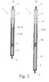
- the proposed drive device 1 is assigned to a hatch 2 of a motor vehicle.
- hatch reference is made to the introductory part of the specification.
- the drive device 1 comprises two drive sections 3, 4 that are linearly movable relative to each other between a retracted position ( Fig. 2a ) and an extended position ( Fig. 2b ).
- the expression "position” here describes the position of the two drive sections 3, 4 relative to each other.
- Each drive section 3, 4 is provided with a connector 5, 6 for the connection to the hatch 2 and the body 7 of the motor vehicle. As shown in Fig. 2 , those connectors 5, 6 are designed as ball sockets that may be engaged with respective ball heads.
- the two drive sections 3, 4 are spring biased against each other into the extended position ( Fig. 2b ) by a spring arrangement 8.
- the drive device 1 shown in Fig. 2 is solely spring driven by the spring arrangement 8 as will be explained later in more detail.
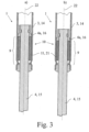
- Fig. 3 shows that the drive device 1 comprises an end stop 9 to limit the drive motion to the extended position.
- the end stop 9 blocks the drive sections 3, 4 from moving beyond the extended position.
- the end stop 9 comprises a special damping arrangement 10 with a deformation zone 11.
- the damping arrangement 10 damps the drive motion mainly based on plastic deformation of the deformation zone 11.
- a drive motion into the end stop 9 corresponds to moving the two drive sections 3, 4 into the extended position shown in Fig. 2b .
- Fig. 3a shows that in this extended position the end stop 9, which is connected to the first drive section 3, is in blocking engagement with a component 4a of the second drive section 4. Accordingly during a drive motion into the end stop 9 an impact occurs between the drive sections 3, 4, here between the component 4a and the end stop 9.
- the damping arrangement 10 damps the drive motion mainly based on plastic deformation of the deformation zone 11.
- the speed-threshold is above the speed range of the drive motion for normal operation.
- damping of the drive motion based on elastic deformation of the deformation zone 11 is proposed.
- elastic deformation generally goes along with loss of kinematic energy, which mainly goes back on internal friction of the deformation zone 11.
- the elastic deformation of the deformation zone 11 leads to an expansion of the impact between the two drive sections 3, 4 in the time domain. This means that the kinematic energy of the drive motion is being converted into potential elastic energy within a relative large time interval which in the end means that the resulting forces acting between the drive sections 3, 4 during the - expanded - impact are comparably low. For such low speeds the subsequent swing back motion is not critical.
- the damping arrangement 10 damps the drive motion into the end stop 9 mainly based on elastic deformation of the deformation zone 11, if the speed of the drive motion is below a predetermined speed-threshold.
- the speed which leads to damping based on elastic deformation, is within the speed range for normal operation.
- the above noted combination of plastic deformation and elastic deformation based on the speed of the drive motion may be realized by a corresponding geometry, structure and material of the deformation zone.
- the drive motion with high speed which is being damped mainly based on plastic deformation may go back on misuse situations as noted above, induced by user operation. Such drive motion may, however, also be generated by the drive device 1 itself.
- An example would be the breakage of a connector 4, 5 and the resulting, impulse like expansion of the spring arrangement 8. Accordingly, the damping arrangement 10 damps at least part of the drive motion into the end stop 9, that is generated by the drive device 1 itself, mainly based on plastic deformation of the deformation zone 11 as noted above.
- the drive device 1 is non-self-locking such that the drive motion may be induced manually by a user acting on the hatch 2, which increases the flexibility for the user on the one hand, but generally opens the door for possible, above noted misuse situations on the other hand.
- the embodiments shown in the drawings display a spring arrangement 8 that comprises a coil compression spring 8a that urges the drive sections 3, 4 into the extracted end position.
- the application of a coil compression spring 8a for the drive device 1 leads to a very compact structure, if the coil compression spring 8a is aligned to the direction of the linear drive motion between the drive sections 3, 4.
- the embodiments for the drive devices 1 shown in fig. 2 to 4 are solely spring driven devices acting in an opening direction or a closing direction of the hatch 2. In particular if the hatch 2 is a liftgate as shown in fig. 1 the spring driven device 1 acts in an opening direction of the hatch 2 in order to support the hatch 2 against the forces of gravity.
- the drive device 1 shown in fig. 5 is partly motor driven and comprises an electric motor 12 and a gear mechanism 13 acting in an opening direction and/or in a closing direction of the hatch 2.
- the drive device 1 is designed as a bidirectional drive device 1 that provides a motorized support of the hatch 2 in the closing direction as well as in the opening direction.
- the spring arrangement 8 supports the electric motor 12 by acting onto the hatch 2 in the opening direction.
- the motor driven device 1 is of slim design which mainly goes back on the gear mechanism 13 being a spindle-spindle nut gear mechanism. As a result the drive device 1 is designed as a spindle drive.
- one drive section 3 comprises a tube 14 and the other drive section 4 comprises a rod 15.
- the rod 15 is in sliding ( Fig. 2 ) and/or screwing ( Fig. 5 ) engagement with the inside of the tube 14.
- the rod 15 comprises a slider 16 for the sliding engagement with the tube 14.
- the slider 16 together with the tube 14 serve as a guide for the rod 15.
- fig. 5 also shows a screwing engagement between the rod 15 and the tube 14.
- the rod 15 is provided with an outer screw thread 17, while the tube 14 is provided with inner screw thread 18, which is part of a spindle nut 19.
- the rod 15, accordingly, is designed as a spindle 20 of the spindle-spindle nut gear mechanism 13.
- the deformation zone 11 shown in fig. 3 is provided by a damping element 21 that is plastically deformable by a driving motion for damping, as shown in fig. 3b .
- the damping element 21 is at least partly made of a foam material, such as a plastic foam material, or a polyurethane (PUR) material.
- PUR polyurethane
- an aluminum foam material may well be applied for the damping element 21.
- the damping element 21 is designed as a separate part. This allows easy manufacturing. It is then also generally possible to replace the damping element 21 if the above noted plastic deformation has taken place.
- the damping element 21 may also be a two or more component element, wherein, for example, one component mainly provides the plastic deformation, while another part mainly provides the elastic deformation.
- the damping element 21 is designed as a bushing that is plastically deformed along its axial extension 22 for damping. As also shown in fig. 3 the above noted rod 15 extends though the bushing 21 with play remaining between the rod 15 and the bushing 21.
- plastic deformation is shown in Fig. 3b .
- the damping of the drive motion by plastic deformation is a very effective measure to absorb the kinematic energy which goes back on the drive motion.
- the plastic deformation may also be used as a proof that a misuse situation has actually taken place, for example, when deciding about warranty claims.
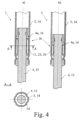
- Fig. 4 shows an alternative for the realization of the deformation zone 11.
- the deformation zone 11 is an axial section of the tube 14 or the rod 15, which axial section is basically deformable by the engagement between the tube 14 and the rod 15 during a drive motion into the end stop 9.
- Fig. 4a shows that the tube 14 provides a deformation zone 11 with a deformation arrangement 23, which deformation arrangement 23 may be basically deformed by an engagement with the rod 15, in further detail with the slider 16 of the rod 15.
- the deformation arrangement 23 disclosed in Fig. 4 is realized as a number of axially extendings ribs 24, as may be taken from sectional view A-A of Fig. 4a .
- the rod 15, in particular the slider 16 may be stuck in the deformation arrangement 23, which again may serve as a proof for a misuse situation. In any case such proof may be seen in the deformation of the ribs 24 as well.
- the embodiments for the deformation zone 11 may well be applied to the drive device shown in Fig. 5 , taking into account that the rod 15 corresponds to the spindle 20.
- the hatch 2 serves for closing an opening 2a in the motor vehicle body 7.
- the drive device 1 is arranged sideways of the opening 2a.
- two proposed drive devices 1 are provided on opposite sides of the opening 2a of the motor vehicle body 7.
- one drive device 1 of the hatch arrangement is solely spring driven.
- another drive device 1 is provided which is at least partly motor driven and which comprises an electric motor 12 and a gear mechanism 13 acting in an opening direction and/or a closing direction of the hatch 2.
- both drive devices 1 are drive devices according to the first teaching.
- only one of the drive devices 1 is designed according to the first teaching.
- only the solely spring driven device 1 comprises an end stop 9 with a damping arrangement 10, which end stop 9 is assigned to the extended position.
- the motorized drive device may be designed independently from the end stop 9, as the end stop 9 is only arranged at the other, solely spring driven device 1.
Landscapes
- Engineering & Computer Science (AREA)
- General Engineering & Computer Science (AREA)
- Power Engineering (AREA)
- Mechanical Engineering (AREA)
- Power-Operated Mechanisms For Wings (AREA)
- Closing And Opening Devices For Wings, And Checks For Wings (AREA)
- Vibration Dampers (AREA)
- Superstructure Of Vehicle (AREA)
Claims (12)
- Antriebsvorrichtung für eine Heckklappe (2) eines Kraftfahrzeugs, wobei die Antriebsvorrichtung (1) zwei Antriebsabschnitte (3, 4) umfasst, die zwischen einer eingefahrenen Position und einer ausgefahrenen Position zueinander linear beweglich sind,wobei die Antriebsabschnitte (3, 4) durch eine Federanordnung (8) in die ausgefahrene Position gegeneinander vorgespannt sind undwobei ein Endanschlag (9) vorgesehen ist, um die Antriebsbewegung zwischen den Antriebsabschnitten (3, 4) in die ausgefahrene Position zu beschränken;dadurch gekennzeichnet,dass der Endanschlag (9) eine Dämpfungsanordnung (10) mit einem Verformungsbereich (11) umfasst,dass während einer Antriebsbewegung in den Endanschlag (9), in Abhängigkeit von der Geschwindigkeit der Antriebsbewegung, die Dämpfungsanordnung (10) die Antriebsbewegung hauptsächlich auf Grundlage der plastischen Verformung des Verformungsbereichs (11) dämpft, dass der Verformungsbereich (11) durch ein Dämpfungselement (21) vorgesehen ist, das durch eine Antriebsbewegung zum Dämpfen plastisch verformbar ist, unddass das Dämpfungselement (21) als Buchse ausgestaltet ist, die entlang ihrer axialen Ausdehnung durch eine Antriebsbewegung zum Dämpfen plastisch verformbar ist.
- Antriebsvorrichtung nach Anspruch 1, wobei die Dämpfungsanordnung (10) die Antriebsbewegung hauptsächlich auf Grundlage der plastischen Verformung des Verformungsbereichs (11) für eine Antriebsbewegung mit einer Geschwindigkeit, die über einem festgelegten Geschwindigkeitsschwellenwert liegt, dämpft, vorzugsweise wobei der festgelegte Geschwindigkeitsschwellenwert über dem Geschwindigkeitsbereich der Antriebsbewegung für den Normalbetrieb liegt.
- Antriebsvorrichtung nach Anspruch 1, wobei die Dämpfungsanordnung (10) die Antriebsbewegung hauptsächlich auf Grundlage der elastischen Verformung des Verformungsbereichs (11) für eine Antriebsbewegung mit einer Geschwindigkeit, die unter einem festgelegten Geschwindigkeitsschwellenwert liegt, dämpft, vorzugsweise wobei der festgelegte Geschwindigkeitsschwellenwert innerhalb des Geschwindigkeitsbereichs für den Normalbetrieb liegt.
- Antriebsvorrichtung nach Anspruch 1, wobei die Dämpfungsanordnung (10) zumindest einen Teil der Antriebsbewegung in den Endanschlag (9), der von der Antriebsvorrichtung (1) selbst erzeugt wird, hauptsächlich auf Grundlage der plastischen Verformung des Verformungsbereichs (11) dämpft.
- Antriebsvorrichtung nach Anspruch 1, wobei die Antriebsvorrichtung (1) nicht selbstsperrend ist, sodass die Antriebsbewegung durch einen auf die Heckklappe (2) wirkenden Anwender manuell herbeigeführt werden kann.
- Antriebsvorrichtung nach Anspruch 1, wobei die Federanordnung (8) eine Schraubendruckfeder (8a) umfasst, welche die Antriebsabschnitte (3, 4) in die ausgefahrene Position drückt.
- Antriebsvorrichtung nach Anspruch 1, wobei die Antriebsvorrichtung (1) lediglich federbetrieben ist oder wobei die Antriebsvorrichtung (1) zumindest teilweise motorbetrieben ist und einen Elektromotor (12) und einen Getriebemechanismus (13) umfasst, vorzugsweise wobei der Getriebemechanismus (13) ein Spindel-Spindelmutter-Getriebemechanismus ist.
- Antriebsvorrichtung nach Anspruch 1, wobei ein Antriebsabschnitt (3) ein Rohr (14) umfasst und der andere Antriebsabschnitt (4) eine Stange (15) umfasst, wobei die Stange (15) mit dem Inneren des Rohrs (14) im Schiebe- und/oder Schraubeingriff ist.
- Antriebsvorrichtung nach Anspruch 8, wobei die Stange (15) die Spindel (20) des Spindel-Spindelmutter-Getriebemechanismus ist und/oder wobei die Stange einen Schieber für den Schiebeeingriff in das Rohr (13) umfasst.
- Antriebsvorrichtung nach Anspruch 1, wobei sich die Stange (15) mit verbleibendem Spiel zwischen der Stange (15) und der Buchse (21) durch die Buchse (21) erstreckt.
- Heckklappenanordnung eines Kraftfahrzeugs mit einer Heckklappe (2) und einer Antriebsvorrichtung (1) zum Antreiben der Heckklappe (2) nach Anspruch 1.
- Heckklappenanordnung nach Anspruch 11, wobei die Antriebsvorrichtung (1) lediglich federbetrieben ist und eine zusätzliche Antriebsvorrichtung vorgesehen ist, die zumindest teilweise motorbetrieben ist und einen Elektromotor und einen Getriebemechanismus umfasst, der in eine Öffnungsrichtung und/oder eine Schließrichtung der Heckklappe (2) wirkt, wobei der Endanschlag (9) der ausgefahrenen Position zugeordnet ist.
Applications Claiming Priority (2)
| Application Number | Priority Date | Filing Date | Title |
|---|---|---|---|
| US14/020,090 US9260899B2 (en) | 2013-09-06 | 2013-09-06 | Drive device for a hatch of a motor vehicle |
| PCT/EP2014/066302 WO2015032554A1 (en) | 2013-09-06 | 2014-07-29 | Drive device for a hatch of a motor vehicle |
Publications (2)
| Publication Number | Publication Date |
|---|---|
| EP3042018A1 EP3042018A1 (de) | 2016-07-13 |
| EP3042018B1 true EP3042018B1 (de) | 2024-09-11 |
Family
ID=51298722
Family Applications (1)
| Application Number | Title | Priority Date | Filing Date |
|---|---|---|---|
| EP14748152.7A Active EP3042018B1 (de) | 2013-09-06 | 2014-07-29 | Antriebsvorrichtung für die luke eines kraftfahrzeugs |
Country Status (7)
| Country | Link |
|---|---|
| US (1) | US9260899B2 (de) |
| EP (1) | EP3042018B1 (de) |
| JP (1) | JP6320536B2 (de) |
| KR (1) | KR101848190B1 (de) |
| CN (1) | CN105658895B (de) |
| DE (1) | DE202014011506U1 (de) |
| WO (1) | WO2015032554A1 (de) |
Families Citing this family (20)
| Publication number | Priority date | Publication date | Assignee | Title |
|---|---|---|---|---|
| DE102011122316A1 (de) * | 2011-12-23 | 2013-06-27 | Brose Fahrzeugteile Gmbh & Co. Kommanditgesellschaft, Hallstadt | Spindelantrieb für ein Verstellelement eines Kraftfahrzeugs |
| JP6011611B2 (ja) * | 2012-03-14 | 2016-10-19 | アイシン精機株式会社 | 開閉体の開閉補助装置 |
| DE102012018826A1 (de) | 2012-09-25 | 2014-03-27 | Brose Fahrzeugteile Gmbh & Co. Kommanditgesellschaft, Hallstadt | Spindelantrieb für ein Verstellelement eines Kraftfahrzeugs |
| CN107250579B (zh) * | 2015-02-23 | 2019-04-19 | 三菱电机株式会社 | 轴支承部的耐热结构及致动器 |
| US10100568B2 (en) * | 2015-08-12 | 2018-10-16 | Magna Closures Inc. | Electromechanical strut with lateral support feature |
| DE102016103800A1 (de) * | 2016-03-03 | 2017-09-07 | Brose Fahrzeugteile Gmbh & Co. Kg, Bamberg | Antriebsanordnung einer Klappenanordnung eines Kraftfahrzeugs |
| DE102017102173A1 (de) * | 2017-02-03 | 2018-08-09 | Brose Fahrzeugteile Gmbh & Co. Kommanditgesellschaft, Bamberg | Spindelantrieb |
| DE102017127859A1 (de) * | 2017-11-24 | 2019-05-29 | Brose Fahrzeugteile Gmbh & Co. Kommanditgesellschaft, Bamberg | Antriebsvorrichtung für ein Verschlusselement eines Kraftfahrzeugs |
| DE102017128392A1 (de) * | 2017-11-30 | 2019-06-06 | U-Shin Deutschland Zugangssysteme Gmbh | Spindelantriebsbaugruppe, Fahrzeugklappe mit einer Spindelantriebsbaugruppe sowie Verfahren zur Montage einer Spindelantriebsbaugruppe |
| DE102017128387A1 (de) * | 2017-11-30 | 2019-06-06 | U-Shin Deutschland Zugangssysteme Gmbh | Spindelantriebsbaugruppe sowie Fahrzeugklappe mit einer Spindelantriebsbaugruppe |
| DE102017128389A1 (de) * | 2017-11-30 | 2019-06-06 | U-Shin Deutschland Zugangssysteme Gmbh | Spindelantriebsbaugruppe sowie Fahrzeugklappe mit einer Spindelantriebsbaugruppe |
| DE102018121033A1 (de) * | 2018-08-29 | 2020-03-05 | Brose Fahrzeugteile Gmbh & Co. Kommanditgesellschaft, Bamberg | Spindelantrieb für ein Verschlusselement eines Kraftfahrzeugs |
| DE102019209085A1 (de) * | 2019-06-24 | 2020-12-24 | Geze Gmbh | Antrieb für einen Flügel einer Tür oder eines Fensters |
| US11414911B2 (en) * | 2020-01-24 | 2022-08-16 | Overhead Door Corporation | Swing door operator with offset spring |
| CN112065207A (zh) * | 2020-09-17 | 2020-12-11 | 广东骏驰科技股份有限公司 | 一种新型电动电撑杆 |
| KR20230031490A (ko) | 2021-08-27 | 2023-03-07 | (주)대한솔루션 | 자동차용 트렁크 자동 개폐 장치 |
| DE102022104079A1 (de) | 2022-02-22 | 2023-08-24 | U-Shin Deutschland Zugangssysteme Gmbh | Spindelbaugruppe für eine Spindelantriebsvorrichtung |
| DE102022108114A1 (de) * | 2022-04-05 | 2023-10-05 | Brose Fahrzeugteile Se & Co. Kommanditgesellschaft, Bamberg | Antriebsvorrichtung für ein Verschlusselement eines Kraftfahrzeugs |
| CN115450516B (zh) * | 2022-09-23 | 2025-03-11 | 浙江极氪智能科技有限公司 | 驱动装置、车辆及驱动装置的控制方法 |
| US12274649B1 (en) * | 2023-11-21 | 2025-04-15 | Timothy Thomas | Motorized coffin lid device |
Citations (9)
| Publication number | Priority date | Publication date | Assignee | Title |
|---|---|---|---|---|
| EP0113616A1 (de) | 1982-12-08 | 1984-07-18 | AEROSPATIALE Société Nationale Industrielle | Kufenlandegestell mit Einrichtung zur Umwandlung von Energie durch plastische Verformung und/oder Mitteln zur Kraftbegrenzung |
| US20040178552A1 (en) * | 2003-03-10 | 2004-09-16 | Schudt Joseph A. | Upper strut assembly |
| DE102005048942A1 (de) | 2005-10-13 | 2007-04-19 | Stabilus Gmbh | Kolben-Zylinder-Einheit |
| US20070138722A1 (en) | 2005-11-02 | 2007-06-21 | Hanna Ronald J | Power strut assembly |
| WO2007113272A1 (en) * | 2006-03-31 | 2007-10-11 | Valeo Sicherheitssysteme Gmbh | Adjusting device having a spindle drive |
| WO2008026423A1 (en) * | 2006-08-31 | 2008-03-06 | Takata Corporation | Actuator, hood lifter, hood lifting system, and method of absorbing impact on actuator |
| EP2037067A1 (de) * | 2007-09-11 | 2009-03-18 | Valeo Sicherheitssysteme GmbH | Antriebseinrichtung für eine Kraftfahrzeugtür |
| DE102008008294A1 (de) | 2008-02-07 | 2009-08-13 | Stabilus Gmbh | Antriebseinrichtung |
| DE102008039304A1 (de) | 2008-08-22 | 2010-02-25 | Audi Ag | Lenkungsaktuator für eine hintere Radaufhängung |
Family Cites Families (13)
| Publication number | Priority date | Publication date | Assignee | Title |
|---|---|---|---|---|
| DE4028448A1 (de) * | 1990-09-07 | 1992-03-12 | Suspa Compart Ag | Reversibler pralldaempfer, insbesondere fuer kraftfahrzeuge |
| JPH07317827A (ja) * | 1994-05-24 | 1995-12-08 | Showa:Kk | ガススプリングのリバウンドストッパ機構 |
| DE102004007550A1 (de) * | 2004-02-17 | 2005-09-01 | Daimlerchrysler Ag | Anschlagsvorrichtung für einen Spindelantrieb |
| DE202005016953U1 (de) * | 2005-10-27 | 2007-03-08 | BROSE SCHLIEßSYSTEME GMBH & CO. KG | Antriebsanordnung zur motorischen Betätigung eines Funktionselements in einem Kraftfahrzeug |
| US8006817B2 (en) * | 2005-11-02 | 2011-08-30 | Dura Global Technologies, Llc | Power strut assembly |
| JP2007331699A (ja) * | 2006-06-19 | 2007-12-27 | Brose Schliesssysteme Gmbh & Co Kg | 自動車の開口の閉鎖部品作動装置 |
| DE102006042023A1 (de) * | 2006-09-07 | 2008-03-27 | Stabilus Gmbh | Antriebseinrichtung |
| DE102008057014B4 (de) | 2008-11-12 | 2014-07-24 | BROSE SCHLIEßSYSTEME GMBH & CO. KG | Antriebsanordnung zur motorischen Verstellung eines Verschlusselements in einem Kraftfahrzeug |
| CN102317451A (zh) * | 2008-12-23 | 2012-01-11 | 丹尼斯科公司 | 具有木聚糖酶活性的多肽 |
| DE202009002622U1 (de) | 2009-02-25 | 2010-07-22 | Brose Fahrzeugteile Gmbh & Co. Kommanditgesellschaft, Hallstadt | Antriebsanordnung zur Betätigung einer Klappe eines Kraftfahrzeugs |
| KR101020488B1 (ko) * | 2009-06-12 | 2011-03-09 | 주식회사 광진엔지니어링 | 후방도어 개폐수단 |
| DE102009058503B4 (de) * | 2009-12-16 | 2021-02-25 | Dr. Ing. H.C. F. Porsche Aktiengesellschaft | Einstellbare Heckklappenabstützung |
| CN201818174U (zh) * | 2010-09-15 | 2011-05-04 | 宁波信泰机械有限公司 | 汽车电动尾门驱动机构 |
-
2013
- 2013-09-06 US US14/020,090 patent/US9260899B2/en active Active
-
2014
- 2014-07-29 EP EP14748152.7A patent/EP3042018B1/de active Active
- 2014-07-29 JP JP2016539447A patent/JP6320536B2/ja active Active
- 2014-07-29 KR KR1020167009123A patent/KR101848190B1/ko active Active
- 2014-07-29 CN CN201480049027.8A patent/CN105658895B/zh active Active
- 2014-07-29 DE DE202014011506.0U patent/DE202014011506U1/de not_active Expired - Lifetime
- 2014-07-29 WO PCT/EP2014/066302 patent/WO2015032554A1/en not_active Ceased
Patent Citations (11)
| Publication number | Priority date | Publication date | Assignee | Title |
|---|---|---|---|---|
| EP0113616A1 (de) | 1982-12-08 | 1984-07-18 | AEROSPATIALE Société Nationale Industrielle | Kufenlandegestell mit Einrichtung zur Umwandlung von Energie durch plastische Verformung und/oder Mitteln zur Kraftbegrenzung |
| US20040178552A1 (en) * | 2003-03-10 | 2004-09-16 | Schudt Joseph A. | Upper strut assembly |
| DE102005048942A1 (de) | 2005-10-13 | 2007-04-19 | Stabilus Gmbh | Kolben-Zylinder-Einheit |
| DE102005048942B4 (de) * | 2005-10-13 | 2007-06-28 | Stabilus Gmbh | Kolben-Zylinder-Einheit |
| US20070138722A1 (en) | 2005-11-02 | 2007-06-21 | Hanna Ronald J | Power strut assembly |
| WO2007113272A1 (en) * | 2006-03-31 | 2007-10-11 | Valeo Sicherheitssysteme Gmbh | Adjusting device having a spindle drive |
| WO2008026423A1 (en) * | 2006-08-31 | 2008-03-06 | Takata Corporation | Actuator, hood lifter, hood lifting system, and method of absorbing impact on actuator |
| EP2037067A1 (de) * | 2007-09-11 | 2009-03-18 | Valeo Sicherheitssysteme GmbH | Antriebseinrichtung für eine Kraftfahrzeugtür |
| EP2037067B1 (de) | 2007-09-11 | 2014-11-26 | U-Shin Deutschland Zugangssysteme GmbH | Antriebseinrichtung für eine Kraftfahrzeugtür |
| DE102008008294A1 (de) | 2008-02-07 | 2009-08-13 | Stabilus Gmbh | Antriebseinrichtung |
| DE102008039304A1 (de) | 2008-08-22 | 2010-02-25 | Audi Ag | Lenkungsaktuator für eine hintere Radaufhängung |
Also Published As
| Publication number | Publication date |
|---|---|
| CN105658895B (zh) | 2017-11-28 |
| US9260899B2 (en) | 2016-02-16 |
| KR101848190B1 (ko) | 2018-04-11 |
| KR20160051896A (ko) | 2016-05-11 |
| CN105658895A (zh) | 2016-06-08 |
| EP3042018A1 (de) | 2016-07-13 |
| US20150069869A1 (en) | 2015-03-12 |
| WO2015032554A1 (en) | 2015-03-12 |
| JP6320536B2 (ja) | 2018-05-09 |
| DE202014011506U1 (de) | 2021-07-13 |
| JP2016532036A (ja) | 2016-10-13 |
Similar Documents
| Publication | Publication Date | Title |
|---|---|---|
| EP3042018B1 (de) | Antriebsvorrichtung für die luke eines kraftfahrzeugs | |
| US7657970B2 (en) | Device for preventing door slamming | |
| JP7254801B2 (ja) | 自動車の閉鎖エレメントのための駆動装置 | |
| CN106489041B (zh) | 用于机动车的关闭元件的弹簧驱动器 | |
| CN100464051C (zh) | 螺旋动作减震器 | |
| CN104554126B (zh) | 用于车辆的主动式发动机罩装置 | |
| CN102416983A (zh) | 用于车辆的主动发动机罩锁扣系统 | |
| CN100387453C (zh) | 车窗调整器线缆张紧装置、车窗调整器及无框车门 | |
| CN108463141A (zh) | 抽屉抽拉导向装置 | |
| US20200263469A1 (en) | Linear Damper | |
| CN106744207B (zh) | 电梯防护门 | |
| CN116084785B (zh) | 一种车门限位器、车门及车辆 | |
| WO2009050413A1 (en) | Improvements in movement controls | |
| KR101916534B1 (ko) | 도어 체커 기능이 구비된 차량용 도어 힌지 | |
| US20160208517A1 (en) | Vehicle tailgate locking element guard | |
| KR100448064B1 (ko) | 자동차용 도어체커장치 | |
| KR102710041B1 (ko) | 창문 부착형 충격 완화 댐퍼 | |
| KR20120085425A (ko) | 슬라이드 레일 감속 댐퍼 완충 시스템 | |
| CN217176354U (zh) | 一种地铁人防用的防护门 | |
| CN211647753U (zh) | 缓震装置及自动门 | |
| CN111501685B (zh) | 一种离合卷筒式固定卷扬启闭机缓冲限位装置 | |
| JP2008038417A (ja) | 開口部閉鎖部材の制動装置及びそれを有する開口部閉鎖部材 | |
| DE102006024643A1 (de) | Schutzvorrichtung für eine Kraftfahrzeugtür, Kraftfahrzeugtür mit Schutzvorrichtung und Kraftfahrzeug mit Schutzvorrichtung | |
| CN105888421A (zh) | 一种门扇转轴和包括该门扇转轴的汽车 | |
| CN105350873B (zh) | 一种车库门 |
Legal Events
| Date | Code | Title | Description |
|---|---|---|---|
| PUAI | Public reference made under article 153(3) epc to a published international application that has entered the european phase |
Free format text: ORIGINAL CODE: 0009012 |
|
| 17P | Request for examination filed |
Effective date: 20160406 |
|
| AK | Designated contracting states |
Kind code of ref document: A1 Designated state(s): AL AT BE BG CH CY CZ DE DK EE ES FI FR GB GR HR HU IE IS IT LI LT LU LV MC MK MT NL NO PL PT RO RS SE SI SK SM TR |
|
| AX | Request for extension of the european patent |
Extension state: BA ME |
|
| RAP1 | Party data changed (applicant data changed or rights of an application transferred) |
Owner name: BROSE FAHRZEUGTEILE GMBH & CO. KOMMANDITGESELLSCHA |
|
| DAX | Request for extension of the european patent (deleted) | ||
| STAA | Information on the status of an ep patent application or granted ep patent |
Free format text: STATUS: EXAMINATION IS IN PROGRESS |
|
| 17Q | First examination report despatched |
Effective date: 20190607 |
|
| TPAC | Observations filed by third parties |
Free format text: ORIGINAL CODE: EPIDOSNTIPA |
|
| RAP3 | Party data changed (applicant data changed or rights of an application transferred) |
Owner name: BROSE FAHRZEUGTEILE SE & CO. KOMMANDITGESELLSCHAFT, BAMBERG |
|
| GRAP | Despatch of communication of intention to grant a patent |
Free format text: ORIGINAL CODE: EPIDOSNIGR1 |
|
| STAA | Information on the status of an ep patent application or granted ep patent |
Free format text: STATUS: GRANT OF PATENT IS INTENDED |
|
| INTG | Intention to grant announced |
Effective date: 20240404 |
|
| GRAS | Grant fee paid |
Free format text: ORIGINAL CODE: EPIDOSNIGR3 |
|
| P01 | Opt-out of the competence of the unified patent court (upc) registered |
Free format text: CASE NUMBER: APP_37879/2024 Effective date: 20240701 |
|
| GRAA | (expected) grant |
Free format text: ORIGINAL CODE: 0009210 |
|
| STAA | Information on the status of an ep patent application or granted ep patent |
Free format text: STATUS: THE PATENT HAS BEEN GRANTED |
|
| AK | Designated contracting states |
Kind code of ref document: B1 Designated state(s): AL AT BE BG CH CY CZ DE DK EE ES FI FR GB GR HR HU IE IS IT LI LT LU LV MC MK MT NL NO PL PT RO RS SE SI SK SM TR |
|
| REG | Reference to a national code |
Ref country code: GB Ref legal event code: FG4D |
|
| REG | Reference to a national code |
Ref country code: CH Ref legal event code: EP |
|
| REG | Reference to a national code |
Ref country code: DE Ref legal event code: R096 Ref document number: 602014090853 Country of ref document: DE |
|
| REG | Reference to a national code |
Ref country code: IE Ref legal event code: FG4D |
|
| REG | Reference to a national code |
Ref country code: LT Ref legal event code: MG9D |
|
| PG25 | Lapsed in a contracting state [announced via postgrant information from national office to epo] |
Ref country code: NO Free format text: LAPSE BECAUSE OF FAILURE TO SUBMIT A TRANSLATION OF THE DESCRIPTION OR TO PAY THE FEE WITHIN THE PRESCRIBED TIME-LIMIT Effective date: 20241211 |
|
| REG | Reference to a national code |
Ref country code: NL Ref legal event code: MP Effective date: 20240911 |
|
| PG25 | Lapsed in a contracting state [announced via postgrant information from national office to epo] |
Ref country code: GR Free format text: LAPSE BECAUSE OF FAILURE TO SUBMIT A TRANSLATION OF THE DESCRIPTION OR TO PAY THE FEE WITHIN THE PRESCRIBED TIME-LIMIT Effective date: 20241212 Ref country code: FI Free format text: LAPSE BECAUSE OF FAILURE TO SUBMIT A TRANSLATION OF THE DESCRIPTION OR TO PAY THE FEE WITHIN THE PRESCRIBED TIME-LIMIT Effective date: 20240911 |
|
| PG25 | Lapsed in a contracting state [announced via postgrant information from national office to epo] |
Ref country code: BG Free format text: LAPSE BECAUSE OF FAILURE TO SUBMIT A TRANSLATION OF THE DESCRIPTION OR TO PAY THE FEE WITHIN THE PRESCRIBED TIME-LIMIT Effective date: 20240911 |
|
| PG25 | Lapsed in a contracting state [announced via postgrant information from national office to epo] |
Ref country code: LV Free format text: LAPSE BECAUSE OF FAILURE TO SUBMIT A TRANSLATION OF THE DESCRIPTION OR TO PAY THE FEE WITHIN THE PRESCRIBED TIME-LIMIT Effective date: 20240911 |
|
| PG25 | Lapsed in a contracting state [announced via postgrant information from national office to epo] |
Ref country code: HR Free format text: LAPSE BECAUSE OF FAILURE TO SUBMIT A TRANSLATION OF THE DESCRIPTION OR TO PAY THE FEE WITHIN THE PRESCRIBED TIME-LIMIT Effective date: 20240911 |
|
| PG25 | Lapsed in a contracting state [announced via postgrant information from national office to epo] |
Ref country code: RS Free format text: LAPSE BECAUSE OF FAILURE TO SUBMIT A TRANSLATION OF THE DESCRIPTION OR TO PAY THE FEE WITHIN THE PRESCRIBED TIME-LIMIT Effective date: 20241211 Ref country code: ES Free format text: LAPSE BECAUSE OF FAILURE TO SUBMIT A TRANSLATION OF THE DESCRIPTION OR TO PAY THE FEE WITHIN THE PRESCRIBED TIME-LIMIT Effective date: 20240911 |
|
| REG | Reference to a national code |
Ref country code: SK Ref legal event code: T3 Ref document number: E 45487 Country of ref document: SK |
|
| PG25 | Lapsed in a contracting state [announced via postgrant information from national office to epo] |
Ref country code: RS Free format text: LAPSE BECAUSE OF FAILURE TO SUBMIT A TRANSLATION OF THE DESCRIPTION OR TO PAY THE FEE WITHIN THE PRESCRIBED TIME-LIMIT Effective date: 20241211 Ref country code: NO Free format text: LAPSE BECAUSE OF FAILURE TO SUBMIT A TRANSLATION OF THE DESCRIPTION OR TO PAY THE FEE WITHIN THE PRESCRIBED TIME-LIMIT Effective date: 20241211 Ref country code: LV Free format text: LAPSE BECAUSE OF FAILURE TO SUBMIT A TRANSLATION OF THE DESCRIPTION OR TO PAY THE FEE WITHIN THE PRESCRIBED TIME-LIMIT Effective date: 20240911 Ref country code: HR Free format text: LAPSE BECAUSE OF FAILURE TO SUBMIT A TRANSLATION OF THE DESCRIPTION OR TO PAY THE FEE WITHIN THE PRESCRIBED TIME-LIMIT Effective date: 20240911 Ref country code: GR Free format text: LAPSE BECAUSE OF FAILURE TO SUBMIT A TRANSLATION OF THE DESCRIPTION OR TO PAY THE FEE WITHIN THE PRESCRIBED TIME-LIMIT Effective date: 20241212 Ref country code: FI Free format text: LAPSE BECAUSE OF FAILURE TO SUBMIT A TRANSLATION OF THE DESCRIPTION OR TO PAY THE FEE WITHIN THE PRESCRIBED TIME-LIMIT Effective date: 20240911 Ref country code: ES Free format text: LAPSE BECAUSE OF FAILURE TO SUBMIT A TRANSLATION OF THE DESCRIPTION OR TO PAY THE FEE WITHIN THE PRESCRIBED TIME-LIMIT Effective date: 20240911 Ref country code: BG Free format text: LAPSE BECAUSE OF FAILURE TO SUBMIT A TRANSLATION OF THE DESCRIPTION OR TO PAY THE FEE WITHIN THE PRESCRIBED TIME-LIMIT Effective date: 20240911 |
|
| REG | Reference to a national code |
Ref country code: AT Ref legal event code: MK05 Ref document number: 1722813 Country of ref document: AT Kind code of ref document: T Effective date: 20240911 |
|
| PG25 | Lapsed in a contracting state [announced via postgrant information from national office to epo] |
Ref country code: NL Free format text: LAPSE BECAUSE OF FAILURE TO SUBMIT A TRANSLATION OF THE DESCRIPTION OR TO PAY THE FEE WITHIN THE PRESCRIBED TIME-LIMIT Effective date: 20240911 |
|
| PG25 | Lapsed in a contracting state [announced via postgrant information from national office to epo] |
Ref country code: IS Free format text: LAPSE BECAUSE OF FAILURE TO SUBMIT A TRANSLATION OF THE DESCRIPTION OR TO PAY THE FEE WITHIN THE PRESCRIBED TIME-LIMIT Effective date: 20250111 Ref country code: PT Free format text: LAPSE BECAUSE OF FAILURE TO SUBMIT A TRANSLATION OF THE DESCRIPTION OR TO PAY THE FEE WITHIN THE PRESCRIBED TIME-LIMIT Effective date: 20250113 |
|
| PG25 | Lapsed in a contracting state [announced via postgrant information from national office to epo] |
Ref country code: RO Free format text: LAPSE BECAUSE OF FAILURE TO SUBMIT A TRANSLATION OF THE DESCRIPTION OR TO PAY THE FEE WITHIN THE PRESCRIBED TIME-LIMIT Effective date: 20240911 Ref country code: SM Free format text: LAPSE BECAUSE OF FAILURE TO SUBMIT A TRANSLATION OF THE DESCRIPTION OR TO PAY THE FEE WITHIN THE PRESCRIBED TIME-LIMIT Effective date: 20240911 |
|
| PG25 | Lapsed in a contracting state [announced via postgrant information from national office to epo] |
Ref country code: EE Free format text: LAPSE BECAUSE OF FAILURE TO SUBMIT A TRANSLATION OF THE DESCRIPTION OR TO PAY THE FEE WITHIN THE PRESCRIBED TIME-LIMIT Effective date: 20240911 Ref country code: AT Free format text: LAPSE BECAUSE OF FAILURE TO SUBMIT A TRANSLATION OF THE DESCRIPTION OR TO PAY THE FEE WITHIN THE PRESCRIBED TIME-LIMIT Effective date: 20240911 |
|
| PG25 | Lapsed in a contracting state [announced via postgrant information from national office to epo] |
Ref country code: CZ Free format text: LAPSE BECAUSE OF FAILURE TO SUBMIT A TRANSLATION OF THE DESCRIPTION OR TO PAY THE FEE WITHIN THE PRESCRIBED TIME-LIMIT Effective date: 20240911 Ref country code: PL Free format text: LAPSE BECAUSE OF FAILURE TO SUBMIT A TRANSLATION OF THE DESCRIPTION OR TO PAY THE FEE WITHIN THE PRESCRIBED TIME-LIMIT Effective date: 20240911 |
|
| PG25 | Lapsed in a contracting state [announced via postgrant information from national office to epo] |
Ref country code: IT Free format text: LAPSE BECAUSE OF FAILURE TO SUBMIT A TRANSLATION OF THE DESCRIPTION OR TO PAY THE FEE WITHIN THE PRESCRIBED TIME-LIMIT Effective date: 20240911 |
|
| REG | Reference to a national code |
Ref country code: DE Ref legal event code: R026 Ref document number: 602014090853 Country of ref document: DE |
|
| PLBI | Opposition filed |
Free format text: ORIGINAL CODE: 0009260 |
|
| 26 | Opposition filed |
Opponent name: MINEBEAMITSUMI TECHNOLOGY CENTER EUROPE GMBH Effective date: 20250507 |
|
| PLAX | Notice of opposition and request to file observation + time limit sent |
Free format text: ORIGINAL CODE: EPIDOSNOBS2 |
|
| PG25 | Lapsed in a contracting state [announced via postgrant information from national office to epo] |
Ref country code: DK Free format text: LAPSE BECAUSE OF FAILURE TO SUBMIT A TRANSLATION OF THE DESCRIPTION OR TO PAY THE FEE WITHIN THE PRESCRIBED TIME-LIMIT Effective date: 20240911 |
|
| PGFP | Annual fee paid to national office [announced via postgrant information from national office to epo] |
Ref country code: GB Payment date: 20250605 Year of fee payment: 12 |
|
| PGFP | Annual fee paid to national office [announced via postgrant information from national office to epo] |
Ref country code: FR Payment date: 20250610 Year of fee payment: 12 |
|
| PGFP | Annual fee paid to national office [announced via postgrant information from national office to epo] |
Ref country code: SK Payment date: 20250612 Year of fee payment: 12 |
|
| PG25 | Lapsed in a contracting state [announced via postgrant information from national office to epo] |
Ref country code: SE Free format text: LAPSE BECAUSE OF FAILURE TO SUBMIT A TRANSLATION OF THE DESCRIPTION OR TO PAY THE FEE WITHIN THE PRESCRIBED TIME-LIMIT Effective date: 20240911 |
|
| PGFP | Annual fee paid to national office [announced via postgrant information from national office to epo] |
Ref country code: DE Payment date: 20250731 Year of fee payment: 12 |
|
| PLBB | Reply of patent proprietor to notice(s) of opposition received |
Free format text: ORIGINAL CODE: EPIDOSNOBS3 |