EP3041997B1 - Verfahren für bedarfsmanagement und steuerung von flüssigkeitsrohrleitungsnetzen - Google Patents
Verfahren für bedarfsmanagement und steuerung von flüssigkeitsrohrleitungsnetzen Download PDFInfo
- Publication number
- EP3041997B1 EP3041997B1 EP14841712.4A EP14841712A EP3041997B1 EP 3041997 B1 EP3041997 B1 EP 3041997B1 EP 14841712 A EP14841712 A EP 14841712A EP 3041997 B1 EP3041997 B1 EP 3041997B1
- Authority
- EP
- European Patent Office
- Prior art keywords
- valves
- fluid
- valve
- network
- pressure head
- Prior art date
- Legal status (The legal status is an assumption and is not a legal conclusion. Google has not performed a legal analysis and makes no representation as to the accuracy of the status listed.)
- Active
Links
Images




Classifications
-
- E—FIXED CONSTRUCTIONS
- E02—HYDRAULIC ENGINEERING; FOUNDATIONS; SOIL SHIFTING
- E02B—HYDRAULIC ENGINEERING
- E02B1/00—Equipment or apparatus for, or methods of, general hydraulic engineering, e.g. protection of constructions against ice-strains
-
- G—PHYSICS
- G05—CONTROLLING; REGULATING
- G05D—SYSTEMS FOR CONTROLLING OR REGULATING NON-ELECTRIC VARIABLES
- G05D7/00—Control of flow
- G05D7/06—Control of flow characterised by the use of electric means
- G05D7/0617—Control of flow characterised by the use of electric means specially adapted for fluid materials
- G05D7/0629—Control of flow characterised by the use of electric means specially adapted for fluid materials characterised by the type of regulator means
- G05D7/0635—Control of flow characterised by the use of electric means specially adapted for fluid materials characterised by the type of regulator means by action on throttling means
- G05D7/0641—Control of flow characterised by the use of electric means specially adapted for fluid materials characterised by the type of regulator means by action on throttling means using a plurality of throttling means
- G05D7/0664—Control of flow characterised by the use of electric means specially adapted for fluid materials characterised by the type of regulator means by action on throttling means using a plurality of throttling means the plurality of throttling means being arranged for the control of a plurality of diverging flows from a single flow
-
- F—MECHANICAL ENGINEERING; LIGHTING; HEATING; WEAPONS; BLASTING
- F17—STORING OR DISTRIBUTING GASES OR LIQUIDS
- F17D—PIPE-LINE SYSTEMS; PIPE-LINES
- F17D1/00—Pipe-line systems
-
- G—PHYSICS
- G05—CONTROLLING; REGULATING
- G05B—CONTROL OR REGULATING SYSTEMS IN GENERAL; FUNCTIONAL ELEMENTS OF SUCH SYSTEMS; MONITORING OR TESTING ARRANGEMENTS FOR SUCH SYSTEMS OR ELEMENTS
- G05B17/00—Systems involving the use of models or simulators of said systems
- G05B17/02—Systems involving the use of models or simulators of said systems electric
-
- G—PHYSICS
- G05—CONTROLLING; REGULATING
- G05B—CONTROL OR REGULATING SYSTEMS IN GENERAL; FUNCTIONAL ELEMENTS OF SUCH SYSTEMS; MONITORING OR TESTING ARRANGEMENTS FOR SUCH SYSTEMS OR ELEMENTS
- G05B19/00—Program-control systems
-
- G—PHYSICS
- G05—CONTROLLING; REGULATING
- G05D—SYSTEMS FOR CONTROLLING OR REGULATING NON-ELECTRIC VARIABLES
- G05D7/00—Control of flow
- G05D7/06—Control of flow characterised by the use of electric means
-
- G—PHYSICS
- G05—CONTROLLING; REGULATING
- G05D—SYSTEMS FOR CONTROLLING OR REGULATING NON-ELECTRIC VARIABLES
- G05D7/00—Control of flow
- G05D7/06—Control of flow characterised by the use of electric means
- G05D7/0617—Control of flow characterised by the use of electric means specially adapted for fluid materials
- G05D7/0629—Control of flow characterised by the use of electric means specially adapted for fluid materials characterised by the type of regulator means
- G05D7/0635—Control of flow characterised by the use of electric means specially adapted for fluid materials characterised by the type of regulator means by action on throttling means
- G05D7/0641—Control of flow characterised by the use of electric means specially adapted for fluid materials characterised by the type of regulator means by action on throttling means using a plurality of throttling means
-
- G—PHYSICS
- G06—COMPUTING OR CALCULATING; COUNTING
- G06F—ELECTRIC DIGITAL DATA PROCESSING
- G06F17/00—Digital computing or data processing equipment or methods, specially adapted for specific functions
-
- G—PHYSICS
- G16—INFORMATION AND COMMUNICATION TECHNOLOGY [ICT] SPECIALLY ADAPTED FOR SPECIFIC APPLICATION FIELDS
- G16Z—INFORMATION AND COMMUNICATION TECHNOLOGY [ICT] SPECIALLY ADAPTED FOR SPECIFIC APPLICATION FIELDS, NOT OTHERWISE PROVIDED FOR
- G16Z99/00—Subject matter not provided for in other main groups of this subclass
-
- E—FIXED CONSTRUCTIONS
- E02—HYDRAULIC ENGINEERING; FOUNDATIONS; SOIL SHIFTING
- E02B—HYDRAULIC ENGINEERING
- E02B13/00—Irrigation ditches, i.e. gravity flow, open channel water distribution systems
Definitions
- the present invention relates to a method of demand management and control for limited pressure head or gravity fed fluid closed conduit networks, and relates particularly, though not exclusively, to a method of demand management and control for limited pressure head or gravity fed water irrigation pipe networks.
- the method is applicable to both a closed conduits (pipeline network) and open conduits (channel networks).
- Gravity pipe networks typically operate within limited pressure head and therefore are constrained in their capability to meet demand.
- Known models for pipe networks would be used in the management of demand for these networks.
- Data from the SCADA system would be used to calibrate and continually fine-tune the model of the pipe conveyance network based on system identification techniques.
- Flow measurement and pressure head measurements would be located at points on the pipe network that would be deemed necessary to calibrate the model to the desired accuracy.
- the supply points to users are the primary form of control used with a pipe network.
- the controller for a pipe network is much simpler than it is for a channel network with the principle form of control being maintaining the flow at the supply point equal to that of the order.
- Control and management of demand is especially applicable to gravity pipe networks commonly used for the supply of irrigation water. Difficulties have arisen to implement such systems as gravity pipe networks typically operate within limited pressure head and therefore are constrained in their capability to continually meet demand. Gravity pipelines also typically operate at lower pressure heads where there will be greater interaction between flows at outlets due to valve operations. Accordingly, assuming all the parameters such as pipe diameter, flow rate, valve size, etc. being the same, the higher the static pressure head (e.g. from pumping), the less sensitive the impact of flow fluctuations due to valve operations (e.g. valves opening or closing) on other valves in operation.
- Fig. 1 illustrates why operating valves are less sensitive to flow variations in the supply pipeline (e.g. from other opening and closing valves) with a higher pressure head in the pipeline.
- Fig. 1 shows a graph of the hydraulic grade line or pressure head against the valve position for a high pressure at line 10 and for a low pressure or gravity fed hydraulic grade line or pressure head at line 12.
- Gravity fed pipe 14 is shown on a grade with two valves 16 and 18. Although pipe 14 is shown on a grade, it could be horizontal if the water supply is elevated to provide the required pressure head. For line 10, pipe 14 would be coupled to a pump (not shown) to produce a high-pressure head.
- valves can be manually positioned to a set opening to achieve a certain flow, and the flow will not be impacted significantly by the operation of the other valves (e.g. valves opening or closing) in the pipeline.
- low-pressure pipelines require an integrated control and demand management system to manage the valve interaction within the tight hydraulic grade line conditions.
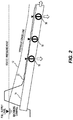
- Fig. 2 shows pipeline 14 separated from Fig. 1 and illustrates the maximum supply pressure 22 which must maintain the pipeline full to ensure the accuracy of the flow meters (not shown) associated with valves 16, 18, and 20. It is important to keep the pipeline full to make the control problem simple and tractable as a "pipe not full” scenario will significantly change the physics that governs the dynamics of pipe flow. Pipe flow transitioning between "pipe full” and “pipe not full” states will make achieving robust control intractable. Maintaining the hydraulic grade line 12 associated with the pipeline 14 above the maximum supply pressure 22 will also ensure that the pressure head at the valves 16, 18 and 20 are high enough to guarantee the flow rate the valves were designed for.
- the low-pressure head or hydraulic grade line 12 associated with pipeline 14 will potentially result in increased controller interaction between the discrete control actions necessary to maintain desired flows at the valves. This is further compounded with gravity pipelines where the flow capacity at the valves is high in relation to the overall flow capacity of the main trunk pipeline. The action of opening or closing valves will impact the pressure head, and therefore flow, at all other valves on the pipeline 14 that are operating. Therefore there will be interaction between various automated valves operating off the pipeline. In this low energy pipeline, the control will be subject to instability. Each movement in a valve has a level of interaction with all the other operating valves plus supply level variation at the source or at the outlet (on-farm). Because of the low pressure in the pipeline 14, the hydraulic grade line 12 is very sensitive to the operation of the valve/outlets.
- FIG. 3 This sensitivity is illustrated in Fig. 3 where a graph of flow and time is shown.
- Line 24 illustrates valve 16 being already open and the effect that the opening of valve 18 has on the network.
- Line 26 illustrates the flow of valve 18.
- Both valves 16 and 18 are trying to maintain their preselected flow rate but the valves produce an unstable jittery interaction between the valves. The interaction is fairly minor on the flow through valve 16 shown by the changes in flow at 28 but there is a major interaction on the stability of flow through valve 18 shown by the changes in flow at 30. Furthermore, all the additional valves e.g. valve 20 will also be effected by this interaction.
- the network becomes extremely unstable and this is a key reason why gravity feed irrigation systems have found little favour with water suppliers and users.
- a further object of the present invention to provide a method of demand management and control of limited pressure head or gravity fed fluid pipe networks for closed conduit fluid networks that avoids instability that can occur from the interaction between operating valves.
- the present invention in one aspect provides a method of demand management and control of limited pressure head or gravity fed fluid pipe networks, said method including the steps of providing a computer controlled fluid network for delivery of fluid through a plurality of valves, maintaining a real time database within said computer controlled fluid network of predetermined parameters including flow schedules and capabilities of said plurality of valves, requesting, through a user interface, a flow rate and time of delivery of said fluid from the fluid network to at least one of said plurality of valves, determining, using said predetermined parameters from said real time database, the availability of providing said delivery and flow rate of said fluid from the fluid network to said at least one of said plurality of valves based on hydraulic capacity of said fluid network, and, if said hydraulic capacity is available, calculating parameters using said real time database to deliver said fluid to said at least one of said plurality of valves through said computer controlled fluid network, whereby each of said plurality of valves is monitored and adjustably controlled to provide said flow rate and delivery through said at least one of said plurality of valves in unison with the monitoring and
- the method further includes pre-empting the valve position of at least one of the others of said plurality of operating valves to maintain their flow rate in anticipation of the variation of pressure head in the fluid pipe network due to said delivery through said at least one of said plurality of valves.
- the method may also include a respective feedback controller associated with each of said plurality of valves to allow fine-tuning of the valve position of each valve.
- a respective feed-forward controller may also be provided to vary the valve position of said valves to a best estimate position based on one or more of the following: monitored hydraulic capacity of said fluid pipe network; predicted pressure head change at the respective valves based on future flow schedule maintained in the real time database; and valve rating associated with the respective valves. It is proposed that said feed-forward and feedback controllers are associated with respective valves.
- the invention may also use data from an interface to calibrate and continually fine tune the valve rating for the respective valves using data fitting techniques.
- a supervisory control layer within said computer control to monitor and control the feed-forward and feedback controllers for each valve, to prevent the interaction between the various operating valves, maintain the pressure head within said fluid pipe network between predetermined limits, and handle exception events as per predetermined business rules.
- the method further includes the steps of allowing a plurality of customers to access said user interface and said computer controlled fluid network determining a priority and weighting of flow rate and time of delivery requests of said fluid to ensure continuance of said hydraulic capacity.
- the priority and weighting of delivery requests may include tariff structures for said customers based on best use of available hydraulic capacity.
- data from an interface is used to calibrate and continually fine tune the computer controlled fluid network using a model of the fluid pipe network based on system identification techniques.
- the method may also include the step of rescheduling said flow rate and time of delivery of said fluid from the fluid network if said hydraulic capacity is not available.
- the method includes the step of said computer controlled fluid network controlling operation of a hybrid pump to maintain pressure head.
- the plurality of valves may include bi-foldable barrier members pivoting along a central axis to provide an approximate linear relationship between the opening of the bi-foldable barrier members and the fluid flow.
- said predetermined parameters includes business rules and constraints to allow for further variations of said flow rate and time of delivery of said fluid through any valve.
- the method may include the step of any subsequent flow rate and time delivery request resulting in the maximum and minimum thresholds of flow limits through said fluid network being breached will be denied or rescheduled to allow said subsequent request to proceed based on said calculated parameters.
- the invention also provides a method of demand management and control of limited pressure head or gravity fed fluid pipe networks, said method including the steps of providing a computer controlled fluid network for delivery of fluid through a plurality of valves, maintaining a real time database within said computer controlled fluid network of predetermined parameters including flow schedules and capabilities of said plurality of valves to provide a model of the fluid pipe network, requesting, through a user interface, a flow rate and time of delivery of said fluid from the fluid network to at least one of said plurality of valves, determining, using said predetermined parameters from said real time database, the availability of providing said delivery and flow rate of said fluid from the fluid network to said at least one of said plurality of valves based on hydraulic capacity of said fluid network, and, if said hydraulic capacity is available, calculating parameters using said real time database to deliver said fluid to said at least one of said plurality of valves through said computer controlled fluid network, whereby each of said plurality of valves is monitored and adjustably controlled to provide said flow rate and delivery through said at least one of said plurality of valves in
- the invention also relates to a system that uses the methods as previously described.
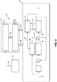
- Fig. 4 shows a flow diagram of a demand management and control system 40 for a gravity fed irrigation network 42 ( Fig. 5 ).
- the system 40 has a user interface 44 which allows customers to select a time frame and flow rate for valves 16, 18 and 20.
- Interface 44 can be a computer, keyboard or an Internet based application to allow the user to enter their requests 46 into system 40.
- the requests 46 and the returned confirmations to the user are monitored by a demand management system 48 implemented in a central computer 50.
- the demand management system 48 includes a real time database that maintains predetermined parameters including flow schedules, capabilities of valves, business and control rules.
- a supervisory layer 52 is also implemented in the central computer 50. Supervisory layer 52 is linked to the demand management system 48 through port 54 and updates and receives flow schedules and constraint information.
- Supervisory layer 52 communicates with each valve 16, 18 and 20 to cause the valves to be controlled through port 56 and to receive the measured flow and performance information through port 58.
- Each valve 16, 18 and 20 has a valve control interface 60 although Fig. 4 only shows one interface 60.
- Each valve control interface 60 can be in the form of a remote terminal unit (RTU) or programmable logic controller (PLC). It is evident that each valve will require a respective valve control interface.
- the location of the respective valve control interface(s) 60 can be with the central computer 50, or remotely located with the respective valve.
- Valve 16 is typically of the type shown in Figs. 17 to 79 of International Patent Application No. PCT/AU2012/000328 . Valve 16 will be associated with a flow meter (not shown), typically of the type shown in International Patent Application No. PCT/AU2010/001052 .
- the advantage of this type of valve is the approximately linear relationship between the valve opening (angular position) and flow. This ensures a relatively accurate flow setting is achieved using the predetermined valve opening.
- Other valve mechanisms such as butterfly valves that are commonly used in the water industry, do not possess this linear characteristic and would therefore have difficulty in achieving the required valve rating (to be described later) and the associated control.
- the preferred embodiment is not limited to these type of valves or flow meters but these valves and flow meters are well suited to the task.
- Each flow meter will provide the measured flow and performance information through port 58.
- Each valve 16 has a feed forward controller 62 and a feedback controller 64 whose outputs 66, 68 cause actuation of valve 16 via signal 69.
- the flow rate is measured by the flow meter (not shown) and sent to port 58, to feedback controller 64 through signal 71 and to a valve calibration section 70.
- the flow order 72 from port 56 for the valve 16 is delivered to both the feed forward controller 62 and the feedback controller 64.
- the feed forward controller 62 will lead the action of the feedback controller 64 using an optional delay switch 74. It is preferred that both the feed forward controller 62 and the feedback controller 64 be provided but the system can also function with only one of these controllers.
- Control strategy for low energy pipelines is one of managing the interactions of the controllers of each valve in a defined control methodology.
- Knowledge of the dynamics of the pipe 14 through the fluid network model will be used to design controllers using already well known classical control theory, and the knowledge of the future demand.
- the valve rating and measurement of the current pressure head conditions in the pipe 14 will be used to feed-forward to the valve 16 movements through controller 62.
- the valve rating is the derived relationship between;
- the valve rating will be calibrated during normal operation by the valve calibration section 70 using the data recorded for the aforementioned parameters during the normal operation of the valve 16.
- the valve rating is derived using System Identification techniques.
- the adjusted valve rating will be sent to valve 16 at 76 and the valve opening will be returned to valve calibration section 70 through signal 78.
- the valve rating allows a predetermined control action to send valve 16 to a particular opening for a known pressure head in order to achieve a desired flow.
- the valve rating facilitates a bulk control adjustment without relying on feedback control using the flow measurement.
- the system 40 provides control such that that hydraulic grade line is biased towards the high end of the spectrum.
- Fig. 6 it shows that valve 16 is operating and valves 18 and 20 are about to open.
- Fig. 6 graphically shows the static, as opposed to the dynamic, operation of the three valves.
- Valve 16 is due to stop at point 82 and valves 18 and 20 are to open at the same time.
- the closing event of valve 16 will be initiated first to make extra pressure head 90 available as can be seen from the accumulative pressure head line 88.
- the closing action of one or more valves will always lead (advance in time) any opening action of other valves.
- This control sequence ensures fluctuations in the pressure head (hydraulic grade line) due to control actions always result in a pressure greater than that predicted by the model and ensures that the pressure head does not drop below that predicted by the model within the demand management system 48. It is important the hydraulic grade line does not drop below a minimum supply level at valve as this can result in the pipe becoming "not full” and flow measurement would likely to be in error. In addition, maintaining the hydraulic grade line above a critical minimum level for valves is an important object of the low energy pipeline to guarantee an ordered flow can be achieved through the network. The command to deliver a flow at the valve will be provided by the demand management system 48 once the order passes the capacity checks.
- the feed-forward controller 62 kicks in first and moves the valve to a best estimate position to deliver the requested flow based on the local pressure head and valve rating.
- the feedback controller 64 only does the fine adjustments. In the preferred embodiment there will be an ability to use the feedback controller 64 or the feed forward controller 62 individually, or in combination as discussed previously. Such a methodology will minimize the transients in the pipeline and hence the interactions. This is a uniqueness of the solution.
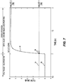
- Fig. 7 is a similar view to that of Fig. 3 showing the stable behaviour of the valves using the system shown in Fig. 4 .
- Line 24 illustrates valve 16 being already open and the effect that the opening of valve 18 has on the network.
- Line 26 illustrates the flow of valve 18. Both valves 16 and 18 are trying to maintain their preselected flow rate.
- the major jittery interaction shown in Fig. 3 at 30 has been substantially reduced in Fig. 7 using the system of this preferred embodiment.
- the jittery interaction show in Fig. 3 at 28 has also been substantially reduced. The improvement in control and steady flows through the valves even when multiple valves are operating is evident.
- the invention can also be used in association with irrigation system that include a hybrid pump for increasing the flow rate when an increase in flow rate is required.
- a hybrid pump for increasing the flow rate when an increase in flow rate is required.
- Such a system is shown in our Australian Patent Application Nos. 2012905225 and 2012905508 .
- Fig. 1 of these applications disclose a main pipeline 20 and a branch pipeline 30 that opens into main pipeline 20.
- the branch pipeline 30 has a low head lift pump 34 that provides an increased flow rate when required by the system.
- An inlet gate 22 on main pipeline 20 will be closed when pump 34 is operating.
- branch pipeline 30 is omitted and an inline pump 36 is provided in the main pipeline 20.
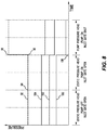
- FIG. 8 The graph shows pressure against time with line 92 showing the cumulative pressure head.
- the hybrid pump is turned on at point 94 but the pressure does not increase until the inlet gate is closed at point 96.
- the pressure will increase to the pressure shown at point 98.
- the increase in pressure will remain whilst the inlet gate is closed and the hybrid pump operates.
- Lines 100, 102 and 104 coincide with the movements of respective valves 20, 18 and 16. Valves 20, 18 and 16 are all open at point 106 at various flow rates and the system 40 will instruct the valves to adjust their valve openings to maintain their respective flow rates as the increased pressure from the hybrid pump is applied.
- the use of a hybrid pump will also have an impact on the hydraulic grade line when the pump is starting up or shutting down.
- the operation of the associated inlet gate (closing) at the pipe inlet allows for the gradual input of the raised pressure head from the pump. This would begin once the pump has been turned on. As the gate closes, the pressure head in the pipeline will increase. This will be undertaken gradually and potentially in a stepwise approach with corresponding offset (leading) valve adjustments occurring at each step. The step and the delay will be a function of the dynamics of the pipe such that valve interactions are kept to a minimum. Similarly the inlet gate could open gradually prior to the pump shutting down. The corresponding offset (lagging) valve adjustments would occur in a sequence with a stepwise opening of the inlet gate. Where there is a control objective to keep the hydraulic grade line below a particular maximum operating pressure the opening of a valve would lead the corresponding closing of another valve. The system would be programmed so that these circumstances can be identified and the appropriate control action taken.
- the supervisory layer 52 will monitor the performance of the pipe network 42 holistically and will have information about the topology.
- the supervisory layer 52 can include high level rules to operate the valves 16, 18, 20 to bias them towards a high pressure head, rules to mitigate the effects of interaction, and rules to follow during exception events. Interactions between controllers for each valve will be monitored by supervisory layer 52 through a further set of rules. Performance will be continuously monitored and deterioration in performance identified. An automatic rule based check will be performed to progressively turn off the feedback component of the valves in the network if control loop interaction is observed until the poorly performing valve is identified. Once identified, the poorly performing valve will have its control suspended, while the others will have the feedback turned back on.
Landscapes
- Engineering & Computer Science (AREA)
- Physics & Mathematics (AREA)
- General Physics & Mathematics (AREA)
- General Engineering & Computer Science (AREA)
- Automation & Control Theory (AREA)
- Theoretical Computer Science (AREA)
- Mechanical Engineering (AREA)
- Databases & Information Systems (AREA)
- Data Mining & Analysis (AREA)
- Mathematical Physics (AREA)
- Software Systems (AREA)
- Structural Engineering (AREA)
- Civil Engineering (AREA)
- Flow Control (AREA)
- Pipeline Systems (AREA)
Claims (14)
- Verfahren zur Bedarfsverwaltung und Steuerung eines Rohrnetzes (42); wobei das Rohrnetz ein computergesteuertes Fluidnetz mit begrenzter Druckhöhe oder Schwerkraftspeisung ist;
wobei das Rohrnetz mehrere Ventile (16, 18, 20) umfasst, durch die Fluid lieferbar ist;
die Ventile automatisiert sind, um gewünschte Flüsse durch die Ventile aufrecht zu erhalten;
wobei das Verfahren umfasstAufrechterhalten vorbestimmter Parameter, umfassend Flussablaufpläne und Fähigkeiten der mehreren Ventile, in einer Echtzeitdatenbasis innerhalb des computergesteuerten Fluidnetzes; undEmpfangen einer Anfrage für eine Lieferung des Fluids von mindestens einem (18) der Ventile durch eine Benutzerschnittstelle (44);wobei die Anfrage eine Flussrate und einen Lieferzeitpunkt umfasst;wobei das Verfahren ferner umfasstBestimmen unter Verwendung der vorbestimmten Parameter aus der Echtzeitdatenbasis, ob das Netzwerk eine hydraulische Kapazität aufweist, um die angeforderte Flussrate zu liefern; undwenn die hydraulische Kapazität verfügbar ist, Berechnen von Parametern unter Verwendung der Echtzeitdatenbasis zum Liefern des Fluids,Überwachen und einstellbares Steuern des mindestens einen Ventils und mindestens eines anderen (16) der mehreren Ventile, um die angefragt Flussrate zu liefern und die gewünschten Flüsse aufrecht zu erhalten und die Druckhöhe innerhalb des Fluidrohrnetzes zwischen vorbestimmten Grenzwerten zu halten;dadurch gekennzeichnet, dass das Verfahren ferner umfasst:Feinabstimmen der Position jedes der mehreren Ventile durch eine entsprechende Rückführsteuerung (64), die mit jedem der mehreren Ventile assoziiert ist;Variieren der Ventilpositionen jedes der mehreren Ventile durch eine entsprechende Vorsteuerung (62) auf eine erwartete Position, basierend auf einer überwachten Hydraulikkapazität des Rohrnetzes, einer vorausgesagten Druckhöhenänderung bei den jeweiligen Ventilen, basierend auf den Flussablaufplänen, die in der Echtzeitdatenbasis aufrechterhalten werden, und Ventilbewertungen, die mit dem jeweiligen Ventil assoziiert sind. - Verfahren nach Anspruch 1, umfassend das Bewegen mindestens eines anderen der mehreren Ventile in Erwartung einer Variation der Druckhöhe in dem Fluidrohrnetz aufgrund der Lieferung.
- Verfahren nach einem der vorhergehenden Ansprüche, ferner umfassend die Schritte um mehrerer Kunden zu erlauben, auf die Benutzerschnittstelle zuzugreifen; und
das computergesteuerte Fluidnetz eine Priorität und Gewichtung der Flussrate und Auslieferzeitanfragen des Fluids bestimmt, um die Kontinuität der hydraulischen Kapazität sicherzustellen. - Verfahren nach Anspruch 3, wobei die Priorität und Gewichtung der Lieferanfragen Tarifstrukturen für die Kunden, basierend auf einer besten Verwendung der verfügbaren hydraulischen Kapazität, umfassen.
- Verfahren nach einem der vorhergehenden Ansprüche, wobei Daten von einer Schnittstelle verwendet werden, um unter Verwendung eines Modells des Fluidrohrnetzes, basierend auf Systemidentifikationstechniken, das computergesteuerte Fluidnetz zu kalibrieren und kontinuierlich feinabzustimmen.
- Verfahren nach einem der vorhergehenden Ansprüche, ferner umfassend den Schritt zum Neuplanen der Flussrate und des Lieferzeitpunkts des Fluids durch das Fluidnetz, wenn die hydraulische Kapazität nicht bereitsteht.
- Verfahren nach einem der vorhergehenden Ansprüche, umfassend den Schritt des computergesteuerten Fluidnetzes zum Steuern eines Betriebs einer Hybridpumpe, um eine Druckhöhe aufrecht zu erhalten.
- Verfahren nach einem der vorhergehenden Ansprüche, wobei die mehreren Ventile doppelt faltbare Sperrelemente umfassen, die entlang einer zentralen Achse schwenken, um eine im Wesentlichen lineare Beziehung zwischen der Öffnung der doppelt faltbaren Sperrelemente und dem Fluidfluss herzustellen.
- Verfahren nach einem der vorhergehenden Ansprüche, wobei die vorbestimmten Parameter Geschäftsregeln und Beschränkungen umfassen, um weitere Variationen der Flussrate und des Lieferzeitpunkts des Fluids durch jedes Ventil zu erlauben.
- Verfahren nach einem der vorhergehenden Ansprüche, wobei jede nachfolgende Flussraten- und Lieferzeitanfrage, die in maximalen und minimalen Schwellenwerten der Flussgrenzwerte durch das Fluidnetz resultieren, die durchbrochen werden, verweigert oder neugeplant werden, um die nachfolgende Anfrage, basierend auf den berechneten Parametern, ausführen zu können.
- Verfahren nach einem der Ansprüche 1 bis 10, wobei die Anfrage eine Anfrage zur Bewässerung ist.
- Verfahren nach einem der Ansprüche 1 bis 11, wobei die vorbestimmten Grenzwerte der Druckhöhe nicht unter einen vorausgesagten Druck fallen, um das Rohrnetz voll zu halten.
- Ein Bedarfsmanagement- und Steuersystem (40) für ein Bedarfsmanagement und eine Steuerung eines Rohrnetzes (42);
wobei das Rohrnetz ein Fluidnetz mit einer begrenzten Druckhöhe oder Schwerkraftspeisung ist;
das Rohrnetz mehrere Ventile (16, 18, 20) umfasst, durch die Fluid lieferbar ist; die Ventile automatisiert sind, um gewünschte Flüsse durch die Ventile aufrecht zu erhalten;
das System einen Computer (50) umfasst, der eingerichtet ist zumAufrechterhalten vorbestimmter Parameter, umfassend Flussablaufpläne und Fähigkeiten der mehreren Ventile, in einer Echtzeitdatenbasis innerhalb des computergesteuerten Fluidnetzes; undEmpfangen einer Anfrage zur Lieferung des Fluids von mindestens einem (13) der Ventile durch eine Benutzerschnittstelle (44);wobei die Anfrage eine Flussrate und einen Lieferzeitpunkt umfasst;
der Computer ferner eingerichtet ist zumBestimmen unter Verwendung der vorbestimmten Parametern aus der Echtzeitdatenbasis, ob das Netz eine hydraulische Kapazität aufweist, um die angefragte Flussrate auszuliefern; undwenn die hydraulische Kapazität verfügbar ist, Überwachen und einstellbares Steuern des mindestens einen Ventils und mindestens eines anderen (16) der mehreren Ventile, um die angefragte Flussrate zu liefern und die gewünschten Flüsse aufrechtzuerhalten und die Druckhöhe innerhalb des Fluidrohrnetzes zwischen vorbestimmten Grenzwerten zu halten;dadurch gekennzeichnet, dass das Bedarfsverwaltungs- und Steuersystem ferner umfasst:eine entsprechende Rückführsteuerung (64), die mit jedem der mehreren Ventile assoziiert ist und eingerichtet ist die Position jedes der mehreren Ventile feinabzustimmen;eine entsprechende Vorsteuerung (62), die eingerichtet ist, die Ventilposition jedes der mehreren Ventile auf eine erwartete Position, basierend auf der überwachten hydraulischen Kapazität des Rohrnetzes einzustellen, Druckhöhenveränderungen bei den jeweiligen Ventilen vorauszusagen, basierend auf den Flussablaufplänen, die in der Echtzeitdatenbasis aufrechterhalten werden, und Ventilbewertungen, die mit dem jeweiligen Ventil assoziiert sind. - Fluidliefersystem (42, 50) umfassend das Bedarfsmanagement- und Steuersystem nach Anspruch 13 und das Rohrnetz.
Applications Claiming Priority (2)
| Application Number | Priority Date | Filing Date | Title |
|---|---|---|---|
| AU2013903383A AU2013903383A0 (en) | 2013-09-04 | Method of demand management and control of fluid pipe networks | |
| PCT/AU2014/050208 WO2015031954A1 (en) | 2013-09-04 | 2014-09-04 | Method of demand management and control of fluid pipe networks |
Publications (3)
| Publication Number | Publication Date |
|---|---|
| EP3041997A1 EP3041997A1 (de) | 2016-07-13 |
| EP3041997A4 EP3041997A4 (de) | 2017-04-19 |
| EP3041997B1 true EP3041997B1 (de) | 2020-01-22 |
Family
ID=52627619
Family Applications (1)
| Application Number | Title | Priority Date | Filing Date |
|---|---|---|---|
| EP14841712.4A Active EP3041997B1 (de) | 2013-09-04 | 2014-09-04 | Verfahren für bedarfsmanagement und steuerung von flüssigkeitsrohrleitungsnetzen |
Country Status (14)
| Country | Link |
|---|---|
| US (1) | US10114388B2 (de) |
| EP (1) | EP3041997B1 (de) |
| CN (2) | CN105612289A (de) |
| AU (1) | AU2014317812B2 (de) |
| BR (1) | BR112016004819B1 (de) |
| CA (1) | CA2922906C (de) |
| CL (1) | CL2016000491A1 (de) |
| EA (1) | EA032370B1 (de) |
| ES (1) | ES2786903T3 (de) |
| MA (1) | MA38924B1 (de) |
| MX (1) | MX371038B (de) |
| NZ (1) | NZ718357A (de) |
| PE (1) | PE20160346A1 (de) |
| WO (1) | WO2015031954A1 (de) |
Families Citing this family (12)
| Publication number | Priority date | Publication date | Assignee | Title |
|---|---|---|---|---|
| GB2545899B (en) * | 2015-12-21 | 2018-07-25 | Imperial Innovations Ltd | Management of liquid conduit systems |
| CN106647289B (zh) * | 2017-03-06 | 2019-09-10 | 武汉大学 | 明渠输水调度闸门延时启闭时间的前馈控制方法 |
| US9890908B1 (en) * | 2017-04-18 | 2018-02-13 | Air Products And Chemicals, Inc. | Control system in a gas pipeline network to increase capacity factor |
| US9915399B1 (en) | 2017-04-18 | 2018-03-13 | Air Products And Chemicals, Inc. | Control system in a gas pipeline network to satisfy demand constraints |
| US9897260B1 (en) | 2017-04-18 | 2018-02-20 | Air Products And Chemicals, Inc. | Control system in an industrial gas pipeline network to satisfy energy consumption constraints at production plants |
| US10415760B2 (en) | 2017-04-18 | 2019-09-17 | Air Products And Chemicals, Inc. | Control system in an industrial gas pipeline network to satisfy energy consumption constraints at production plants |
| US9897259B1 (en) | 2017-04-18 | 2018-02-20 | Air Products And Chemicals, Inc. | Control system in a gas pipeline network to satisfy pressure constraints |
| MX2020001738A (es) | 2017-08-14 | 2020-09-25 | Rubicon Res Pty Ltd | Procedimiento y sistema para distribución de agua y determinación de la humedad del suelo. |
| WO2020097534A1 (en) * | 2018-11-09 | 2020-05-14 | Schlumberger Technology Corporation | Pipeline network solving using decomposition procedure |
| ES3062061T3 (en) | 2019-07-26 | 2026-04-08 | Rubicon Res Pty Ltd | Multi pulley control gate |
| US12444189B2 (en) | 2021-12-14 | 2025-10-14 | Rubicon Research Pty Ltd | Methods and systems for classifying and benchmarking irrigation performance |
| CN115017666B (zh) * | 2022-08-08 | 2022-11-01 | 廊坊市清泉供水有限责任公司 | 地下水源地智能化运行方法及系统 |
Family Cites Families (20)
| Publication number | Priority date | Publication date | Assignee | Title |
|---|---|---|---|---|
| JPH09217900A (ja) | 1995-12-06 | 1997-08-19 | Hitachi Ltd | 流体輸送管網制御システム及び方法 |
| US5941305A (en) * | 1998-01-29 | 1999-08-24 | Patton Enterprises, Inc. | Real-time pump optimization system |
| WO2000063756A1 (en) * | 1999-04-16 | 2000-10-26 | Fujikin Incorporated | Parallel bypass type fluid feeding device, and method and device for controlling fluid variable type pressure system flow rate used for the device |
| US6568416B2 (en) * | 2001-02-28 | 2003-05-27 | Brian L. Andersen | Fluid flow control system, fluid delivery and control system for a fluid delivery line, and method for controlling pressure oscillations within fluid of a fluid delivery line |
| AUPR353801A0 (en) | 2001-03-02 | 2001-03-29 | Rubicon Systems Australia Pty Ltd | Fluid regulation |
| WO2004052560A2 (en) | 2002-12-10 | 2004-06-24 | Et Water Systems, Llc | Irrigation system |
| US7647136B2 (en) * | 2006-09-28 | 2010-01-12 | Exxonmobil Research And Engineering Company | Method and apparatus for enhancing operation of a fluid transport pipeline |
| BRPI0807862B8 (pt) | 2007-01-24 | 2023-01-31 | I2O Water Ltd | Controlador e sistema de controle para uma válvula redutora de pressão |
| GB0701352D0 (en) | 2007-01-24 | 2007-03-07 | Hydrodigital Ltd | Liquid pressure control |
| KR20090002115A (ko) * | 2007-06-18 | 2009-01-09 | 주식회사 케이티 | 광섬유 센서를 이용한 유량 측정과 네트워크를 통한 유류유통 서비스 시스템 및 방법 |
| BRPI0817076A2 (pt) * | 2007-09-06 | 2015-03-24 | Deka Products Lp | Sistema e método de processamento |
| US8406945B2 (en) | 2007-10-26 | 2013-03-26 | GM Global Technology Operations LLC | Method and apparatus to control logic valves for hydraulic flow control in an electro-mechanical transmission |
| JP4846749B2 (ja) * | 2008-03-11 | 2011-12-28 | 富士フイルム株式会社 | 記録テープカートリッジ |
| MX341582B (es) | 2009-08-18 | 2016-08-25 | Rubicon Res Pty Ltd | Ensamble de medidor de flujo, ensambles de compuerta y metodos para medicion de flujo. |
| CN101872161A (zh) * | 2010-04-30 | 2010-10-27 | 浙江大学 | 一种基于虚拟现实的流程工业重点装置交互控制方法 |
| CN101858095B (zh) * | 2010-06-10 | 2012-01-11 | 上海三高计算机中心股份有限公司 | 一种提供供水管网辅助调度数据的处理方法及装置 |
| CA3153748A1 (en) | 2011-04-01 | 2012-10-04 | Rubicon Research Pty Ltd | Actuation and valve mechanism |
| US9563207B2 (en) | 2011-08-02 | 2017-02-07 | Rubicon Research Pty Ltd | Demand management system for fluid networks |
| WO2013149304A1 (en) * | 2012-04-05 | 2013-10-10 | Rubicon Research Pty Ltd | Supervisory control of automated irrigation channels |
| CN107489888B (zh) | 2012-11-30 | 2020-05-01 | 鲁比康研究有限公司 | 流体管道系统 |
-
2014
- 2014-09-04 CN CN201480055328.1A patent/CN105612289A/zh active Pending
- 2014-09-04 MA MA38924A patent/MA38924B1/fr unknown
- 2014-09-04 MX MX2016002889A patent/MX371038B/es active IP Right Grant
- 2014-09-04 CA CA2922906A patent/CA2922906C/en active Active
- 2014-09-04 BR BR112016004819-9A patent/BR112016004819B1/pt active IP Right Grant
- 2014-09-04 WO PCT/AU2014/050208 patent/WO2015031954A1/en not_active Ceased
- 2014-09-04 EA EA201690426A patent/EA032370B1/ru unknown
- 2014-09-04 PE PE2016000341A patent/PE20160346A1/es unknown
- 2014-09-04 NZ NZ718357A patent/NZ718357A/en unknown
- 2014-09-04 AU AU2014317812A patent/AU2014317812B2/en active Active
- 2014-09-04 US US14/916,181 patent/US10114388B2/en active Active
- 2014-09-04 EP EP14841712.4A patent/EP3041997B1/de active Active
- 2014-09-04 CN CN201710785898.1A patent/CN107574785B/zh not_active Expired - Fee Related
- 2014-09-04 ES ES14841712T patent/ES2786903T3/es active Active
-
2016
- 2016-03-03 CL CL2016000491A patent/CL2016000491A1/es unknown
Non-Patent Citations (1)
| Title |
|---|
| None * |
Also Published As
| Publication number | Publication date |
|---|---|
| CN105612289A (zh) | 2016-05-25 |
| NZ718357A (en) | 2022-11-25 |
| US10114388B2 (en) | 2018-10-30 |
| MA38924B1 (fr) | 2017-09-29 |
| AU2014317812A1 (en) | 2016-04-21 |
| MA38924A1 (fr) | 2017-02-28 |
| CA2922906C (en) | 2021-06-08 |
| MX371038B (es) | 2020-01-14 |
| PE20160346A1 (es) | 2016-05-11 |
| CL2016000491A1 (es) | 2016-10-07 |
| EP3041997A4 (de) | 2017-04-19 |
| BR112016004819B1 (pt) | 2021-11-30 |
| EA201690426A1 (ru) | 2016-08-31 |
| BR112016004819A8 (pt) | 2020-02-11 |
| AU2014317812B2 (en) | 2017-08-31 |
| EA032370B1 (ru) | 2019-05-31 |
| WO2015031954A1 (en) | 2015-03-12 |
| CA2922906A1 (en) | 2015-03-12 |
| US20160209851A1 (en) | 2016-07-21 |
| CN107574785B (zh) | 2021-06-18 |
| CN107574785A (zh) | 2018-01-12 |
| MX2016002889A (es) | 2016-07-05 |
| EP3041997A1 (de) | 2016-07-13 |
| ES2786903T3 (es) | 2020-10-14 |
Similar Documents
| Publication | Publication Date | Title |
|---|---|---|
| EP3041997B1 (de) | Verfahren für bedarfsmanagement und steuerung von flüssigkeitsrohrleitungsnetzen | |
| EP2740063B1 (de) | Bedarfsverwaltungssystem für fluidnetzwerke | |
| EP2834714B1 (de) | Überwachungssteuerung für automatische bewässerungskanäle | |
| Giustolisi et al. | Strategies for the electric regulation of pressure control valves | |
| MX2007013902A (es) | Metodo y sistema para mejorar el control de linea de flujo. | |
| CN102239359B (zh) | 气体供给方法 | |
| Xu | Model predictive control of an irrigation canal using dynamic target trajectory | |
| JP3959935B2 (ja) | 流量制御装置及び方法 | |
| Evans et al. | Real-time optimal control of river basin networks | |
| Clemmens et al. | Application of software for automatic canal management (SacMan) to the WM lateral canal | |
| JP6477268B2 (ja) | 流量制御装置、流量制御システム、流量制御プログラム、及び流量制御方法 | |
| JP2013253651A (ja) | 液化ガス払出設備 | |
| JP7823843B2 (ja) | 流量制御装置の排気構造、排気方法及びそれを備えたガス供給システム及びガス供給方法 | |
| JPH01251211A (ja) | 配水管網制御装置 | |
| Bibok et al. | Hydraulic model calibration of pressure reduced zones with multiple input valves | |
| Letunov et al. | Application of Proportional, Integral, Derivative PID Control Loop Algorithm for Optimization of Equipment Operation Used for Decentralized Water Injection System at West Qurna 2 Oilfield | |
| JPH02268305A (ja) | 配水管網制御装置 | |
| Clemmens | Progress on canal automation for water delivery modernization | |
| Inderfurth | Risk and safety stock management in production planning and inventory control with stochastic demand and yield | |
| JP2004295567A (ja) | ガス供給方法 |
Legal Events
| Date | Code | Title | Description |
|---|---|---|---|
| PUAI | Public reference made under article 153(3) epc to a published international application that has entered the european phase |
Free format text: ORIGINAL CODE: 0009012 |
|
| 17P | Request for examination filed |
Effective date: 20160330 |
|
| AK | Designated contracting states |
Kind code of ref document: A1 Designated state(s): AL AT BE BG CH CY CZ DE DK EE ES FI FR GB GR HR HU IE IS IT LI LT LU LV MC MK MT NL NO PL PT RO RS SE SI SK SM TR |
|
| AX | Request for extension of the european patent |
Extension state: BA ME |
|
| DAX | Request for extension of the european patent (deleted) | ||
| REG | Reference to a national code |
Ref country code: DE Ref legal event code: R079 Ref document number: 602014060455 Country of ref document: DE Free format text: PREVIOUS MAIN CLASS: E02B0001000000 Ipc: E02B0013000000 |
|
| A4 | Supplementary search report drawn up and despatched |
Effective date: 20170322 |
|
| RIC1 | Information provided on ipc code assigned before grant |
Ipc: E02B 13/00 20060101AFI20170316BHEP Ipc: G05D 7/06 20060101ALI20170316BHEP Ipc: G05B 19/00 20060101ALI20170316BHEP Ipc: F17D 1/00 20060101ALI20170316BHEP |
|
| STAA | Information on the status of an ep patent application or granted ep patent |
Free format text: STATUS: EXAMINATION IS IN PROGRESS |
|
| 17Q | First examination report despatched |
Effective date: 20190208 |
|
| GRAP | Despatch of communication of intention to grant a patent |
Free format text: ORIGINAL CODE: EPIDOSNIGR1 |
|
| STAA | Information on the status of an ep patent application or granted ep patent |
Free format text: STATUS: GRANT OF PATENT IS INTENDED |
|
| RAP1 | Party data changed (applicant data changed or rights of an application transferred) |
Owner name: RUBICON RESEARCH PTY LTD. |
|
| RIN1 | Information on inventor provided before grant (corrected) |
Inventor name: CHOY, SUMITH Inventor name: AUGHTON, DAVID, JOHN |
|
| INTG | Intention to grant announced |
Effective date: 20190920 |
|
| GRAS | Grant fee paid |
Free format text: ORIGINAL CODE: EPIDOSNIGR3 |
|
| GRAA | (expected) grant |
Free format text: ORIGINAL CODE: 0009210 |
|
| STAA | Information on the status of an ep patent application or granted ep patent |
Free format text: STATUS: THE PATENT HAS BEEN GRANTED |
|
| RAP1 | Party data changed (applicant data changed or rights of an application transferred) |
Owner name: RUBICON RESEARCH PTY LTD. |
|
| AK | Designated contracting states |
Kind code of ref document: B1 Designated state(s): AL AT BE BG CH CY CZ DE DK EE ES FI FR GB GR HR HU IE IS IT LI LT LU LV MC MK MT NL NO PL PT RO RS SE SI SK SM TR |
|
| REG | Reference to a national code |
Ref country code: GB Ref legal event code: FG4D |
|
| REG | Reference to a national code |
Ref country code: CH Ref legal event code: EP |
|
| REG | Reference to a national code |
Ref country code: AT Ref legal event code: REF Ref document number: 1226976 Country of ref document: AT Kind code of ref document: T Effective date: 20200215 |
|
| REG | Reference to a national code |
Ref country code: IE Ref legal event code: FG4D |
|
| REG | Reference to a national code |
Ref country code: DE Ref legal event code: R096 Ref document number: 602014060455 Country of ref document: DE |
|
| REG | Reference to a national code |
Ref country code: RO Ref legal event code: EPE |
|
| REG | Reference to a national code |
Ref country code: NL Ref legal event code: MP Effective date: 20200122 |
|
| REG | Reference to a national code |
Ref country code: LT Ref legal event code: MG4D |
|
| PG25 | Lapsed in a contracting state [announced via postgrant information from national office to epo] |
Ref country code: RS Free format text: LAPSE BECAUSE OF FAILURE TO SUBMIT A TRANSLATION OF THE DESCRIPTION OR TO PAY THE FEE WITHIN THE PRESCRIBED TIME-LIMIT Effective date: 20200122 Ref country code: NL Free format text: LAPSE BECAUSE OF FAILURE TO SUBMIT A TRANSLATION OF THE DESCRIPTION OR TO PAY THE FEE WITHIN THE PRESCRIBED TIME-LIMIT Effective date: 20200122 Ref country code: FI Free format text: LAPSE BECAUSE OF FAILURE TO SUBMIT A TRANSLATION OF THE DESCRIPTION OR TO PAY THE FEE WITHIN THE PRESCRIBED TIME-LIMIT Effective date: 20200122 Ref country code: PT Free format text: LAPSE BECAUSE OF FAILURE TO SUBMIT A TRANSLATION OF THE DESCRIPTION OR TO PAY THE FEE WITHIN THE PRESCRIBED TIME-LIMIT Effective date: 20200614 Ref country code: NO Free format text: LAPSE BECAUSE OF FAILURE TO SUBMIT A TRANSLATION OF THE DESCRIPTION OR TO PAY THE FEE WITHIN THE PRESCRIBED TIME-LIMIT Effective date: 20200422 |
|
| PG25 | Lapsed in a contracting state [announced via postgrant information from national office to epo] |
Ref country code: SE Free format text: LAPSE BECAUSE OF FAILURE TO SUBMIT A TRANSLATION OF THE DESCRIPTION OR TO PAY THE FEE WITHIN THE PRESCRIBED TIME-LIMIT Effective date: 20200122 Ref country code: LV Free format text: LAPSE BECAUSE OF FAILURE TO SUBMIT A TRANSLATION OF THE DESCRIPTION OR TO PAY THE FEE WITHIN THE PRESCRIBED TIME-LIMIT Effective date: 20200122 Ref country code: BG Free format text: LAPSE BECAUSE OF FAILURE TO SUBMIT A TRANSLATION OF THE DESCRIPTION OR TO PAY THE FEE WITHIN THE PRESCRIBED TIME-LIMIT Effective date: 20200422 Ref country code: IS Free format text: LAPSE BECAUSE OF FAILURE TO SUBMIT A TRANSLATION OF THE DESCRIPTION OR TO PAY THE FEE WITHIN THE PRESCRIBED TIME-LIMIT Effective date: 20200522 Ref country code: GR Free format text: LAPSE BECAUSE OF FAILURE TO SUBMIT A TRANSLATION OF THE DESCRIPTION OR TO PAY THE FEE WITHIN THE PRESCRIBED TIME-LIMIT Effective date: 20200423 Ref country code: HR Free format text: LAPSE BECAUSE OF FAILURE TO SUBMIT A TRANSLATION OF THE DESCRIPTION OR TO PAY THE FEE WITHIN THE PRESCRIBED TIME-LIMIT Effective date: 20200122 |
|
| REG | Reference to a national code |
Ref country code: ES Ref legal event code: FG2A Ref document number: 2786903 Country of ref document: ES Kind code of ref document: T3 Effective date: 20201014 |
|
| REG | Reference to a national code |
Ref country code: DE Ref legal event code: R097 Ref document number: 602014060455 Country of ref document: DE |
|
| PG25 | Lapsed in a contracting state [announced via postgrant information from national office to epo] |
Ref country code: SK Free format text: LAPSE BECAUSE OF FAILURE TO SUBMIT A TRANSLATION OF THE DESCRIPTION OR TO PAY THE FEE WITHIN THE PRESCRIBED TIME-LIMIT Effective date: 20200122 Ref country code: SM Free format text: LAPSE BECAUSE OF FAILURE TO SUBMIT A TRANSLATION OF THE DESCRIPTION OR TO PAY THE FEE WITHIN THE PRESCRIBED TIME-LIMIT Effective date: 20200122 Ref country code: DK Free format text: LAPSE BECAUSE OF FAILURE TO SUBMIT A TRANSLATION OF THE DESCRIPTION OR TO PAY THE FEE WITHIN THE PRESCRIBED TIME-LIMIT Effective date: 20200122 Ref country code: EE Free format text: LAPSE BECAUSE OF FAILURE TO SUBMIT A TRANSLATION OF THE DESCRIPTION OR TO PAY THE FEE WITHIN THE PRESCRIBED TIME-LIMIT Effective date: 20200122 Ref country code: LT Free format text: LAPSE BECAUSE OF FAILURE TO SUBMIT A TRANSLATION OF THE DESCRIPTION OR TO PAY THE FEE WITHIN THE PRESCRIBED TIME-LIMIT Effective date: 20200122 Ref country code: CZ Free format text: LAPSE BECAUSE OF FAILURE TO SUBMIT A TRANSLATION OF THE DESCRIPTION OR TO PAY THE FEE WITHIN THE PRESCRIBED TIME-LIMIT Effective date: 20200122 |
|
| REG | Reference to a national code |
Ref country code: AT Ref legal event code: MK05 Ref document number: 1226976 Country of ref document: AT Kind code of ref document: T Effective date: 20200122 |
|
| PLBE | No opposition filed within time limit |
Free format text: ORIGINAL CODE: 0009261 |
|
| STAA | Information on the status of an ep patent application or granted ep patent |
Free format text: STATUS: NO OPPOSITION FILED WITHIN TIME LIMIT |
|
| 26N | No opposition filed |
Effective date: 20201023 |
|
| PG25 | Lapsed in a contracting state [announced via postgrant information from national office to epo] |
Ref country code: AT Free format text: LAPSE BECAUSE OF FAILURE TO SUBMIT A TRANSLATION OF THE DESCRIPTION OR TO PAY THE FEE WITHIN THE PRESCRIBED TIME-LIMIT Effective date: 20200122 |
|
| PG25 | Lapsed in a contracting state [announced via postgrant information from national office to epo] |
Ref country code: SI Free format text: LAPSE BECAUSE OF FAILURE TO SUBMIT A TRANSLATION OF THE DESCRIPTION OR TO PAY THE FEE WITHIN THE PRESCRIBED TIME-LIMIT Effective date: 20200122 Ref country code: PL Free format text: LAPSE BECAUSE OF FAILURE TO SUBMIT A TRANSLATION OF THE DESCRIPTION OR TO PAY THE FEE WITHIN THE PRESCRIBED TIME-LIMIT Effective date: 20200122 |
|
| REG | Reference to a national code |
Ref country code: DE Ref legal event code: R119 Ref document number: 602014060455 Country of ref document: DE |
|
| PG25 | Lapsed in a contracting state [announced via postgrant information from national office to epo] |
Ref country code: MC Free format text: LAPSE BECAUSE OF FAILURE TO SUBMIT A TRANSLATION OF THE DESCRIPTION OR TO PAY THE FEE WITHIN THE PRESCRIBED TIME-LIMIT Effective date: 20200122 |
|
| REG | Reference to a national code |
Ref country code: CH Ref legal event code: PL |
|
| GBPC | Gb: european patent ceased through non-payment of renewal fee |
Effective date: 20200904 |
|
| REG | Reference to a national code |
Ref country code: BE Ref legal event code: MM Effective date: 20200930 |
|
| PG25 | Lapsed in a contracting state [announced via postgrant information from national office to epo] |
Ref country code: LU Free format text: LAPSE BECAUSE OF NON-PAYMENT OF DUE FEES Effective date: 20200904 |
|
| PG25 | Lapsed in a contracting state [announced via postgrant information from national office to epo] |
Ref country code: DE Free format text: LAPSE BECAUSE OF NON-PAYMENT OF DUE FEES Effective date: 20210401 Ref country code: FR Free format text: LAPSE BECAUSE OF NON-PAYMENT OF DUE FEES Effective date: 20200930 |
|
| PG25 | Lapsed in a contracting state [announced via postgrant information from national office to epo] |
Ref country code: IE Free format text: LAPSE BECAUSE OF NON-PAYMENT OF DUE FEES Effective date: 20200904 Ref country code: GB Free format text: LAPSE BECAUSE OF NON-PAYMENT OF DUE FEES Effective date: 20200904 Ref country code: CH Free format text: LAPSE BECAUSE OF NON-PAYMENT OF DUE FEES Effective date: 20200930 Ref country code: BE Free format text: LAPSE BECAUSE OF NON-PAYMENT OF DUE FEES Effective date: 20200930 Ref country code: LI Free format text: LAPSE BECAUSE OF NON-PAYMENT OF DUE FEES Effective date: 20200930 |
|
| PG25 | Lapsed in a contracting state [announced via postgrant information from national office to epo] |
Ref country code: TR Free format text: LAPSE BECAUSE OF FAILURE TO SUBMIT A TRANSLATION OF THE DESCRIPTION OR TO PAY THE FEE WITHIN THE PRESCRIBED TIME-LIMIT Effective date: 20200122 Ref country code: MT Free format text: LAPSE BECAUSE OF FAILURE TO SUBMIT A TRANSLATION OF THE DESCRIPTION OR TO PAY THE FEE WITHIN THE PRESCRIBED TIME-LIMIT Effective date: 20200122 Ref country code: CY Free format text: LAPSE BECAUSE OF FAILURE TO SUBMIT A TRANSLATION OF THE DESCRIPTION OR TO PAY THE FEE WITHIN THE PRESCRIBED TIME-LIMIT Effective date: 20200122 |
|
| PG25 | Lapsed in a contracting state [announced via postgrant information from national office to epo] |
Ref country code: MK Free format text: LAPSE BECAUSE OF FAILURE TO SUBMIT A TRANSLATION OF THE DESCRIPTION OR TO PAY THE FEE WITHIN THE PRESCRIBED TIME-LIMIT Effective date: 20200122 Ref country code: AL Free format text: LAPSE BECAUSE OF FAILURE TO SUBMIT A TRANSLATION OF THE DESCRIPTION OR TO PAY THE FEE WITHIN THE PRESCRIBED TIME-LIMIT Effective date: 20200122 |
|
| P01 | Opt-out of the competence of the unified patent court (upc) registered |
Effective date: 20230602 |
|
| PGFP | Annual fee paid to national office [announced via postgrant information from national office to epo] |
Ref country code: RO Payment date: 20230904 Year of fee payment: 10 |
|
| PG25 | Lapsed in a contracting state [announced via postgrant information from national office to epo] |
Ref country code: RO Free format text: LAPSE BECAUSE OF NON-PAYMENT OF DUE FEES Effective date: 20240904 |
|
| PGFP | Annual fee paid to national office [announced via postgrant information from national office to epo] |
Ref country code: IT Payment date: 20250929 Year of fee payment: 12 |
|
| PGFP | Annual fee paid to national office [announced via postgrant information from national office to epo] |
Ref country code: ES Payment date: 20251205 Year of fee payment: 12 |