EP3041379B1 - Method of forming an article of footwear incorporating a knitted upper with tensile strand - Google Patents
Method of forming an article of footwear incorporating a knitted upper with tensile strand Download PDFInfo
- Publication number
- EP3041379B1 EP3041379B1 EP14741724.0A EP14741724A EP3041379B1 EP 3041379 B1 EP3041379 B1 EP 3041379B1 EP 14741724 A EP14741724 A EP 14741724A EP 3041379 B1 EP3041379 B1 EP 3041379B1
- Authority
- EP
- European Patent Office
- Prior art keywords
- workpiece
- layer
- knitted
- footwear
- knit element
- Prior art date
- Legal status (The legal status is an assumption and is not a legal conclusion. Google has not performed a legal analysis and makes no representation as to the accuracy of the status listed.)
- Active
Links
- 238000000034 method Methods 0.000 title claims description 54
- 238000009940 knitting Methods 0.000 claims description 20
- 238000010276 construction Methods 0.000 claims description 13
- 238000009966 trimming Methods 0.000 claims description 13
- 238000007373 indentation Methods 0.000 claims description 9
- 238000010438 heat treatment Methods 0.000 claims 4
- 210000002683 foot Anatomy 0.000 description 62
- 210000000474 heel Anatomy 0.000 description 21
- 210000004744 fore-foot Anatomy 0.000 description 15
- 239000000463 material Substances 0.000 description 14
- 210000000452 mid-foot Anatomy 0.000 description 11
- 238000004519 manufacturing process Methods 0.000 description 10
- 239000011800 void material Substances 0.000 description 10
- 241000237503 Pectinidae Species 0.000 description 8
- 235000020637 scallop Nutrition 0.000 description 8
- 210000003423 ankle Anatomy 0.000 description 5
- 229920000642 polymer Polymers 0.000 description 5
- 229920001169 thermoplastic Polymers 0.000 description 5
- 230000000386 athletic effect Effects 0.000 description 4
- 239000006260 foam Substances 0.000 description 4
- 230000033001 locomotion Effects 0.000 description 4
- 239000002861 polymer material Substances 0.000 description 4
- 239000003086 colorant Substances 0.000 description 3
- 239000010985 leather Substances 0.000 description 3
- 239000002649 leather substitute Substances 0.000 description 3
- 239000007787 solid Substances 0.000 description 3
- 239000000853 adhesive Substances 0.000 description 2
- 230000001070 adhesive effect Effects 0.000 description 2
- 238000005520 cutting process Methods 0.000 description 2
- 230000000694 effects Effects 0.000 description 2
- 229920001971 elastomer Polymers 0.000 description 2
- 239000012530 fluid Substances 0.000 description 2
- 239000007788 liquid Substances 0.000 description 2
- 230000035699 permeability Effects 0.000 description 2
- 230000000704 physical effect Effects 0.000 description 2
- 239000004753 textile Substances 0.000 description 2
- 210000003371 toe Anatomy 0.000 description 2
- 230000007704 transition Effects 0.000 description 2
- 229920000742 Cotton Polymers 0.000 description 1
- 239000004677 Nylon Substances 0.000 description 1
- 229920000297 Rayon Polymers 0.000 description 1
- 229920002334 Spandex Polymers 0.000 description 1
- 230000015572 biosynthetic process Effects 0.000 description 1
- 210000000459 calcaneus Anatomy 0.000 description 1
- 238000001816 cooling Methods 0.000 description 1
- 230000001351 cycling effect Effects 0.000 description 1
- 230000001419 dependent effect Effects 0.000 description 1
- 238000013461 design Methods 0.000 description 1
- 238000010586 diagram Methods 0.000 description 1
- 238000001035 drying Methods 0.000 description 1
- 238000004049 embossing Methods 0.000 description 1
- BFMKFCLXZSUVPI-UHFFFAOYSA-N ethyl but-3-enoate Chemical compound CCOC(=O)CC=C BFMKFCLXZSUVPI-UHFFFAOYSA-N 0.000 description 1
- 239000006261 foam material Substances 0.000 description 1
- 239000011888 foil Substances 0.000 description 1
- 238000003780 insertion Methods 0.000 description 1
- 230000037431 insertion Effects 0.000 description 1
- 230000002045 lasting effect Effects 0.000 description 1
- 230000013011 mating Effects 0.000 description 1
- 239000000155 melt Substances 0.000 description 1
- 239000002184 metal Substances 0.000 description 1
- 210000001872 metatarsal bone Anatomy 0.000 description 1
- 229920001778 nylon Polymers 0.000 description 1
- 229920000728 polyester Polymers 0.000 description 1
- 229920002635 polyurethane Polymers 0.000 description 1
- 239000004814 polyurethane Substances 0.000 description 1
- 239000002964 rayon Substances 0.000 description 1
- 238000007789 sealing Methods 0.000 description 1
- 230000009192 sprinting Effects 0.000 description 1
- 239000004416 thermosoftening plastic Substances 0.000 description 1
- 238000012549 training Methods 0.000 description 1
- 238000012546 transfer Methods 0.000 description 1
- -1 wool Polymers 0.000 description 1
- 210000002268 wool Anatomy 0.000 description 1
Images


Classifications
-
- A—HUMAN NECESSITIES
- A43—FOOTWEAR
- A43B—CHARACTERISTIC FEATURES OF FOOTWEAR; PARTS OF FOOTWEAR
- A43B1/00—Footwear characterised by the material
- A43B1/02—Footwear characterised by the material made of fibres or fabrics made therefrom
- A43B1/04—Footwear characterised by the material made of fibres or fabrics made therefrom braided, knotted, knitted or crocheted
-
- A—HUMAN NECESSITIES
- A43—FOOTWEAR
- A43B—CHARACTERISTIC FEATURES OF FOOTWEAR; PARTS OF FOOTWEAR
- A43B23/00—Uppers; Boot legs; Stiffeners; Other single parts of footwear
- A43B23/02—Uppers; Boot legs
- A43B23/0205—Uppers; Boot legs characterised by the material
- A43B23/0235—Different layers of different material
-
- A—HUMAN NECESSITIES
- A43—FOOTWEAR
- A43B—CHARACTERISTIC FEATURES OF FOOTWEAR; PARTS OF FOOTWEAR
- A43B23/00—Uppers; Boot legs; Stiffeners; Other single parts of footwear
- A43B23/02—Uppers; Boot legs
- A43B23/0245—Uppers; Boot legs characterised by the constructive form
- A43B23/0255—Uppers; Boot legs characterised by the constructive form assembled by gluing or thermo bonding
-
- A—HUMAN NECESSITIES
- A43—FOOTWEAR
- A43B—CHARACTERISTIC FEATURES OF FOOTWEAR; PARTS OF FOOTWEAR
- A43B23/00—Uppers; Boot legs; Stiffeners; Other single parts of footwear
- A43B23/02—Uppers; Boot legs
- A43B23/0245—Uppers; Boot legs characterised by the constructive form
- A43B23/0265—Uppers; Boot legs characterised by the constructive form having different properties in different directions
- A43B23/0275—Uppers; Boot legs characterised by the constructive form having different properties in different directions with a part of the upper particularly rigid, e.g. resisting articulation or torsion
-
- D—TEXTILES; PAPER
- D04—BRAIDING; LACE-MAKING; KNITTING; TRIMMINGS; NON-WOVEN FABRICS
- D04B—KNITTING
- D04B1/00—Weft knitting processes for the production of fabrics or articles not dependent on the use of particular machines; Fabrics or articles defined by such processes
- D04B1/10—Patterned fabrics or articles
- D04B1/102—Patterned fabrics or articles with stitch pattern
- D04B1/106—Patterned fabrics or articles with stitch pattern at a selvedge, e.g. hems or turned welts
-
- D—TEXTILES; PAPER
- D04—BRAIDING; LACE-MAKING; KNITTING; TRIMMINGS; NON-WOVEN FABRICS
- D04B—KNITTING
- D04B1/00—Weft knitting processes for the production of fabrics or articles not dependent on the use of particular machines; Fabrics or articles defined by such processes
- D04B1/10—Patterned fabrics or articles
- D04B1/12—Patterned fabrics or articles characterised by thread material
- D04B1/123—Patterned fabrics or articles characterised by thread material with laid-in unlooped yarn, e.g. fleece fabrics
-
- A—HUMAN NECESSITIES
- A43—FOOTWEAR
- A43B—CHARACTERISTIC FEATURES OF FOOTWEAR; PARTS OF FOOTWEAR
- A43B23/00—Uppers; Boot legs; Stiffeners; Other single parts of footwear
- A43B23/02—Uppers; Boot legs
- A43B23/0245—Uppers; Boot legs characterised by the constructive form
-
- A—HUMAN NECESSITIES
- A43—FOOTWEAR
- A43B—CHARACTERISTIC FEATURES OF FOOTWEAR; PARTS OF FOOTWEAR
- A43B3/00—Footwear characterised by the shape or the use
- A43B3/26—Footwear characterised by the shape or the use adjustable as to length or size
-
- D—TEXTILES; PAPER
- D10—INDEXING SCHEME ASSOCIATED WITH SUBLASSES OF SECTION D, RELATING TO TEXTILES
- D10B—INDEXING SCHEME ASSOCIATED WITH SUBLASSES OF SECTION D, RELATING TO TEXTILES
- D10B2403/00—Details of fabric structure established in the fabric forming process
- D10B2403/01—Surface features
- D10B2403/011—Dissimilar front and back faces
- D10B2403/0112—One smooth surface, e.g. laminated or coated
-
- D—TEXTILES; PAPER
- D10—INDEXING SCHEME ASSOCIATED WITH SUBLASSES OF SECTION D, RELATING TO TEXTILES
- D10B—INDEXING SCHEME ASSOCIATED WITH SUBLASSES OF SECTION D, RELATING TO TEXTILES
- D10B2403/00—Details of fabric structure established in the fabric forming process
- D10B2403/03—Shape features
- D10B2403/032—Flat fabric of variable width, e.g. including one or more fashioned panels
-
- D—TEXTILES; PAPER
- D10—INDEXING SCHEME ASSOCIATED WITH SUBLASSES OF SECTION D, RELATING TO TEXTILES
- D10B—INDEXING SCHEME ASSOCIATED WITH SUBLASSES OF SECTION D, RELATING TO TEXTILES
- D10B2501/00—Wearing apparel
- D10B2501/04—Outerwear; Protective garments
- D10B2501/043—Footwear
Definitions
- Conventional articles of footwear generally include two primary elements: an upper and a sole structure.
- the upper is secured to the sole structure and forms a void within the footwear for comfortably and securely receiving a foot.
- the sole structure is secured to a lower surface of the upper so as to be positioned between the upper and the ground.
- the sole structure may include a midsole and an outsole.
- the midsole may be formed from a polymer foam material that attenuates ground reaction forces to lessen stresses upon the foot and leg during walking, running, and other ambulatory activities.
- the outsole is secured to a lower surface of the midsole and forms a ground-engaging portion of the sole structure that is formed from a durable and wear-resistant material.
- the sole structure may also include a sockliner positioned within the void and proximal a lower surface of the foot to enhance footwear comfort.
- the upper can extend over the instep and toe areas of the foot, along the medial and lateral sides of the foot, and around the heel area of the foot.
- the upper may extend upward and around the ankle to provide support or protection for the ankle.
- Access to the void on the interior of the upper is generally provided by an ankle opening in a heel region of the footwear.
- a lacing system is often incorporated into the upper to adjust the fit of the upper, thereby permitting entry and removal of the foot from the void within the upper.
- the lacing system also permits the wearer to modify certain dimensions of the upper, particularly girth, to accommodate feet with varying dimensions.
- the upper may include a footwear, and the upper may incorporate a heel counter to limit movement of the heel.
- the upper of athletic footwear may be formed from multiple material elements.
- the materials may be selected based upon various properties, including stretch-resistance, wear-resistance, flexibility, air-permeability, compressibility, and moisture-wicking, for example.
- the upper may be formed of leather, synthetic leather, or a rubber material.
- the upper may be formed from numerous material elements that each imparts different properties to the upper.
- WO 9003744 A1 discloses a labor-saving shoe making process that provides multilayered, heat embossed, shoe components including a one-piece upper.
- the components comprise a resilient foam layer and other layers for flexibility, strength and durability. Embossing of the shoe components serves to reduce the thickness of the material, provide sealing of the material, provide form and shape to the shoe, and allow strain control management.
- the connecting of shoe components is accomplished in part through the use of thermoplastic rivets which are heated and melted by the application of a high frequency field.
- a workpiece configured for forming one of a first upper for a first article of footwear and a second upper for a second article of footwear according to the invention is defined in Claim 10.
- the first upper and the first article of footwear are configured to fit to a first foot size
- the second upper and the second article of footwear are configured to fit to a second foot size.
- the workpiece includes a knitted component having a knit element and a tensile strand that are formed of unitary knit construction.
- the knitted component is configured to at least partially form one of the first upper and the second upper.
- the knit element defines a body and a trim region, and the trim region defines an outer edge of the knit element.
- the tensile strand includes at least one inlaid portion that is inlaid within the knit element, and the tensile strand also includes an exposed portion that is exposed from the knit element and that is disposed adjacent the outer edge. The exposed portion is spaced from the outer edge in an inboard direction on the knit element. The exposed portion is configured to be manipulated to thereby move and adjust the inlaid portion relative to the knit element. Also, the trim region is trimmable along one of a first trim line to form the first upper and a second trim line to form the second upper, wherein the first trim line and the second trim line are indicated and visually apparent on the workpiece.
- the upper can be formed from a knitted workpiece that is trimmed down to a predetermined size to fit a particular anatomical foot size. This can increase manufacturing efficiency and provide additional advantages as will be explained in greater detail below.
- the article of footwear is disclosed as having a general configuration suitable for walking or running.
- Concepts associated with the footwear, including the upper may also be applied to a variety of other athletic footwear types, including soccer shoes, baseball shoes, basketball shoes, cross-training shoes, cycling shoes, football shoes, sprinting shoes, tennis shoes, and hiking boots, for example.
- the concepts may also be applied to footwear types that are generally considered to be non-athletic, including dress shoes, loafers, sandals, and work boots.
- the concepts disclosed herein apply, therefore, to a wide variety of footwear types.
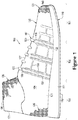
- FIGS. 1-4 An article of footwear 100 is depicted in FIGS. 1-4 as including a sole structure 110 and an upper 120.
- sole structure 110 is located under and supports a foot of a wearer
- upper 120 provides a comfortable and secure covering for the foot.
- the foot may be located within a void in upper 120 to effectively secure the foot within footwear 100 or otherwise unite the foot and footwear 100.
- sole structure 110 is secured to a lower area of upper 120 and extends between the foot and the ground to attenuate ground reaction forces (i.e., cushion the foot), provide traction, enhance stability, and influence the motions of the foot, for example.
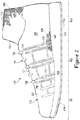
- footwear 100 may be divided into three general regions: a forefoot region 101, a midfoot region 102, and a heel region 103.
- Forefoot region 101 generally encompasses portions of footwear 100 corresponding with forward portions of the foot, including the toes and joints connecting the metatarsals with the phalanges.
- Midfoot region 102 generally encompasses portions of footwear 100 corresponding with middle portions of the foot, including an arch area.
- Heel region 103 generally encompasses portions of footwear 100 corresponding with rear portions of the foot, including the heel and calcaneus bone.
- Footwear 100 also includes a lateral side 104 and a medial side 105, which extend through forefoot region 101, midfoot region 102, and heel region 103, and which correspond with opposite sides of footwear 100. More particularly, lateral side 104 corresponds with an outside area of the foot (i.e. the surface that faces away from the other foot), and medial side 105 corresponds with an inside area of the foot (i.e., the surface that faces toward the other foot). Forefoot region 101, midfoot region 102, heel region 103, lateral side 104, and medial side 105 are not intended to demarcate precise areas of footwear 100.
- forefoot region 101, midfoot region 102, heel region 103, lateral side 104, and medial side 105 are intended to represent general areas of footwear 100 to aid in the following discussion.
- forefoot region 101, midfoot region 102, heel region 103, lateral side 104, and medial side 105 may also be applied to sole structure 110, upper 120, and individual elements thereof.
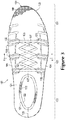
- Sole structure 110 can include a midsole 111, an outsole 112, and a sockliner 113, each of which is shown in the section view of FIG. 4 .
- Midsole 111 can be secured to a lower surface of upper 120 and may be formed from a compressible polymer foam element (e.g., a polyurethane or ethylvinylacetate foam) that attenuates ground reaction forces (i.e., provides cushioning) when compressed between the foot and the ground during walking, running, or other ambulatory activities.
- a compressible polymer foam element e.g., a polyurethane or ethylvinylacetate foam
- midsole 111 may incorporate plates, moderators, fluid-filled chambers, lasting elements, or motion control members that further attenuate forces, enhance stability, or influence the motions of the foot, or midsole 111 may be primarily formed from a fluid-filled chamber.
- Outsole 112 can be secured to a lower surface of midsole 111 and may be formed from a wear-resistant rubber material that is textured to impart traction.
- Sockliner 113 can be located within the void in upper 120 and positioned to extend under a lower surface of the foot to enhance the comfort of footwear 100.
- outsole 112 can additionally include cleats or spikes that are configured to penetrate into the ground in some embodiments. Accordingly, the features of sole structure 110 or any sole structure utilized with upper 120 may vary from the illustrated embodiments without departing from the scope of the present disclosure.
- Upper 120 includes an exterior surface 121 and an opposite interior surface 122. Whereas exterior surface 121 faces outward and away from footwear 100, interior surface 122 faces inward and can define a majority or a relatively large portion of the void within footwear 100 for receiving the foot.
- the void can be shaped to accommodate the wearer's foot. When the foot is located within the void, therefore, upper 120 can extend along a lateral side of the foot, along a medial side of the foot, over the foot, around the heel, and under the foot.
- interior surface 122 may lie against the foot or a sock covering the foot.
- upper 120 can also include a collar 123 that is primarily located in heel region 103 and forms an opening 106 that provides the foot with access to the void within upper 120. More particularly, the foot may be inserted into upper 120 through opening 106 formed by collar 123, and the foot may be withdrawn from upper 120 through opening 106 formed by collar 123.
- collar 123 can be of a so-called “high top” or “high rise” collar for extending up and over the wearers ankle. In additional embodiments, collar 123 can be of a so-called "low rise” collar that merely extends around the wearer's ankle.
- throat area 127 can be included forward of collar 123 and can extend longitudinally toward forefoot region 101 and between lateral side 104 and medial side 105. As shown in FIG. 3 , throat area 127 can be integrally attached to forefoot region 101, lateral side 104, and medial side 105. In other embodiments, throat area 127 can include a tongue that is detached from lateral side 104 and medial side 105. As such, the tongue can be moveably received within an opening within throat area 127 between lateral side 104 and medial side 105.
- a closure element 107 can also be included that is used to selectively secure upper 120 to the wearer's foot.
- Closure element 107 can be of any suitable type, such as a lace 125 as shown in the illustrated embodiments.
- closure element 107 may also include one or more buckles, straps, loop-and-pile tape, or other suitable implements for securing upper 120 to a wearer's foot.
- lace 125 can engage various lace-receiving elements 126.
- lace-receiving elements 126 are depicted in FIGS. 1-4 as apertures in upper 120, and with lace 125 passing through the apertures, lace-receiving elements 126 may be loops, eyelets, hooks, D-rings, or other suitable lace-receiving element.
- lace 125 can follow a zigzagging path between respective lace-receiving elements 126. Moreover, lace 125 can repeatedly-pass across and between opposite sides of throat area 127.
- lace 125 permits the wearer to selectively modify dimensions of upper 120 to accommodate the proportions of the foot. More particularly, lace 125 may be manipulated in a conventional manner to permit the wearer to (a) tighten upper 120 around the foot and (b) loosen upper 120 to facilitate insertion and withdrawal through opening 106 formed by collar 123.
- upper 120 may extend under the wearer's foot.
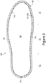
- upper 120 can include a strobel 128 or strobel sock, which is configured to extend under the wearer's foot as shown in FIGS. 4 and 5 .
- sockliner 113 extends over strobel 128 as shown in FIG. 4 and forms a surface upon which the wearer's foot rests.
- upper 120 can include one or more tensile strands 132.
- Tensile strands 132 can be yarns, cables, wires, ropes, or other strands that can extend across upper 120.
- Tensile strands 132 can be tensioned to support upper 120 and/or to distribute forces across upper 120.
- upper 120 includes one or more tensile strands 132 that extend upward along upper 120 from sole structure 110, that loop around lace-receiving elements 126, and that extend back down toward sole structure 110. Accordingly, tensile strands 132 can reinforce respective ones of the lace-receiving elements 126.
- tension in lace 125 can transfer to tensile strands 132, and tensile strands 132 can distribute loads to the upper 120 such that upper 120 can fit more securely to the wearer's foot.
- lateral side 104 and medial side 105 of upper 120 each include respective tensile strands 132.
- tensile strands 132 can extend about only some of the lace-receiving elements 126. It will be appreciated, however, that upper 120 can include any number of tensile strands 132 and that tensile strands 132 can be routed along any suitable area of upper 120 without departing from the scope of the present disclosure.
- tensile strands 132 suitable for use with upper 120 may include the tensile strands and/or tensile elements disclosed in one or more of commonly-owned U.S. Patent Application Serial Number 12/338,726 to Dua et al.
- upper 120 can be at least partially formed from a knitted component 130.
- Knitted component 130 can have any suitable shape and size. Knitted component 130 can be formed of a unitary knit construction as a one-piece element as will be discussed in detail below.
- Knitted component 130 can be configured to at least partially extend through forefoot region 101, midfoot region 102, and/or heel region 103. Knitted component 130 can also extend along lateral side 104, medial side 105, over forefoot region 101, and/or around heel region 103. In addition, knitted component 130 can at least partially define exterior surface 121 and/or interior surface 122 of upper 120.
- edges of knitted component 130 can be joined at a seam 129 to define at least some of the 3-dimensional curvature of the upper 120.
- seam 129 is located generally in the heel region 103 of upper 120; however, seam 129 can be disposed in any suitable location on upper 120.
- Knitted component 130 can also include a plurality of seams in some embodiments.
- knitted component 130 can provide upper 120 with weight savings as compared with other conventional uppers. Additionally, in some embodiments, knitted component 130 can provide desirable texture or other characteristics to upper 120. Still further, knitted component 130 can provide advantages in the manufacture of footwear 100. Other advantages provided by knitted component 130 will be explored in detail below.
- knitted component 130 can be formed to include one or more protruding areas 108.
- Protruding areas 108 can be defined on exterior surface 121 of upper 120 as illustrated in FIG. 3 .
- Protruding areas 108 can have any suitable shape and location.
- protruding areas 108 can be elongate and can extend upward from sole structure 110 on both lateral side 104 and medial side 105.
- portions of protruding areas 108 can extend longitudinally, generally between heel region 103 and forefoot region 101.
- Protruding areas 108 can be formed according to commonly-owned U.S. Patent Application Serial Number 13/944,638 to Baines et al.
- protruding areas 108 can increase surface area of upper 120 and can increase friction when footwear 100 is used, for example, to kick or trap a ball. Protruding areas 108 can also increase the wearer's ability to "feel" the ball when kicking or trapping a ball.
- upper 120 may optionally include a skin layer 140 that is attached to knitted component 130.
- a suitable configuration for skin layer 140 can be any of the embodiments of a skin layer described in commonly-owned U.S. Patent Application Serial Number 13/944,675 to Baudouin et al. , entitled “Article of Footwear Incorporating a Knitted Component", filed on July 17, 2013.
- Skin layer 140 can lay adjacent to knitted component 130 and can be secured an exterior of knitted component 130, thereby forming a majority or a relatively large portion of exterior surface 121 of upper 120.
- Various materials may be utilized to form skin layer 140, including a polymer sheet, elements of leather or synthetic leather, a woven or non-woven textile, or a metal foil.
- skin layer 140 can extend through each of forefoot region 101, midfoot region 102, and heel region 103, along both lateral side 104 and medial side 105, over forefoot region 101, and around heel region 103.
- Skin layer 140 is depicted as being absent from interior surface 122 of upper 120. In further configurations of footwear 100, skin layer 140 may be absent from other areas of upper 120 or may extend over interior surface 122. Additionally, it will be appreciated that upper 120 may not include skin layer in some embodiments and may instead be primarily constructed from knitted component 130 alone.
- a knitted workpiece may be formed that is configured to be trimmed to predetermined alternative dimensions, each associated with a differently-sized of articles of footwear. As such, manufacturing efficiency for the article of footwear can be increased. Also, assembly of the article of footwear can also be facilitated. Other advantages will also be discussed in detail below.
- a knitted workpiece 310 suitable for forming into one of a plurality of different-sized uppers for the article of footwear 100 is illustrated schematically.
- workpiece 310 can be constructed into either a first upper of a first foot size 401 or a second upper of a second foot size 402.
- the first upper 401 is illustrated as a size 8.5
- the second upper is illustrated as a size 9.
- the size 8.5 footwear can fit an anatomical foot size that is smaller than that of the size 9 footwear.
- the shoe sizes shown in FIG. 6 are merely exemplary, and other shoe sizes can be made from workpiece 310.
- workpiece 310 could be used for making an upper of any shoe size.
- workpiece 310 could be used for making three or more uppers wherein each upper fits to a different anatomical foot size.
- Workpiece 310 can be trimmed by hand or automatically to reduce the size of workpiece 310. As such, workpiece 310 can be trimmed according to the desired size of the upper 120 for the article of footwear. For example, workpiece 310 can be trimmed to a first size to form the first upper 401 of FIG. 6 , and knitted component 130 can alternatively be trimmed to a different second size to form the second upper 402 of FIG. 6 .
- FIG. 7A illustrates an exemplary method 1000 in flowchart form. It will be appreciated that the order of steps within method 1000 can vary from the order shown in FIG. 7A . Certain steps or aspects of some steps shown in FIG. 7A can be skipped or eliminated as well. Moreover, two or more steps within method 1000 can be carried out sequentially or simultaneously. Furthermore, the steps within method 1000 can be carried out manually using any suitable tools. Also, the steps within method 1000 can be carried out automatically using any suitable tool, machine, or implement.
- method 1000 can begin in step 1002, wherein a knitting process is used to form a knitted workpiece 310, such as the knitted workpiece 310 shown in FIG. 8 . Then, knitted workpiece 310 can be further processed and adjusted, for example, in step 1004, step 1006, and step 1008. These steps are also illustrated according to exemplary embodiments in FIGS. 12-15 . Then, in decision step 1012 of FIG. 7A , it can be decided whether to form an upper suitable for the first foot size 401 shown in FIG. 6 or to form an upper suitable for the second foot size 402 shown in FIG. 6 .
- Method 1000 continues in either step 1016, in which the upper for the smaller first foot size 401 is formed, or in step 1014, in which the upper for the larger second foot size 402 is formed from workpiece 310. Then, the strobel 128 and sole structure 110 are attached in steps 1018 and 1020, respectively, to finish construction of footwear 100. Each of these steps of method 1000 will be discussed in detail below.
- the method 1000 includes additional steps.
- the method 1000 can be substantially similar to the embodiments represented in FIG. 7A , except that method 1000 of FIG. 7B can include step 1010.
- skin layer 140 can be added in step 1010, which is also illustrated according to exemplary embodiments in FIG. 16 , and which will be discussed in greater detail below.
- Method 1000 can begin in step 1002.
- knitted workpiece 310 can be formed.
- knitted workpiece 310 can be formed according to the exemplary embodiments of FIG. 8 .
- Knitted workpiece 310 can be formed of a unitary knit construction.
- unitary knit construction means that the respective component is formed as a one-piece element through a knitting process. That is, the knitting process substantially forms the various features and structures of unitary knit construction without the need for significant additional manufacturing steps or processes.
- a unitary knit construction may be used to form a knitted component having structures or elements that include one or more courses of yarn or other knit material that are joined such that the structures or elements include at least one course in common (i.e., sharing a common yarn) and/or include courses that are substantially continuous between each of the structures or elements. With this arrangement, a one-piece element of unitary knit construction is provided.
- Knitted workpiece 310 can be formed from at least one yarn that is manipulated (e.g., with a knitting machine) to form a plurality of intermeshed loops that define a knit element 313 having a variety of courses and wales. Thus, adjacent areas of knit element 313 can share at least one common course or at least one common wale. That is, knit element 313 can have the structure of a knit textile. It will be appreciated that knit element 313 can be formed via weft knitting operations, warp knitting operations, flat knitting operations, circular knitting operations, or other suitable methods.
- Knit element 313 may incorporate various types and combinations of stitches and yarns.
- the yarn forming knit element 313 may have one type of stitch in one area of knit element 313 and another type of stitch in another area of knit element 313.
- areas of knit element 313 may have a plain knit structure, a mesh knit structure, or a rib knit structure, for example.
- the different types of stitches may affect the physical properties of knit element 313, including aesthetics, stretch, thickness, air permeability, and abrasion-resistance of knit element 313. That is, the different types of stitches may impart different properties to different areas of knit element 313.
- knit element 313 may have one type of yarn in one area of knit element 313 and another type of yarn in another area of knit element 313.
- knit element 313 may incorporate yarns with different deniers, materials (e.g., cotton, elastane, polyester, rayon, wool, and nylon), and degrees of twist, for example.
- the different types of yarns may affect the physical properties of knit element 313, including aesthetics, stretch, thickness, air permeability, and abrasion-resistance of knit element 313. That is, the different types of yarns may impart different properties to different areas of knit element 313.
- each area of knit element 313 may have specific properties that enhance the comfort, durability, and performance of footwear 100.
- multiple yarns with different colors may be utilized to form knit element 313. When yarns with different colors are twisted together and then knitted, knit element 313 may have a heathered appearance with multiple colors randomly distributed throughout.
- one or more of the yarns within knit element 313 may be partially formed from a thermoplastic polymer material, which softens or melts when heated and returns to a solid state when cooled. More particularly, the thermoplastic polymer material transitions from a solid state to a softened or liquid state when subjected to sufficient heat, and then the thermoplastic polymer material transitions from the softened or liquid state to the solid state when sufficiently cooled. As such, the thermoplastic polymer materials within the yarns can be used to join two objects or elements together as will be discussed in greater detail below. Knit element 313 can incorporate these so-called "fusible" yarns according to co-owned U.S. Patent No. 6,910,288, which issued on June 28, 2005 .
- method step 1002 of FIG. 2 can include knitting the exemplary knit element 313 shown in FIG. 8 .
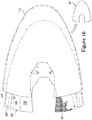
- knit element 313 is shown in plan view and is generally U-shaped. Knit element 313 can include heel region 103, midfoot region 102, forefoot region 101, lateral side 104, and medial side 105, which correspond to those same regions and sides of footwear 100 shown in FIGS. 1-4 as will become apparent.
- Knit element 313 can include an exterior surface 308 as shown in FIG. 8 , and knit element 313 can also include an opposite interior surface 309 as shown in FIG. 9 . Moreover, knit element 313 can include a generally U-shaped outer edge 312 and a generally U-shaped inner edge 314. Also, knit element 313 can include a first rear edge 316, which extends between outer edge 312 and inner edge 314. Knit element 313 can similarly include second rear edge 318, which extends between outer edge 312 and inner edge 314. It will be appreciated that the term "inboard direction” as used herein can be considered to be substantially normal to the outer edge 312 and directed inward or inboard generally toward the inner edge 314. The term “outboard direction” can be considered to be substantially normal to the outer edge 312 and directed outward or outboard generally away from the inner edge 314.
- knit element 313 of knitted workpiece 310 can be formed from a plurality of layers of knitted material.
- knit element 313 can include a first layer 322 and a second layer 324.
- first layer 322 can define exterior surface 308, and second layer 324 can define interior surface 309.
- First layer 322 and second layer 324 can overlay each other and can each span between outer edge 312, inner edge 314, first rear edge 316, and second rear edge 318. Portions of first layer 322 and second layer 324 can be attached while other portions of first layer 322 and second layer 324 can be detached from each other.
- first layer 322 and second layer 324 are detached along outer edge 312, and first layer 322 and second layer 324 are attached further inboard on the knit element 313.
- a boundary 328 can distinguish between an area where first layer 322 and second layer 324 are attached and another area where first layer 322 and second layer 324 are detached.
- boundary 328 can extend along substantially an entirety of outer edge 312 and can be spaced in an inboard direction from outer edge 312 by a distance 335.
- FIG. 10 includes a stitching diagram that is suitable for the formation of first layer 322 and second layer 324 of FIG. 9 . It will be appreciated, however, that first layer 322 and second layer 324 can be attached in any suitable area of knit element 313 and can be detached from each other in any suitable area of knit element 313.
- knit element 313 of knitted workpiece 310 can define a U-shaped central body 320, which is defined between boundary 328, first rear edge 316, inner edge 314, and second rear edge 318.
- first layer 322 and second layer 324 can be overlaid and attached to each other within central body 320.
- Knit element 313 can also define a U-shaped outer region 329, which is defined between boundary 328, first rear edge 316, outer edge 312, and second rear edge 318.
- first layer 322 and second layer 324 can be overlaid and detached within outer region 329.
- outer region 329 can have a width, which is the previously-described distance 335, between outer edge 312 and boundary 328.
- distance 335 can remain substantially constant along the longitudinal length of outer region 329 from heel region 103 to forefoot region 101.
- distance 335 can vary along the longitudinal length of outer region 329.
- outer region 329 is illustrated in FIG. 11 .
- second layer 324 can be substantially similar to the embodiments of FIG. 10 and can terminate in the outboard direction at outer edge 312.
- first layer 322 can terminate in the outboard direction short of the outer edge 312.
- outer region 329 of knit element 313 can be defined solely by second layer 324.
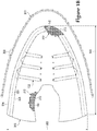
- knitted workpiece 310 can include one or more tensile strands 132 formed of unitary knit construction with knit element 313.
- tensile strands 132 can be at least partially inlaid within one or more courses and/or wales of knit element 313.
- Other areas of tensile strands 132 can extend from knit element 313 and can be exposed from knit element 313.
- knitted workpiece 310 can include two tensile strands 132, which correspond in location to those shown in the upper 120 of FIGS. 1-4 .
- separate tensile strands 132 can extend within midfoot region 102 on both lateral side 104 and medial side 105.
- knitted workpiece 310 can include any number of tensile strands 132, and tensile strands 132 can be routed along any suitable area of knit element 313.
- tensile strand 132 can include a first end 330 and a second end 332. First end 330 and second end 332 can both be disposed within outer region 329 and spaced from each other within midfoot region 102. Although tensile strand 132 can extend continuously between first end 330 and second end 332, tensile strand 132 can be considered to have a number of sections and turns.
- a first section 336 can extend from first end 330 in an inboard direction toward a rearmost lace receiving element 126 formed in knit element 313.
- Tensile strand 132 can also turn about lace receiving element 126 at a first turn 338, and a second section 340 can extend in an outboard direction toward outer region 329.
- a second turn 342 can extend from second section 340 and can extend along outer region 329.
- a third section 344 can extend in an inboard direction from second turn 342.
- a third turn 346 can turn about a respective lace receiving element 126, and a fourth section 348 can extend in an outboard direction toward the outer region 329.
- a fourth turn 350 can extend from fourth section 348 and can extend along outer region 329.
- a fifth section 352 can extend in an inboard direction
- a fifth turn 354 can turn about respective lace receiving element 126.
- a sixth section 356 can extend in an outboard direction from fifth turn 354 and can terminate at second end 332.
- first section 336, first turn 338, second section 340, third section 344, third turn 346, fourth section 348, fifth section 352, fifth turn 354, and sixth section 356 can be inlaid within the courses or wales of central body 320 of knit element 313. As such, these portions of tensile strand 132 can be substantially embedded within central body 320. In contrast, first end 330, second turn 342, fourth turn 350, and second end 332 can be disposed within outer region 329, and thus referred to as exposed portions of tensile strand 132.
- FIGS. 9 and 10 further illustrate in section view that tensile strand 132 is disposed between first layer 322 and second layer 324 within outer region 329 and is relatively exposed.
- FIG. 11 similarly illustrates that tensile strand 132 can lie upon second layer 324 within outer region 329 and can be exposed as such.
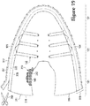
- the knitted workpiece 310 can be configured to be trimmed to a desired size.
- Workpiece 310 can be trimmed along any path.
- knit element 313 of workpiece 310 can be trimmed along one of a plurality of predetermined trim lines.
- Two exemplary trim lines are shown in FIG. 8 , namely, a first trim line 331 and a second trim line 333. Both first trim line 331 and second trim line 333 are disposed within outer region 329; therefore, outer region 329 can be referred to as a trim region as well for reasons that will become apparent.
- First trim line 331 and second trim line 333 are indicated in FIG. 8 with respective broken lines.
- First trim line 331 and second trim line 333 of the workpiece (310) according to the invention as defined in claim 10 are indicated and visually apparent on workpiece 310.
- First trim line 331 and second trim line 333 can be a representation not visually indicated on workpiece 310. It will be apparent that there can be any number of trim lines on workpiece 310 and that the trim lines can be routed along any suitable area of workpiece 310.
- first trim line 331 is U-shaped and extends continuously along outer edge 312, between first rear edge 316 and second rear edge 318, at a distance 339 from outer edge 312.
- Distance 339 can remain substantially constant along the longitudinal length of first trim line 331, or distance 339 can vary along the longitudinal length of first trim line 331.
- second trim line 333 is U-shaped and extends continuously along outer edge 312, between first rear edge 316 and second rear edge 318, at a distance 337 from outer edge 312.
- distance 337 can remain substantially constant along the longitudinal length of second trim line 333.
- distance 337 can vary along the longitudinal length of second trim line 333 so as to be larger or smaller at various portions of knitted workpiece 310.
- distance 339 can be between one to three millimeters in some embodiments.
- distance 337 can be between two and six millimeters in some embodiments.
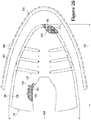
- step 1004 knitted workpiece 310 can be secured to a support surface.
- knitted workpiece 310 can be fixed to the support surface using a plurality of fasteners 362.
- fasteners 362 can include pins that extend through predetermined portions of knitted workpiece 310 and that penetrate the support surface.
- An exemplary fastener 362 is shown in perspective view in FIG. 14 being moved toward knitted workpiece 310.
- fasteners 362 can be fixed to the support surface at predetermined locations, and knitted workpiece 310 can be secured to fasteners 362 by sliding predetermined areas of workpiece 310 over fasteners 362.
- Fasteners 362 can be used to fix any suitable area of knitted workpiece 310.
- a series of fasteners 362 can be arranged along outer edge 312 and within outer region 329 of knitted workpiece 310. It will be appreciated any number of fasteners 362 can be used, and fasteners 362 can be spaced away from each other by any suitable distance.
- outer edge 312 of knitted workpiece 310 can become distorted when secured as shown in FIG. 12 . More specifically, knitted workpiece 310 can be stretched between fasteners 362, thereby causing unsecured portions to move inward and forming an uneven outer edge 312. For example, a series of indentations may form along outer edge 312 of knitted workpiece 310 between adjacent pairs of fasteners 362. These indentations can be scallops 366 having a substantially concave shape as shown in FIG. 12 , or the indentations may have another shape. Depending on the spacing of fasteners 362, the indentations or scallops 366 may have similar or varying sizes along the outer edge 312 of knitted component 310. Also, as will become apparent, the indentations or scallops 366 can be removed during subsequent trimming of the knitted workpiece 310.
- method 1000 can continue in step 1006, and tensile strands 132 can be adjusted.
- tensile strands 132 may need to be tensioned in order to remove slack within tensile strands 132.
- tensile strands 132 can be pulled to shift strands 132 relative to knit element 313.
- tensile strand 132 can be moved and adjusted relative to knit element 313 to position tensile strand 132 in a desired position and configuration.
- FIGS. 13 and 14 illustrate exemplary embodiments of step 1006.
- tensile strand 132 can be adjusted by hand. As shown in other embodiments represented in FIG. 13 , an adjustment tool 360 can be used for adjusting tensile strand 132.
- adjustment tool 360 can be a hook or other tool suitable for grasping tensile strand 132.
- adjustment tool 360 can be inserted between first layer 322 and second layer 324 of outer region 329 to grasp onto and manipulate the tensile strand 132.
- adjustment tool 360 is shown grasping fourth turn 350, but it will be appreciated that first end 330, second turn 342, or second end 332 are exposed and can be similarly grasped by tool 360.
- tool 360 can be pulled away from knitted workpiece 310.
- tensile strand 132 can be pulled in the outboard direction and/or can be otherwise shifted relative to knit element 313.
- portions of tensile strand 132 embedded within central body 320 of knit element 313 can be pulled and moved to a desired position relative to lace receiving elements 126 and/or other portions of knit element 313.
- slack within the inlaid fourth section 348 and fifth section 352 can be reduced.
- Other portions of tensile strand 132 can be similarly adjusted and moved relative to knit element 313.
- tensile strand 132 is adjusted, friction from knit element 313 can hold tensile strand 132 relative to knit element 313. Also, in some embodiments, pins or other fasteners can be used to temporarily hold tensile strands 132 in this adjusted position.
- tensile strand 132 can be disposed inboard of both first trim line 331 and second trim line 333, even after tensile strand 132 has been adjusted with tool 360.
- tensile strand 132 can be encircled collectively by first rear edge 316, inner edge 314, second rear edge 318, and second trim line 333.
- tensile strand 132 can be spaced away in an inboard direction from first trim line 331 and second trim line 333. Accordingly, when workpiece 310 is trimmed along first trim line 331 or second trim line 333, the tensile strand 132 is unlikely to be cut.
- step 1008 knitted workpiece 310 can be heated.
- a heat source 364 can be used for these purposes as shown schematically in FIG. 15 .
- heat source 364 can supply steam to knitted workpiece 310.
- heat source 364 can be configured to supply substantially dry heat to workpiece 310.
- heat source 364 can first supply steam to knitted workpiece 310, and heat source 364 can subsequently apply additional heat for drying knitted workpiece 310.
- Heat can be applied for various reasons.
- the heat can cause knitted workpiece 310 to shrink in size in a predetermined manner.
- the heat can also reduce bunching in knitted workpiece 310, can reduce slack within stitching in knit element 313, and/or flatten out knitted workpiece 310.
- knit element 313 can include fusible yarns in some embodiments. Therefore, heat from heat source 364 can cause the fusible yarns to partially melt and, upon cooling, the fusible yarns can be attached or bonded to surrounding elements or components.
- the fusible yarns can attach or bond to other surrounding fusible yarns.
- the fusible yarns can also attach or bond to respective portions of tensile strands 132 such that tensile strands 132 can be fixed relative to knit element 313.
- Step 1010 can include adding skin layer 140 to knitted workpiece 310. This is illustrated in FIG. 16 .
- skin layer 140 can be layered over and attached to exterior surface 308 of knitted workpiece 310.
- skin layer 140 is shown as covering substantially the entire knitted workpiece 310 in FIG. 16 , it will be appreciated that skin layer 140 can only partially cover knitted workpiece 310 in other embodiments.
- skin layer 140 can cover one or more indentations along outer edge 313 including one or more scallops 366.
- Skin layer 140 can also cover first trim line 331 and/or second trim line 333.
- knitted workpiece 310 and/or skinned workpiece 311 can be used to construct uppers of two different sizes. It will be appreciated that a larger shoe size will typically require a larger upper than that of a smaller shoe size. Thus, one or more edges of the knitted workpiece 310 and/or skinned workpiece 311 can be trimmed to a predetermined dimension that corresponds to the desired shoe size. For example, in the illustrated embodiments, outer edge 312 can be trimmed. However, it will be appreciated that the other edges or other areas of workpiece 310, 311 can be trimmed in some embodiments to provide workpiece 310, 311 with the desired dimensions.
- method 1000 can continue in decision step 1012. If decision step 1012 is answered affirmatively and the upper for the larger foot size 402 is to be formed, then step 1014 can follow. Step 1014 is illustrated in FIGS. 17 and 18 according to exemplary embodiments. However, if decision step 1012 is answered negatively, and the upper for the smaller foot size 401 is to be formed, then step 1016 can follow. Step 1016 is illustrated in FIGS. 19 and 20 according to exemplary embodiments.
- skinned workpiece 311 can be trimmed using a trimming tool 368 along first trim line 331.
- Trimming tool 368 can be a pair of shears as shown.
- trimming tool 368 can be a cutting die or other suitable cutting tool.
- skinned workpiece 311 can be divided into a first trimmed piece 370 and a first removed piece 372.
- first removed piece 372 can include each of the scallops 366.
- scallops 366 can be removed from first trimmed piece 370.
- first trimmed piece 370 can have a new, trimmed edge 374.
- This trimmed edge 374 can at least partially define one or more predetermined dimensions of the upper 120 for use in the larger shoe size 402 of FIG. 6 .
- trimmed edge 374 can define a predetermined first width 500 and/or first length 502 of trimmed piece 370 as shown in FIG. 18 .
- First width 500 and second width 502 dimensions can be suitable for forming the upper 120 for the size 9 shoe shown in the embodiments of FIG. 6 .
- step 1012 of FIG. 7B is answered negatively and the upper is to be formed for the smaller shoe size 401 of FIG. 6 , then skinned workpiece 311 can be trimmed along second trim line 333 as illustrated in FIG. 19 .
- skinned workpiece 311 can be divided into a second trimmed piece 376 and a second removed piece 378 as shown in FIG. 20 .
- scallops 366 can be removed, and second trimmed piece 376 can have a new, trimmed edge 380.
- trimmed edge 380 can define a predetermined second width 504 and length 506 for second trimmed piece 376.
- Second width 504 and second length 506 can be less than first width 500 and second length 502, respectively, of FIG. 18 .
- Second width 504 and second length 506 can also correspond to dimensions of upper 120 for the size 8.5 shoe shown in the embodiments of FIG. 6 .
- trimmed edge 374 of FIG. 18 and trimmed edge 380 of FIG. 20 can be bonded and secured such that trimmed edge 374 and trimmed edge 380 are unlikely to inadvertently unravel or fray.
- the fusible yarns within knit element 313 can fuse and secure trimmed edge 374 and trimmed edge 380 to prevent unraveling in some embodiments.
- skin layer 140 can bond and secure trimmed edge 374 and trimmed edge 380 to prevent unraveling.
- step 1018 strobel 128 can be attached as shown in FIG. 5 .
- strobel 128 can be attached to first trimmed edge 374 or second trimmed edge 380, whatever the case may be.
- strobel 128 can be attached via stitching, adhesives, or other fastening devices.
- portions of tensile strands 132 may be left extending freely and/or exposed relative to edge 374, 380. In these embodiments, these portions of tensile strand 132 can be secured to strobel 128, for example, via the same stitching, adhesives, or other fastening devices.
- upper 120 for the respective article of footwear 100 can be complete after step 1018.
- tags, logos, or other objects can be added to upper 120 after step 1018.
- step 1020 sole structure 110 can be attached to upper 120.
- edge 374, 380 can be disposed over, embedded, or otherwise attached to sole structure 110.
- any exposed or free ends of tensile strands 132 and respective areas of skin layer 140 can be disposed within, embedded, and fixed to sole structure 110 in step 1020.
- method 1000 can vary from the embodiment illustrated in FIG. 7B without departing from the scope of the present disclosure.
- steps shown in FIG. 7B can be omitted, added, combined with other steps, substituted with alternate steps, or otherwise varied.
- FIG. 7A an alternate embodiment of method 1000 is illustrated in FIG. 7A .
- method 1000 can be substantially similar to that shown in FIG. 7B ; however, step 1010 has been omitted.
- optional skin layer 140 is not added to knitted workpiece 310 in this embodiment of method 1000. Instead, knitted workpiece 310 is heated in step 1008, and then knitted workpiece 310 is trimmed in step 1014 or step 1016 as discussed above with reference to FIGS. 17-20 .
- method 1000 and the articles constructed using method 1000 can increase manufacturing efficiency. For example, fewer tools, devices, parts, and other implements may be needed since the same tools, devices, parts, and implements can be used to form uppers 120 of different sizes. Also, bottlenecks in forming footwear 100 caused by the knitting process can be reduced since the same knitted workpiece 310 can be used to form two different-sized uppers 120. Additionally, by removing the indentations, scallops 366 or other irregularities causing an uneven edge from knitted workpiece 310 and/or skinned workpiece 311, attaching strobel 128 can be facilitated since the mating edges are more likely to butt up directly together.
Landscapes
- Engineering & Computer Science (AREA)
- Textile Engineering (AREA)
- Chemical & Material Sciences (AREA)
- Materials Engineering (AREA)
- Footwear And Its Accessory, Manufacturing Method And Apparatuses (AREA)
- Knitting Of Fabric (AREA)
- Composite Materials (AREA)
- Treatment Of Fiber Materials (AREA)
Description
- Conventional articles of footwear generally include two primary elements: an upper and a sole structure. The upper is secured to the sole structure and forms a void within the footwear for comfortably and securely receiving a foot. The sole structure is secured to a lower surface of the upper so as to be positioned between the upper and the ground.
- In some articles of athletic footwear, for example, the sole structure may include a midsole and an outsole. The midsole may be formed from a polymer foam material that attenuates ground reaction forces to lessen stresses upon the foot and leg during walking, running, and other ambulatory activities. The outsole is secured to a lower surface of the midsole and forms a ground-engaging portion of the sole structure that is formed from a durable and wear-resistant material. The sole structure may also include a sockliner positioned within the void and proximal a lower surface of the foot to enhance footwear comfort.
- The upper can extend over the instep and toe areas of the foot, along the medial and lateral sides of the foot, and around the heel area of the foot. In some articles of footwear, such as basketball footwear and boots, the upper may extend upward and around the ankle to provide support or protection for the ankle. Access to the void on the interior of the upper is generally provided by an ankle opening in a heel region of the footwear. A lacing system is often incorporated into the upper to adjust the fit of the upper, thereby permitting entry and removal of the foot from the void within the upper. The lacing system also permits the wearer to modify certain dimensions of the upper, particularly girth, to accommodate feet with varying dimensions. In addition, the upper may include a footwear, and the upper may incorporate a heel counter to limit movement of the heel.
- Various materials are conventionally utilized in manufacturing the upper. The upper of athletic footwear, for example, may be formed from multiple material elements. The materials may be selected based upon various properties, including stretch-resistance, wear-resistance, flexibility, air-permeability, compressibility, and moisture-wicking, for example. Specifically, the upper may be formed of leather, synthetic leather, or a rubber material. The upper may be formed from numerous material elements that each imparts different properties to the upper.
-
WO 9003744 A1 - The invention is set out in the appended set of claims. A method of forming an article of footwear according to the invention is defined in
Claim 1. - Furthermore, a workpiece configured for forming one of a first upper for a first article of footwear and a second upper for a second article of footwear according to the invention is defined in
Claim 10. The first upper and the first article of footwear are configured to fit to a first foot size, and the second upper and the second article of footwear are configured to fit to a second foot size. The workpiece includes a knitted component having a knit element and a tensile strand that are formed of unitary knit construction. The knitted component is configured to at least partially form one of the first upper and the second upper. The knit element defines a body and a trim region, and the trim region defines an outer edge of the knit element. The tensile strand includes at least one inlaid portion that is inlaid within the knit element, and the tensile strand also includes an exposed portion that is exposed from the knit element and that is disposed adjacent the outer edge. The exposed portion is spaced from the outer edge in an inboard direction on the knit element. The exposed portion is configured to be manipulated to thereby move and adjust the inlaid portion relative to the knit element. Also, the trim region is trimmable along one of a first trim line to form the first upper and a second trim line to form the second upper, wherein the first trim line and the second trim line are indicated and visually apparent on the workpiece. - Embodiments of the inventions are defined in the dependent claims.
- The present disclosure can be better understood with reference to the following drawings and description. The components in the figures are not necessarily to scale, emphasis instead being placed upon illustrating the principles of the present disclosure. Moreover, in the figures, like reference numerals designate corresponding parts throughout the different views.
-
FIG. 1 is a lateral side view of an article of footwear according to exemplary embodiments of the present disclosure; -
FIG. 2 is a medial side view of the article of footwear ofFIG. 1 ; -
FIG. 3 is a top view of the article of footwear ofFIG. 1 ; -
FIG. 4 is a section view of the article of footwear taken along the line 4-4 ofFIG. 3 ; -
FIG. 5 is a bottom view of an upper of the article of footwear ofFIG. 1 with a strobel; -
FIG. 6 is a schematic view of a workpiece including a knitted component that can be formed into one of a plurality of different-sized uppers for the article of footwear ofFIG. 1 ; -
FIG. 7A is a flowchart of a method of manufacturing the article of footwear ofFIG. 1 according to exemplary embodiments; -
FIG. 7B is a flowchart of the method of manufacturing the article of footwear ofFIG. 1 according to additional exemplary embodiments; -
FIG. 8 is a plan view of a workpiece for the article of footwear ofFIG. 1 according to exemplary embodiments of the present disclosure; -
FIG. 9 is a section view of the workpiece taken along the line 9-9 ofFIG. 8 ; -
FIG. 10 is a schematic section view of the workpiece ofFIG. 8 showing a stitching pattern for the workpiece according to exemplary embodiments of the present disclosure; -
FIG. 11 is a schematic section view of the workpiece showing a stitching pattern according to additional exemplary embodiments of the present disclosure; -
FIG. 12 is a plan view of the workpiece ofFIG. 8 shown with fastening elements for securing the workpiece to a support surface; -
FIGS. 13 and14 are plan views of the workpiece ofFIG. 12 and a tool for adjusting a tensile strand of the workpiece; -
FIG. 15 is a plan view of the workpiece ofFIG. 14 shown in the process of being heated; -
FIG. 16 is a schematic plan view of the workpiece ofFIG. 15 and a skin layer in the process of being attached to the workpiece; -
FIGS. 17 and18 are schematic plan views of the workpiece ofFIG. 16 being trimmed along a first trim line to form the upper for the article of footwear of a first foot size; and -
FIGS. 19 and20 are schematic plan views of the workpiece ofFIG. 16 being trimmed along a second trim line to form the upper for the article of footwear of a second foot size. - The following discussion and accompanying figures disclose an article of footwear having an upper that includes a knitted component and a method for manufacturing such an upper. In some embodiments, the upper can be formed from a knitted workpiece that is trimmed down to a predetermined size to fit a particular anatomical foot size. This can increase manufacturing efficiency and provide additional advantages as will be explained in greater detail below.
- The article of footwear is disclosed as having a general configuration suitable for walking or running. Concepts associated with the footwear, including the upper, may also be applied to a variety of other athletic footwear types, including soccer shoes, baseball shoes, basketball shoes, cross-training shoes, cycling shoes, football shoes, sprinting shoes, tennis shoes, and hiking boots, for example. The concepts may also be applied to footwear types that are generally considered to be non-athletic, including dress shoes, loafers, sandals, and work boots. The concepts disclosed herein apply, therefore, to a wide variety of footwear types.
- An article of
footwear 100 is depicted inFIGS. 1-4 as including asole structure 110 and an upper 120. Whereassole structure 110 is located under and supports a foot of a wearer, upper 120 provides a comfortable and secure covering for the foot. As such, the foot may be located within a void in upper 120 to effectively secure the foot withinfootwear 100 or otherwise unite the foot andfootwear 100. Moreover,sole structure 110 is secured to a lower area of upper 120 and extends between the foot and the ground to attenuate ground reaction forces (i.e., cushion the foot), provide traction, enhance stability, and influence the motions of the foot, for example. - For reference purposes,
footwear 100 may be divided into three general regions: aforefoot region 101, amidfoot region 102, and aheel region 103.Forefoot region 101 generally encompasses portions offootwear 100 corresponding with forward portions of the foot, including the toes and joints connecting the metatarsals with the phalanges.Midfoot region 102 generally encompasses portions offootwear 100 corresponding with middle portions of the foot, including an arch area.Heel region 103 generally encompasses portions offootwear 100 corresponding with rear portions of the foot, including the heel and calcaneus bone.Footwear 100 also includes alateral side 104 and amedial side 105, which extend throughforefoot region 101,midfoot region 102, andheel region 103, and which correspond with opposite sides offootwear 100. More particularly,lateral side 104 corresponds with an outside area of the foot (i.e. the surface that faces away from the other foot), andmedial side 105 corresponds with an inside area of the foot (i.e., the surface that faces toward the other foot).Forefoot region 101,midfoot region 102,heel region 103,lateral side 104, andmedial side 105 are not intended to demarcate precise areas offootwear 100. Rather,forefoot region 101,midfoot region 102,heel region 103,lateral side 104, andmedial side 105 are intended to represent general areas offootwear 100 to aid in the following discussion. In addition tofootwear 100,forefoot region 101,midfoot region 102,heel region 103,lateral side 104, andmedial side 105 may also be applied tosole structure 110, upper 120, and individual elements thereof. -
Sole structure 110 can include amidsole 111, anoutsole 112, and asockliner 113, each of which is shown in the section view ofFIG. 4 .Midsole 111 can be secured to a lower surface of upper 120 and may be formed from a compressible polymer foam element (e.g., a polyurethane or ethylvinylacetate foam) that attenuates ground reaction forces (i.e., provides cushioning) when compressed between the foot and the ground during walking, running, or other ambulatory activities. In further configurations,midsole 111 may incorporate plates, moderators, fluid-filled chambers, lasting elements, or motion control members that further attenuate forces, enhance stability, or influence the motions of the foot, ormidsole 111 may be primarily formed from a fluid-filled chamber.Outsole 112 can be secured to a lower surface ofmidsole 111 and may be formed from a wear-resistant rubber material that is textured to impart traction.Sockliner 113 can be located within the void in upper 120 and positioned to extend under a lower surface of the foot to enhance the comfort offootwear 100. Although this configuration forsole structure 110 provides an example of a sole structure that may be used in connection with upper 120, a variety of other conventional or nonconventional configurations forsole structure 110 may also be utilized. For example,outsole 112 can additionally include cleats or spikes that are configured to penetrate into the ground in some embodiments. Accordingly, the features ofsole structure 110 or any sole structure utilized with upper 120 may vary from the illustrated embodiments without departing from the scope of the present disclosure. -
Upper 120 includes anexterior surface 121 and an oppositeinterior surface 122. Whereasexterior surface 121 faces outward and away fromfootwear 100,interior surface 122 faces inward and can define a majority or a relatively large portion of the void withinfootwear 100 for receiving the foot. The void can be shaped to accommodate the wearer's foot. When the foot is located within the void, therefore, upper 120 can extend along a lateral side of the foot, along a medial side of the foot, over the foot, around the heel, and under the foot. Moreover,interior surface 122 may lie against the foot or a sock covering the foot. - As shown in
FIGS. 1 and2 , upper 120 can also include acollar 123 that is primarily located inheel region 103 and forms anopening 106 that provides the foot with access to the void within upper 120. More particularly, the foot may be inserted into upper 120 throughopening 106 formed bycollar 123, and the foot may be withdrawn from upper 120 throughopening 106 formed bycollar 123. As shown inFIGS. 1 and2 ,collar 123 can be of a so-called "high top" or "high rise" collar for extending up and over the wearers ankle. In additional embodiments,collar 123 can be of a so-called "low rise" collar that merely extends around the wearer's ankle. - A
throat area 127 can be included forward ofcollar 123 and can extend longitudinally towardforefoot region 101 and betweenlateral side 104 andmedial side 105. As shown inFIG. 3 ,throat area 127 can be integrally attached toforefoot region 101,lateral side 104, andmedial side 105. In other embodiments,throat area 127 can include a tongue that is detached fromlateral side 104 andmedial side 105. As such, the tongue can be moveably received within an opening withinthroat area 127 betweenlateral side 104 andmedial side 105. - In some embodiments, a
closure element 107 can also be included that is used to selectively secure upper 120 to the wearer's foot.Closure element 107 can be of any suitable type, such as alace 125 as shown in the illustrated embodiments. In other embodiments,closure element 107 may also include one or more buckles, straps, loop-and-pile tape, or other suitable implements for securing upper 120 to a wearer's foot. - As shown in the illustrated embodiments,
lace 125 can engage various lace-receivingelements 126. Although lace-receivingelements 126 are depicted inFIGS. 1-4 as apertures in upper 120, and withlace 125 passing through the apertures, lace-receivingelements 126 may be loops, eyelets, hooks, D-rings, or other suitable lace-receiving element. - As shown in
FIG. 3 ,lace 125 can follow a zigzagging path between respective lace-receivingelements 126. Moreover,lace 125 can repeatedly-pass across and between opposite sides ofthroat area 127. When usingfootwear 100,lace 125 permits the wearer to selectively modify dimensions of upper 120 to accommodate the proportions of the foot. More particularly,lace 125 may be manipulated in a conventional manner to permit the wearer to (a) tighten upper 120 around the foot and (b) loosen upper 120 to facilitate insertion and withdrawal throughopening 106 formed bycollar 123. - Also, upper 120 may extend under the wearer's foot. For example, upper 120 can include a
strobel 128 or strobel sock, which is configured to extend under the wearer's foot as shown inFIGS. 4 and5 . In this configuration,sockliner 113 extends overstrobel 128 as shown inFIG. 4 and forms a surface upon which the wearer's foot rests. - In some embodiments, upper 120 can include one or more
tensile strands 132.Tensile strands 132 can be yarns, cables, wires, ropes, or other strands that can extend across upper 120.Tensile strands 132 can be tensioned to support upper 120 and/or to distribute forces across upper 120. For example, in the illustrated embodiment, upper 120 includes one or moretensile strands 132 that extend upward along upper 120 fromsole structure 110, that loop around lace-receivingelements 126, and that extend back down towardsole structure 110. Accordingly,tensile strands 132 can reinforce respective ones of the lace-receivingelements 126. Also, tension inlace 125 can transfer totensile strands 132, andtensile strands 132 can distribute loads to the upper 120 such that upper 120 can fit more securely to the wearer's foot. - In the illustrated embodiments,
lateral side 104 andmedial side 105 of upper 120 each include respectivetensile strands 132. Also, as shown,tensile strands 132 can extend about only some of the lace-receivingelements 126. It will be appreciated, however, that upper 120 can include any number oftensile strands 132 and thattensile strands 132 can be routed along any suitable area of upper 120 without departing from the scope of the present disclosure. Moreover,tensile strands 132 suitable for use with upper 120 may include the tensile strands and/or tensile elements disclosed in one or more of commonly-ownedU.S. Patent Application Serial Number 12/338,726 to Dua et al.U.S. Patent Application Publication Number 2010/0154256 on June 24, 2010 , andU.S. Patent , entitled "Article Of Footwear Incorporating A Knitted Component", filed on March 15, 2011 and published asApplication Serial Number 13/048,514 to Huffa et al.U.S. Patent Application Publication Number 2012/0233882 on September 20, 2012 . - Many conventional footwear uppers are formed from multiple material elements (e.g., polymer foam, polymer sheets, leather, synthetic leather) that are joined together through stitching or bonding, for example. However, in various embodiments discussed herein, upper 120 can be at least partially formed from a
knitted component 130.Knitted component 130 can have any suitable shape and size.Knitted component 130 can be formed of a unitary knit construction as a one-piece element as will be discussed in detail below. -
Knitted component 130 can be configured to at least partially extend throughforefoot region 101,midfoot region 102, and/orheel region 103.Knitted component 130 can also extend alonglateral side 104,medial side 105, overforefoot region 101, and/or aroundheel region 103. In addition, knittedcomponent 130 can at least partially defineexterior surface 121 and/orinterior surface 122 of upper 120. - As will be discussed in detail below, and as shown in
FIG. 3 , edges ofknitted component 130 can be joined at aseam 129 to define at least some of the 3-dimensional curvature of the upper 120. As shown inFIG. 3 ,seam 129 is located generally in theheel region 103 of upper 120; however,seam 129 can be disposed in any suitable location on upper 120.Knitted component 130 can also include a plurality of seams in some embodiments. - As will be discussed, knitted
component 130 can provide upper 120 with weight savings as compared with other conventional uppers. Additionally, in some embodiments, knittedcomponent 130 can provide desirable texture or other characteristics to upper 120. Still further, knittedcomponent 130 can provide advantages in the manufacture offootwear 100. Other advantages provided byknitted component 130 will be explored in detail below. - In some embodiments, knitted
component 130 can be formed to include one or moreprotruding areas 108.Protruding areas 108 can be defined onexterior surface 121 of upper 120 as illustrated inFIG. 3 .Protruding areas 108 can have any suitable shape and location. For example, protrudingareas 108 can be elongate and can extend upward fromsole structure 110 on bothlateral side 104 andmedial side 105. Moreover, portions of protrudingareas 108 can extend longitudinally, generally betweenheel region 103 andforefoot region 101.Protruding areas 108 can be formed according to commonly-ownedU.S. Patent Application Serial Number 13/944,638 to Baines et al.areas 108 can increase surface area of upper 120 and can increase friction whenfootwear 100 is used, for example, to kick or trap a ball.Protruding areas 108 can also increase the wearer's ability to "feel" the ball when kicking or trapping a ball. - Additionally, in some embodiments, upper 120 may optionally include a
skin layer 140 that is attached toknitted component 130. A suitable configuration forskin layer 140 can be any of the embodiments of a skin layer described in commonly-ownedU.S. Patent Application Serial Number 13/944,675 to Baudouin et al. -
Skin layer 140 can lay adjacent toknitted component 130 and can be secured an exterior ofknitted component 130, thereby forming a majority or a relatively large portion ofexterior surface 121 of upper 120. Various materials may be utilized to formskin layer 140, including a polymer sheet, elements of leather or synthetic leather, a woven or non-woven textile, or a metal foil. As withknitted component 130,skin layer 140 can extend through each offorefoot region 101,midfoot region 102, andheel region 103, along bothlateral side 104 andmedial side 105, overforefoot region 101, and aroundheel region 103.Skin layer 140 is depicted as being absent frominterior surface 122 of upper 120. In further configurations offootwear 100,skin layer 140 may be absent from other areas of upper 120 or may extend overinterior surface 122. Additionally, it will be appreciated that upper 120 may not include skin layer in some embodiments and may instead be primarily constructed from knittedcomponent 130 alone. - In some embodiments, a knitted workpiece may be formed that is configured to be trimmed to predetermined alternative dimensions, each associated with a differently-sized of articles of footwear. As such, manufacturing efficiency for the article of footwear can be increased. Also, assembly of the article of footwear can also be facilitated. Other advantages will also be discussed in detail below.
- Referring now to
FIG. 6 , aknitted workpiece 310 suitable for forming into one of a plurality of different-sized uppers for the article offootwear 100 is illustrated schematically. As will be explained,workpiece 310 can be constructed into either a first upper of afirst foot size 401 or a second upper of asecond foot size 402. InFIG. 6 , the first upper 401 is illustrated as a size 8.5, and the second upper is illustrated as asize 9. The size 8.5 footwear can fit an anatomical foot size that is smaller than that of thesize 9 footwear. It will be appreciated that the shoe sizes shown inFIG. 6 are merely exemplary, and other shoe sizes can be made fromworkpiece 310. Also,workpiece 310 could be used for making an upper of any shoe size. Additionally, it will be appreciated thatworkpiece 310 could be used for making three or more uppers wherein each upper fits to a different anatomical foot size. -
Workpiece 310 can be trimmed by hand or automatically to reduce the size ofworkpiece 310. As such,workpiece 310 can be trimmed according to the desired size of the upper 120 for the article of footwear. For example,workpiece 310 can be trimmed to a first size to form the first upper 401 ofFIG. 6 , andknitted component 130 can alternatively be trimmed to a different second size to form the second upper 402 ofFIG. 6 . - Various methods, machines, and tools can be used for forming, trimming, and otherwise adjusting
workpiece 310 and for forming article offootwear 100 fromworkpiece 310. For example,FIG. 7A illustrates anexemplary method 1000 in flowchart form. It will be appreciated that the order of steps withinmethod 1000 can vary from the order shown inFIG. 7A . Certain steps or aspects of some steps shown inFIG. 7A can be skipped or eliminated as well. Moreover, two or more steps withinmethod 1000 can be carried out sequentially or simultaneously. Furthermore, the steps withinmethod 1000 can be carried out manually using any suitable tools. Also, the steps withinmethod 1000 can be carried out automatically using any suitable tool, machine, or implement. - Generally, in the embodiments represented in
FIG. 7A ,method 1000 can begin instep 1002, wherein a knitting process is used to form aknitted workpiece 310, such as theknitted workpiece 310 shown inFIG. 8 . Then, knitted workpiece 310 can be further processed and adjusted, for example, instep 1004,step 1006, andstep 1008. These steps are also illustrated according to exemplary embodiments inFIGS. 12-15 . Then, indecision step 1012 ofFIG. 7A , it can be decided whether to form an upper suitable for thefirst foot size 401 shown inFIG. 6 or to form an upper suitable for thesecond foot size 402 shown inFIG. 6 .Method 1000 continues in eitherstep 1016, in which the upper for the smallerfirst foot size 401 is formed, or instep 1014, in which the upper for the largersecond foot size 402 is formed fromworkpiece 310. Then, thestrobel 128 andsole structure 110 are attached insteps footwear 100. Each of these steps ofmethod 1000 will be discussed in detail below. - In additional embodiments shown in
FIG. 7B , themethod 1000 includes additional steps. For example, themethod 1000 can be substantially similar to the embodiments represented inFIG. 7A , except thatmethod 1000 ofFIG. 7B can includestep 1010. Specifically,skin layer 140 can be added instep 1010, which is also illustrated according to exemplary embodiments inFIG. 16 , and which will be discussed in greater detail below. - Embodiments of
method 1000 illustrated inFIG. 7A will now be discussed in greater detail.Method 1000 can begin instep 1002. Instep 1002, knittedworkpiece 310 can be formed. For example, knittedworkpiece 310 can be formed according to the exemplary embodiments ofFIG. 8 . - Knitted
workpiece 310 can be formed of a unitary knit construction. As used herein, the term "unitary knit construction" means that the respective component is formed as a one-piece element through a knitting process. That is, the knitting process substantially forms the various features and structures of unitary knit construction without the need for significant additional manufacturing steps or processes. A unitary knit construction may be used to form a knitted component having structures or elements that include one or more courses of yarn or other knit material that are joined such that the structures or elements include at least one course in common (i.e., sharing a common yarn) and/or include courses that are substantially continuous between each of the structures or elements. With this arrangement, a one-piece element of unitary knit construction is provided. Examples of various configurations of knitted components and methods for forming knittedworkpiece 310 with unitary knit construction are disclosed inU.S. Patent Number 6,931,762 to Dua ;U.S. Patent Number 7,347,011 to Dua, et al. ;U.S. Patent Application Publication 2008/0110048 to Dua, et al. ;U.S. Patent Application Publication 2010/0154256 to Dua ; andU.S. Patent Application Publication 20120233882 to Huffa, et al. . - Knitted
workpiece 310 can be formed from at least one yarn that is manipulated (e.g., with a knitting machine) to form a plurality of intermeshed loops that define aknit element 313 having a variety of courses and wales. Thus, adjacent areas ofknit element 313 can share at least one common course or at least one common wale. That is, knitelement 313 can have the structure of a knit textile. It will be appreciated thatknit element 313 can be formed via weft knitting operations, warp knitting operations, flat knitting operations, circular knitting operations, or other suitable methods. -
Knit element 313 may incorporate various types and combinations of stitches and yarns. With regard to stitches, the yarn formingknit element 313 may have one type of stitch in one area ofknit element 313 and another type of stitch in another area ofknit element 313. Depending upon the types and combinations of stitches utilized, areas ofknit element 313 may have a plain knit structure, a mesh knit structure, or a rib knit structure, for example. The different types of stitches may affect the physical properties ofknit element 313, including aesthetics, stretch, thickness, air permeability, and abrasion-resistance ofknit element 313. That is, the different types of stitches may impart different properties to different areas ofknit element 313. With regard to yarns,knit element 313 may have one type of yarn in one area ofknit element 313 and another type of yarn in another area ofknit element 313. Depending upon various design criteria,knit element 313 may incorporate yarns with different deniers, materials (e.g., cotton, elastane, polyester, rayon, wool, and nylon), and degrees of twist, for example. The different types of yarns may affect the physical properties ofknit element 313, including aesthetics, stretch, thickness, air permeability, and abrasion-resistance ofknit element 313. That is, the different types of yarns may impart different properties to different areas ofknit element 313. By combining various types and combinations of stitches and yarns, each area ofknit element 313 may have specific properties that enhance the comfort, durability, and performance offootwear 100. In some configurations, multiple yarns with different colors may be utilized to formknit element 313. When yarns with different colors are twisted together and then knitted,knit element 313 may have a heathered appearance with multiple colors randomly distributed throughout. - Also, one or more of the yarns within
knit element 313 may be partially formed from a thermoplastic polymer material, which softens or melts when heated and returns to a solid state when cooled. More particularly, the thermoplastic polymer material transitions from a solid state to a softened or liquid state when subjected to sufficient heat, and then the thermoplastic polymer material transitions from the softened or liquid state to the solid state when sufficiently cooled. As such, the thermoplastic polymer materials within the yarns can be used to join two objects or elements together as will be discussed in greater detail below.Knit element 313 can incorporate these so-called "fusible" yarns according to co-ownedU.S. Patent No. 6,910,288, which issued on June 28, 2005 . - As stated,
method step 1002 ofFIG. 2 can include knitting theexemplary knit element 313 shown inFIG. 8 . As shown, knitelement 313 is shown in plan view and is generally U-shaped.Knit element 313 can includeheel region 103,midfoot region 102,forefoot region 101,lateral side 104, andmedial side 105, which correspond to those same regions and sides offootwear 100 shown inFIGS. 1-4 as will become apparent. -
Knit element 313 can include anexterior surface 308 as shown inFIG. 8 , andknit element 313 can also include an oppositeinterior surface 309 as shown inFIG. 9 . Moreover,knit element 313 can include a generally U-shapedouter edge 312 and a generally U-shapedinner edge 314. Also,knit element 313 can include a firstrear edge 316, which extends betweenouter edge 312 andinner edge 314.Knit element 313 can similarly include secondrear edge 318, which extends betweenouter edge 312 andinner edge 314. It will be appreciated that the term "inboard direction" as used herein can be considered to be substantially normal to theouter edge 312 and directed inward or inboard generally toward theinner edge 314. The term "outboard direction" can be considered to be substantially normal to theouter edge 312 and directed outward or outboard generally away from theinner edge 314. - As shown in
FIG. 9 ,knit element 313 of knittedworkpiece 310 can be formed from a plurality of layers of knitted material. For example,knit element 313 can include afirst layer 322 and asecond layer 324. In this embodiment,first layer 322 can defineexterior surface 308, andsecond layer 324 can defineinterior surface 309.First layer 322 andsecond layer 324 can overlay each other and can each span betweenouter edge 312,inner edge 314, firstrear edge 316, and secondrear edge 318. Portions offirst layer 322 andsecond layer 324 can be attached while other portions offirst layer 322 andsecond layer 324 can be detached from each other. In the embodiments ofFIG. 9 , for example,first layer 322 andsecond layer 324 are detached alongouter edge 312, andfirst layer 322 andsecond layer 324 are attached further inboard on theknit element 313. Thus, in some embodiments, aboundary 328 can distinguish between an area wherefirst layer 322 andsecond layer 324 are attached and another area wherefirst layer 322 andsecond layer 324 are detached. Also, as shown inFIG. 8 ,boundary 328 can extend along substantially an entirety ofouter edge 312 and can be spaced in an inboard direction fromouter edge 312 by adistance 335.FIG. 10 includes a stitching diagram that is suitable for the formation offirst layer 322 andsecond layer 324 ofFIG. 9 . It will be appreciated, however, thatfirst layer 322 andsecond layer 324 can be attached in any suitable area ofknit element 313 and can be detached from each other in any suitable area ofknit element 313. - Accordingly,
knit element 313 of knittedworkpiece 310 can define a U-shapedcentral body 320, which is defined betweenboundary 328, firstrear edge 316,inner edge 314, and secondrear edge 318. Stated differently,first layer 322 andsecond layer 324 can be overlaid and attached to each other withincentral body 320.Knit element 313 can also define a U-shapedouter region 329, which is defined betweenboundary 328, firstrear edge 316,outer edge 312, and secondrear edge 318. Thus,first layer 322 andsecond layer 324 can be overlaid and detached withinouter region 329. It will be apparent, thus, thatouter region 329 can have a width, which is the previously-describeddistance 335, betweenouter edge 312 andboundary 328. In some embodiments,distance 335 can remain substantially constant along the longitudinal length ofouter region 329 fromheel region 103 to forefootregion 101. In additional embodiments,distance 335 can vary along the longitudinal length ofouter region 329. - An alternative embodiment of
outer region 329 is illustrated inFIG. 11 . As shown,second layer 324 can be substantially similar to the embodiments ofFIG. 10 and can terminate in the outboard direction atouter edge 312. However,first layer 322 can terminate in the outboard direction short of theouter edge 312. Accordingly, whilecentral body 320 is defined by attachedfirst layer 322 andsecond layer 324,outer region 329 ofknit element 313 can be defined solely bysecond layer 324. - As shown in the embodiment of
FIG. 8 , knittedworkpiece 310 can include one or moretensile strands 132 formed of unitary knit construction withknit element 313. For example,tensile strands 132 can be at least partially inlaid within one or more courses and/or wales ofknit element 313. Other areas oftensile strands 132 can extend fromknit element 313 and can be exposed fromknit element 313. - As shown in the embodiment of
FIG. 8 , knittedworkpiece 310 can include twotensile strands 132, which correspond in location to those shown in the upper 120 ofFIGS. 1-4 . Thus, separatetensile strands 132 can extend withinmidfoot region 102 on bothlateral side 104 andmedial side 105. It will be appreciated, however, that knittedworkpiece 310 can include any number oftensile strands 132, andtensile strands 132 can be routed along any suitable area ofknit element 313. - For purposes of clarity, one of the
tensile strands 132 in the embodiment ofFIG. 8 will be discussed. It will be appreciated that bothtensile strands 132 can have similar and corresponding features even thoughtensile strands 132 are routed on opposite sides ofworkpiece 310. As shown,tensile strand 132 can include afirst end 330 and asecond end 332.First end 330 andsecond end 332 can both be disposed withinouter region 329 and spaced from each other withinmidfoot region 102. Althoughtensile strand 132 can extend continuously betweenfirst end 330 andsecond end 332,tensile strand 132 can be considered to have a number of sections and turns. For example, afirst section 336 can extend fromfirst end 330 in an inboard direction toward a rearmostlace receiving element 126 formed inknit element 313.Tensile strand 132 can also turn aboutlace receiving element 126 at afirst turn 338, and asecond section 340 can extend in an outboard direction towardouter region 329. Asecond turn 342 can extend fromsecond section 340 and can extend alongouter region 329. Also, a third section 344 can extend in an inboard direction fromsecond turn 342. Moreover, athird turn 346 can turn about a respectivelace receiving element 126, and afourth section 348 can extend in an outboard direction toward theouter region 329. Next, afourth turn 350 can extend fromfourth section 348 and can extend alongouter region 329. Additionally, afifth section 352 can extend in an inboard direction, and afifth turn 354 can turn about respectivelace receiving element 126. Also, asixth section 356 can extend in an outboard direction fromfifth turn 354 and can terminate atsecond end 332. - It will be appreciated that
first section 336,first turn 338,second section 340, third section 344,third turn 346,fourth section 348,fifth section 352,fifth turn 354, andsixth section 356 can be inlaid within the courses or wales ofcentral body 320 ofknit element 313. As such, these portions oftensile strand 132 can be substantially embedded withincentral body 320. In contrast,first end 330,second turn 342,fourth turn 350, andsecond end 332 can be disposed withinouter region 329, and thus referred to as exposed portions oftensile strand 132.FIGS. 9 and 10 further illustrate in section view thattensile strand 132 is disposed betweenfirst layer 322 andsecond layer 324 withinouter region 329 and is relatively exposed.FIG. 11 similarly illustrates thattensile strand 132 can lie uponsecond layer 324 withinouter region 329 and can be exposed as such. - As mentioned above and as will be discussed in detail, the
knitted workpiece 310 can be configured to be trimmed to a desired size.Workpiece 310 can be trimmed along any path. For example, as will be discussed in detail,knit element 313 ofworkpiece 310 can be trimmed along one of a plurality of predetermined trim lines. Two exemplary trim lines are shown inFIG. 8 , namely, a firsttrim line 331 and a secondtrim line 333. Both firsttrim line 331 and secondtrim line 333 are disposed withinouter region 329; therefore,outer region 329 can be referred to as a trim region as well for reasons that will become apparent. - First
trim line 331 and secondtrim line 333 are indicated inFIG. 8 with respective broken lines. Firsttrim line 331 and secondtrim line 333 of the workpiece (310) according to the invention as defined inclaim 10 are indicated and visually apparent onworkpiece 310. Firsttrim line 331 and secondtrim line 333 can be a representation not visually indicated onworkpiece 310. It will be apparent that there can be any number of trim lines onworkpiece 310 and that the trim lines can be routed along any suitable area ofworkpiece 310. - In the exemplary embodiments of
FIG. 8 , firsttrim line 331 is U-shaped and extends continuously alongouter edge 312, between firstrear edge 316 and secondrear edge 318, at adistance 339 fromouter edge 312. Distance 339 can remain substantially constant along the longitudinal length of firsttrim line 331, ordistance 339 can vary along the longitudinal length of firsttrim line 331. Also, secondtrim line 333 is U-shaped and extends continuously alongouter edge 312, between firstrear edge 316 and secondrear edge 318, at adistance 337 fromouter edge 312. In this embodiment,distance 337 can remain substantially constant along the longitudinal length of secondtrim line 333. In other embodiments,distance 337 can vary along the longitudinal length of secondtrim line 333 so as to be larger or smaller at various portions of knittedworkpiece 310. In some embodiments,distance 339 can be between one to three millimeters in some embodiments. Also,distance 337 can be between two and six millimeters in some embodiments. - Referring back to
method 1000 shown inFIG. 7A , once knitted workpiece 310 is formed instep 1002,method 1000 can continue instep 1004. Instep 1004, knittedworkpiece 310 can be secured to a support surface. For example, as shown inFIG. 12 , knittedworkpiece 310 can be fixed to the support surface using a plurality offasteners 362. In some embodiments,fasteners 362 can include pins that extend through predetermined portions of knittedworkpiece 310 and that penetrate the support surface. Anexemplary fastener 362 is shown in perspective view inFIG. 14 being moved toward knittedworkpiece 310. In additional embodiments,fasteners 362 can be fixed to the support surface at predetermined locations, and knittedworkpiece 310 can be secured tofasteners 362 by sliding predetermined areas ofworkpiece 310 overfasteners 362. -
Fasteners 362 can be used to fix any suitable area of knittedworkpiece 310. For example, as shown inFIG. 14 , a series offasteners 362 can be arranged alongouter edge 312 and withinouter region 329 of knittedworkpiece 310. It will be appreciated any number offasteners 362 can be used, andfasteners 362 can be spaced away from each other by any suitable distance. - Also,
outer edge 312 of knittedworkpiece 310 can become distorted when secured as shown inFIG. 12 . More specifically, knittedworkpiece 310 can be stretched betweenfasteners 362, thereby causing unsecured portions to move inward and forming an unevenouter edge 312. For example, a series of indentations may form alongouter edge 312 of knittedworkpiece 310 between adjacent pairs offasteners 362. These indentations can bescallops 366 having a substantially concave shape as shown inFIG. 12 , or the indentations may have another shape. Depending on the spacing offasteners 362, the indentations orscallops 366 may have similar or varying sizes along theouter edge 312 ofknitted component 310. Also, as will become apparent, the indentations orscallops 366 can be removed during subsequent trimming of theknitted workpiece 310. - As shown in
FIG. 7A ,method 1000 can continue instep 1006, andtensile strands 132 can be adjusted. For example,tensile strands 132 may need to be tensioned in order to remove slack withintensile strands 132. Also,tensile strands 132 can be pulled to shiftstrands 132 relative to knitelement 313. Stated differently,tensile strand 132 can be moved and adjusted relative to knitelement 313 to positiontensile strand 132 in a desired position and configuration.FIGS. 13 and14 illustrate exemplary embodiments ofstep 1006. - In some embodiments,
tensile strand 132 can be adjusted by hand. As shown in other embodiments represented inFIG. 13 , anadjustment tool 360 can be used for adjustingtensile strand 132. For example,adjustment tool 360 can be a hook or other tool suitable for graspingtensile strand 132. - As shown in
FIGS. 13 and14 ,adjustment tool 360 can be inserted betweenfirst layer 322 andsecond layer 324 ofouter region 329 to grasp onto and manipulate thetensile strand 132. In the illustrated embodiments,adjustment tool 360 is shown graspingfourth turn 350, but it will be appreciated thatfirst end 330,second turn 342, orsecond end 332 are exposed and can be similarly grasped bytool 360. - Then, as shown in
FIG. 14 ,tool 360 can be pulled away from knittedworkpiece 310. As a result,tensile strand 132 can be pulled in the outboard direction and/or can be otherwise shifted relative to knitelement 313. Stated differently, portions oftensile strand 132 embedded withincentral body 320 ofknit element 313 can be pulled and moved to a desired position relative to lace receivingelements 126 and/or other portions ofknit element 313. For example, in the embodiments ofFIG. 13 , by pulling and otherwise manipulatingfourth turn 350, slack within the inlaidfourth section 348 andfifth section 352 can be reduced. Other portions oftensile strand 132 can be similarly adjusted and moved relative to knitelement 313. Oncetensile strand 132 is adjusted, friction fromknit element 313 can holdtensile strand 132 relative to knitelement 313. Also, in some embodiments, pins or other fasteners can be used to temporarily holdtensile strands 132 in this adjusted position. - As shown in the illustrated embodiments of
FIG. 13 ,tensile strand 132 can be disposed inboard of both firsttrim line 331 and secondtrim line 333, even aftertensile strand 132 has been adjusted withtool 360. Stated differently, in the plan view ofFIG. 13 ,tensile strand 132 can be encircled collectively by firstrear edge 316,inner edge 314, secondrear edge 318, and secondtrim line 333. Thus,tensile strand 132 can be spaced away in an inboard direction from firsttrim line 331 and secondtrim line 333. Accordingly, whenworkpiece 310 is trimmed along firsttrim line 331 or secondtrim line 333, thetensile strand 132 is unlikely to be cut. - Subsequently, as shown in
FIG. 7A ,method 1000 can continue instep 1008. Instep 1008, knittedworkpiece 310 can be heated. Aheat source 364 can be used for these purposes as shown schematically inFIG. 15 . In some embodiments,heat source 364 can supply steam to knittedworkpiece 310. In other embodiments,heat source 364 can be configured to supply substantially dry heat toworkpiece 310. In still additional embodiments,heat source 364 can first supply steam to knittedworkpiece 310, andheat source 364 can subsequently apply additional heat for drying knittedworkpiece 310. - Heat can be applied for various reasons. In some embodiments, the heat can cause knitted
workpiece 310 to shrink in size in a predetermined manner. The heat can also reduce bunching in knittedworkpiece 310, can reduce slack within stitching inknit element 313, and/or flatten outknitted workpiece 310. Also, as stated above,knit element 313 can include fusible yarns in some embodiments. Therefore, heat fromheat source 364 can cause the fusible yarns to partially melt and, upon cooling, the fusible yarns can be attached or bonded to surrounding elements or components. For example, the fusible yarns can attach or bond to other surrounding fusible yarns. The fusible yarns can also attach or bond to respective portions oftensile strands 132 such thattensile strands 132 can be fixed relative to knitelement 313. - Next,
method 1000 can continue instep 1012 as shown inFIG. 7A and as described below. Alternatively, as shown inFIG. 7B ,method 1000 can continue instep 1010.Step 1010 can include addingskin layer 140 to knittedworkpiece 310. This is illustrated inFIG. 16 . As shown,skin layer 140 can be layered over and attached toexterior surface 308 of knittedworkpiece 310. Althoughskin layer 140 is shown as covering substantially the entireknitted workpiece 310 inFIG. 16 , it will be appreciated thatskin layer 140 can only partially cover knittedworkpiece 310 in other embodiments. Also, in some embodiments,skin layer 140 can cover one or more indentations alongouter edge 313 including one ormore scallops 366.Skin layer 140 can also cover firsttrim line 331 and/or secondtrim line 333. Onceskin layer 140 is attached, knittedworkpiece 310 can be converted to a "skinned workpiece 311" as shown inFIG. 16 . - As mentioned above, and as shown in
FIG. 6 , knittedworkpiece 310 and/orskinned workpiece 311 can be used to construct uppers of two different sizes. It will be appreciated that a larger shoe size will typically require a larger upper than that of a smaller shoe size. Thus, one or more edges of theknitted workpiece 310 and/orskinned workpiece 311 can be trimmed to a predetermined dimension that corresponds to the desired shoe size. For example, in the illustrated embodiments,outer edge 312 can be trimmed. However, it will be appreciated that the other edges or other areas ofworkpiece workpiece - Thus, as shown in
FIG. 7B ,method 1000 can continue indecision step 1012. Ifdecision step 1012 is answered affirmatively and the upper for thelarger foot size 402 is to be formed, then step 1014 can follow.Step 1014 is illustrated inFIGS. 17 and18 according to exemplary embodiments. However, ifdecision step 1012 is answered negatively, and the upper for thesmaller foot size 401 is to be formed, then step 1016 can follow.Step 1016 is illustrated inFIGS. 19 and20 according to exemplary embodiments. - Assuming that the larger upper for the
larger foot size 402 is to be formed,skinned workpiece 311 can be trimmed using atrimming tool 368 along firsttrim line 331. Trimmingtool 368 can be a pair of shears as shown. In additional embodiments, trimmingtool 368 can be a cutting die or other suitable cutting tool. Once fully trimmed,skinned workpiece 311 can be divided into a first trimmedpiece 370 and a firstremoved piece 372. As shown in the illustrated embodiments, first removedpiece 372 can include each of thescallops 366. Thus,scallops 366 can be removed from first trimmedpiece 370. Also, as a result of this trimming, first trimmedpiece 370 can have a new, trimmededge 374. This trimmededge 374 can at least partially define one or more predetermined dimensions of the upper 120 for use in thelarger shoe size 402 ofFIG. 6 . Specifically, trimmededge 374 can define a predeterminedfirst width 500 and/orfirst length 502 of trimmedpiece 370 as shown inFIG. 18 .First width 500 andsecond width 502 dimensions can be suitable for forming the upper 120 for thesize 9 shoe shown in the embodiments ofFIG. 6 . - In contrast, if
step 1012 ofFIG. 7B is answered negatively and the upper is to be formed for thesmaller shoe size 401 ofFIG. 6 , then skinnedworkpiece 311 can be trimmed along secondtrim line 333 as illustrated inFIG. 19 . As a result,skinned workpiece 311 can be divided into a second trimmedpiece 376 and a secondremoved piece 378 as shown inFIG. 20 . Thus,scallops 366 can be removed, and second trimmedpiece 376 can have a new, trimmededge 380. Also, trimmededge 380 can define a predeterminedsecond width 504 and length 506 for second trimmedpiece 376.Second width 504 and second length 506 can be less thanfirst width 500 andsecond length 502, respectively, ofFIG. 18 .Second width 504 and second length 506 can also correspond to dimensions of upper 120 for the size 8.5 shoe shown in the embodiments ofFIG. 6 . - Additionally, it will be appreciated that trimmed
edge 374 ofFIG. 18 and trimmededge 380 ofFIG. 20 can be bonded and secured such that trimmededge 374 and trimmededge 380 are unlikely to inadvertently unravel or fray. For example, the fusible yarns withinknit element 313 can fuse and secure trimmededge 374 and trimmededge 380 to prevent unraveling in some embodiments. Also, in some embodiments,skin layer 140 can bond and secure trimmededge 374 and trimmededge 380 to prevent unraveling. - Referring back to
FIG. 7B ,method 1000 can continue instep 1018. Instep 1018,strobel 128 can be attached as shown inFIG. 5 . Specifically,strobel 128 can be attached to first trimmededge 374 or second trimmededge 380, whatever the case may be. Moreover,strobel 128 can be attached via stitching, adhesives, or other fastening devices. Additionally, in some embodiments, portions oftensile strands 132 may be left extending freely and/or exposed relative to edge 374, 380. In these embodiments, these portions oftensile strand 132 can be secured tostrobel 128, for example, via the same stitching, adhesives, or other fastening devices. It will be appreciated that, in some embodiments, upper 120 for the respective article offootwear 100 can be complete afterstep 1018. In additional embodiments, tags, logos, or other objects can be added to upper 120 afterstep 1018. - Finally, as shown in
FIG. 7B ,method 1000 can conclude instep 1020. Instep 1020,sole structure 110 can be attached to upper 120. As shown inFIG. 4 ,edge sole structure 110. Likewise, any exposed or free ends oftensile strands 132 and respective areas ofskin layer 140 can be disposed within, embedded, and fixed tosole structure 110 instep 1020. - As stated above,
method 1000 can vary from the embodiment illustrated inFIG. 7B without departing from the scope of the present disclosure. For example, steps shown inFIG. 7B can be omitted, added, combined with other steps, substituted with alternate steps, or otherwise varied. For example, an alternate embodiment ofmethod 1000 is illustrated inFIG. 7A . As shown,method 1000 can be substantially similar to that shown inFIG. 7B ; however,step 1010 has been omitted. Thus,optional skin layer 140 is not added to knittedworkpiece 310 in this embodiment ofmethod 1000. Instead, knittedworkpiece 310 is heated instep 1008, and then knittedworkpiece 310 is trimmed instep 1014 orstep 1016 as discussed above with reference toFIGS. 17-20 . - Accordingly,
method 1000 and the articles constructed usingmethod 1000 can increase manufacturing efficiency. For example, fewer tools, devices, parts, and other implements may be needed since the same tools, devices, parts, and implements can be used to formuppers 120 of different sizes. Also, bottlenecks in formingfootwear 100 caused by the knitting process can be reduced since the sameknitted workpiece 310 can be used to form two different-sized uppers 120. Additionally, by removing the indentations,scallops 366 or other irregularities causing an uneven edge from knittedworkpiece 310 and/orskinned workpiece 311, attachingstrobel 128 can be facilitated since the mating edges are more likely to butt up directly together. - While various embodiments of the present disclosure have been described, the description is intended to be exemplary rather than limiting, and it will be apparent to those of ordinary skill in the art that many more embodiments and implementations are possible that are within the scope of the present invention defined by the attached claims.
Claims (15)
- A method (1000) of forming an article of footwear (100) that is configured to fit one of a first foot size and a second foot size, the first foot size being larger than the second foot size, the method comprising:knitting a knitted workpiece (310), the knitted workpiece (310) configured to at least partially form an upper (120) of the article of footwear (100), the knitted workpiece (310) having a body (320) and a trim region, the trim region defining at least a portion of an outer edge (312) of the knitted workpiece (310), a first dimension of the knitted workpiece (310) defined at least partly by the outer edge;heating the knitted workpiece (310);trimming the knitted workpiece (310) within the trim region after heating the knitted workpiece (310) to remove a piece from the knitted workpiece (310) and to reduce the first dimension to a second dimension; andforming the upper (120) from the trimmed knitted workpiece, wherein the method (1000) is characterized by selecting whether to form the article of footwear (100) to fit the first foot size (401) or the second foot size (402),wherein trimming the knitted workpiece (310) includes trimming the knitted workpiece along a first trim line (331) when selecting to form the article of footwear to fit the first foot size, andwherein trimming the knitted workpiece includes trimming the knitted workpiece along a second trim line (333) when selecting to form the article of footwear to fit the second foot size,the second trim line being spaced from the first trim line in an inboard direction on the knitted workpiece.
- The method (1000) of claim 1, further comprising attaching a skin layer to the knitted workpiece (310).
- The method (1000) of claim 2, wherein attaching the skin layer occurs after heating the knitted workpiece (310) and before trimming the knitted workpiece (310).
- The method (1000) of claim 1, wherein knitting the knitted workpiece (310) includes knitting the knitted workpiece (310) with at least one fusible strand.
- The method (1000) of claim 1, wherein knitting the knitted workpiece (310) includes knitting the knitted workpiece to include a knit element (313) and a tensile strand (132), the tensile strand including at least one inlaid portion that is inlaid within the knit element (313), the tensile strand (132) also including an exposed portion that is exposed from the knit element (313), wherein the exposed portion is spaced from the outer edge in an inboard direction on the knitted workpiece (310), and further comprising pulling on the exposed portion to move and adjust the at least one inlaid portion relative to the knit element (313).
- The method (1000) of claim 5, wherein the at least one inlaid portion includes a first inlaid portion and a second inlaid portion, and wherein the exposed portion extends continuously between the first inlaid portion and the second inlaid portion.
- The method (1000) of claim 5, wherein knitting the knitted workpiece (310) includes forming the outer edge (312) with a first layer (332) and a second layer (334), the first layer and the second layer overlaying each other and connected in the body (320), the first layer and the second layer overlaying each other and disconnected in the trim region, and wherein knitting the knitted workpiece (310) includes disposing the exposed portion of the tensile strand (132) between the first layer and the second layer in the trim region.
- The method (1000) of claim 5, wherein knitting the knitted workpiece (310) includes knitting the knitted workpiece (310) with a first layer (332) and a second layer, the first layer and the second layer overlaying each other and connected in the body (320), the first layer extending further in an outboard direction on the knitted component than the second layer to define the trim region and the outer edge (312), and wherein knitting the knitted workpiece (310) includes disposing the exposed portion of the tensile strand (132) on the first layer within the trim region.
- The method (1000) of claim 1, further comprising fixing a first area of the knitted workpiece (310) to a support surface and fixing a second area of the knitted workpiece (310) to the support surface before heating the knitted workpiece, the first area and the second area being spaced from each other along the outer edge (312), wherein an indentation is formed in the outer edge between the first area and the second area, and wherein trimming the knitted workpiece includes removing the indentation from the knitted workpiece.
- A workpiece (310) configured for forming one of a first upper for a first article of footwear and a second upper for a second article of footwear, the first upper and the first article of footwear configured to fit to a first foot size, and the second upper and the second article of footwear configured to fit to a second foot size, the workpiece comprising:a knitted component having a knit element (313) and a tensile strand (132) that are formed of unitary knit construction, the knitted component configured to at least partially form one of the first upper and the second upper, the knit element (313) defining a body (320) and a trim region, the trim region defining an outer edge (312) of the knit element (313), the tensile strand (132) including at least one inlaid portion that is inlaid within the knit element (313), the tensile strand (132) also including an exposed portion that is exposed from the knit element (313) and that is disposed adjacent the outer edge (312), the exposed portion being configured for pulling to thereby move and adjust the at least one inlaid portion relative to the knit element, wherein the exposed portion is spaced from the outer edge in an inboard direction on the knit element, andwherein the trim region is trimmable along one of a first trim line (331) to form the first upper (401) and a second trim (333) line to form the second upper (402), wherein the first trim line (331) and the second trim line (333) are indicated and visually apparent on workpiece (310).
- The workpiece (310) of claim 10, wherein the knitted component includes a first inlaid portion and a second inlaid portion of the tensile strand (132), and wherein the exposed portion extends continuously between the first inlaid portion and the second inlaid portion.
- The workpiece (310) of claim 10, wherein the knit element (313) includes a first layer (332) and a second layer (334) formed of unitary knit construction, the first layer and the second layer overlaying each other and connected in the body (320), the first layer (332) and the second layer overlaying each other and disconnected in the trim region, and wherein the exposed portion of the tensile strand (132) is disposed between the first layer (332) and the second layer in the trim region.
- The workpiece (310) of claim 10, wherein the knit element (313) includes a first layer (332) and a second layer (334) formed of unitary knit construction, the first layer and the second layer (334) overlaying each other and connected in the body (320), the first layer extending further in an outboard direction on the knitted component than the second layer (334) to define the trim region and the outer edge (312), and wherein the exposed portion of the tensile strand (132) is disposed on the first layer within the trim region.
- The workpiece (310) of claim 10, further comprising a skin layer that is attached to the knitted component, the skin layer lying over at least one of the first trim line (331) and the second trim line (333).
- The workpiece (310) of claim 10, further comprising a sale structure that is attached to one of the first upper (401) and the second upper (402), the sale structure further attached to the exposed portion of the tensile strand (132).
Priority Applications (1)
| Application Number | Priority Date | Filing Date | Title |
|---|---|---|---|
| EP20151131.8A EP3673758B1 (en) | 2013-09-05 | 2014-06-23 | Method of forming an article of footwear incorporating a knitted upper with tensile strand |
Applications Claiming Priority (2)
| Application Number | Priority Date | Filing Date | Title |
|---|---|---|---|
| US14/018,787 US10092058B2 (en) | 2013-09-05 | 2013-09-05 | Method of forming an article of footwear incorporating a knitted upper with tensile strand |
| PCT/US2014/043597 WO2015034568A1 (en) | 2013-09-05 | 2014-06-23 | Method of forming an article of footwear incorporating a knitted upper with tensile strand |
Related Child Applications (1)
| Application Number | Title | Priority Date | Filing Date |
|---|---|---|---|
| EP20151131.8A Division EP3673758B1 (en) | 2013-09-05 | 2014-06-23 | Method of forming an article of footwear incorporating a knitted upper with tensile strand |
Publications (2)
| Publication Number | Publication Date |
|---|---|
| EP3041379A1 EP3041379A1 (en) | 2016-07-13 |
| EP3041379B1 true EP3041379B1 (en) | 2020-02-05 |
Family
ID=51211869
Family Applications (2)
| Application Number | Title | Priority Date | Filing Date |
|---|---|---|---|
| EP20151131.8A Active EP3673758B1 (en) | 2013-09-05 | 2014-06-23 | Method of forming an article of footwear incorporating a knitted upper with tensile strand |
| EP14741724.0A Active EP3041379B1 (en) | 2013-09-05 | 2014-06-23 | Method of forming an article of footwear incorporating a knitted upper with tensile strand |
Family Applications Before (1)
| Application Number | Title | Priority Date | Filing Date |
|---|---|---|---|
| EP20151131.8A Active EP3673758B1 (en) | 2013-09-05 | 2014-06-23 | Method of forming an article of footwear incorporating a knitted upper with tensile strand |
Country Status (11)
| Country | Link |
|---|---|
| US (1) | US10092058B2 (en) |
| EP (2) | EP3673758B1 (en) |
| JP (1) | JP6504171B2 (en) |
| KR (1) | KR102174123B1 (en) |
| CN (2) | CN104414022B (en) |
| AR (1) | AR097574A1 (en) |
| BR (1) | BR112016005031B1 (en) |
| HK (1) | HK1207943A1 (en) |
| MX (1) | MX364867B (en) |
| TW (2) | TWI573535B (en) |
| WO (1) | WO2015034568A1 (en) |
Families Citing this family (19)
| Publication number | Priority date | Publication date | Assignee | Title |
|---|---|---|---|---|
| US8490299B2 (en) | 2008-12-18 | 2013-07-23 | Nike, Inc. | Article of footwear having an upper incorporating a knitted component |
| US8701232B1 (en) | 2013-09-05 | 2014-04-22 | Nike, Inc. | Method of forming an article of footwear incorporating a trimmed knitted upper |
| US10092058B2 (en) * | 2013-09-05 | 2018-10-09 | Nike, Inc. | Method of forming an article of footwear incorporating a knitted upper with tensile strand |
| US10130142B2 (en) * | 2015-04-14 | 2018-11-20 | Nike, Inc. | Article of footwear with knitted component having biased inter-toe member |
| TWI727198B (en) * | 2015-05-29 | 2021-05-11 | 荷蘭商耐克創新有限合夥公司 | Article of footwear flat pattern and method of manufacturing article of footwear |
| DE102015220865A1 (en) * | 2015-10-26 | 2017-04-27 | Adidas Ag | Shoeupper |
| US20170311681A1 (en) * | 2016-04-29 | 2017-11-02 | Aknit International Ltd. | Shoe body-forming piece and manufacturing method thereof |
| DE102016215263A1 (en) | 2016-08-16 | 2018-02-22 | Adidas Ag | Shoe top for a shoe |
| US10844526B2 (en) * | 2016-10-23 | 2020-11-24 | Nike, Inc. | Upper including a knitted component having structures with apertures extending from a surface |
| US11224261B2 (en) * | 2017-02-10 | 2022-01-18 | Nike, Inc. | Knitted article with at least one scallop element and methods of manufacture |
| EP3599925B1 (en) * | 2017-03-24 | 2022-08-03 | NIKE Innovate C.V. | Last and method of lasting an upper |
| US10485302B2 (en) * | 2017-07-07 | 2019-11-26 | Reebok International Limited | Method of making an upper |
| US10874172B2 (en) | 2018-04-04 | 2020-12-29 | Adidas Ag | Articles of footwear with uppers comprising a wound component and methods of making the same |
| CN112512364B (en) * | 2018-07-20 | 2022-06-14 | 耐克创新有限合伙公司 | Article of footwear incorporating a knitted component and receiving a strap component |
| US20210177095A1 (en) * | 2019-12-17 | 2021-06-17 | Under Armour, Inc. | Article of Footwear with Braided Upper |
| DE102019220470B4 (en) * | 2019-12-20 | 2023-05-17 | Adidas Ag | Knitted shoe upper with integral eyelets |
| US11602196B2 (en) | 2020-07-13 | 2023-03-14 | Adidas Ag | Articles of footwear comprising a wound component and methods of making the same |
| WO2024054583A1 (en) | 2022-09-09 | 2024-03-14 | MillerKnoll, Inc. | Seating structure having a knitted suspension material |
| US20240081465A1 (en) * | 2022-09-14 | 2024-03-14 | Lululemon Athletica Canada Inc. | Upper for Article of Footwear Incorporating a Knitted Butterfly Workpiece |
Family Cites Families (200)
| Publication number | Priority date | Publication date | Assignee | Title |
|---|---|---|---|---|
| US601192A (en) | 1898-03-22 | Tongue for boots or shoes | ||
| US1215198A (en) | 1916-09-21 | 1917-02-06 | Joseph Rothstein | Cushion instep-raiser. |
| US1597934A (en) | 1922-10-10 | 1926-08-31 | Edwin B Stimpson | Stocking |
| US1774620A (en) * | 1924-01-25 | 1930-09-02 | United Shoe Machinery Corp | Preparation of shoe uppers |
| US1616080A (en) | 1925-11-23 | 1927-02-01 | Frandor Mfg Co Inc | Fabric with patterns printed thereon |
| US1902780A (en) | 1930-04-11 | 1933-03-21 | Holden Knitting Co | Knitted lining for rubber footwear and method of making same |
| US1910251A (en) | 1931-12-09 | 1933-05-23 | Reliable Knitting Works | Knitted foot covering and method of making the same |
| US1888172A (en) | 1932-06-06 | 1932-11-15 | Reliable Knitting Works | Knitted footwear and method of making the same |
| US2001293A (en) | 1934-02-10 | 1935-05-14 | Wilson Wallace | Knitted stocking foot protector |
| US2047724A (en) * | 1934-07-12 | 1936-07-14 | Louis G Zuckerman | Knitted article and method of making same |
| US2049175A (en) * | 1935-07-06 | 1936-07-28 | Richard J Regan | Method of making applique shoes |
| US2147197A (en) | 1936-11-25 | 1939-02-14 | Hood Rubber Co Inc | Article of footwear |
| US2330199A (en) | 1939-05-22 | 1943-09-28 | Basch Olive Holmes | Knitted article |
| GB538865A (en) | 1939-11-18 | 1941-08-20 | Harold Edmund Brew | Improvements relating to knitted fabrics and manufactured knitted articles |
| US2314098A (en) | 1941-04-26 | 1943-03-16 | Mary C Mcdonald | Method of making shoes |
| US2343390A (en) | 1941-11-26 | 1944-03-07 | United Shoe Machinery Corp | Method of stiffening shoes |
| US2400692A (en) | 1943-03-24 | 1946-05-21 | Theotiste N Herbert | Foot covering |
| US2440393A (en) | 1944-08-18 | 1948-04-27 | Frank W Clark | Process of making last-fitting fabric uppers |
| US2465911A (en) | 1945-12-21 | 1949-03-29 | Paul K Morgan | Waterproof shoe protector with severable sections |
| US2467237A (en) | 1946-03-18 | 1949-04-12 | Mishawaka Rubber | Method of making boots from knitted tubular stock |
| US2569764A (en) | 1946-07-25 | 1951-10-02 | Boyd Welsh Inc | Initially soft stiffenable material |
| US2608078A (en) | 1950-01-04 | 1952-08-26 | Munsingwear Inc | Foundation garment and element therefor |
| US2586045A (en) * | 1950-06-23 | 1952-02-19 | Hoza John | Sock-type footwear |
| US2641004A (en) | 1950-12-26 | 1953-06-09 | David V Whiting | Method for producing knitted shoe uppers of shrinkable yarn |
| US2675631A (en) * | 1951-02-13 | 1954-04-20 | Doughty John Carr | Footwear article of the slipper-sock type |
| DE870963C (en) | 1951-03-13 | 1953-03-19 | Georg Hofer | Strap for boots, especially for ski boots |
| US2702463A (en) * | 1951-05-03 | 1955-02-22 | Roosevelt Mills Inc | Thermal-insulation fabric and method of making the same |
| DE1084173B (en) | 1954-09-18 | 1960-06-23 | Walter Geissler | Shoe upper |
| US2994322A (en) | 1959-01-12 | 1961-08-01 | Charles C Cullen | Protective supporter |
| US3115693A (en) * | 1959-05-11 | 1963-12-31 | Du Pont | Process of making a knitted fabric |
| CH512209A (en) * | 1962-11-18 | 1971-09-15 | Duo Internat Inc | Method of manufacturing the upper of a shoe and device for its implementation |
| US3329983A (en) * | 1965-08-20 | 1967-07-11 | United Shoe Machinery Corp | Methods of manufacturing shoe uppers |
| GB1223285A (en) | 1967-08-29 | 1971-02-24 | Onitsuka Co | Improvements in shoes |
| US3523304A (en) | 1968-01-24 | 1970-08-11 | Montgomery Ward & Co | Precut garment construction |
| DE6944404U (en) | 1969-11-14 | 1970-02-19 | Justus Rieker Co Dr | INNER SHOE FOR BOOTS, IN PARTICULAR SKI BOOTS MADE OF PLASTIC |
| US3698027A (en) | 1970-11-10 | 1972-10-17 | Semperit Ag | Manufacture of articles of footwear |
| US3704474A (en) | 1971-10-21 | 1972-12-05 | Compo Ind Inc | Method of string-lasting |
| US3766566A (en) | 1971-11-01 | 1973-10-23 | S Tadokoro | Hem forming construction of garments, particularly trousers and skirts |
| US3778856A (en) | 1971-11-05 | 1973-12-18 | Salient Eng Ltd | String lasting |
| NL7301642A (en) | 1972-02-07 | 1973-08-09 | ||
| NL7304678A (en) | 1973-04-04 | 1974-10-08 | Non woven stitched fabric - including thermoplastic fibres fused to increase mech resistance | |
| US4211806A (en) | 1973-09-19 | 1980-07-08 | Milliken Research Corporation | Treated fabric structure |
| US3952427A (en) | 1974-05-09 | 1976-04-27 | Von Den Benken Elisabeth | Insole for footwear |
| US4031586A (en) | 1974-05-09 | 1977-06-28 | Von Den Benken Elisabeth | Insole for footwear |
| IT1015280B (en) | 1974-06-21 | 1977-05-10 | Toja E | MACHINE FOR THE ASSEMBLY OF TO UPPER DIRECTLY ON THE ASSEMBLY SHAPES |
| US4125001A (en) * | 1975-12-15 | 1978-11-14 | Austen Bryars Of London, Inc. | Multi-gauge knit fabric with inlay |
| US4027402A (en) | 1976-04-02 | 1977-06-07 | Liu Hsing Ching | Novel educational toy |
| US4232458A (en) | 1978-03-13 | 1980-11-11 | Wheelabrator Corp. Of Canada | Shoe |
| GB1603487A (en) | 1978-03-30 | 1981-11-25 | Inmont Corp | Leather like materials |
| SE408161B (en) | 1978-04-05 | 1979-05-21 | Tetra Pak Int | DEVICE FOR STERILIZING A PACKAGING MATERIAL PATH |
| US4258480A (en) | 1978-08-04 | 1981-03-31 | Famolare, Inc. | Running shoe |
| US4255949A (en) | 1979-08-16 | 1981-03-17 | Thorneburg James L | Athletic socks with integrally knit arch cushion |
| USRE30638E (en) * | 1979-11-14 | 1981-06-09 | Austen Bryars Of London, Inc. | Multi-gauge knit fabric with fleece inlay yarn |
| US4317292A (en) | 1979-12-04 | 1982-03-02 | Florence Melton | Slipper sock and method of manufacture |
| US4387516A (en) | 1980-12-22 | 1983-06-14 | L & A, Inc. | Universal insole |
| US4373361A (en) | 1981-04-13 | 1983-02-15 | Thorneburg James L | Ski sock with integrally knit thickened fabric areas |
| IT8121560V0 (en) | 1981-04-23 | 1981-04-23 | Nuova Zarine Costruzione Macch | FOOTWEAR WITH UPPER ZONALLY COVERED BY SYNTHETIC MATERIAL INJECTED STABLY JOINED TO THE CANVAS. |
| US4465448A (en) | 1982-03-19 | 1984-08-14 | Norwich Shoe Co., Inc. | Apparatus for making shoes |
| US5095720A (en) | 1982-07-14 | 1992-03-17 | Annedeen Hosiery Mill, Inc. | Circular weft knitting machine |
| JPS59162041A (en) | 1983-03-04 | 1984-09-12 | アキレス株式会社 | Manufacture of sheet-shaped article |
| US4562834A (en) | 1983-12-12 | 1986-01-07 | Norman Bates | Waterproof limb covering |
| JPS6325004U (en) | 1986-07-31 | 1988-02-18 | ||
| HUT60607A (en) | 1986-08-19 | 1992-10-28 | Horst Forschner | Method for producing wearing apparels carrying out by the user and set for producing such wearing apparels |
| US4756098A (en) | 1987-01-21 | 1988-07-12 | Gencorp Inc. | Athletic shoe |
| US4737396A (en) | 1987-02-04 | 1988-04-12 | Crown Textile Company | Composite fusible interlining fabric |
| US4813158A (en) | 1987-02-06 | 1989-03-21 | Reebok International Ltd. | Athletic shoe with mesh reinforcement |
| US4750339A (en) | 1987-02-17 | 1988-06-14 | Golden Needles Knitting & Glove Co., Inc. | Edge binding for fabric articles |
| DE3705908A1 (en) | 1987-02-24 | 1988-09-01 | Arova Mammut Ag | PADDED BELT |
| US5152025A (en) | 1988-07-29 | 1992-10-06 | Sergio Hirmas | Method for manufacturing open-heeled shoes |
| JPH04505107A (en) | 1988-10-03 | 1992-09-10 | ジェン ジェン ホールディングズ,インコーポレイテッド | heat embossed shoes |
| JPH0390665A (en) | 1989-01-06 | 1991-04-16 | Ikenaga:Kk | Pattern making control device of filling knitting machine |
| US4967491A (en) | 1989-05-04 | 1990-11-06 | Howard Plotkin | Disposable, collapsable overshoe |
| DE59002580D1 (en) | 1989-06-03 | 1993-10-07 | Dassler Puma Sportschuh | SHOE WITH A FASTENING SHAFT MATERIAL WITH A LOCKING DEVICE. |
| DE68926789T2 (en) | 1989-10-18 | 1996-11-14 | Toray Industries | METHOD FOR PRODUCING FABRIC WITH OVERLAPING LAMPS |
| US5192601A (en) | 1991-03-25 | 1993-03-09 | Dicey Fabrics, Incorporated | Dimensionally stabilized, fusibly bonded multilayered fabric and process for producing same |
| WO1992022223A1 (en) * | 1991-06-17 | 1992-12-23 | Puma Aktiengesellschaft Rudolf Dassler Sport | Method of producing a shaped shoe part from a strip of fabric, and a shaped shoe part produced by this method |
| DE69218565T2 (en) | 1991-12-11 | 1997-08-07 | Nitto Boseki Co Ltd | Meltable adhesive yarn and process for its manufacture |
| JPH06113905A (en) | 1992-02-21 | 1994-04-26 | Daiyu Shoji:Kk | Instep covering material for shoes |
| US5365677A (en) | 1992-06-30 | 1994-11-22 | Dalhgren Raymond E | Footwear for facilitating the removal and dissipation of perspiration from the foot of a wearer |
| US5623840A (en) | 1992-07-08 | 1997-04-29 | Tecnit-Technische Textilien Und Systeme Gmbh | Process for production of weave-knit material |
| US5319807A (en) | 1993-05-25 | 1994-06-14 | Brier Daniel L | Moisture-management sock and shoe for creating a moisture managing environment for the feet |
| CH689665A5 (en) | 1993-09-07 | 1999-08-13 | Lange Int Sa | Shoe portion other than the sole, in particular slipper tongue inside ski boot. |
| US5371957A (en) | 1993-12-14 | 1994-12-13 | Adidas America, Inc. | Athletic shoe |
| US5461884A (en) | 1994-01-19 | 1995-10-31 | Guilford Mills, Inc. | Warp-knitted textile fabric shoe liner and method of producing same |
| MX9603677A (en) | 1994-02-28 | 1997-06-28 | Adam H Oreck | Shoe having lace tubes. |
| JPH08109553A (en) | 1994-10-04 | 1996-04-30 | Toho Seni Kk | Foundation cloth for three-layer sheet, its production and three-layer sheet for automobile seat, shoes, bag, pouch, etc., produced by using the three-layer foundation cloth |
| DE19506037A1 (en) | 1995-02-22 | 1996-08-29 | Hoechst Trevira Gmbh & Co Kg | Deformable, heat-stabilizable textile pile goods |
| US20050147787A1 (en) | 2000-08-08 | 2005-07-07 | Bailey Larry M. | Carpet construction and carpet backings for same |
| BR9602748A (en) | 1995-06-13 | 1998-04-22 | Faytex Corp | Footwear frame |
| EP0758693B1 (en) | 1995-08-11 | 2001-10-24 | BUCK, Alfred | Semi-finished product for composite material |
| US5678325A (en) | 1996-01-11 | 1997-10-21 | Columbia Footwear Corporation | Clog type shoe with a drawstring |
| US5735145A (en) | 1996-05-20 | 1998-04-07 | Monarch Knitting Machinery Corporation | Weft knit wicking fabric and method of making same |
| DE29616943U1 (en) | 1996-09-28 | 1996-11-21 | Recytex-Textilaufbereitung GmbH & Co. KG, 41751 Viersen | Textile fabrics |
| US5729918A (en) | 1996-10-08 | 1998-03-24 | Nike, Inc. | Method of lasting an article of footwear and footwear made thereby |
| US5765296A (en) | 1997-01-31 | 1998-06-16 | Nine West Group, Inc. | Exercise shoe having fit adaptive upper |
| DE19728848A1 (en) | 1997-07-05 | 1999-01-07 | Kunert Werke Gmbh | Stocking, etc. |
| JP3044370B2 (en) | 1997-08-21 | 2000-05-22 | 株式会社島精機製作所 | Yarn supply device in flat knitting machine |
| US6032387A (en) | 1998-03-26 | 2000-03-07 | Johnson; Gregory G. | Automated tightening and loosening shoe |
| US5996189A (en) | 1998-03-30 | 1999-12-07 | Velcro Industries B.V. | Woven fastener product |
| JPH11302943A (en) | 1998-04-20 | 1999-11-02 | Masahiko Ueda | Fabric for apparel, braid and production of shape stabilized textile product using the same |
| DE19855542A1 (en) | 1998-12-01 | 2000-06-08 | Keiper Recaro Gmbh Co | Stabilization of a knitted fabric with thermal material |
| US6170175B1 (en) | 1998-12-08 | 2001-01-09 | Douglas Funk | Footwear with internal reinforcement structure |
| US6299962B1 (en) * | 1998-12-22 | 2001-10-09 | Reebok International Ltd. | Article of footwear |
| US6029376A (en) | 1998-12-23 | 2000-02-29 | Nike, Inc. | Article of footwear |
| US6088936A (en) | 1999-01-28 | 2000-07-18 | Bahl; Loveleen | Shoe with closure system |
| US6464907B2 (en) | 1999-02-01 | 2002-10-15 | Wisconsin Alumni Research Foundation | Method for producing a blow molded plastic outdoor boot shell |
| JP2000238142A (en) | 1999-02-22 | 2000-09-05 | Ykk Corp | Reinforcing fiber-contained molding material, manufacture of molding using it and safe shoe toe core |
| US6558784B1 (en) * | 1999-03-02 | 2003-05-06 | Adc Composites, Llc | Composite footwear upper and method of manufacturing a composite footwear upper |
| US6151802A (en) | 1999-06-15 | 2000-11-28 | Reynolds; Robert R. | Chain saw protective boot and bootie |
| US6308438B1 (en) * | 1999-11-15 | 2001-10-30 | James L. Throneburg | Slipper sock moccasin and method of making same |
| JP2001258603A (en) | 2000-03-17 | 2001-09-25 | Kenju Miyazaki | Shoe cover |
| US6401364B1 (en) | 2000-06-15 | 2002-06-11 | Salomon S.A. | Ventilated shoe |
| US6754983B2 (en) | 2000-07-26 | 2004-06-29 | Nike, Inc. | Article of footwear including a tented upper |
| WO2002031247A1 (en) | 2000-10-10 | 2002-04-18 | Prodesco, Inc. | Stiffened fabric |
| CA2429428C (en) | 2000-11-21 | 2009-07-21 | Eads Deutschland Gmbh | Technical production method, tension module and sewing material holder for creating textile preforms for the production of fibre-reinforced plastic components |
| FR2818506B1 (en) | 2000-12-22 | 2004-06-18 | Salomon Sa | SHOE |
| US6837771B2 (en) | 2001-02-06 | 2005-01-04 | Playtex Apparel, Inc. | Undergarments made from multi-layered fabric laminate material |
| GB0104143D0 (en) | 2001-02-20 | 2001-04-11 | Courtaulds Textiles Holdings | Knitted fabric |
| US20020178610A1 (en) | 2001-06-04 | 2002-12-05 | Taiwan Paiho Limited | Composite fabric sheet for use on sports shoes |
| US6631568B2 (en) | 2001-07-31 | 2003-10-14 | Schering-Plough Healthcare Products, Inc. | Insole for fitness and recreational walking |
| US20030089000A1 (en) | 2001-11-14 | 2003-05-15 | Tony Tseng | Shoe and shoe upper |
| US20030126762A1 (en) | 2002-01-10 | 2003-07-10 | Tony Tseng | Three-dimensional spatial shoe vamp |
| US20030191427A1 (en) | 2002-04-05 | 2003-10-09 | Jay Lisa A. | Breast band for hands-free breast pumping |
| JP3865307B2 (en) * | 2002-09-17 | 2007-01-10 | 美津濃株式会社 | Shoes and manufacturing method thereof |
| US6931762B1 (en) | 2002-12-18 | 2005-08-23 | Nike, Inc. | Footwear with knit upper and method of manufacturing the footwear |
| US6910288B2 (en) | 2002-12-18 | 2005-06-28 | Nike, Inc. | Footwear incorporating a textile with fusible filaments and fibers |
| JP4505212B2 (en) | 2003-01-10 | 2010-07-21 | 美津濃株式会社 | Shoes and double raschel warp knitted fabric used therefor |
| JP4163212B2 (en) | 2003-02-26 | 2008-10-08 | 株式会社島精機製作所 | Yarn carrier of flat knitting machine |
| US20040181972A1 (en) | 2003-03-19 | 2004-09-23 | Julius Csorba | Mechanism of tying of shoes circumferentially embracing the foot within the shoe |
| US7047668B2 (en) * | 2003-07-24 | 2006-05-23 | Nike, Inc. | Article of footwear having an upper with a polymer layer |
| US6922917B2 (en) | 2003-07-30 | 2005-08-02 | Dashamerica, Inc. | Shoe tightening system |
| US7331127B2 (en) | 2003-09-10 | 2008-02-19 | Dashamerica, Inc. | Reduced skin abrasion shoe |
| JP2005160697A (en) * | 2003-12-02 | 2005-06-23 | Asics Corp | Shoes for long distance running |
| US8440055B2 (en) | 2004-01-30 | 2013-05-14 | Voith Patent Gmbh | Press section and permeable belt in a paper machine |
| ES2267336B1 (en) | 2004-02-13 | 2008-02-16 | Calzados Robusta, S.L. | METATARSIAN PROTECTION FOR SAFETY SHOES. |
| US7347011B2 (en) * | 2004-03-03 | 2008-03-25 | Nike, Inc. | Article of footwear having a textile upper |
| US20050273988A1 (en) | 2004-06-11 | 2005-12-15 | Christy Philip T | Lace tightening article |
| US7568298B2 (en) | 2004-06-24 | 2009-08-04 | Dashamerica, Inc. | Engineered fabric with tightening channels |
| USD517297S1 (en) | 2004-08-20 | 2006-03-21 | Adidas International Marketing B.V. | Shoe upper |
| US7441348B1 (en) | 2004-09-08 | 2008-10-28 | Andrew Curran Dawson | Leisure shoe |
| US7293371B2 (en) * | 2004-09-22 | 2007-11-13 | Nike, Inc. | Woven shoe with integral lace loops |
| US8065818B2 (en) * | 2005-06-20 | 2011-11-29 | Nike, Inc. | Article of footwear having an upper with a matrix layer |
| US7637032B2 (en) * | 2005-07-29 | 2009-12-29 | Nike, Inc. | Footwear structure with textile upper member |
| JP5057992B2 (en) | 2005-11-17 | 2012-10-24 | 株式会社島精機製作所 | Flat knitting machine capable of inserting warp and knitting method using the flat knitting machine |
| US20070199210A1 (en) * | 2006-02-24 | 2007-08-30 | The Timberland Company | Compression molded footwear and methods of manufacture |
| US7921677B2 (en) * | 2006-05-15 | 2011-04-12 | Honda Motor Co., Ltd. | Vehicular upholstery polypropyleneterephthalate fiber fabric and method for producing of fabric |
| US8904671B2 (en) * | 2006-05-25 | 2014-12-09 | Nike, Inc. | Footwear incorporating a tensile element with a deposition layer |
| US7546698B2 (en) * | 2006-05-25 | 2009-06-16 | Nike, Inc. | Article of footwear having an upper with thread structural elements |
| US8312646B2 (en) * | 2006-05-25 | 2012-11-20 | Nike, Inc. | Article of footwear incorporating a tensile element |
| US7870681B2 (en) * | 2006-05-25 | 2011-01-18 | Nike, Inc. | Article of footwear having an upper with thread structural elements |
| US7574818B2 (en) | 2006-05-25 | 2009-08-18 | Nike, Inc. | Article of footwear having an upper with thread structural elements |
| US8418380B2 (en) * | 2006-05-25 | 2013-04-16 | Nike, Inc. | Article of footwear having an upper incorporating a tensile strand with a cover layer |
| US7543397B2 (en) | 2006-09-28 | 2009-06-09 | Nike, Inc. | Article of footwear for fencing |
| US7774956B2 (en) * | 2006-11-10 | 2010-08-17 | Nike, Inc. | Article of footwear having a flat knit upper construction or other upper construction |
| GB0701927D0 (en) | 2007-02-01 | 2007-03-14 | Stretchline Holdings Ltd | Fabric |
| US20080189830A1 (en) | 2007-02-14 | 2008-08-14 | Colin Egglesfield | Clothing with detachable symbols |
| US8544191B2 (en) * | 2007-04-10 | 2013-10-01 | Reebok International Limited | Smooth shoe uppers and methods for producing them |
| US20080313939A1 (en) | 2007-06-25 | 2008-12-25 | Ardill William D | Identification of personnel attending surgery or medical related procedure |
| WO2009036155A1 (en) | 2007-09-12 | 2009-03-19 | Maidenform, Inc. | Fabric having a thermoplastic fusible yarn, process of making a fabric containing a thermoplastic fusible yarn, and fabric article formed with a fabric containing a thermoplastic fusible yarn |
| US8056173B2 (en) * | 2008-07-28 | 2011-11-15 | Nike, Inc. | Soluble thread in the manufacture of footwear |
| US8347438B2 (en) * | 2008-09-29 | 2013-01-08 | Nike, Inc. | Footwear uppers and other textile components including reinforced and abutting edge joint seams |
| US8490299B2 (en) * | 2008-12-18 | 2013-07-23 | Nike, Inc. | Article of footwear having an upper incorporating a knitted component |
| US8474157B2 (en) | 2009-08-07 | 2013-07-02 | Pierre-Andre Senizergues | Footwear lacing system |
| US9295298B2 (en) * | 2009-10-07 | 2016-03-29 | Nike, Inc. | Footwear uppers with knitted tongue elements |
| US9149086B2 (en) | 2009-10-07 | 2015-10-06 | Nike, Inc. | Article of footwear having an upper with knitted elements |
| US8321984B2 (en) | 2009-10-21 | 2012-12-04 | Nike, Inc. | Composite shoe upper and method of making same |
| US8544197B2 (en) * | 2010-02-11 | 2013-10-01 | Nike, Inc. | Article of footwear incorporating an illuminable panel |
| JP2011224093A (en) | 2010-04-16 | 2011-11-10 | Gyakushi:Kk | Inner pad for shoe |
| US8595878B2 (en) * | 2010-08-02 | 2013-12-03 | Nike, Inc. | Method of lasting an article of footwear |
| US8701733B2 (en) * | 2011-01-07 | 2014-04-22 | Nike, Inc. | Shoe customization system having interchangeable platens |
| US8789295B2 (en) * | 2011-02-08 | 2014-07-29 | Wolverine World Wide, Inc. | Footwear and related method of manufacture |
| US9060570B2 (en) | 2011-03-15 | 2015-06-23 | Nike, Inc. | Method of manufacturing a knitted component |
| US10172422B2 (en) * | 2011-03-15 | 2019-01-08 | Nike, Inc. | Knitted footwear component with an inlaid ankle strand |
| US8522577B2 (en) | 2011-03-15 | 2013-09-03 | Nike, Inc. | Combination feeder for a knitting machine |
| US8839532B2 (en) * | 2011-03-15 | 2014-09-23 | Nike, Inc. | Article of footwear incorporating a knitted component |
| US8800172B2 (en) | 2011-04-04 | 2014-08-12 | Nike, Inc. | Article of footwear having a knit upper with a polymer layer |
| JP2014512911A (en) | 2011-04-08 | 2014-05-29 | ダッシュアメリカ インコーポレイテッド | Footwear seamless upper and method for making the same |
| CN105831885A (en) * | 2011-08-29 | 2016-08-10 | 维珍妮国际(集团)有限公司 | Shoe product, method for manufacturing shoe product, lining for shoe product and shoe product comprising lining |
| DE102011086742B4 (en) * | 2011-11-21 | 2019-12-19 | Adidas Ag | Shoe and method for producing at least a portion of a shaft of a shoe |
| US8448474B1 (en) * | 2012-02-20 | 2013-05-28 | Nike, Inc. | Article of footwear incorporating a knitted component with a tongue |
| US8887410B2 (en) * | 2012-02-24 | 2014-11-18 | Nike, Inc. | Articles of footwear with tensile strand elements |
| US8819963B2 (en) * | 2012-02-24 | 2014-09-02 | Nike, Inc. | Articles of footwear with tensile strand elements |
| US8925129B2 (en) * | 2012-02-24 | 2015-01-06 | Nike, Inc. | Methods of manufacturing articles of footwear with tensile strand elements |
| US20130260104A1 (en) | 2012-04-03 | 2013-10-03 | Nike, Inc. | Yarns, Threads, And Textiles Incorporating A Thermoplastic Polymer Material |
| DE102012206062B4 (en) * | 2012-04-13 | 2019-09-12 | Adidas Ag | SHOE UPPER PART |
| US9005710B2 (en) | 2012-07-19 | 2015-04-14 | Nike, Inc. | Footwear assembly method with 3D printing |
| US9398784B2 (en) | 2012-11-15 | 2016-07-26 | Nike, Inc. | Article of footwear incorporating a knitted component |
| US9095186B2 (en) * | 2013-01-15 | 2015-08-04 | Nike, Inc. | Article of footwear incorporating braided tensile strands |
| US9226548B2 (en) | 2013-01-15 | 2016-01-05 | Nike, Inc. | Spacer textile material with channels having multiple tensile strands |
| US9226540B2 (en) * | 2013-02-28 | 2016-01-05 | Nike, Inc. | Method of knitting a knitted component with a vertically inlaid tensile element |
| US8899079B2 (en) * | 2013-02-28 | 2014-12-02 | Nike, Inc. | Independently controlled rollers for take-down assembly of knitting machine |
| US9545128B2 (en) | 2013-03-04 | 2017-01-17 | Nike, Inc. | Article of footwear incorporating a knitted component with tensile strand |
| US10306946B2 (en) | 2013-05-14 | 2019-06-04 | Nike, Inc. | Article of footwear having heel portion with knitted component |
| US9538803B2 (en) * | 2013-05-31 | 2017-01-10 | Nike, Inc. | Method of knitting a knitted component for an article of footwear |
| US20150059209A1 (en) | 2013-08-29 | 2015-03-05 | Nike, Inc. | Article Of Footwear Incorporating A Knitted Component With An Integral Knit Ankle Cuff |
| US8701232B1 (en) | 2013-09-05 | 2014-04-22 | Nike, Inc. | Method of forming an article of footwear incorporating a trimmed knitted upper |
| US10092058B2 (en) * | 2013-09-05 | 2018-10-09 | Nike, Inc. | Method of forming an article of footwear incorporating a knitted upper with tensile strand |
| US9145629B2 (en) * | 2014-02-03 | 2015-09-29 | Nike, Inc. | Article of footwear including a monofilament knit element with a fusible strand |
| US9072335B1 (en) * | 2014-02-03 | 2015-07-07 | Nike, Inc. | Knitted component for an article of footwear including a full monofilament upper |
| US9510637B2 (en) * | 2014-06-16 | 2016-12-06 | Nike, Inc. | Article incorporating a knitted component with zonal stretch limiter |
-
2013
- 2013-09-05 US US14/018,787 patent/US10092058B2/en active Active
-
2014
- 2014-06-23 WO PCT/US2014/043597 patent/WO2015034568A1/en active Application Filing
- 2014-06-23 BR BR112016005031-2A patent/BR112016005031B1/en active IP Right Grant
- 2014-06-23 EP EP20151131.8A patent/EP3673758B1/en active Active
- 2014-06-23 MX MX2016002992A patent/MX364867B/en active IP Right Grant
- 2014-06-23 KR KR1020167008657A patent/KR102174123B1/en active IP Right Grant
- 2014-06-23 EP EP14741724.0A patent/EP3041379B1/en active Active
- 2014-06-23 JP JP2016540876A patent/JP6504171B2/en active Active
- 2014-07-03 CN CN201410314813.8A patent/CN104414022B/en active Active
- 2014-07-03 CN CN201420366788.3U patent/CN204207163U/en not_active Expired - Lifetime
- 2014-09-02 TW TW103130299A patent/TWI573535B/en active
- 2014-09-02 TW TW105138288A patent/TWI632873B/en active
- 2014-09-05 AR ARP140103330A patent/AR097574A1/en active IP Right Grant
-
2015
- 2015-09-04 HK HK15108613.3A patent/HK1207943A1/en unknown
Non-Patent Citations (1)
| Title |
|---|
| None * |
Also Published As
| Publication number | Publication date |
|---|---|
| CN204207163U (en) | 2015-03-18 |
| MX364867B (en) | 2019-05-09 |
| KR102174123B1 (en) | 2020-11-04 |
| CN104414022A (en) | 2015-03-18 |
| TWI632873B (en) | 2018-08-21 |
| US20150059210A1 (en) | 2015-03-05 |
| TW201720322A (en) | 2017-06-16 |
| WO2015034568A1 (en) | 2015-03-12 |
| KR20160052642A (en) | 2016-05-12 |
| JP6504171B2 (en) | 2019-04-24 |
| HK1207943A1 (en) | 2016-02-19 |
| US10092058B2 (en) | 2018-10-09 |
| AR097574A1 (en) | 2016-03-23 |
| BR112016005031B1 (en) | 2021-09-08 |
| EP3673758A2 (en) | 2020-07-01 |
| JP2016530966A (en) | 2016-10-06 |
| EP3041379A1 (en) | 2016-07-13 |
| TWI573535B (en) | 2017-03-11 |
| TW201511703A (en) | 2015-04-01 |
| EP3673758A3 (en) | 2020-09-02 |
| EP3673758B1 (en) | 2021-07-21 |
| CN104414022B (en) | 2017-07-14 |
| MX2016002992A (en) | 2016-06-24 |
| BR112016005031A2 (en) | 2017-08-01 |
Similar Documents
| Publication | Publication Date | Title |
|---|---|---|
| US10512296B2 (en) | Article of footwear incorporating a trimmed knitted upper | |
| EP3041379B1 (en) | Method of forming an article of footwear incorporating a knitted upper with tensile strand | |
| US11857022B2 (en) | Article of footwear incorporating a knitted component with tensile strand | |
| JP7524238B2 (en) | Footwear upper | |
| EP3043670B1 (en) | Article of footwear incorporating a knitted component with integrally knit contoured portion and method of manufacturing such an article | |
| EP3102726B1 (en) | Method of manufacturing a knitted component | |
| US20180184749A1 (en) | Article of footwear incorporating a knitted component with integrally knit contoured portion | |
| EP2964044B1 (en) | Article of footwear incorporating a knitted component with integrally knit contoured portion | |
| US10182617B2 (en) | Footwear upper incorporating a knitted component with collar and throat portions | |
| WO2017123752A1 (en) | Method of manufacturing a footwear upper with knitted component |
Legal Events
| Date | Code | Title | Description |
|---|---|---|---|
| PUAI | Public reference made under article 153(3) epc to a published international application that has entered the european phase |
Free format text: ORIGINAL CODE: 0009012 |
|
| 17P | Request for examination filed |
Effective date: 20160225 |
|
| AK | Designated contracting states |
Kind code of ref document: A1 Designated state(s): AL AT BE BG CH CY CZ DE DK EE ES FI FR GB GR HR HU IE IS IT LI LT LU LV MC MK MT NL NO PL PT RO RS SE SI SK SM TR |
|
| AX | Request for extension of the european patent |
Extension state: BA ME |
|
| DAX | Request for extension of the european patent (deleted) | ||
| STAA | Information on the status of an ep patent application or granted ep patent |
Free format text: STATUS: EXAMINATION IS IN PROGRESS |
|
| 17Q | First examination report despatched |
Effective date: 20180417 |
|
| GRAP | Despatch of communication of intention to grant a patent |
Free format text: ORIGINAL CODE: EPIDOSNIGR1 |
|
| STAA | Information on the status of an ep patent application or granted ep patent |
Free format text: STATUS: GRANT OF PATENT IS INTENDED |
|
| INTG | Intention to grant announced |
Effective date: 20190826 |
|
| GRAS | Grant fee paid |
Free format text: ORIGINAL CODE: EPIDOSNIGR3 |
|
| GRAA | (expected) grant |
Free format text: ORIGINAL CODE: 0009210 |
|
| STAA | Information on the status of an ep patent application or granted ep patent |
Free format text: STATUS: THE PATENT HAS BEEN GRANTED |
|
| AK | Designated contracting states |
Kind code of ref document: B1 Designated state(s): AL AT BE BG CH CY CZ DE DK EE ES FI FR GB GR HR HU IE IS IT LI LT LU LV MC MK MT NL NO PL PT RO RS SE SI SK SM TR |
|
| REG | Reference to a national code |
Ref country code: GB Ref legal event code: FG4D |
|
| REG | Reference to a national code |
Ref country code: AT Ref legal event code: REF Ref document number: 1229334 Country of ref document: AT Kind code of ref document: T Effective date: 20200215 |
|
| REG | Reference to a national code |
Ref country code: DE Ref legal event code: R096 Ref document number: 602014060602 Country of ref document: DE |
|
| REG | Reference to a national code |
Ref country code: IE Ref legal event code: FG4D |
|
| REG | Reference to a national code |
Ref country code: CH Ref legal event code: EP |
|
| REG | Reference to a national code |
Ref country code: NL Ref legal event code: MP Effective date: 20200205 |
|
| PG25 | Lapsed in a contracting state [announced via postgrant information from national office to epo] |
Ref country code: FI Free format text: LAPSE BECAUSE OF FAILURE TO SUBMIT A TRANSLATION OF THE DESCRIPTION OR TO PAY THE FEE WITHIN THE PRESCRIBED TIME-LIMIT Effective date: 20200205 Ref country code: PT Free format text: LAPSE BECAUSE OF FAILURE TO SUBMIT A TRANSLATION OF THE DESCRIPTION OR TO PAY THE FEE WITHIN THE PRESCRIBED TIME-LIMIT Effective date: 20200628 Ref country code: RS Free format text: LAPSE BECAUSE OF FAILURE TO SUBMIT A TRANSLATION OF THE DESCRIPTION OR TO PAY THE FEE WITHIN THE PRESCRIBED TIME-LIMIT Effective date: 20200205 Ref country code: NO Free format text: LAPSE BECAUSE OF FAILURE TO SUBMIT A TRANSLATION OF THE DESCRIPTION OR TO PAY THE FEE WITHIN THE PRESCRIBED TIME-LIMIT Effective date: 20200505 |
|
| REG | Reference to a national code |
Ref country code: LT Ref legal event code: MG4D |
|
| PG25 | Lapsed in a contracting state [announced via postgrant information from national office to epo] |
Ref country code: GR Free format text: LAPSE BECAUSE OF FAILURE TO SUBMIT A TRANSLATION OF THE DESCRIPTION OR TO PAY THE FEE WITHIN THE PRESCRIBED TIME-LIMIT Effective date: 20200506 Ref country code: BG Free format text: LAPSE BECAUSE OF FAILURE TO SUBMIT A TRANSLATION OF THE DESCRIPTION OR TO PAY THE FEE WITHIN THE PRESCRIBED TIME-LIMIT Effective date: 20200505 Ref country code: HR Free format text: LAPSE BECAUSE OF FAILURE TO SUBMIT A TRANSLATION OF THE DESCRIPTION OR TO PAY THE FEE WITHIN THE PRESCRIBED TIME-LIMIT Effective date: 20200205 Ref country code: SE Free format text: LAPSE BECAUSE OF FAILURE TO SUBMIT A TRANSLATION OF THE DESCRIPTION OR TO PAY THE FEE WITHIN THE PRESCRIBED TIME-LIMIT Effective date: 20200205 Ref country code: IS Free format text: LAPSE BECAUSE OF FAILURE TO SUBMIT A TRANSLATION OF THE DESCRIPTION OR TO PAY THE FEE WITHIN THE PRESCRIBED TIME-LIMIT Effective date: 20200605 Ref country code: LV Free format text: LAPSE BECAUSE OF FAILURE TO SUBMIT A TRANSLATION OF THE DESCRIPTION OR TO PAY THE FEE WITHIN THE PRESCRIBED TIME-LIMIT Effective date: 20200205 |
|
| PG25 | Lapsed in a contracting state [announced via postgrant information from national office to epo] |
Ref country code: NL Free format text: LAPSE BECAUSE OF FAILURE TO SUBMIT A TRANSLATION OF THE DESCRIPTION OR TO PAY THE FEE WITHIN THE PRESCRIBED TIME-LIMIT Effective date: 20200205 |
|
| PG25 | Lapsed in a contracting state [announced via postgrant information from national office to epo] |
Ref country code: ES Free format text: LAPSE BECAUSE OF FAILURE TO SUBMIT A TRANSLATION OF THE DESCRIPTION OR TO PAY THE FEE WITHIN THE PRESCRIBED TIME-LIMIT Effective date: 20200205 Ref country code: DK Free format text: LAPSE BECAUSE OF FAILURE TO SUBMIT A TRANSLATION OF THE DESCRIPTION OR TO PAY THE FEE WITHIN THE PRESCRIBED TIME-LIMIT Effective date: 20200205 Ref country code: SM Free format text: LAPSE BECAUSE OF FAILURE TO SUBMIT A TRANSLATION OF THE DESCRIPTION OR TO PAY THE FEE WITHIN THE PRESCRIBED TIME-LIMIT Effective date: 20200205 Ref country code: EE Free format text: LAPSE BECAUSE OF FAILURE TO SUBMIT A TRANSLATION OF THE DESCRIPTION OR TO PAY THE FEE WITHIN THE PRESCRIBED TIME-LIMIT Effective date: 20200205 Ref country code: LT Free format text: LAPSE BECAUSE OF FAILURE TO SUBMIT A TRANSLATION OF THE DESCRIPTION OR TO PAY THE FEE WITHIN THE PRESCRIBED TIME-LIMIT Effective date: 20200205 Ref country code: SK Free format text: LAPSE BECAUSE OF FAILURE TO SUBMIT A TRANSLATION OF THE DESCRIPTION OR TO PAY THE FEE WITHIN THE PRESCRIBED TIME-LIMIT Effective date: 20200205 Ref country code: RO Free format text: LAPSE BECAUSE OF FAILURE TO SUBMIT A TRANSLATION OF THE DESCRIPTION OR TO PAY THE FEE WITHIN THE PRESCRIBED TIME-LIMIT Effective date: 20200205 Ref country code: CZ Free format text: LAPSE BECAUSE OF FAILURE TO SUBMIT A TRANSLATION OF THE DESCRIPTION OR TO PAY THE FEE WITHIN THE PRESCRIBED TIME-LIMIT Effective date: 20200205 |
|
| REG | Reference to a national code |
Ref country code: DE Ref legal event code: R097 Ref document number: 602014060602 Country of ref document: DE |
|
| REG | Reference to a national code |
Ref country code: AT Ref legal event code: MK05 Ref document number: 1229334 Country of ref document: AT Kind code of ref document: T Effective date: 20200205 |
|
| PLBE | No opposition filed within time limit |
Free format text: ORIGINAL CODE: 0009261 |
|
| STAA | Information on the status of an ep patent application or granted ep patent |
Free format text: STATUS: NO OPPOSITION FILED WITHIN TIME LIMIT |
|
| 26N | No opposition filed |
Effective date: 20201106 |
|
| PG25 | Lapsed in a contracting state [announced via postgrant information from national office to epo] |
Ref country code: AT Free format text: LAPSE BECAUSE OF FAILURE TO SUBMIT A TRANSLATION OF THE DESCRIPTION OR TO PAY THE FEE WITHIN THE PRESCRIBED TIME-LIMIT Effective date: 20200205 Ref country code: IT Free format text: LAPSE BECAUSE OF FAILURE TO SUBMIT A TRANSLATION OF THE DESCRIPTION OR TO PAY THE FEE WITHIN THE PRESCRIBED TIME-LIMIT Effective date: 20200205 Ref country code: MC Free format text: LAPSE BECAUSE OF FAILURE TO SUBMIT A TRANSLATION OF THE DESCRIPTION OR TO PAY THE FEE WITHIN THE PRESCRIBED TIME-LIMIT Effective date: 20200205 |
|
| REG | Reference to a national code |
Ref country code: CH Ref legal event code: PL |
|
| PG25 | Lapsed in a contracting state [announced via postgrant information from national office to epo] |
Ref country code: PL Free format text: LAPSE BECAUSE OF FAILURE TO SUBMIT A TRANSLATION OF THE DESCRIPTION OR TO PAY THE FEE WITHIN THE PRESCRIBED TIME-LIMIT Effective date: 20200205 Ref country code: SI Free format text: LAPSE BECAUSE OF FAILURE TO SUBMIT A TRANSLATION OF THE DESCRIPTION OR TO PAY THE FEE WITHIN THE PRESCRIBED TIME-LIMIT Effective date: 20200205 |
|
| PG25 | Lapsed in a contracting state [announced via postgrant information from national office to epo] |
Ref country code: LU Free format text: LAPSE BECAUSE OF NON-PAYMENT OF DUE FEES Effective date: 20200623 |
|
| REG | Reference to a national code |
Ref country code: BE Ref legal event code: MM Effective date: 20200630 |
|
| PG25 | Lapsed in a contracting state [announced via postgrant information from national office to epo] |
Ref country code: LI Free format text: LAPSE BECAUSE OF NON-PAYMENT OF DUE FEES Effective date: 20200630 Ref country code: IE Free format text: LAPSE BECAUSE OF NON-PAYMENT OF DUE FEES Effective date: 20200623 Ref country code: CH Free format text: LAPSE BECAUSE OF NON-PAYMENT OF DUE FEES Effective date: 20200630 |
|
| PG25 | Lapsed in a contracting state [announced via postgrant information from national office to epo] |
Ref country code: BE Free format text: LAPSE BECAUSE OF NON-PAYMENT OF DUE FEES Effective date: 20200630 |
|
| PG25 | Lapsed in a contracting state [announced via postgrant information from national office to epo] |
Ref country code: TR Free format text: LAPSE BECAUSE OF FAILURE TO SUBMIT A TRANSLATION OF THE DESCRIPTION OR TO PAY THE FEE WITHIN THE PRESCRIBED TIME-LIMIT Effective date: 20200205 Ref country code: MT Free format text: LAPSE BECAUSE OF FAILURE TO SUBMIT A TRANSLATION OF THE DESCRIPTION OR TO PAY THE FEE WITHIN THE PRESCRIBED TIME-LIMIT Effective date: 20200205 Ref country code: CY Free format text: LAPSE BECAUSE OF FAILURE TO SUBMIT A TRANSLATION OF THE DESCRIPTION OR TO PAY THE FEE WITHIN THE PRESCRIBED TIME-LIMIT Effective date: 20200205 |
|
| PG25 | Lapsed in a contracting state [announced via postgrant information from national office to epo] |
Ref country code: MK Free format text: LAPSE BECAUSE OF FAILURE TO SUBMIT A TRANSLATION OF THE DESCRIPTION OR TO PAY THE FEE WITHIN THE PRESCRIBED TIME-LIMIT Effective date: 20200205 Ref country code: AL Free format text: LAPSE BECAUSE OF FAILURE TO SUBMIT A TRANSLATION OF THE DESCRIPTION OR TO PAY THE FEE WITHIN THE PRESCRIBED TIME-LIMIT Effective date: 20200205 |
|
| P01 | Opt-out of the competence of the unified patent court (upc) registered |
Effective date: 20230515 |
|
| PGFP | Annual fee paid to national office [announced via postgrant information from national office to epo] |
Ref country code: GB Payment date: 20240402 Year of fee payment: 11 |
|
| PGFP | Annual fee paid to national office [announced via postgrant information from national office to epo] |
Ref country code: DE Payment date: 20240328 Year of fee payment: 11 |
|
| PGFP | Annual fee paid to national office [announced via postgrant information from national office to epo] |
Ref country code: FR Payment date: 20240509 Year of fee payment: 11 |