EP3040591B1 - Liquid flow control for film deposition - Google Patents
Liquid flow control for film deposition Download PDFInfo
- Publication number
- EP3040591B1 EP3040591B1 EP16150020.2A EP16150020A EP3040591B1 EP 3040591 B1 EP3040591 B1 EP 3040591B1 EP 16150020 A EP16150020 A EP 16150020A EP 3040591 B1 EP3040591 B1 EP 3040591B1
- Authority
- EP
- European Patent Office
- Prior art keywords
- liquid
- flow
- gas
- orifice
- liquid flow
- Prior art date
- Legal status (The legal status is an assumption and is not a legal conclusion. Google has not performed a legal analysis and makes no representation as to the accuracy of the status listed.)
- Active
Links
- 239000007788 liquid Substances 0.000 title claims description 162
- 230000008021 deposition Effects 0.000 title description 8
- 238000000034 method Methods 0.000 claims description 12
- 239000012530 fluid Substances 0.000 claims description 2
- 239000007789 gas Substances 0.000 description 36
- 239000006200 vaporizer Substances 0.000 description 16
- 230000007246 mechanism Effects 0.000 description 14
- 239000007787 solid Substances 0.000 description 12
- 238000000151 deposition Methods 0.000 description 7
- 230000004044 response Effects 0.000 description 6
- 238000010586 diagram Methods 0.000 description 5
- 238000000427 thin-film deposition Methods 0.000 description 5
- 230000000694 effects Effects 0.000 description 4
- 239000000203 mixture Substances 0.000 description 4
- 239000004065 semiconductor Substances 0.000 description 4
- 230000006835 compression Effects 0.000 description 3
- 238000007906 compression Methods 0.000 description 3
- 239000010408 film Substances 0.000 description 3
- 238000004519 manufacturing process Methods 0.000 description 3
- 239000002243 precursor Substances 0.000 description 3
- 230000008016 vaporization Effects 0.000 description 3
- 238000009834 vaporization Methods 0.000 description 3
- IJGRMHOSHXDMSA-UHFFFAOYSA-N Atomic nitrogen Chemical compound N#N IJGRMHOSHXDMSA-UHFFFAOYSA-N 0.000 description 2
- 238000000231 atomic layer deposition Methods 0.000 description 2
- 238000005229 chemical vapour deposition Methods 0.000 description 2
- 239000002184 metal Substances 0.000 description 2
- 230000000737 periodic effect Effects 0.000 description 2
- 230000008569 process Effects 0.000 description 2
- 238000005389 semiconductor device fabrication Methods 0.000 description 2
- 229910001220 stainless steel Inorganic materials 0.000 description 2
- 239000010935 stainless steel Substances 0.000 description 2
- 239000000758 substrate Substances 0.000 description 2
- 239000010409 thin film Substances 0.000 description 2
- 239000011800 void material Substances 0.000 description 2
- 230000015572 biosynthetic process Effects 0.000 description 1
- 239000012159 carrier gas Substances 0.000 description 1
- 230000008859 change Effects 0.000 description 1
- 230000008602 contraction Effects 0.000 description 1
- 230000001627 detrimental effect Effects 0.000 description 1
- 238000002347 injection Methods 0.000 description 1
- 239000007924 injection Substances 0.000 description 1
- 238000009434 installation Methods 0.000 description 1
- 239000000463 material Substances 0.000 description 1
- 229910052757 nitrogen Inorganic materials 0.000 description 1
- 238000000623 plasma-assisted chemical vapour deposition Methods 0.000 description 1
- 239000011343 solid material Substances 0.000 description 1
- 239000000126 substance Substances 0.000 description 1
- 238000013022 venting Methods 0.000 description 1
- XLYOFNOQVPJJNP-UHFFFAOYSA-N water Substances O XLYOFNOQVPJJNP-UHFFFAOYSA-N 0.000 description 1
Images
Classifications
-
- H—ELECTRICITY
- H01—ELECTRIC ELEMENTS
- H01L—SEMICONDUCTOR DEVICES NOT COVERED BY CLASS H10
- H01L21/00—Processes or apparatus adapted for the manufacture or treatment of semiconductor or solid state devices or of parts thereof
- H01L21/67—Apparatus specially adapted for handling semiconductor or electric solid state devices during manufacture or treatment thereof; Apparatus specially adapted for handling wafers during manufacture or treatment of semiconductor or electric solid state devices or components ; Apparatus not specifically provided for elsewhere
- H01L21/67005—Apparatus not specifically provided for elsewhere
- H01L21/67011—Apparatus for manufacture or treatment
- H01L21/67017—Apparatus for fluid treatment
-
- H—ELECTRICITY
- H01—ELECTRIC ELEMENTS
- H01L—SEMICONDUCTOR DEVICES NOT COVERED BY CLASS H10
- H01L21/00—Processes or apparatus adapted for the manufacture or treatment of semiconductor or solid state devices or of parts thereof
- H01L21/02—Manufacture or treatment of semiconductor devices or of parts thereof
- H01L21/02104—Forming layers
-
- F—MECHANICAL ENGINEERING; LIGHTING; HEATING; WEAPONS; BLASTING
- F16—ENGINEERING ELEMENTS AND UNITS; GENERAL MEASURES FOR PRODUCING AND MAINTAINING EFFECTIVE FUNCTIONING OF MACHINES OR INSTALLATIONS; THERMAL INSULATION IN GENERAL
- F16K—VALVES; TAPS; COCKS; ACTUATING-FLOATS; DEVICES FOR VENTING OR AERATING
- F16K31/00—Actuating devices; Operating means; Releasing devices
- F16K31/004—Actuating devices; Operating means; Releasing devices actuated by piezoelectric means
- F16K31/007—Piezoelectric stacks
-
- F—MECHANICAL ENGINEERING; LIGHTING; HEATING; WEAPONS; BLASTING
- F16—ENGINEERING ELEMENTS AND UNITS; GENERAL MEASURES FOR PRODUCING AND MAINTAINING EFFECTIVE FUNCTIONING OF MACHINES OR INSTALLATIONS; THERMAL INSULATION IN GENERAL
- F16K—VALVES; TAPS; COCKS; ACTUATING-FLOATS; DEVICES FOR VENTING OR AERATING
- F16K31/00—Actuating devices; Operating means; Releasing devices
- F16K31/12—Actuating devices; Operating means; Releasing devices actuated by fluid
- F16K31/122—Actuating devices; Operating means; Releasing devices actuated by fluid the fluid acting on a piston
- F16K31/1221—Actuating devices; Operating means; Releasing devices actuated by fluid the fluid acting on a piston one side of the piston being spring-loaded
-
- F—MECHANICAL ENGINEERING; LIGHTING; HEATING; WEAPONS; BLASTING
- F16—ENGINEERING ELEMENTS AND UNITS; GENERAL MEASURES FOR PRODUCING AND MAINTAINING EFFECTIVE FUNCTIONING OF MACHINES OR INSTALLATIONS; THERMAL INSULATION IN GENERAL
- F16K—VALVES; TAPS; COCKS; ACTUATING-FLOATS; DEVICES FOR VENTING OR AERATING
- F16K7/00—Diaphragm valves or cut-off apparatus, e.g. with a member deformed, but not moved bodily, to close the passage ; Pinch valves
- F16K7/12—Diaphragm valves or cut-off apparatus, e.g. with a member deformed, but not moved bodily, to close the passage ; Pinch valves with flat, dished, or bowl-shaped diaphragm
- F16K7/14—Diaphragm valves or cut-off apparatus, e.g. with a member deformed, but not moved bodily, to close the passage ; Pinch valves with flat, dished, or bowl-shaped diaphragm arranged to be deformed against a flat seat
-
- H—ELECTRICITY
- H01—ELECTRIC ELEMENTS
- H01L—SEMICONDUCTOR DEVICES NOT COVERED BY CLASS H10
- H01L21/00—Processes or apparatus adapted for the manufacture or treatment of semiconductor or solid state devices or of parts thereof
- H01L21/02—Manufacture or treatment of semiconductor devices or of parts thereof
- H01L21/02104—Forming layers
- H01L21/02365—Forming inorganic semiconducting materials on a substrate
- H01L21/02612—Formation types
- H01L21/02617—Deposition types
- H01L21/0262—Reduction or decomposition of gaseous compounds, e.g. CVD
-
- Y—GENERAL TAGGING OF NEW TECHNOLOGICAL DEVELOPMENTS; GENERAL TAGGING OF CROSS-SECTIONAL TECHNOLOGIES SPANNING OVER SEVERAL SECTIONS OF THE IPC; TECHNICAL SUBJECTS COVERED BY FORMER USPC CROSS-REFERENCE ART COLLECTIONS [XRACs] AND DIGESTS
- Y10—TECHNICAL SUBJECTS COVERED BY FORMER USPC
- Y10T—TECHNICAL SUBJECTS COVERED BY FORMER US CLASSIFICATION
- Y10T137/00—Fluid handling
- Y10T137/0318—Processes
- Y10T137/0324—With control of flow by a condition or characteristic of a fluid
- Y10T137/0357—For producing uniform flow
-
- Y—GENERAL TAGGING OF NEW TECHNOLOGICAL DEVELOPMENTS; GENERAL TAGGING OF CROSS-SECTIONAL TECHNOLOGIES SPANNING OVER SEVERAL SECTIONS OF THE IPC; TECHNICAL SUBJECTS COVERED BY FORMER USPC CROSS-REFERENCE ART COLLECTIONS [XRACs] AND DIGESTS
- Y10—TECHNICAL SUBJECTS COVERED BY FORMER USPC
- Y10T—TECHNICAL SUBJECTS COVERED BY FORMER US CLASSIFICATION
- Y10T137/00—Fluid handling
- Y10T137/7722—Line condition change responsive valves
- Y10T137/7758—Pilot or servo controlled
- Y10T137/7759—Responsive to change in rate of fluid flow
Definitions
- Thin film deposition for semiconductor device fabrication is generally accomplished through a gas phase process, such as chemical vapor deposition (CVD), plasma enhanced deposition (PECVD) or atomic layer deposition (ALD).
- CVD chemical vapor deposition
- PECVD plasma enhanced deposition
- ALD atomic layer deposition
- the process is typically carried out in a deposition chamber under vacuum conditions with the substrate being exposed to the precursor vapor at an elevated temperature to form thin film. If the precursor chemical is a liquid at room temperature the precursor liquid must first be vaporized to generate vapor to form the desired thin film.
- Modem semiconductor device fabrication typically uses a liquid-source vaporization apparatus to generate vapor for thin film deposition.
- the most widely used vaporizer is the Direct Liquid Injection Vaporizer, which is also referred to as a DLI vaporizer because the liquid is directly injected into the heated vaporizer to generate vapor on demand, i.e. on an as needed basis.
- a known vaporizer is disclosed in document US 7,332,040 B1 .
- the rate of gas and liquid flow into a DLI vaporizer must be accurately measured and adoptedd controlled. Accurate liquid flow control is usually more difficult than the accurate control of gas flow due to the relatively low rate of liquid flow needed and some liquid properties, such as viscosity and surface tension that can affect the actual rate of liquid delivery into the vaporizer.
- the rate of fluid flow can vary greatly from one application to another.
- the liquid flow rate can be in the kilogram per min or higher range.
- the required liquid flow rate is generally much lower.
- the flow rate is typically less than 50 g/min and flow rate as low as 0.1 mg/min, i.e. 0.0001 g/min, or even lower may also be encountered.
- the method and apparatus of the present disclosure are particularly suitable for the control of such low liquid flow rates.
- the present disclosure relates to a method for the precise control of liquid flow in liquid-source vaporization for thin film deposition in semiconductor, integrated circuit device fabrication.
- the method is also useful for film deposition in non-semiconductor applications as well, such as laboratory research and some industrial applications where similar requirements exist for precise liquid flow control as in integrated circuit device manufacturing.
- This application discloses an apparatus for controlling liquid flow wherein the apparatus comprises an orifice and an adjacent flexible diaphragm separated from each other by a gap through which a liquid flows.
- the diaphragm is sufficiently flexible to vary the gap thereby controlling the rate of liquid flowing through the orifice or to provide a positive liquid shutoff of liquid flowing through the orifice.
- the disclosure also includes a method for controlling liquid flow through an apparatus comprising an orifice and an adjacent flexible diaphragm separated from each other by a gap through which a liquid flows and flexing said diaphragm to vary a size of the gap to control the rate of liquid flowing through the orifice or to provide a positive liquid shutoff of liquid from flowing through the orifice.
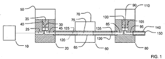
- Figure 1 is a schematic diagram of a conventional system for liquid flow control in semiconductor applications.
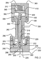
- Fig. 2 is a schematic diagram of a liquid flow control and liquid shutoff apparatus of the present disclosure in its preferred embodiment.
- Like reference characters will be used for like elements throughout the figures.
- a source of liquid, 10, under pressure is connected to a liquid shutoff valve, shown generally located at 20. Downstream of the liquid shutoff valve is a liquid flow sensor, shown generally at 60 and a liquid flow control valve, shown generally at 80. All parts of the system are connected by small-diameter tubing as shown in Figure 1 .
- the connecting tubing is typically made of stainless steel.
- Shutoff valve 20 generally includes an inlet flow passageway, 25, for liquid from source 10 to flow into the valve, a flow control orifice, 30, a movable solid member, 35, with an O-ring seal 40 for liquid shutoff, and an outlet flow passageway, 45, for the liquid to flow out of shutoff valve 20.
- valve 20 When valve 20 is in its open position, as shown in Figure 1 , the pressurized liquid in source 10 will flow into passageway 25, then through orifice 30, into flow passageway 45, and then out of shutoff valve 20.
- the solid movable member, 35 can be moved by an actuating mechanism 50 in a direction towards the orifice 30 to close the valve and away from the orifice to open the valve. The valve can thus be turned on and off to allow liquid from source 10 to flow through the valve on an as needed basis.
- the actuating mechanism, 50 usually includes an internal spring, which is not shown.
- the internal spring When the electrical power is turned off to actuating mechanism 50, the internal spring will exert a force to press the movable solid member 35 firmly against the orifice 30 to close the valve.
- Such a valve is usually referred as a normally closed valve.
- the actuation mechanism, 50 may include an electrical solenoid to create an electrical force to overcome the force of the spring and move movable solid member 35 away from its normally closed position to the open position shown in Figure 1 .
- a pneumatic piston operated by compressed gas pressure can be used to create the force needed to counter the force of the spring and move the valve to its open position.
- An electrically operated pilot mechanism can be used in conjunction with the piston to turn the compressed gas on or off electrically to move the piston in the desired direction in order for the valve to open or close.
- Flow sensor 60 usually includes a sensor tube 65 inside housing 70.
- the actual flow sensing mechanism and the associated electronic circuitry are usually placed in the same housing in order to generate an electrical signal output in response to the rate of liquid flowing through sensor 60.
- the most widely used sensing mechanism is that of the thermal type which senses the rate of liquid flow in a heated sensor tube by the thermal effect created by the flowing liquid stream. This response is detected electronically by means of the sensing mechanism and the electronic circuitry.
- Another widely used liquid flow sensor is a Coriolis force sensor which produces an electrical output signal in response to the mechanical effect created by the Coriolis force resulting from a flowing liquid passing through a vibrating sensor tube.
- the operating principles of these liquid flow sensing techniques are well known to those skilled in the art of liquid flow sensor design. It will not be further described in this disclosure.
- Flow control valve 80 like liquid shutoff valve 20, also includes an inlet flow passageway, 85, a control orifice, 90, an outlet flow passageway, 95, and a movable solid member 100, which is provided with an O-ring seal 105, and an actuating mechanism, 110 for moving the movable solid member, 100.
- the actuating mechanism 110 of the flow control valve 80 must be capable of moving the movable solid member 100 to a range of intermediate positions between its fully closed to its fully open position.
- the movement must also be very precise, so that the actuation mechanism can maintain its position in a precise location to control the rate of liquid flow to a specific value.
- the movement from one position to another must also be very fast, so that the response speed of the flow control system will also be very fast.
- a precise, accurate and fast actuating mechanism 110 must be used to control the movement of the movable solid member 100 in flow control valve, 80.
- an electrical solenoid or a piezoelectric transducer is often used to produce the required mechanical movement for precise liquid flow control. Both are capable of producing a small, but precise mechanical movement in response to an electrical input signal.
- the movement is produced by the expansion or contraction of solid material having a piezoelectric effect.
- the solid will expand or contract in response to a DC applied voltage signal.
- the flow sensor output voltage can be compared with a set-point voltage so that the input DC voltage can be adjusted until the sensor output voltage is equal to the set-point value.
- the liquid flow rate can be controlled and set to a specific value within its operating flow range and maintained at that value over the time period the desired liquid flow rate is to be maintained.
- the amount of liquid in the dead volume in the conventional liquid flow control system of Figure 1 can be quite large in systems that are not well designed.
- a typical dead volume in a well designed system is on the order of 100 ⁇ l. In systems that are not well designed, the dead volume can be much larger. Dead volume in the thousands of microliters range is not uncommon. If the flow control system of Figure 1 is placed in a standby position for a sufficiently long period of time, the dead volume, which is filled with liquid during operation, can become completely empty, due to liquid leakage from the dead volume through control valve 70, which is open during standby.
- the initial liquid flow from pressurized source 10 will first flow into this empty dead volume space to fill it, before the liquid can reach the end 150 of delivery tube 140, for the liquid to flow into the vaporizer to generate vapor. If the system has been placed on standby only for a short period of time, only a small amount of liquid will leak through control valve 80. Upon restart, it will take the liquid flow only a short time to fill the empty dead volume.
- the actual liquid delivered to the vapor generating vaporizer downstream can thus vary greatly depending on the degree to which the dead volume is filled with liquid before the liquid flow is restarted again. This will introduce a degree of variability in the actual rate of liquid delivery into the vaporizer in an otherwise accurate and precise liquid flow control system.
- a total dead volume of 100 ⁇ l will take a liquid flow at 100 ⁇ l/min to fill the empty dead volume. This means that upon start, the liquid flow of 100 ⁇ l/min will not reach outlet 150 of delivery tube 140 until 1 minute later. A delay of 1 minute, or 60 seconds, will be quite detrimental in most applications.
- This difficulty is normally overcome by installing a diverter valve at the output of the vaporizer that can be operated to direct the vaporizer output gas/vapor mixture to the vacuum pump until a desired diverting period is reached, at which point the diverter valve can be operated to deliver the gas/vapor mixture into the deposition chamber for film deposition.
- the diverter valve must be operated for a period of 1.0 minute, before the valve can be directed to deliver the gas/vapor mixture to the film deposition chamber in the deposition tool.
- time and material (liquid) are both wasted in order to overcome the problem created by the dead volume of the liquid delivery system.
- the problem of the dead volume can be partially overcome by designing the liquid delivery system to minimize the internal dead volume of the system. While the problem can be minimized, it cannot be totally eliminated. The effort needed to overcome the dead volume issue sometimes can be quite substantial in the conventional system shown in Figure 1 .
- the size of drop with weight sufficient to overcome the surface tension of the liquid depends will depend on the liquid density, its surface tension as well as the diameter of delivery tube 140.
- a typical drop size is on the order of 50 ⁇ l for a liquid such as water.
- 50 ⁇ l drops will form at the rate of 2 drops per minute, leading to pulses of vapor being generated at the rate of 2 pulses per minute.
- the apparatus of Figure 2 can be used.
- FIG. 2 illustrates a new, novel system making use of a combined liquid flow control and shutoff apparatus for controlling the rate of liquid flow and liquid shutoff.
- the apparatus is shown generally located at 200. Unless otherwise stated, all parts of the system are cylindrical in shape with a circular, i.e. round, cross-section. The parts are typically made of stainless steel.
- the apparatus is comprised of a lower body piece, 210, a flexible solid member in the form of a circular metal diaphragm, 220, held firmly in place by compression piece 270, and middle body piece 260, by means of screws 280. When screws 280 are tightened, compression piece 270 will press tightly against the edge of diaphragm 220 to form a compression seal around the edge of metal diaphragm 220.
- the lower body piece 210 is provided with an inlet liquid flow passageway 240 allowing a pressurized liquid from an external source, which is not shown, to flow through into space 230 under the diaphragm.
- the liquid then flows through an outlet flow passageway 250 which also functions as a liquid delivery tube.
- the liquid flowing out of outlet flow passageway 250 then flows into a downstream vapor generating apparatus, which is also not shown.
- Flow passageway 250 has an inlet 245 forming an orifice from which liquid in space 230 can enter and an outlet 255 through which the liquid can exit for delivery to an external vapor generating apparatus, which is also not shown.
- the middle body piece, 260 is provided with a piezoelectric transducer, 310, that has an upper end, 330, and a lower end, 340.
- Transducer 310 is held firmly in place between an inside surface 335 in the middle body piece, 260, which serves as an upper stop, while the lower end, 340, is firmly pressed against diaphragm 220.
- the diaphragm is flexible and acts like a spring to hold the piezoelectric transducer between its two ends. When a DC voltage is applied through a pair of input wires 320, the piezoelectric transducer will expand causing its length to increase.
- the increased length of the piezoelectric transducer will cause its lower end, 340, which is in contact with diaphragm 220, to move, thus moving diaphragm downward, thereby reducing the width of gap 225 separating the lower surface 222 of diaphragm 220 and orifice inlet 245 of flow passageway 250. Since the pressurized liquid in the external source is kept at a constant pressure, reducing the gap space 225 will cause the rate of liquid flow through inlet orifice 245 to decrease. When a sufficiently high DC voltage is applied to the piezoelectric transducer the diaphragm will move to close the gap, thereby changing the liquid flow rate to a near zero value. By this means, the rate of liquid flow through the apparatus can change from near zero to some upper limit by simply changing the applied DC voltage on the piezoelectric transducer.
- the gap space 225 is very small. Typically it is less than approximately 0.1 mm. For clarity the gap space shown in Figure 1 is greatly enlarged in order to show the design in greater detail. Other parts of the lower body piece 210, such as the length of the flow passageway 250, and its diameter are also greatly enlarged to show the design in greater detail for clarity.
- apparatus 200 of the present disclosure also includes a liquid shutoff mechanism contained within the upper body piece 360.
- Upper body piece 360 encloses a spring 370, which presses against a movable pneumatic piston, 380, which is provided with O-ring seals 410 and 420 around its periphery as shown in Figure 2 .
- a compressed gas is introduced into the upper body piece 360 through gas inlet 390 from an external compressed gas source, which is not shown, the compressed gas will flow into the upper body piece 360 to exert a force through piston 380 against the force of the spring 370.
- the piston 380 will thus have its lower end 430 lifted upward and away from the piezoelectric transducer 310 as shown in Figure 2 .
- the force of spring 370 will cause the lower end, 420, of piston 380 to move downward to push the piezoelectric transducer 310 down.
- This in turn causes the lower end 340 of the piezoelectric transducer, which is in contact with diaphragm 220, to push the center of diaphragm 220, which is flexible, to also move down to close gap 225, to shutoff the liquid flow.
- the apparatus of Figure 2 is in its standby shutoff position.
- the apparatus is designed to have a strong spring 370, so that the strong force of the spring will cause the liquid flow to be completely shutoff.
- the apparatus of Figure 2 can thus function as a positive liquid shutoff valve in its normal standby position, or when power is turned off.
- the apparatus can function as a flow rate control valve since the lower end 430 of piston 380 is then lifted off of piezoelectric transducer 310 by means of compressed gas pressure.
- the combination flow control/flow shutoff apparatus of Figure 2 will lead to cost savings because of the reduced number of separate components needed for liquid flow control and shutoff. More importantly, the liquid dead volume will be greatly reduced. Liquid dead volume of ⁇ 10 ⁇ l is easily achievable and dead volume as low as 2 ⁇ l has been achieved through careful design.
- liquid flowing out of the end 150 of liquid delivery tube 140 of Fig. 1 will form a drop due to the surface tension of the liquid. As more liquid flows into the drop, which is attached to the end of tube 140 by surface tension, the drop will thus become larger. When enough liquid has accumulated in the drop, the weight of the drop will overcome the force of liquid surface tension, causing the drop to detach from the end of delivery tube 140 to form a free falling drop. The output of such a liquid delivery system will no longer be steady, but in the form of discrete individual drops, falling off of the end of the delivery tube 140 at periodic intervals.
- the liquid flow passageway 250 serves as the liquid delivery tube, with outlet 255 at which a liquid drop will also form due to liquid surface tension.
- the apparatus of Fig. 2 of the present disclosure also includes an inlet gas flow passageway 290.
- a compressed gas source When a compressed gas source is connected to gas flow passage 290, the gas will flow out of the outlet orifice 300 creating a high velocity gas jet.
- This high velocity gas jet will create a shear force to cause the liquid accumulating at the end of capillary tube 250 to form a drop to be quickly sheared away as soon as liquid begins to accumulate at the outlet 255.
- the unsteady liquid flow resulting from liquid surface tension can be largely overcome, though not totally eliminated, by such an apparatus.
- the gas velocity needed to detach the liquid drop from end 255 depends on the gas, the liquid's molecular weight and the design of the gas flow system around end 155 of delivery tube 250.
- tube 250 is centrally located in gas orifice 300 sonic speed is the most effective.
- a gas velocity as low as 5 to 10% of the speed of sound can be quite effective.
- a gas velocity of ⁇ 20 m/s can be effectively used.
- apparatus of Figure 2 is particularly useful for liquid flow control, the same apparatus can also be used for the control of a gas flow in some applications.
- the apparatus is useful for the control of liquid, especially at a low flow rate.
- the same design and the feature are also useful for controlling liquid flow at a high rate.
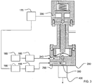
- Fig. 3 shows a typical system making use of apparatus of Fig. 2 to control the rate of gas and liquid flow to generate vapor for thin film deposition.
- the liquid flow control and shutoff apparatus of the present disclosure is shown generally located at 200.
- Source 180 is a source of liquid under pressure. It is connected to a liquid flow sensor 185, which in turn is connected to the liquid inlet flow passageway 240 in apparatus 200.
- a compressed gas source 170 connected to the gas inlet passageway 390 to provide compressed gas to operate the pneumatic piston in the apparatus as previously described.
- Compressed gas source 190 is connected to gas flow controller 190, which is connected in turn to the inlet gas flow passageway 290 to provide the carrier gas needed to operate the apparatus.
- the gas and liquid flowing out of the outlet 390 then flow into the heated vaporization chamber of the vaporizer 400 as shown in Figure 3 to generate a gas/vapor mixture for thin film deposition on a substrate.
Landscapes
- Engineering & Computer Science (AREA)
- General Engineering & Computer Science (AREA)
- Mechanical Engineering (AREA)
- Manufacturing & Machinery (AREA)
- Condensed Matter Physics & Semiconductors (AREA)
- General Physics & Mathematics (AREA)
- Physics & Mathematics (AREA)
- Computer Hardware Design (AREA)
- Microelectronics & Electronic Packaging (AREA)
- Power Engineering (AREA)
- Flow Control (AREA)
- Measuring Volume Flow (AREA)
- Fluid-Driven Valves (AREA)
- Electrically Driven Valve-Operating Means (AREA)
Applications Claiming Priority (3)
| Application Number | Priority Date | Filing Date | Title |
|---|---|---|---|
| US201261609616P | 2012-03-12 | 2012-03-12 | |
| US13/785,819 US8783652B2 (en) | 2012-03-12 | 2013-03-05 | Liquid flow control for film deposition |
| EP20130158156 EP2639483A3 (en) | 2012-03-12 | 2013-03-07 | Liquid flow control for film deposition |
Related Parent Applications (1)
| Application Number | Title | Priority Date | Filing Date |
|---|---|---|---|
| EP20130158156 Division EP2639483A3 (en) | 2012-03-12 | 2013-03-07 | Liquid flow control for film deposition |
Publications (2)
| Publication Number | Publication Date |
|---|---|
| EP3040591A1 EP3040591A1 (en) | 2016-07-06 |
| EP3040591B1 true EP3040591B1 (en) | 2018-01-03 |
Family
ID=47900664
Family Applications (2)
| Application Number | Title | Priority Date | Filing Date |
|---|---|---|---|
| EP16150020.2A Active EP3040591B1 (en) | 2012-03-12 | 2013-03-07 | Liquid flow control for film deposition |
| EP20130158156 Withdrawn EP2639483A3 (en) | 2012-03-12 | 2013-03-07 | Liquid flow control for film deposition |
Family Applications After (1)
| Application Number | Title | Priority Date | Filing Date |
|---|---|---|---|
| EP20130158156 Withdrawn EP2639483A3 (en) | 2012-03-12 | 2013-03-07 | Liquid flow control for film deposition |
Country Status (4)
| Country | Link |
|---|---|
| US (1) | US8783652B2 (enExample) |
| EP (2) | EP3040591B1 (enExample) |
| JP (1) | JP5725482B2 (enExample) |
| KR (1) | KR101432243B1 (enExample) |
Families Citing this family (21)
| Publication number | Priority date | Publication date | Assignee | Title |
|---|---|---|---|---|
| US9308307B2 (en) | 2007-09-13 | 2016-04-12 | Fresenius Medical Care Holdings, Inc. | Manifold diaphragms |
| US9358331B2 (en) | 2007-09-13 | 2016-06-07 | Fresenius Medical Care Holdings, Inc. | Portable dialysis machine with improved reservoir heating system |
| US8114288B2 (en) | 2007-11-29 | 2012-02-14 | Fresenlus Medical Care Holdings, Inc. | System and method for conducting hemodialysis and hemofiltration |
| US8105487B2 (en) | 2007-09-25 | 2012-01-31 | Fresenius Medical Care Holdings, Inc. | Manifolds for use in conducting dialysis |
| US8240636B2 (en) | 2009-01-12 | 2012-08-14 | Fresenius Medical Care Holdings, Inc. | Valve system |
| US8597505B2 (en) | 2007-09-13 | 2013-12-03 | Fresenius Medical Care Holdings, Inc. | Portable dialysis machine |
| EP3586946B1 (en) | 2008-10-07 | 2023-03-29 | Fresenius Medical Care Holdings, Inc. | Priming system and method for dialysis systems |
| CA2928208A1 (en) | 2008-10-30 | 2010-06-03 | Fresenius Medical Care Holdings, Inc. | Modular, portable dialysis system |
| WO2010114932A1 (en) | 2009-03-31 | 2010-10-07 | Xcorporeal, Inc. | Modular reservoir assembly for a hemodialysis and hemofiltration system |
| US9201036B2 (en) | 2012-12-21 | 2015-12-01 | Fresenius Medical Care Holdings, Inc. | Method and system of monitoring electrolyte levels and composition using capacitance or induction |
| US9157786B2 (en) | 2012-12-24 | 2015-10-13 | Fresenius Medical Care Holdings, Inc. | Load suspension and weighing system for a dialysis machine reservoir |
| US9354640B2 (en) * | 2013-11-11 | 2016-05-31 | Fresenius Medical Care Holdings, Inc. | Smart actuator for valve |
| EP3540280A4 (en) * | 2016-11-08 | 2019-11-27 | Fujikin Incorporated | VALVE DEVICE, METHOD FOR CONTROLLING THE FLOW RATE WITH THIS VALVE DEVICE AND METHOD FOR PRODUCING A SEMICONDUCTOR |
| CN110023659B (zh) * | 2016-11-30 | 2021-01-29 | 株式会社富士金 | 阀装置、使用该阀装置的流量控制方法和半导体制造方法 |
| KR102210582B1 (ko) * | 2017-09-25 | 2021-02-02 | 가부시키가이샤 후지킨 | 밸브장치, 유량 조정방법, 유체 제어장치, 유량 제어방법, 반도체 제조장치 및 반도체 제조방법 |
| CN111373182A (zh) * | 2017-11-24 | 2020-07-03 | 株式会社富士金 | 阀装置以及使用该阀装置的控制装置的控制方法、流体控制装置以及半导体制造装置 |
| DE102018001048A1 (de) * | 2018-02-09 | 2019-08-14 | Atlas Copco Ias Gmbh | Dosierventil |
| JP7030359B2 (ja) * | 2018-03-09 | 2022-03-07 | 株式会社フジキン | バルブ装置 |
| IL268254B2 (en) * | 2019-07-24 | 2024-10-01 | Ham Let Israel Canada Ltd | Fluid-flow control device |
| JP7684219B2 (ja) * | 2019-09-25 | 2025-05-27 | 芝浦機械株式会社 | 流量調整バルブ、ポンプユニット及び表面処理装置 |
| JP2024158856A (ja) * | 2023-04-28 | 2024-11-08 | 株式会社堀場エステック | 流体制御弁、流体制御装置、及び、材料供給システム |
Family Cites Families (16)
| Publication number | Priority date | Publication date | Assignee | Title |
|---|---|---|---|---|
| US5092360A (en) * | 1989-11-14 | 1992-03-03 | Hitachi Metals, Ltd. | Flow rated control valve using a high-temperature stacked-type displacement device |
| JPH0784662B2 (ja) * | 1989-12-12 | 1995-09-13 | アプライドマテリアルズジャパン株式会社 | 化学的気相成長方法とその装置 |
| DE69312436T2 (de) * | 1992-12-15 | 1998-02-05 | Applied Materials Inc | Verdampfung von flüssigen Reaktionspartnern für CVD |
| JPH08200525A (ja) * | 1995-01-31 | 1996-08-06 | Hitachi Metals Ltd | 液体原料気化器用弁 |
| JPH1089532A (ja) * | 1995-12-13 | 1998-04-10 | Rintetsuku:Kk | 気化装置の弁構造 |
| JPH11319660A (ja) * | 1998-05-15 | 1999-11-24 | Rintec:Kk | 気化装置 |
| KR100649852B1 (ko) | 1999-09-09 | 2006-11-24 | 동경 엘렉트론 주식회사 | 기화기 및 이것을 이용한 반도체 제조 시스템 |
| JP2001317646A (ja) * | 2000-05-08 | 2001-11-16 | Smc Corp | 圧電式流体制御弁 |
| JP2004092824A (ja) * | 2002-09-02 | 2004-03-25 | Fujikin Inc | 流体制御器 |
| JP2005113221A (ja) * | 2003-10-08 | 2005-04-28 | Lintec Co Ltd | 気化器並びにこれを用いた液体気化供給装置 |
| DE602004026334D1 (de) * | 2003-10-17 | 2010-05-12 | Sundew Technologies Llc | Ausfallsicheres, pneumatisch betätigtes ventil |
| JP4743763B2 (ja) * | 2006-01-18 | 2011-08-10 | 株式会社フジキン | 圧電素子駆動式金属ダイヤフラム型制御弁 |
| JP4933936B2 (ja) * | 2007-03-30 | 2012-05-16 | 株式会社フジキン | 圧電素子駆動式制御弁 |
| DE502007004403D1 (de) | 2007-08-03 | 2010-08-26 | Georg Fischer Wavin Ag | Ventilanordnung mit Drehmomentbegrenzer |
| DE112011100462T5 (de) | 2010-02-05 | 2012-11-22 | Msp Corp. | Feintröpfchen-Zerstäuber für die Flüssigprekursor-Verdampfung |
| US20130000759A1 (en) * | 2011-06-30 | 2013-01-03 | Agilent Technologies, Inc. | Microfluidic device and external piezoelectric actuator |
-
2013
- 2013-03-05 US US13/785,819 patent/US8783652B2/en active Active
- 2013-03-07 EP EP16150020.2A patent/EP3040591B1/en active Active
- 2013-03-07 EP EP20130158156 patent/EP2639483A3/en not_active Withdrawn
- 2013-03-11 JP JP2013048065A patent/JP5725482B2/ja active Active
- 2013-03-11 KR KR1020130025646A patent/KR101432243B1/ko active Active
Non-Patent Citations (1)
| Title |
|---|
| None * |
Also Published As
| Publication number | Publication date |
|---|---|
| EP2639483A2 (en) | 2013-09-18 |
| JP5725482B2 (ja) | 2015-05-27 |
| KR20130105419A (ko) | 2013-09-25 |
| EP3040591A1 (en) | 2016-07-06 |
| EP2639483A3 (en) | 2015-01-07 |
| US20130233395A1 (en) | 2013-09-12 |
| KR101432243B1 (ko) | 2014-09-23 |
| US8783652B2 (en) | 2014-07-22 |
| JP2013210095A (ja) | 2013-10-10 |
Similar Documents
| Publication | Publication Date | Title |
|---|---|---|
| EP3040591B1 (en) | Liquid flow control for film deposition | |
| US20250146851A1 (en) | Flow control system, method, and apparatus | |
| US6152168A (en) | Pressure-type flow rate control apparatus | |
| US11073846B2 (en) | Mass flow controller with absolute and differential pressure transducer | |
| JP5350824B2 (ja) | 液体材料の気化供給システム | |
| US8573560B2 (en) | Vacuum control valve and vacuum control system | |
| GB2386704A (en) | Pressure-based mass flow controller system | |
| US10838435B2 (en) | Pressure-type flow rate control device | |
| JP2004505331A (ja) | パイプライン用圧力制御装置 | |
| KR102412788B1 (ko) | 유량 제어 장치 및 유량 제어 방법 | |
| CN106662883A (zh) | 质量流量控制装置 | |
| WO2011119952A2 (en) | Integrated system for vapor generation and thin film deposition | |
| JP3619187B2 (ja) | 流量制御装置と流量制御方法 | |
| JP7382054B2 (ja) | バルブ装置および流量制御装置 | |
| KR20230007427A (ko) | 무전환 가스 도징 (divertless gas-dosing) | |
| JP2006319207A (ja) | 流量制御装置、薄膜堆積装置および流量制御方法 | |
| EP1914614B1 (en) | Proportional pressure control valve | |
| JP2003297765A (ja) | 液体気化装置および成膜装置 | |
| Johnson et al. | Development and Feasibility of a Variable-Area, Sonic Nozzle Mass Flow Controller | |
| JP2015056012A (ja) | ガバナー | |
| KR980011788A (ko) | 반도체 제조용 화학 기상 증착 장치 |
Legal Events
| Date | Code | Title | Description |
|---|---|---|---|
| PUAI | Public reference made under article 153(3) epc to a published international application that has entered the european phase |
Free format text: ORIGINAL CODE: 0009012 |
|
| AC | Divisional application: reference to earlier application |
Ref document number: 2639483 Country of ref document: EP Kind code of ref document: P |
|
| AK | Designated contracting states |
Kind code of ref document: A1 Designated state(s): AL AT BE BG CH CY CZ DE DK EE ES FI FR GB GR HR HU IE IS IT LI LT LU LV MC MK MT NL NO PL PT RO RS SE SI SK SM TR |
|
| 17P | Request for examination filed |
Effective date: 20170103 |
|
| RBV | Designated contracting states (corrected) |
Designated state(s): AL AT BE BG CH CY CZ DE DK EE ES FI FR GB GR HR HU IE IS IT LI LT LU LV MC MK MT NL NO PL PT RO RS SE SI SK SM TR |
|
| RIC1 | Information provided on ipc code assigned before grant |
Ipc: F16K 31/122 20060101AFI20170329BHEP Ipc: C23C 16/40 20060101ALI20170329BHEP Ipc: F16K 7/14 20060101ALI20170329BHEP Ipc: H01L 21/02 20060101ALI20170329BHEP Ipc: F16K 31/00 20060101ALI20170329BHEP |
|
| GRAP | Despatch of communication of intention to grant a patent |
Free format text: ORIGINAL CODE: EPIDOSNIGR1 |
|
| INTG | Intention to grant announced |
Effective date: 20170623 |
|
| GRAS | Grant fee paid |
Free format text: ORIGINAL CODE: EPIDOSNIGR3 |
|
| GRAA | (expected) grant |
Free format text: ORIGINAL CODE: 0009210 |
|
| AC | Divisional application: reference to earlier application |
Ref document number: 2639483 Country of ref document: EP Kind code of ref document: P |
|
| AK | Designated contracting states |
Kind code of ref document: B1 Designated state(s): AL AT BE BG CH CY CZ DE DK EE ES FI FR GB GR HR HU IE IS IT LI LT LU LV MC MK MT NL NO PL PT RO RS SE SI SK SM TR |
|
| REG | Reference to a national code |
Ref country code: GB Ref legal event code: FG4D |
|
| REG | Reference to a national code |
Ref country code: CH Ref legal event code: EP Ref country code: AT Ref legal event code: REF Ref document number: 960602 Country of ref document: AT Kind code of ref document: T Effective date: 20180115 |
|
| REG | Reference to a national code |
Ref country code: IE Ref legal event code: FG4D |
|
| REG | Reference to a national code |
Ref country code: DE Ref legal event code: R096 Ref document number: 602013031849 Country of ref document: DE |
|
| REG | Reference to a national code |
Ref country code: NL Ref legal event code: MP Effective date: 20180103 |
|
| REG | Reference to a national code |
Ref country code: LT Ref legal event code: MG4D |
|
| PGFP | Annual fee paid to national office [announced via postgrant information from national office to epo] |
Ref country code: IE Payment date: 20180305 Year of fee payment: 6 |
|
| REG | Reference to a national code |
Ref country code: AT Ref legal event code: MK05 Ref document number: 960602 Country of ref document: AT Kind code of ref document: T Effective date: 20180103 |
|
| PG25 | Lapsed in a contracting state [announced via postgrant information from national office to epo] |
Ref country code: NL Free format text: LAPSE BECAUSE OF FAILURE TO SUBMIT A TRANSLATION OF THE DESCRIPTION OR TO PAY THE FEE WITHIN THE PRESCRIBED TIME-LIMIT Effective date: 20180103 |
|
| PG25 | Lapsed in a contracting state [announced via postgrant information from national office to epo] |
Ref country code: ES Free format text: LAPSE BECAUSE OF FAILURE TO SUBMIT A TRANSLATION OF THE DESCRIPTION OR TO PAY THE FEE WITHIN THE PRESCRIBED TIME-LIMIT Effective date: 20180103 Ref country code: HR Free format text: LAPSE BECAUSE OF FAILURE TO SUBMIT A TRANSLATION OF THE DESCRIPTION OR TO PAY THE FEE WITHIN THE PRESCRIBED TIME-LIMIT Effective date: 20180103 Ref country code: LT Free format text: LAPSE BECAUSE OF FAILURE TO SUBMIT A TRANSLATION OF THE DESCRIPTION OR TO PAY THE FEE WITHIN THE PRESCRIBED TIME-LIMIT Effective date: 20180103 Ref country code: CY Free format text: LAPSE BECAUSE OF FAILURE TO SUBMIT A TRANSLATION OF THE DESCRIPTION OR TO PAY THE FEE WITHIN THE PRESCRIBED TIME-LIMIT Effective date: 20180103 Ref country code: NO Free format text: LAPSE BECAUSE OF FAILURE TO SUBMIT A TRANSLATION OF THE DESCRIPTION OR TO PAY THE FEE WITHIN THE PRESCRIBED TIME-LIMIT Effective date: 20180403 |
|
| PG25 | Lapsed in a contracting state [announced via postgrant information from national office to epo] |
Ref country code: IS Free format text: LAPSE BECAUSE OF FAILURE TO SUBMIT A TRANSLATION OF THE DESCRIPTION OR TO PAY THE FEE WITHIN THE PRESCRIBED TIME-LIMIT Effective date: 20180503 Ref country code: GR Free format text: LAPSE BECAUSE OF FAILURE TO SUBMIT A TRANSLATION OF THE DESCRIPTION OR TO PAY THE FEE WITHIN THE PRESCRIBED TIME-LIMIT Effective date: 20180404 Ref country code: RS Free format text: LAPSE BECAUSE OF FAILURE TO SUBMIT A TRANSLATION OF THE DESCRIPTION OR TO PAY THE FEE WITHIN THE PRESCRIBED TIME-LIMIT Effective date: 20180103 Ref country code: SE Free format text: LAPSE BECAUSE OF FAILURE TO SUBMIT A TRANSLATION OF THE DESCRIPTION OR TO PAY THE FEE WITHIN THE PRESCRIBED TIME-LIMIT Effective date: 20180103 Ref country code: LV Free format text: LAPSE BECAUSE OF FAILURE TO SUBMIT A TRANSLATION OF THE DESCRIPTION OR TO PAY THE FEE WITHIN THE PRESCRIBED TIME-LIMIT Effective date: 20180103 Ref country code: PL Free format text: LAPSE BECAUSE OF FAILURE TO SUBMIT A TRANSLATION OF THE DESCRIPTION OR TO PAY THE FEE WITHIN THE PRESCRIBED TIME-LIMIT Effective date: 20180103 Ref country code: AT Free format text: LAPSE BECAUSE OF FAILURE TO SUBMIT A TRANSLATION OF THE DESCRIPTION OR TO PAY THE FEE WITHIN THE PRESCRIBED TIME-LIMIT Effective date: 20180103 Ref country code: BG Free format text: LAPSE BECAUSE OF FAILURE TO SUBMIT A TRANSLATION OF THE DESCRIPTION OR TO PAY THE FEE WITHIN THE PRESCRIBED TIME-LIMIT Effective date: 20180403 |
|
| REG | Reference to a national code |
Ref country code: DE Ref legal event code: R097 Ref document number: 602013031849 Country of ref document: DE |
|
| PG25 | Lapsed in a contracting state [announced via postgrant information from national office to epo] |
Ref country code: AL Free format text: LAPSE BECAUSE OF FAILURE TO SUBMIT A TRANSLATION OF THE DESCRIPTION OR TO PAY THE FEE WITHIN THE PRESCRIBED TIME-LIMIT Effective date: 20180103 Ref country code: IT Free format text: LAPSE BECAUSE OF FAILURE TO SUBMIT A TRANSLATION OF THE DESCRIPTION OR TO PAY THE FEE WITHIN THE PRESCRIBED TIME-LIMIT Effective date: 20180103 Ref country code: RO Free format text: LAPSE BECAUSE OF FAILURE TO SUBMIT A TRANSLATION OF THE DESCRIPTION OR TO PAY THE FEE WITHIN THE PRESCRIBED TIME-LIMIT Effective date: 20180103 Ref country code: EE Free format text: LAPSE BECAUSE OF FAILURE TO SUBMIT A TRANSLATION OF THE DESCRIPTION OR TO PAY THE FEE WITHIN THE PRESCRIBED TIME-LIMIT Effective date: 20180103 |
|
| REG | Reference to a national code |
Ref country code: CH Ref legal event code: PL |
|
| PLBE | No opposition filed within time limit |
Free format text: ORIGINAL CODE: 0009261 |
|
| STAA | Information on the status of an ep patent application or granted ep patent |
Free format text: STATUS: NO OPPOSITION FILED WITHIN TIME LIMIT |
|
| PG25 | Lapsed in a contracting state [announced via postgrant information from national office to epo] |
Ref country code: MC Free format text: LAPSE BECAUSE OF FAILURE TO SUBMIT A TRANSLATION OF THE DESCRIPTION OR TO PAY THE FEE WITHIN THE PRESCRIBED TIME-LIMIT Effective date: 20180103 Ref country code: CZ Free format text: LAPSE BECAUSE OF FAILURE TO SUBMIT A TRANSLATION OF THE DESCRIPTION OR TO PAY THE FEE WITHIN THE PRESCRIBED TIME-LIMIT Effective date: 20180103 Ref country code: DK Free format text: LAPSE BECAUSE OF FAILURE TO SUBMIT A TRANSLATION OF THE DESCRIPTION OR TO PAY THE FEE WITHIN THE PRESCRIBED TIME-LIMIT Effective date: 20180103 Ref country code: SM Free format text: LAPSE BECAUSE OF FAILURE TO SUBMIT A TRANSLATION OF THE DESCRIPTION OR TO PAY THE FEE WITHIN THE PRESCRIBED TIME-LIMIT Effective date: 20180103 Ref country code: SK Free format text: LAPSE BECAUSE OF FAILURE TO SUBMIT A TRANSLATION OF THE DESCRIPTION OR TO PAY THE FEE WITHIN THE PRESCRIBED TIME-LIMIT Effective date: 20180103 |
|
| REG | Reference to a national code |
Ref country code: BE Ref legal event code: MM Effective date: 20180331 |
|
| 26N | No opposition filed |
Effective date: 20181005 |
|
| GBPC | Gb: european patent ceased through non-payment of renewal fee |
Effective date: 20180403 |
|
| PG25 | Lapsed in a contracting state [announced via postgrant information from national office to epo] |
Ref country code: LU Free format text: LAPSE BECAUSE OF NON-PAYMENT OF DUE FEES Effective date: 20180307 |
|
| PG25 | Lapsed in a contracting state [announced via postgrant information from national office to epo] |
Ref country code: CH Free format text: LAPSE BECAUSE OF NON-PAYMENT OF DUE FEES Effective date: 20180331 Ref country code: GB Free format text: LAPSE BECAUSE OF NON-PAYMENT OF DUE FEES Effective date: 20180403 Ref country code: SI Free format text: LAPSE BECAUSE OF FAILURE TO SUBMIT A TRANSLATION OF THE DESCRIPTION OR TO PAY THE FEE WITHIN THE PRESCRIBED TIME-LIMIT Effective date: 20180103 Ref country code: BE Free format text: LAPSE BECAUSE OF NON-PAYMENT OF DUE FEES Effective date: 20180331 Ref country code: LI Free format text: LAPSE BECAUSE OF NON-PAYMENT OF DUE FEES Effective date: 20180331 |
|
| PG25 | Lapsed in a contracting state [announced via postgrant information from national office to epo] |
Ref country code: FR Free format text: LAPSE BECAUSE OF NON-PAYMENT OF DUE FEES Effective date: 20180331 |
|
| PG25 | Lapsed in a contracting state [announced via postgrant information from national office to epo] |
Ref country code: IE Free format text: LAPSE BECAUSE OF NON-PAYMENT OF DUE FEES Effective date: 20190307 Ref country code: MT Free format text: LAPSE BECAUSE OF NON-PAYMENT OF DUE FEES Effective date: 20180307 |
|
| PG25 | Lapsed in a contracting state [announced via postgrant information from national office to epo] |
Ref country code: TR Free format text: LAPSE BECAUSE OF FAILURE TO SUBMIT A TRANSLATION OF THE DESCRIPTION OR TO PAY THE FEE WITHIN THE PRESCRIBED TIME-LIMIT Effective date: 20180103 |
|
| PG25 | Lapsed in a contracting state [announced via postgrant information from national office to epo] |
Ref country code: PT Free format text: LAPSE BECAUSE OF FAILURE TO SUBMIT A TRANSLATION OF THE DESCRIPTION OR TO PAY THE FEE WITHIN THE PRESCRIBED TIME-LIMIT Effective date: 20180103 |
|
| PG25 | Lapsed in a contracting state [announced via postgrant information from national office to epo] |
Ref country code: HU Free format text: LAPSE BECAUSE OF FAILURE TO SUBMIT A TRANSLATION OF THE DESCRIPTION OR TO PAY THE FEE WITHIN THE PRESCRIBED TIME-LIMIT; INVALID AB INITIO Effective date: 20130307 Ref country code: MK Free format text: LAPSE BECAUSE OF NON-PAYMENT OF DUE FEES Effective date: 20180103 |
|
| PGFP | Annual fee paid to national office [announced via postgrant information from national office to epo] |
Ref country code: DE Payment date: 20241231 Year of fee payment: 13 |
|
| PGFP | Annual fee paid to national office [announced via postgrant information from national office to epo] |
Ref country code: FI Payment date: 20250314 Year of fee payment: 13 |