EP3040176A1 - Installation de fabrication - Google Patents
Installation de fabrication Download PDFInfo
- Publication number
- EP3040176A1 EP3040176A1 EP15197503.4A EP15197503A EP3040176A1 EP 3040176 A1 EP3040176 A1 EP 3040176A1 EP 15197503 A EP15197503 A EP 15197503A EP 3040176 A1 EP3040176 A1 EP 3040176A1
- Authority
- EP
- European Patent Office
- Prior art keywords
- tool
- molded skin
- robot
- carrier
- production plant
- Prior art date
- Legal status (The legal status is an assumption and is not a legal conclusion. Google has not performed a legal analysis and makes no representation as to the accuracy of the status listed.)
- Granted
Links
- 238000004519 manufacturing process Methods 0.000 title claims abstract description 51
- 239000006260 foam Substances 0.000 claims abstract description 31
- 239000007921 spray Substances 0.000 claims abstract description 8
- 239000007788 liquid Substances 0.000 claims abstract description 3
- 230000008859 change Effects 0.000 claims description 5
- 238000002347 injection Methods 0.000 claims description 4
- 239000007924 injection Substances 0.000 claims description 4
- 239000000463 material Substances 0.000 abstract description 3
- 239000008258 liquid foam Substances 0.000 description 3
- 230000008901 benefit Effects 0.000 description 2
- 230000006735 deficit Effects 0.000 description 2
- 239000012948 isocyanate Substances 0.000 description 2
- 150000002513 isocyanates Chemical class 0.000 description 2
- 238000000034 method Methods 0.000 description 2
- 230000008569 process Effects 0.000 description 2
- 238000013459 approach Methods 0.000 description 1
- 230000009286 beneficial effect Effects 0.000 description 1
- 239000000969 carrier Substances 0.000 description 1
- 238000004140 cleaning Methods 0.000 description 1
- 230000001419 dependent effect Effects 0.000 description 1
- 238000010586 diagram Methods 0.000 description 1
- 230000004069 differentiation Effects 0.000 description 1
- 230000000694 effects Effects 0.000 description 1
- 238000005187 foaming Methods 0.000 description 1
- 238000010438 heat treatment Methods 0.000 description 1
- 238000012432 intermediate storage Methods 0.000 description 1
- 238000005457 optimization Methods 0.000 description 1
- 229920005862 polyol Polymers 0.000 description 1
- 150000003077 polyols Chemical class 0.000 description 1
- 229920002635 polyurethane Polymers 0.000 description 1
- 239000004814 polyurethane Substances 0.000 description 1
- 238000002360 preparation method Methods 0.000 description 1
- 230000001681 protective effect Effects 0.000 description 1
- 239000000243 solution Substances 0.000 description 1
- 239000000126 substance Substances 0.000 description 1
Images

Classifications
-
- B—PERFORMING OPERATIONS; TRANSPORTING
- B29—WORKING OF PLASTICS; WORKING OF SUBSTANCES IN A PLASTIC STATE IN GENERAL
- B29C—SHAPING OR JOINING OF PLASTICS; SHAPING OF MATERIAL IN A PLASTIC STATE, NOT OTHERWISE PROVIDED FOR; AFTER-TREATMENT OF THE SHAPED PRODUCTS, e.g. REPAIRING
- B29C44/00—Shaping by internal pressure generated in the material, e.g. swelling or foaming ; Producing porous or cellular expanded plastics articles
- B29C44/34—Auxiliary operations
- B29C44/58—Moulds
-
- B—PERFORMING OPERATIONS; TRANSPORTING
- B29—WORKING OF PLASTICS; WORKING OF SUBSTANCES IN A PLASTIC STATE IN GENERAL
- B29C—SHAPING OR JOINING OF PLASTICS; SHAPING OF MATERIAL IN A PLASTIC STATE, NOT OTHERWISE PROVIDED FOR; AFTER-TREATMENT OF THE SHAPED PRODUCTS, e.g. REPAIRING
- B29C31/00—Handling, e.g. feeding of the material to be shaped, storage of plastics material before moulding; Automation, i.e. automated handling lines in plastics processing plants, e.g. using manipulators or robots
- B29C31/006—Handling moulds, e.g. between a mould store and a moulding machine
-
- B—PERFORMING OPERATIONS; TRANSPORTING
- B29—WORKING OF PLASTICS; WORKING OF SUBSTANCES IN A PLASTIC STATE IN GENERAL
- B29C—SHAPING OR JOINING OF PLASTICS; SHAPING OF MATERIAL IN A PLASTIC STATE, NOT OTHERWISE PROVIDED FOR; AFTER-TREATMENT OF THE SHAPED PRODUCTS, e.g. REPAIRING
- B29C33/00—Moulds or cores; Details thereof or accessories therefor
- B29C33/20—Opening, closing or clamping
-
- B—PERFORMING OPERATIONS; TRANSPORTING
- B29—WORKING OF PLASTICS; WORKING OF SUBSTANCES IN A PLASTIC STATE IN GENERAL
- B29C—SHAPING OR JOINING OF PLASTICS; SHAPING OF MATERIAL IN A PLASTIC STATE, NOT OTHERWISE PROVIDED FOR; AFTER-TREATMENT OF THE SHAPED PRODUCTS, e.g. REPAIRING
- B29C33/00—Moulds or cores; Details thereof or accessories therefor
- B29C33/34—Moulds or cores; Details thereof or accessories therefor movable, e.g. to or from the moulding station
-
- B—PERFORMING OPERATIONS; TRANSPORTING
- B29—WORKING OF PLASTICS; WORKING OF SUBSTANCES IN A PLASTIC STATE IN GENERAL
- B29C—SHAPING OR JOINING OF PLASTICS; SHAPING OF MATERIAL IN A PLASTIC STATE, NOT OTHERWISE PROVIDED FOR; AFTER-TREATMENT OF THE SHAPED PRODUCTS, e.g. REPAIRING
- B29C44/00—Shaping by internal pressure generated in the material, e.g. swelling or foaming ; Producing porous or cellular expanded plastics articles
- B29C44/02—Shaping by internal pressure generated in the material, e.g. swelling or foaming ; Producing porous or cellular expanded plastics articles for articles of definite length, i.e. discrete articles
- B29C44/12—Incorporating or moulding on preformed parts, e.g. inserts or reinforcements
- B29C44/1228—Joining preformed parts by the expanding material
-
- B—PERFORMING OPERATIONS; TRANSPORTING
- B29—WORKING OF PLASTICS; WORKING OF SUBSTANCES IN A PLASTIC STATE IN GENERAL
- B29C—SHAPING OR JOINING OF PLASTICS; SHAPING OF MATERIAL IN A PLASTIC STATE, NOT OTHERWISE PROVIDED FOR; AFTER-TREATMENT OF THE SHAPED PRODUCTS, e.g. REPAIRING
- B29C44/00—Shaping by internal pressure generated in the material, e.g. swelling or foaming ; Producing porous or cellular expanded plastics articles
- B29C44/34—Auxiliary operations
- B29C44/36—Feeding the material to be shaped
- B29C44/367—Feeding the material to be shaped using spray nozzles
-
- B—PERFORMING OPERATIONS; TRANSPORTING
- B29—WORKING OF PLASTICS; WORKING OF SUBSTANCES IN A PLASTIC STATE IN GENERAL
- B29C—SHAPING OR JOINING OF PLASTICS; SHAPING OF MATERIAL IN A PLASTIC STATE, NOT OTHERWISE PROVIDED FOR; AFTER-TREATMENT OF THE SHAPED PRODUCTS, e.g. REPAIRING
- B29C44/00—Shaping by internal pressure generated in the material, e.g. swelling or foaming ; Producing porous or cellular expanded plastics articles
- B29C44/34—Auxiliary operations
- B29C44/60—Measuring, controlling or regulating
-
- B—PERFORMING OPERATIONS; TRANSPORTING
- B29—WORKING OF PLASTICS; WORKING OF SUBSTANCES IN A PLASTIC STATE IN GENERAL
- B29K—INDEXING SCHEME ASSOCIATED WITH SUBCLASSES B29B, B29C OR B29D, RELATING TO MOULDING MATERIALS OR TO MATERIALS FOR MOULDS, REINFORCEMENTS, FILLERS OR PREFORMED PARTS, e.g. INSERTS
- B29K2075/00—Use of PU, i.e. polyureas or polyurethanes or derivatives thereof, as moulding material
-
- B—PERFORMING OPERATIONS; TRANSPORTING
- B29—WORKING OF PLASTICS; WORKING OF SUBSTANCES IN A PLASTIC STATE IN GENERAL
- B29L—INDEXING SCHEME ASSOCIATED WITH SUBCLASS B29C, RELATING TO PARTICULAR ARTICLES
- B29L2031/00—Other particular articles
- B29L2031/30—Vehicles, e.g. ships or aircraft, or body parts thereof
- B29L2031/3005—Body finishings
- B29L2031/3008—Instrument panels
Definitions
- the invention relates to a manufacturing plant for producing a component which consists of a molded skin, a carrier and a foam layer arranged between the molded skin and the carrier.
- Components which consist of a molded skin, a carrier and a foam layer arranged between the molded skin and the carrier can be used, for example, as a dashboard of a motor vehicle. So far, extremely complex manufacturing systems are used for the production of such a component, which consist of a variety of costly machine tools. Nevertheless, it has not yet been possible to fill out waiting times in terms of manufacturing technology or to avoid such waiting times. The waiting times are required to allow the originally liquid foam injected into the molded skin to cure, so that the carrier and the molded skin can cohesively bond to one another via the foam layer. When cured, polyol and isocyanate react to form polyurethane.
- the invention has for its object to provide an overall simplified manufacturing system that allows continuous and automated as possible largely without interruption the production of components that consist of a support, a molded skin and an existing between the carrier and the molded skin foam layer.
- the advantages of the invention are in particular in the very compact, limited to a narrow space execution of such a manufacturing plant, which also consists of only a few facilities and no longer requires numerous machine tools.
- the principle of "short distances" is used.
- An essential, inventive aspect is that at least one program-controlled robot is used, which is used to move the entire tool in different directions of movement and also opens and closes the individual tools. It is possible to separate the upper tool and the lower tool by means of the robot in each direction of movement from each other or to connect with each other and / or pivotally connected to each other about an axis of rotation.
- a combination of detachable connection and pivoting about an at least virtual axis of rotation is also within the scope of the invention.
- the lower tool and the upper tool are detachably connected to each other in each of the tools used, this can be achieved that no downtime occurs.
- the lower tools or upper tools can be equipped independently of each other and connected with each other in this way.
- the waiting time required for curing the foam layer is used in a noticeable way by the robot spending the closed tool for the time of curing in a parking position. Since the tool change is no longer performed on a rotary table, but the parking position is used for "intermediate storage", arise in the area of the rotary table also no more waiting time, as was the case so far.
- the workflows are simplified by the manufacturing plant according to the invention as a whole and the individual stations connected in a meaningful way, so that a process optimization is possible.
- the rotary table has only two or three processing positions.
- the rotary table has a very simple structure and nevertheless makes it possible to provide all the processing stations which are required for the production of the component consisting of a carrier, a molded skin and a foam layer arranged between carrier and molded skin.
- This design of the rotary table is a not inconsiderable aspect of the compact design of the manufacturing plant.
- the closed tools which are provided with the molded skin, the carrier and the foam layer can be spent in the tool magazine to remain there in the park position until the foam layer is fully cured and thus the component is completed. The component thus produced can then be removed from the tool.
- Another advantage of the tool magazine with the existing parking positions is that at least one of the parking positions can be used for a tool change. In the ongoing production process, it can happen again and again that individual tools must be replaced. An additional parking position within the tool magazine is helpful for this. In order to ensure that no downtime is required in the production, therefore, an additional parking position in the Tool magazine be kept in order to use this parking position for the aforementioned tool change can.
- a special embodiment of the invention is that the production plant has two robots, of which a first robot for handling the tool consisting of lower tool and upper tool and the second robot for applying the foam layer can be used. Through this division of labor of the robot optimum utilization of the manufacturing facility is achieved according to the invention.
- the second robot is also disposed within the spray booth.
- a hermetic seal of this part of the manufacturing plant can be achieved and the impairment of the operators operating in the environment can be minimized. This measure ultimately serves the safety of work and the protection of the operators and also allows a complete automation of the injection process.
- two different approaches can be selected, which are that the molded skin is inserted manually or by means of a robot in the lower tool and / or the carrier manually or by means of a robot in the upper tool.
- the use of a robot in this context allows a step towards full automation.
- an electric heater of the tool has been found to be particularly advantageous, since it can be implemented with relatively little energy and in a short time and thus allows rapid heating of the tool. The cycle times for the production of the component can thus be significantly reduced.
- a particularly advantageous embodiment of the production plant is to be seen in that the molded skin and the carrier are fixed by means of a vacuum-generating pneumatic device in the respective mold half.
- the manufacturing plant as a whole is electrically operable. Consequently, as far as possible all functions are carried out by means of electrical power, so that in this case a uniform energy source is available and thus the complexity of the entire manufacturing plant can be reduced.
- the FIG. 1 shows first an example of the possibility of executing a tool 5, of which several can be used in a manufacturing plant according to the invention.
- the tool 5 is in this case constructed substantially in two parts and consists of a lower tool 6, which is detachably connected to an upper tool 8 and pivotable about an axis of rotation 7.
- the axis of rotation 7 is not a constructional axis of rotation, but rather a virtual axis of rotation 7.
- a carrier 2 is hereby inserted into a cavity of the upper tool 8, which has its negative shape for precisely fitting the carrier 2.
- the support 2 opposite is located in the lower tool 6, a molded skin 3, which in turn is precisely inserted into a negative mold of the molded skin having cavity 22.
- a foam layer 4 of an originally liquid foam material is applied to the molded skin 3, which produces a cohesive connection between the support 2 and the molded skin 3 after the closing of the tool 5 by its curing.
- the illustrated component is the dashboard for a motor vehicle. Since this component has an undercut 21, the use of a slider 20 is required in the tool 5 shown. The slider 20 can therefore within the Lower tool 6 are moved in the direction of the double arrow A, so that the slider 20 can be reciprocated between one of the molded skin 3 and the finished component fixing and a releasing this position. A peculiarity of in FIG.
- 1 illustrated tool 5 is that the outside of the upper tool 8, a tool flange 23 is arranged, which allows the gripping of the entire upper tool 8 and the entire, closed tool 5 with a robot arm, so that the tool 5 is opened and closed by a robot 9 can be moved back and forth between different positions within the production line.
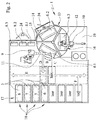
- FIG. 2 shows an embodiment of a complete manufacturing plant 1.
- This production plant 1 At the heart of this production plant 1 are initially two program-controlled robots 9 and 10, which are used in each case for different, automated tasks within the production plant 1.
- the robot 9 has a robot arm 11, while the robot 10 is equipped with a robot arm 12.
- the central processing station of the manufacturing plant 1 represents in the present example, a rotary table 13, which is equipped with three different positions. These are an assembly position 14, a connection position 15 and an injection position 16. As the term "round table” already clarifies, this is rotatable about a central axis of rotation.
- the method for producing a component which consists of a carrier 2, a molded skin 3 and a foam layer 4 arranged between the carrier 2 and the molded skin 3, in the present case runs off, initially by the robot 9, a lower tool 6.1 from a parking position 18 of a tool magazine 17 removed and transferred to the loading position 14 of the rotary table 13.
- the selected lower tool 6.1 can initially be removed from the parking position 18 of the tool magazine 17 in the direction of the arrow F and moved over a tool shuttle in the direction of the arrow E, so that it in the Engagement area of the robot 9 passes.
- the acquisition of the lower tool 6.1 by the robot 9 is in the FIG. 2 illustrated by the arrow C.
- the rotary table 13 is rotated by 120 ° in the clockwise direction, so that the tool 6.1 now comes into the engagement region of a first operator 24, which inserts the molded skin 3 in the lower tool 6.1.
- the next tool 6.1 is already transported by the robot 9 in the loading position 14 of the rotary table 13, so that the process runs continuously.
- the lower mold now having a molded skin 3 is denoted by 6.2 and subsequently brought by a renewed rotation of the rotary table 13 by 120 ° in the spray position 16, where within the hermetically sealed to the outside against the escape of chemical vapors spray booth 19 by the second robot 10th the liquid foam is injected into the molded skin 3.
- the sub-tool now designated for differentiation 6.3 is in the connecting position 15, where it is coupled to a previously loaded by a second operator 24 with a carrier 2 upper tool 8.1.
- the closing of the tool 5 by the upper tool 8.1 is pivoted about the virtual axis of rotation 7 and by means of in the representation of FIG. 2 not shown locking elements is fixed in a closed state.
- locking elements here clamping modules can be used.
- these activities are also performed by the robot 9, which subsequently delivers the closed tool 5 in the direction of the arrow D, so that it can be transferred via the tool shuttle in the direction of the arrow E into a parking position 18 of the tool magazine 17, where the Foam layer 4 hardens and thus produces the cohesive connection between the carrier 2 and the molded skin 3.
- the entire tool 5 can be returned to the rotary table 13 to open it by the robot 9, so that the removal of the finished component by means of the robot 9 or through the Operator 24 is possible. After a brief cleaning of the tool 5, this can be provided immediately thereafter for the next following production process.
- the robot 9 which subsequently delivers the closed tool 5 in the direction of the arrow D, so that it can be transferred via the tool shuttle in the direction of the arrow E into a parking position 18 of the tool magazine 17, where the Foam layer 4 hardens and thus produces the cohesive connection between the carrier 2 and the molded skin 3.
- the entire tool 5 can be returned to the rotary table 13 to open it by the robot 9, so that the removal of the finished component by means
Landscapes
- Engineering & Computer Science (AREA)
- Mechanical Engineering (AREA)
- Robotics (AREA)
- Casting Or Compression Moulding Of Plastics Or The Like (AREA)
Priority Applications (1)
| Application Number | Priority Date | Filing Date | Title |
|---|---|---|---|
| PL15197503T PL3040176T3 (pl) | 2014-12-19 | 2015-12-02 | Instalacja produkcyjna |
Applications Claiming Priority (1)
| Application Number | Priority Date | Filing Date | Title |
|---|---|---|---|
| DE202014106196.7U DE202014106196U1 (de) | 2014-12-19 | 2014-12-19 | Fertigungsanlage |
Publications (2)
| Publication Number | Publication Date |
|---|---|
| EP3040176A1 true EP3040176A1 (fr) | 2016-07-06 |
| EP3040176B1 EP3040176B1 (fr) | 2020-11-04 |
Family
ID=52470985
Family Applications (1)
| Application Number | Title | Priority Date | Filing Date |
|---|---|---|---|
| EP15197503.4A Active EP3040176B1 (fr) | 2014-12-19 | 2015-12-02 | Installation de fabrication |
Country Status (3)
| Country | Link |
|---|---|
| EP (1) | EP3040176B1 (fr) |
| DE (1) | DE202014106196U1 (fr) |
| PL (1) | PL3040176T3 (fr) |
Cited By (2)
| Publication number | Priority date | Publication date | Assignee | Title |
|---|---|---|---|---|
| CN106626212A (zh) * | 2017-01-18 | 2017-05-10 | 安徽信盟机电装备制造有限公司 | 一种带自动换模机构的箱体发泡设备 |
| EP3888867A1 (fr) * | 2020-04-02 | 2021-10-06 | STG Stanztechnik GmbH & Co.KG | Système de moulage par injection, système de production et procédé de fabrication de pièces moulées à partir de matières composés de moulage injectables ou expansibles |
Families Citing this family (4)
| Publication number | Priority date | Publication date | Assignee | Title |
|---|---|---|---|---|
| DE102016120784A1 (de) | 2016-11-01 | 2018-05-03 | Josef Weischer GmbH & Co. KG | Verfahren zur Herstellung von Verbundwerkstücken und Fertigungsanlage zur Anwendung der Verfahren |
| DE102016120788A1 (de) | 2016-11-01 | 2018-05-03 | Josef Weischer GmbH & Co. KG | Werkzeugträger und Fertigungsanlage mit einem derartigen Werkzeugträger |
| DE202017101352U1 (de) | 2017-03-09 | 2017-04-10 | Josef Weischer GmbH & Co. KG | Fertigungseinheit zur Herstellung von Formschaumteilen und Fertigungsanlage mit wenigstens einer derartigen Fertigungseinheit |
| DE102019120104A1 (de) * | 2019-07-25 | 2021-01-28 | Webasto SE | System und Verfahren zum Bearbeiten plattenförmiger Werkstücke für ein Kraftfahrzeug |
Citations (5)
| Publication number | Priority date | Publication date | Assignee | Title |
|---|---|---|---|---|
| DE1629746A1 (de) * | 1967-04-21 | 1971-02-04 | Desma Werke Gmbh | Spritzgiessanlage mit auswechselbaren Spritzgiessformen |
| DE19901114A1 (de) * | 1998-02-03 | 1999-08-05 | Ulysses Injection S R I | Spritzpreßmaschine |
| DE102005003074A1 (de) * | 2005-01-22 | 2006-07-27 | Zahoransky Gmbh Formen-Und Werkzeugbau | Spritzgießmaschine |
| WO2008104878A1 (fr) * | 2007-03-01 | 2008-09-04 | Ipotenusa S.R.L. | Système de fabrication de produits en plastique expansé tel que eva, notamment des semelles ou d'autres produits présentant des caractéristiques de légèreté et de confort |
| EP2153968A2 (fr) * | 2008-07-31 | 2010-02-17 | Krauss-Maffei Kunststofftechnik GmbH | Procédé de fabrication d'un produit à partir de matières de départ réactives |
-
2014
- 2014-12-19 DE DE202014106196.7U patent/DE202014106196U1/de not_active Expired - Lifetime
-
2015
- 2015-12-02 PL PL15197503T patent/PL3040176T3/pl unknown
- 2015-12-02 EP EP15197503.4A patent/EP3040176B1/fr active Active
Patent Citations (5)
| Publication number | Priority date | Publication date | Assignee | Title |
|---|---|---|---|---|
| DE1629746A1 (de) * | 1967-04-21 | 1971-02-04 | Desma Werke Gmbh | Spritzgiessanlage mit auswechselbaren Spritzgiessformen |
| DE19901114A1 (de) * | 1998-02-03 | 1999-08-05 | Ulysses Injection S R I | Spritzpreßmaschine |
| DE102005003074A1 (de) * | 2005-01-22 | 2006-07-27 | Zahoransky Gmbh Formen-Und Werkzeugbau | Spritzgießmaschine |
| WO2008104878A1 (fr) * | 2007-03-01 | 2008-09-04 | Ipotenusa S.R.L. | Système de fabrication de produits en plastique expansé tel que eva, notamment des semelles ou d'autres produits présentant des caractéristiques de légèreté et de confort |
| EP2153968A2 (fr) * | 2008-07-31 | 2010-02-17 | Krauss-Maffei Kunststofftechnik GmbH | Procédé de fabrication d'un produit à partir de matières de départ réactives |
Cited By (2)
| Publication number | Priority date | Publication date | Assignee | Title |
|---|---|---|---|---|
| CN106626212A (zh) * | 2017-01-18 | 2017-05-10 | 安徽信盟机电装备制造有限公司 | 一种带自动换模机构的箱体发泡设备 |
| EP3888867A1 (fr) * | 2020-04-02 | 2021-10-06 | STG Stanztechnik GmbH & Co.KG | Système de moulage par injection, système de production et procédé de fabrication de pièces moulées à partir de matières composés de moulage injectables ou expansibles |
Also Published As
| Publication number | Publication date |
|---|---|
| DE202014106196U1 (de) | 2015-01-26 |
| PL3040176T3 (pl) | 2022-07-11 |
| EP3040176B1 (fr) | 2020-11-04 |
Similar Documents
| Publication | Publication Date | Title |
|---|---|---|
| EP3040176B1 (fr) | Installation de fabrication | |
| DE102016209045B4 (de) | Verfahren und vorrichtung zum automatischen herstellen von schuhsohlen, sohlen und schuhe | |
| EP2337669B1 (fr) | Procédé et dispositif pour le dépôt et le drapage de sections d'une structure fibreuse de renfort pour la production d'une préforme profilée | |
| DE102012006502A1 (de) | Verfahren zum mehrstufigen Schleifen von Werkstücken, sowie Vakuumtisch, Vorratsbehälter, Abstreifeinrichtung und Anlage zur Durchführung des Verfahrens | |
| EP3442886B1 (fr) | Table de transfert rotative et procédé de transport d'objets | |
| DE102012110354A1 (de) | Formwerkzeug, Steuermittel, Verfahren und Anlage zum Herstellen eines, vorzugsweise faserverstärkten, Kunststoffbauteils | |
| EP3007884B1 (fr) | Dispositif de production d'une pièce constituée d'un matériau composite renforcé de fibres | |
| DE102016221821A1 (de) | Verfahren und Vorrichtung zur additiven Fertigung eines dreidimensionalen Werkstücks | |
| DE10022269A1 (de) | Verfahren und Vorrichtung zur Durchführung eines Produktwechsels bei Thermoformvorgängen | |
| DE10150092C1 (de) | Verfahren zum Beschicken von IHU-Pressen und Einrichtung zur Durchführung des Verfahrens | |
| WO2018019683A1 (fr) | Transporteur et procédé de transport d'objets de station de travail en station de travail dans une installation de production, et installation de production destinée à la fabrication de produits et dotée d'un tel transporteur | |
| EP3002103B1 (fr) | Dispositif de soudage de matière synthétique et procédé de soudage de matière synthétique associé | |
| EP3315276B1 (fr) | Procédé de fabrication de pièces composites et d'une unité de fabrication pour l'application des méthodes | |
| DE102007056690B4 (de) | Anlage zur Herstellung einer Leichtbaustruktur | |
| DE102019212679A1 (de) | Bereitstellungsmodul für eine 3D-Druckmaschine | |
| DE102009007703B4 (de) | Verfahren zum Herstellen eines Kunststoffbauteils mit Verstärkungsstruktur | |
| EP3129229B1 (fr) | Procédé et système de fabrication pour contre-coller des éléments intérieurs de véhicules | |
| EP3372369B1 (fr) | Unité de production pour la production de pièces moulées en mousse et d'une unité de fabrication avec au moins une telle unité de production | |
| DE102004059962A1 (de) | Verfahren und Vorrichtung zum Tiefziehen | |
| DE19631341A1 (de) | Verfahren und Maschine zum Realisieren von Kränzen von plattenförmigen Schleifelementen zum Formen von rotierenden Bürsten | |
| DE102018131368A1 (de) | Bereitstellungssystem, Verfahren zum Bestücken einer Zufuhrvorrichtung mit einem Beschichtungsmaterial und Verwendug eines Manipulators | |
| DE202016104347U1 (de) | Spritzgießmaschine zum Herstellen eines Mehrkomponenten-Kunststoffteils | |
| EP3991940A1 (fr) | Dispositif d'injection pourvu de table rotative et côté fermeture en trois parties | |
| DE1902786C3 (de) | Verfahren und Vorrichtung zum Zusammenfügen der beiden Maskenteile einer Formmaske | |
| DE102023106776A1 (de) | Greiferanordnung mit drehbarer Aufnahmeeinrichtung |
Legal Events
| Date | Code | Title | Description |
|---|---|---|---|
| PUAI | Public reference made under article 153(3) epc to a published international application that has entered the european phase |
Free format text: ORIGINAL CODE: 0009012 |
|
| AK | Designated contracting states |
Kind code of ref document: A1 Designated state(s): AL AT BE BG CH CY CZ DE DK EE ES FI FR GB GR HR HU IE IS IT LI LT LU LV MC MK MT NL NO PL PT RO RS SE SI SK SM TR |
|
| AX | Request for extension of the european patent |
Extension state: BA ME |
|
| RAP1 | Party data changed (applicant data changed or rights of an application transferred) |
Owner name: JOSEF WEISCHER GMBH & CO. KG |
|
| STAA | Information on the status of an ep patent application or granted ep patent |
Free format text: STATUS: REQUEST FOR EXAMINATION WAS MADE |
|
| 17P | Request for examination filed |
Effective date: 20161230 |
|
| RBV | Designated contracting states (corrected) |
Designated state(s): AL AT BE BG CH CY CZ DE DK EE ES FI FR GB GR HR HU IE IS IT LI LT LU LV MC MK MT NL NO PL PT RO RS SE SI SK SM TR |
|
| GRAP | Despatch of communication of intention to grant a patent |
Free format text: ORIGINAL CODE: EPIDOSNIGR1 |
|
| STAA | Information on the status of an ep patent application or granted ep patent |
Free format text: STATUS: GRANT OF PATENT IS INTENDED |
|
| RIC1 | Information provided on ipc code assigned before grant |
Ipc: B29C 44/58 20060101ALI20200506BHEP Ipc: B29C 44/60 20060101ALI20200506BHEP Ipc: B29C 44/36 20060101ALI20200506BHEP Ipc: B29C 31/00 20060101ALI20200506BHEP Ipc: B29C 33/34 20060101ALI20200506BHEP Ipc: B29C 33/20 20060101ALI20200506BHEP Ipc: B29C 44/42 20060101AFI20200506BHEP Ipc: B29K 75/00 20060101ALI20200506BHEP Ipc: B29C 44/12 20060101ALI20200506BHEP Ipc: B29L 31/30 20060101ALI20200506BHEP |
|
| INTG | Intention to grant announced |
Effective date: 20200526 |
|
| GRAS | Grant fee paid |
Free format text: ORIGINAL CODE: EPIDOSNIGR3 |
|
| GRAA | (expected) grant |
Free format text: ORIGINAL CODE: 0009210 |
|
| STAA | Information on the status of an ep patent application or granted ep patent |
Free format text: STATUS: THE PATENT HAS BEEN GRANTED |
|
| AK | Designated contracting states |
Kind code of ref document: B1 Designated state(s): AL AT BE BG CH CY CZ DE DK EE ES FI FR GB GR HR HU IE IS IT LI LT LU LV MC MK MT NL NO PL PT RO RS SE SI SK SM TR |
|
| REG | Reference to a national code |
Ref country code: GB Ref legal event code: FG4D Free format text: NOT ENGLISH |
|
| REG | Reference to a national code |
Ref country code: CH Ref legal event code: EP |
|
| REG | Reference to a national code |
Ref country code: AT Ref legal event code: REF Ref document number: 1330226 Country of ref document: AT Kind code of ref document: T Effective date: 20201115 |
|
| REG | Reference to a national code |
Ref country code: DE Ref legal event code: R096 Ref document number: 502015013743 Country of ref document: DE |
|
| REG | Reference to a national code |
Ref country code: IE Ref legal event code: FG4D Free format text: LANGUAGE OF EP DOCUMENT: GERMAN |
|
| REG | Reference to a national code |
Ref country code: NL Ref legal event code: MP Effective date: 20201104 |
|
| PG25 | Lapsed in a contracting state [announced via postgrant information from national office to epo] |
Ref country code: GR Free format text: LAPSE BECAUSE OF FAILURE TO SUBMIT A TRANSLATION OF THE DESCRIPTION OR TO PAY THE FEE WITHIN THE PRESCRIBED TIME-LIMIT Effective date: 20210205 Ref country code: RS Free format text: LAPSE BECAUSE OF FAILURE TO SUBMIT A TRANSLATION OF THE DESCRIPTION OR TO PAY THE FEE WITHIN THE PRESCRIBED TIME-LIMIT Effective date: 20201104 Ref country code: FI Free format text: LAPSE BECAUSE OF FAILURE TO SUBMIT A TRANSLATION OF THE DESCRIPTION OR TO PAY THE FEE WITHIN THE PRESCRIBED TIME-LIMIT Effective date: 20201104 Ref country code: PT Free format text: LAPSE BECAUSE OF FAILURE TO SUBMIT A TRANSLATION OF THE DESCRIPTION OR TO PAY THE FEE WITHIN THE PRESCRIBED TIME-LIMIT Effective date: 20210304 Ref country code: NO Free format text: LAPSE BECAUSE OF FAILURE TO SUBMIT A TRANSLATION OF THE DESCRIPTION OR TO PAY THE FEE WITHIN THE PRESCRIBED TIME-LIMIT Effective date: 20210204 |
|
| PGFP | Annual fee paid to national office [announced via postgrant information from national office to epo] |
Ref country code: IT Payment date: 20210225 Year of fee payment: 6 Ref country code: CZ Payment date: 20201221 Year of fee payment: 6 |
|
| PG25 | Lapsed in a contracting state [announced via postgrant information from national office to epo] |
Ref country code: IS Free format text: LAPSE BECAUSE OF FAILURE TO SUBMIT A TRANSLATION OF THE DESCRIPTION OR TO PAY THE FEE WITHIN THE PRESCRIBED TIME-LIMIT Effective date: 20210304 Ref country code: LV Free format text: LAPSE BECAUSE OF FAILURE TO SUBMIT A TRANSLATION OF THE DESCRIPTION OR TO PAY THE FEE WITHIN THE PRESCRIBED TIME-LIMIT Effective date: 20201104 Ref country code: SE Free format text: LAPSE BECAUSE OF FAILURE TO SUBMIT A TRANSLATION OF THE DESCRIPTION OR TO PAY THE FEE WITHIN THE PRESCRIBED TIME-LIMIT Effective date: 20201104 Ref country code: ES Free format text: LAPSE BECAUSE OF FAILURE TO SUBMIT A TRANSLATION OF THE DESCRIPTION OR TO PAY THE FEE WITHIN THE PRESCRIBED TIME-LIMIT Effective date: 20201104 Ref country code: BG Free format text: LAPSE BECAUSE OF FAILURE TO SUBMIT A TRANSLATION OF THE DESCRIPTION OR TO PAY THE FEE WITHIN THE PRESCRIBED TIME-LIMIT Effective date: 20210204 |
|
| REG | Reference to a national code |
Ref country code: LT Ref legal event code: MG9D |
|
| PG25 | Lapsed in a contracting state [announced via postgrant information from national office to epo] |
Ref country code: HR Free format text: LAPSE BECAUSE OF FAILURE TO SUBMIT A TRANSLATION OF THE DESCRIPTION OR TO PAY THE FEE WITHIN THE PRESCRIBED TIME-LIMIT Effective date: 20201104 |
|
| PG25 | Lapsed in a contracting state [announced via postgrant information from national office to epo] |
Ref country code: LT Free format text: LAPSE BECAUSE OF FAILURE TO SUBMIT A TRANSLATION OF THE DESCRIPTION OR TO PAY THE FEE WITHIN THE PRESCRIBED TIME-LIMIT Effective date: 20201104 Ref country code: SK Free format text: LAPSE BECAUSE OF FAILURE TO SUBMIT A TRANSLATION OF THE DESCRIPTION OR TO PAY THE FEE WITHIN THE PRESCRIBED TIME-LIMIT Effective date: 20201104 Ref country code: RO Free format text: LAPSE BECAUSE OF FAILURE TO SUBMIT A TRANSLATION OF THE DESCRIPTION OR TO PAY THE FEE WITHIN THE PRESCRIBED TIME-LIMIT Effective date: 20201104 Ref country code: SM Free format text: LAPSE BECAUSE OF FAILURE TO SUBMIT A TRANSLATION OF THE DESCRIPTION OR TO PAY THE FEE WITHIN THE PRESCRIBED TIME-LIMIT Effective date: 20201104 Ref country code: EE Free format text: LAPSE BECAUSE OF FAILURE TO SUBMIT A TRANSLATION OF THE DESCRIPTION OR TO PAY THE FEE WITHIN THE PRESCRIBED TIME-LIMIT Effective date: 20201104 |
|
| REG | Reference to a national code |
Ref country code: CH Ref legal event code: PL |
|
| REG | Reference to a national code |
Ref country code: DE Ref legal event code: R097 Ref document number: 502015013743 Country of ref document: DE |
|
| PG25 | Lapsed in a contracting state [announced via postgrant information from national office to epo] |
Ref country code: MC Free format text: LAPSE BECAUSE OF FAILURE TO SUBMIT A TRANSLATION OF THE DESCRIPTION OR TO PAY THE FEE WITHIN THE PRESCRIBED TIME-LIMIT Effective date: 20201104 Ref country code: DK Free format text: LAPSE BECAUSE OF FAILURE TO SUBMIT A TRANSLATION OF THE DESCRIPTION OR TO PAY THE FEE WITHIN THE PRESCRIBED TIME-LIMIT Effective date: 20201104 |
|
| REG | Reference to a national code |
Ref country code: BE Ref legal event code: MM Effective date: 20201231 |
|
| PLBE | No opposition filed within time limit |
Free format text: ORIGINAL CODE: 0009261 |
|
| STAA | Information on the status of an ep patent application or granted ep patent |
Free format text: STATUS: NO OPPOSITION FILED WITHIN TIME LIMIT |
|
| 26N | No opposition filed |
Effective date: 20210805 |
|
| GBPC | Gb: european patent ceased through non-payment of renewal fee |
Effective date: 20210204 |
|
| PG25 | Lapsed in a contracting state [announced via postgrant information from national office to epo] |
Ref country code: NL Free format text: LAPSE BECAUSE OF FAILURE TO SUBMIT A TRANSLATION OF THE DESCRIPTION OR TO PAY THE FEE WITHIN THE PRESCRIBED TIME-LIMIT Effective date: 20201104 Ref country code: LU Free format text: LAPSE BECAUSE OF NON-PAYMENT OF DUE FEES Effective date: 20201202 Ref country code: FR Free format text: LAPSE BECAUSE OF NON-PAYMENT OF DUE FEES Effective date: 20210104 Ref country code: AL Free format text: LAPSE BECAUSE OF FAILURE TO SUBMIT A TRANSLATION OF THE DESCRIPTION OR TO PAY THE FEE WITHIN THE PRESCRIBED TIME-LIMIT Effective date: 20201104 Ref country code: IE Free format text: LAPSE BECAUSE OF NON-PAYMENT OF DUE FEES Effective date: 20201202 |
|
| PG25 | Lapsed in a contracting state [announced via postgrant information from national office to epo] |
Ref country code: SI Free format text: LAPSE BECAUSE OF FAILURE TO SUBMIT A TRANSLATION OF THE DESCRIPTION OR TO PAY THE FEE WITHIN THE PRESCRIBED TIME-LIMIT Effective date: 20201104 Ref country code: CH Free format text: LAPSE BECAUSE OF NON-PAYMENT OF DUE FEES Effective date: 20201231 Ref country code: LI Free format text: LAPSE BECAUSE OF NON-PAYMENT OF DUE FEES Effective date: 20201231 |
|
| PG25 | Lapsed in a contracting state [announced via postgrant information from national office to epo] |
Ref country code: GB Free format text: LAPSE BECAUSE OF NON-PAYMENT OF DUE FEES Effective date: 20210204 |
|
| PGFP | Annual fee paid to national office [announced via postgrant information from national office to epo] |
Ref country code: DE Payment date: 20211111 Year of fee payment: 7 |
|
| REG | Reference to a national code |
Ref country code: AT Ref legal event code: MM01 Ref document number: 1330226 Country of ref document: AT Kind code of ref document: T Effective date: 20201202 |
|
| PG25 | Lapsed in a contracting state [announced via postgrant information from national office to epo] |
Ref country code: AT Free format text: LAPSE BECAUSE OF NON-PAYMENT OF DUE FEES Effective date: 20201202 |
|
| PG25 | Lapsed in a contracting state [announced via postgrant information from national office to epo] |
Ref country code: IS Free format text: LAPSE BECAUSE OF FAILURE TO SUBMIT A TRANSLATION OF THE DESCRIPTION OR TO PAY THE FEE WITHIN THE PRESCRIBED TIME-LIMIT Effective date: 20210304 Ref country code: TR Free format text: LAPSE BECAUSE OF FAILURE TO SUBMIT A TRANSLATION OF THE DESCRIPTION OR TO PAY THE FEE WITHIN THE PRESCRIBED TIME-LIMIT Effective date: 20201104 Ref country code: MT Free format text: LAPSE BECAUSE OF FAILURE TO SUBMIT A TRANSLATION OF THE DESCRIPTION OR TO PAY THE FEE WITHIN THE PRESCRIBED TIME-LIMIT Effective date: 20201104 Ref country code: CY Free format text: LAPSE BECAUSE OF FAILURE TO SUBMIT A TRANSLATION OF THE DESCRIPTION OR TO PAY THE FEE WITHIN THE PRESCRIBED TIME-LIMIT Effective date: 20201104 |
|
| PG25 | Lapsed in a contracting state [announced via postgrant information from national office to epo] |
Ref country code: MK Free format text: LAPSE BECAUSE OF FAILURE TO SUBMIT A TRANSLATION OF THE DESCRIPTION OR TO PAY THE FEE WITHIN THE PRESCRIBED TIME-LIMIT Effective date: 20201104 |
|
| PG25 | Lapsed in a contracting state [announced via postgrant information from national office to epo] |
Ref country code: CZ Free format text: LAPSE BECAUSE OF NON-PAYMENT OF DUE FEES Effective date: 20211202 Ref country code: BE Free format text: LAPSE BECAUSE OF NON-PAYMENT OF DUE FEES Effective date: 20201231 |
|
| PGFP | Annual fee paid to national office [announced via postgrant information from national office to epo] |
Ref country code: PL Payment date: 20201208 Year of fee payment: 6 |
|
| PG25 | Lapsed in a contracting state [announced via postgrant information from national office to epo] |
Ref country code: IT Free format text: LAPSE BECAUSE OF NON-PAYMENT OF DUE FEES Effective date: 20211202 |
|
| REG | Reference to a national code |
Ref country code: DE Ref legal event code: R119 Ref document number: 502015013743 Country of ref document: DE |
|
| PG25 | Lapsed in a contracting state [announced via postgrant information from national office to epo] |
Ref country code: DE Free format text: LAPSE BECAUSE OF NON-PAYMENT OF DUE FEES Effective date: 20230701 |
|
| PG25 | Lapsed in a contracting state [announced via postgrant information from national office to epo] |
Ref country code: PL Free format text: LAPSE BECAUSE OF NON-PAYMENT OF DUE FEES Effective date: 20211202 |