EP3038234A1 - Supporter for stator - Google Patents
Supporter for stator Download PDFInfo
- Publication number
- EP3038234A1 EP3038234A1 EP15200703.5A EP15200703A EP3038234A1 EP 3038234 A1 EP3038234 A1 EP 3038234A1 EP 15200703 A EP15200703 A EP 15200703A EP 3038234 A1 EP3038234 A1 EP 3038234A1
- Authority
- EP
- European Patent Office
- Prior art keywords
- stator
- annular portion
- cuff support
- outer annular
- supporter
- Prior art date
- Legal status (The legal status is an assumption and is not a legal conclusion. Google has not performed a legal analysis and makes no representation as to the accuracy of the status listed.)
- Withdrawn
Links
Images


Classifications
-
- H—ELECTRICITY
- H02—GENERATION; CONVERSION OR DISTRIBUTION OF ELECTRIC POWER
- H02K—DYNAMO-ELECTRIC MACHINES
- H02K1/00—Details of the magnetic circuit
- H02K1/06—Details of the magnetic circuit characterised by the shape, form or construction
- H02K1/12—Stationary parts of the magnetic circuit
- H02K1/18—Means for mounting or fastening magnetic stationary parts on to, or to, the stator structures
-
- H—ELECTRICITY
- H02—GENERATION; CONVERSION OR DISTRIBUTION OF ELECTRIC POWER
- H02K—DYNAMO-ELECTRIC MACHINES
- H02K3/00—Details of windings
- H02K3/32—Windings characterised by the shape, form or construction of the insulation
- H02K3/38—Windings characterised by the shape, form or construction of the insulation around winding heads, equalising connectors, or connections thereto
-
- H—ELECTRICITY
- H02—GENERATION; CONVERSION OR DISTRIBUTION OF ELECTRIC POWER
- H02K—DYNAMO-ELECTRIC MACHINES
- H02K15/00—Methods or apparatus specially adapted for manufacturing, assembling, maintaining or repairing of dynamo-electric machines
- H02K15/02—Methods or apparatus specially adapted for manufacturing, assembling, maintaining or repairing of dynamo-electric machines of stator or rotor bodies
- H02K15/024—Methods or apparatus specially adapted for manufacturing, assembling, maintaining or repairing of dynamo-electric machines of stator or rotor bodies with slots
-
- H—ELECTRICITY
- H02—GENERATION; CONVERSION OR DISTRIBUTION OF ELECTRIC POWER
- H02K—DYNAMO-ELECTRIC MACHINES
- H02K15/00—Methods or apparatus specially adapted for manufacturing, assembling, maintaining or repairing of dynamo-electric machines
- H02K15/10—Applying solid insulation to windings, stators or rotors
-
- H—ELECTRICITY
- H02—GENERATION; CONVERSION OR DISTRIBUTION OF ELECTRIC POWER
- H02K—DYNAMO-ELECTRIC MACHINES
- H02K3/00—Details of windings
- H02K3/46—Fastening of windings on the stator or rotor structure
Definitions
- the present invention relates to a supporter for a stator to be put on an axial end surface of a stator core.
- a stator coil is wound around stator teeth of a stator core constituting a rotary electric machine.
- a supporter made of resin may be put on an axial end surface of the stator core. This supporter is called a "cuff support.”
- JP 2007-312549 A describes a rotary electric machine stator in which a stator cuff support is placed on an axial end surface of a stator core.
- the stator cuff support is configured to include an outer annular portion, an inner annular portion, and a plurality of cuff support teeth placed between the outer annular portion and the inner annular portion so as to connect them radially.
- the outer annular portion is placed to be put on a yoke of the stator core, and the plurality of cuff support teeth is placed to be put on their corresponding stator teeth.
- a positioning projection projecting toward a slot between adjacent stator teeth is formed on a side face on a stator-core side of the inner annular portion of the stator cuff support.
- the positioning projection is fitted into an end portion of the slot.
- the stator cuff support can be placed by being positioned relative to the stator core by use of the positioning projection.
- a radial length of that part of the inner annular portion in which the positioning projection is formed is decreased.
- a stress concentrates on the inner annular portion having a thin (small) width, which causes breakage.
- a positioning projection is provided on the outer annular portion having a wide radial length (width) and provided on an outer peripheral side, but if the projection having an irregular shape is formed in the toric outer annular portion, distortion occurs at the time of the use.
- the present invention provides a supporter for a stator, which can restrain an occurrence of distortion at the time of the use with a configuration in which a positioning projection is provided in an outer annular portion.
- a supporter related to the present invention is for a stator.
- the supporter is put on an axial end surface of a stator core of a motor.
- the supporter includes an outer annular portion, an inner annular portion, supporter teeth, and a projection.
- the supporter teeth are placed between the outer annular portion and the inner annular portion.
- the supporter teeth extend radially around a rotation axis of the motor.
- the supporter teeth are configured to connect the outer annular portion to the inner annular portion.
- the projection is provided on a radially outer peripheral surface of the outer annular portion so as to project radially outwardly.
- the projection has an axial thickness smaller than an axial thickness of the outer annular portion.
- a rotary electric machine stator in which a supporter for a stator is incorporated constitutes a rotary electric machine in combination with a rotor fixed to a rotating shaft.
- the rotary electric machine is used as a motor or a generator, or a motor generator having functions of both the motor and the generator.
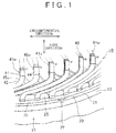
- FIG. 1 is a perspective view illustrating part, in a circumferential direction, of a rotary electric machine stator 10 in which a stator cuff support 20 according to the present embodiment is incorporated.
- the rotary electric machine stator 10 is just referred to as the stator 10.
- a supporter is called a stator cuff support.
- the stator 10 includes a stator core 12, a stator cuff support 20, and a stator coil 40.
- the stator coil 40 is configured as an assembly of a U-phase coil 41u, a V-phase coil 41v, and a W-phase coil 41w.
- the stator core 12 is formed by axially laminating a plurality of electromagnetic steel sheets, which are magnetic materials.
- the stator core 12 includes a toric yoke 13 and a plurality of stator teeth 14 ( FIG. 7 ) projecting radially inwardly from a plurality of circumferential positions on an inner peripheral surface of the yoke 13.
- the stator core 12 includes a plurality of slots 15 each formed between adjacent stator teeth 14
- the stator core 12 may be formed by pressing a resin binder and a magnetic powder.
- a “circumferential direction” indicates a circumferential direction around a central axis O (see FIG. 6 ) of the stator 10.
- a "radial direction” indicates a radial direction that is perpendicular to the central axis O
- an “axial direction” indicates an axial direction of the stator 10.
- FIG. 2 is a view illustrating part, in the circumferential direction, of the stator cuff support 20 that is taken out from FIG. 1 and viewed from an upper side.
- FIG. 3 is a perspective view of a part A in FIG. 2 when viewed from a diagonally upper side.
- FIG. 4 is a sectional view taken along a line B-B in FIG. 2 .
- FIG. 5 is an enlarged view of a part C in FIG. 3 .
- the stator cuff support 20 is used to assist a bending operation of conductor segments 42 (described later) constituting the stator coil 40.
- the stator cuff support 20 includes an outer annular portion 21, an inner annular portion 23, a plurality of cuff support teeth 25, and a positioning projection 28, which are formed integrally by injection molding of resin that is an insulation material.
- the outer annular portion 21 has a toric plate shape, and is placed to be put on one axial end surface (an upper end surface in FIG. 1 ) of the yoke 13 of the stator core 12 at the time of the use.
- the inner annular portion 23 is formed in a toric shape, and is placed inside the outer annular portion 21 so that a central axis of the inner annular portion 23 accords with that of the outer annular portion 21. As illustrated in FIG. 4 , an axial thickness T1 of the inner annular portion 23 is smaller than an axial thickness T2 of the outer annular portion 21 (T1 ⁇ T2).
- a radial length d1 of the inner annular portion 23 is smaller than a radial length d2 of the outer annular portion 21 (d1 ⁇ d2).
- the after-mentioned positioning projections 28 are formed at two places on a radially outer peripheral surface of the outer annular portion 21.
- the thickness indicates an axial length.
- the plurality of cuff support teeth 25 is placed radially between the outer annular portion 21 and the inner annular portion 23 so as to connect them. That part of a radially inner end portion of each of the cuff support teeth 25 which is placed on a side opposed to the stator core 12 extends to that side face of the inner annular portion 23 which is closer to a stator-core-12 side, and is connected to this side face.
- a bottom face on a stator-core-12 side is placed on each of the stator teeth 14 ( FIG. 7 ) of the stator core 12, and the bottom face has a width equivalent to each of the stator teeth 14 in the circumferential direction.
- a cuff support slot 26, which is a hole, is formed between adjacent cuff support teeth 25.
- an axial thickness T3 of each of the cuff support teeth 25 is larger than an axial thickness T2 of the outer annular portion 21 (T3 > T2). Bottom faces of the cuff support teeth 25 and the outer annular portion 21 are placed on a plane.
- Each of the cuff support teeth 25 is placed to be put on one axial end surface of a corresponding one of the plurality of stator teeth 14 ( FIG. 7 ) of the stator core 12 such that the each of the cuff support teeth 25 extends in the radial direction to cover the one axial end surface.
- Chamfers 25a each having an arc section are formed in both circumferential ends of the outer peripheral surface of an axially outer end (an upper end in FIGS. 3 to 5 ) of each of the cuff support teeth 25.
- the conductor segment 42 makes contact with the chamfer 25a of each of the cuff support teeth 25 so that the conductor segment 42 is bent, at the time of manufacturing the stator 10.
- the stator cuff support 20 configured as such regulates a position of a bent portion at the time of bending the conductor segment 42.
- the positioning projections 28 are formed so as to project radially outwardly, at two positions that are axially symmetric with their phases being different by 180 degrees, on a radially outer peripheral surface of the outer annular portion 21 of the stator cuff support 20, as illustrated in FIG. 6 .
- two positioning projections 28 are formed at two positions distanced from each other at a regular interval in the circumferential direction on the radially outer peripheral surface of the outer annular portion 21.
- a shape of the positioning projection 28 has a generally triangular mountain shape.
- an axial thickness T4 of the positioning projection 28 is smaller than the axial thickness T2 of the outer annular portion 21 (T4 ⁇ T2).
- the axial thickness T4 of the positioning projection 28 is not more than two-thirds of the axial thickness T2 of the outer annular portion 21, preferably not more than a half thereof.
- a bottom face of the positioning projection 28 is also placed on a plane as well as the bottom faces of the cuff support teeth 25 and the outer annular portion 21.
- a radially outer peripheral surface of the positioning projection 28 is smoothly continuous with the radially outer peripheral surface of the outer annular portion 21 via a curved-surface portion 29 having an arc section that is hollowed in a recessed shape.
- the curved-surface portion 29 has a curvature radius R.
- FIG. 6 is a schematic perspective view illustrating a state where the stator cuff support 20 is positioned and placed to be put on the axial end surface of the stator core by a jig.
- Each of the positioning projections 28 is used for positioning by engaging the each of the positioning projections 28 with a recessed portion 52 of a locking jig 50 at the time when the stator cuff support 20 is positioned and placed to be put on the one axial surface of the stator core 12.
- stator cuff support 20 is fixed to the stator core 12
- stator cuff support 20 is placed on an upper end surface of the stator core 12 in a state where the stator core 12 is supported by a support member (not shown) with an axial direction of the stator core 12 being set along an up-down direction as illustrated in FIG. 6 .
- two locking jigs 50 that are placed aside in advance radially outside the stator core 12 are moved radially inwardly from the radially outside.
- Each of the locking jigs 50 is provided as a part of a manufacturing apparatus for a rotary electric machine, and is also formed in a block shape.
- each of the locking jigs 50 a recessed portion 52 having a V-shaped section is formed on a facing surface to the outer peripheral surface of the stator cuff support 20.
- Each of the locking jigs 50 moves radially inwardly while the recessed portion 52 of the each of the locking jigs 50 engages with its corresponding positioning projection 28, and presses the outer peripheral surface of the stator cuff support 20 from the radially outside so as to sandwich the outer peripheral surface of the stator cuff support 20.
- the stator cuff support 20 is positioned and placed at a predetermined position. In this state, central axes of the stator cuff support 20 and the stator core 12 are aligned, and the stator cuff support 20 is positioned at a predetermined position in the circumferential direction.
- each of the locking jigs 50 is supported by a fixing part (not shown) that can move only in the radial direction of the stator core 12.
- Each of the locking jigs 50 is not limited to a block shape illustrated in FIG. 6 , provided that the each of the locking jigs 50 has a recessed portion that engages with the positioning projection 28, and configurations having various shapes including a pillar shape can be employed.
- a strength of the positioning projections 28 can be increased as described later and an occurrence of distortion at the time of the use can be restrained.
- FIG. 7 is a view corresponding to a D-D section of FIG. 2 in a state where the stator cuff support 20 is placed to be put on the axial end surface of the stator core 12 and the stator coil 40 is wound around the stator teeth 14.
- the stator cuff support 20 may be also placed on the other axial end surface of the stator core 12 as well as the one axial end surface thereof.
- Positioning projections 28 are also formed in the stator cuff support 20 placed on the other axial end surface of the stator core 12.
- the stator coil 40 is wound around the stator teeth 14 via the stator cuff support 20.
- the stator coil 40 is formed, in a state where a plurality of U-shaped conductor segments 42 is arranged in the radial direction, the plurality of U-shaped conductor segments 42 is placed on an outer side relative to the other axial end (a bottom end in FIG. 7 ) of the stator core 12.
- FIG. 7 illustrates a state after the conductor segments 42 are bent to be changed from the U-shape.
- Each of the conductor segments 42 is configured such that a conductor element wire is coated with an insulation coating and both ends of the conductor element wire are exposed from the insulation coating.
- Axial end portions 44 (see FIG. 1 ) extending in the axial direction are formed in tip ends of those parts of respective end portions of the leg portions of the conductor segment 42 which project upward from the one axial end surface of the stator core 12.
- the axial end portion 44 of the conductor segment 42 is put on an axial end portion 44 of another conductor segment 42 in the radial direction so as to be joined by welding.
- one winding of a coil is formed to step over a plurality of stator teeth 14.
- This process is repeated so that those parts of axial end portions 44 of a plurality of conductor segments 42 arranged in the radial direction which are put on top of one another in the radial direction are joined to each other, and hereby, a coil element as one unit coil is formed.
- coil elements placed to be wound at several places in the circumferential direction of the stator core 12 are connected to each other in an annular shape, thereby forming respective phase coils 41 u, 41 v, 41 w of U, V, W phases.
- FIG. 1 illustrates a case where a U-phase first connected coil element 45u configured such that a plurality of coil elements is connected in an annular shape, and a U-phase second connected coil element 46u configured such that another plurality of coil elements is connected in an annular shape are formed.
- One end of the U-phase first connected coil element 45u is connected to one end of the U-phase second connected coil element 46u so as to form the U-phase coil 41u.
- the U-phase second connected coil element 46u is inserted into a slot 15 (see FIG. 7 ) shifted by one slot from the U-phase first connected coil element 45u toward one side in the circumferential direction (a right side in FIG. 1 ).
- the V-phase coil 41v and the W-phase coil 41w are also formed in the same manner as the U-phase coil 41u.
- the U-phase coil 41u, the V-phase coil 41v, and the W-phase coil 41w are inserted into respective slots 15 shifted from each other in the circumferential direction of the stator core 12.
- a three-phase stator coil 40 wound around the stator teeth 14 of the stator core 12 by distributed winding is formed.
- stator coil 40 in a state where the stator coil 40 is wound around the stator teeth 14, the stator coil 40 is fixed to the stator core 12. At this time, by dropping varnish from an upper side of the stator core 12 and the stator coil 40, for example, the varnish is impregnated and solidified between the stator core 12 and the stator coil 40.
- the stator coil 40 is wound around the stator teeth 14 by distributed winding, but may be wound around the stator teeth 14 by concentrated winding.
- the positioning projection 28 may be formed only at one place of the radially outer peripheral surface of the stator cuff support 20, but from a viewpoint of increasing workability of a positioning operation, it is preferable to form the positioning projections 28 at two places or more on the outer peripheral surface of the stator cuff support 20.
- the positioning projections 28 may be formed at three places or more distanced from each other at regular intervals along an outer periphery on the outer peripheral surface of the outer annular portion 21.
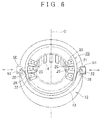
- FIG. 8 is a view corresponding to FIG. 5 and illustrates another example of the stator cuff support 20.
- the positioning projection 28 illustrated in FIG. 5 has a generally triangular mountain shape, but may be configured to have a shape with an arc section like a positioning projection 28 of FIG. 8 .
- the positioning projection 28 may be configured to have a shape other than the configurations illustrated in FIGS. 5 , 8 .
- the stator cuff support 20 has such a configuration in which the positioning projection 28 for positioning relative to the stator core 12 is provided in the outer annular portion 21, thereby making it possible to restrain an occurrence of distortion at the time of the use. More specifically, the positioning projection 28 is formed in a projecting manner on the outer peripheral surface of the outer annular portion 21, and the thickness T4 of the positioning projection 28 is smaller than the thickness T2 of the outer annular portion 21. Hereby, it is possible to restrain an occurrence of distortion at the time of the use of the stator cuff support 20. More specifically, the stator cuff support 20 is formed by injection molding of resin inside a die.
- a radial length of the part, in the circumferential direction, of the stator cuff support 20 becomes large inside the die. Because of this, when a temperature is changed inside the die from a high temperature to a low temperature, a degree of solidification of the resin due to cooling is different in the part in the circumferential direction from the other parts. This may cause a so-called sink mark in which the resin largely shrinks in the part in the circumferential direction.
- a circumferential length S1 ( FIG. 2 ) and a radial length d4 ( FIG. 4 ) of a part where the positioning projection 28 projects can be both increased relative to the outer peripheral surface of the outer annular portion 21. Further, a contact area between the locking jig 50 and the positioning projection 28 at an engagement portion can be increased.
- the positioning projection 28 is formed in the outer annular portion 21.
- the radial length d2 of the outer annular portion can be easily increased as compared with the radial length d1 of the inner annular portion 23.
- the outer peripheral surfaces of the positioning projection 28 and the outer annular portion 21 are smoothly continuous with each other via the curved-surface portion 29 having an arc section that is hollowed in a recessed shape, thereby making it possible to relax stress concentration on a connection portion between the outer annular portion 21 and the positioning projection 28.
- FIG. 9 illustrates one example of stress distribution in a peripheral portion of the positioning projection 28 in a case where a heat and cold cycle is repeated a predetermined number of times on the premise that the thickness of the positioning projection 28 is equivalent to the thickness of the outer annular portion 21 in the stator cuff support 20 of the embodiment.
- a shape of the positioning projection 28 of FIG. 9 viewed in the axial direction is the same as the shape of the positioning projection 28 illustrated in FIG. 5 .
- the "heat and cold cycle" indicates that a state where a temperature of the stator cuff support 20 is decreased to a predetermined low temperature and a state where the temperature of the stator cuff support 20 is increased to a predetermined high temperature are performed one by one sequentially.
- the stress becomes highest at a part indicated by a diagonal lattice, and the stress becomes lowest at a part indicated by dispersed circles.
- a part indicated as a sandy area in FIG. 9 shows that the stress is intermediate.
- a region where the stress of the stator cuff support 20 became higher could be reduced with the configuration of FIG. 9 . Further, a maximum value of the stress in the region where the stress became higher could be relatively lowered. Further, without rapid change of a shape of a recessed portion 30, which is a continuous portion between the outer peripheral surfaces of the positioning projection 28 and the outer annular portion 21, stress concentration on the recessed portion 30 could be relaxed. Also, similarly to the configuration in FIG. 9 , even in a case of the embodiment illustrated in FIGS. 1 to 8 , the shape of the outer annular portion 21 can be secured, and the outer peripheral surface of the outer annular portion 21 is not reduced by being scraped at part of the outer peripheral surface in the circumferential direction. Accordingly, a stress distribution of the embodiment illustrated in FIGS. 1 to 8 can be made equivalent to the stress distribution of the configuration of FIG. 9 or can be improved.
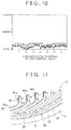
- FIG. 10 illustrates a relationship between a circumferential position of a cuff support tooth 25 and a height from a lowermost end to an upper end of the stator cuff support 20 at a corresponding circumferential position on the premise that the thickness of the positioning projection 28 is equivalent to the thickness of the outer annular portion 21 in the stator cuff support 20 of the embodiment.
- An example illustrated in FIG. 10 also shows a case where the heat and cold cycle is repeated a predetermined number of times, similarly to the configuration illustrated in FIG. 9 .
- the stator cuff support 20 includes 48 cuff support teeth 25 and positions of the cuff support teeth 25 are prescribed by numbers from 1 to 48. Further, the positioning projections 28 are formed at four positions distanced from each other at regular intervals in the circumferential direction of the outer annular portion 21.
- a horizontal axis of FIG. 10 indicates the numbers of the cuff support teeth 25 as circumferential positions of the cuff support teeth 25.
- a vertical axis of FIG. 10 indicates a height from the lowermost end of the stator cuff support 20 to the upper end thereof at the same circumferential position as a corresponding cuff support tooth 25 in a state where the stator cuff support 20 is placed on a horizontal plane.
- a height, on the top face, at a radial position deviated inwardly from a radially outer end of the cuff support tooth 25 just by a predetermined length is indicated by a blank square in FIG. 10 .
- a point P3 in FIG. 2 in the cuff support tooth 25, a height, on the top face, at a radial position deviated outwardly from a radial inner end of the inner annular portion 23 just by a predetermined length is almost the same as the case of the point P2 in FIG. 2 (the blank square in FIG. 10 ). From a simulation result of FIG. 10 , it was confirmed that the height from the lowermost end could be made small regardless of the radial position of the stator cuff support 20.
- the shape of the outer annular portion 21 can be secured, and the outer peripheral surface is not decreased by being scraped at part thereof in the circumferential direction.
- the height from the lowermost end can be also made small regardless of the radial position of the stator cuff support 20, similarly to the result shown in FIG. 10 .
- FIG. 11 is a view corresponding to FIG. 1 and illustrates a rotary electric machine stator 10 in which a stator cuff support 20 according to a comparative example is incorporated.
- FIG. 12 is a view of the stator cuff support 20 taken out from FIG. 11 and viewed from its upper side.
- a thickness of an outer annular portion 21 is increased at one position in a circumferential direction of the stator cuff support 20, so as to become the same as a thickness of a cuff support tooth 25 at the same position in the circumferential direction.
- a positioning recessed portion 31 is formed by forming a recessed portion having a V-shaped section on a radially outer face of that part of the outer annular portion 21 which has an increased thickness.
- the positioning recessed portion 31 also has a function to position the stator cuff support 20 relative to the stator core 12, similarly to the positioning projection 28 of the embodiment shown in FIGS. 1 to 6 and FIG. 8 .
- a positioning pin provided as a part of a manufacturing apparatus for a rotary electric machine is moved inwardly from a radially outside of the stator cuff support 20 so as to press the stator cuff support 20 from both sides while the positioning pin engages with the positioning recessed portion 31.
- the stator cuff support 20 is positioned relative to the stator core 12, so that alignment and positioning in the circumferential direction are performed.
- Other configurations in the comparative example are the same as in the embodiment of FIGS. 1 to 6 and FIG. 8 .
- FIG. 13 illustrates one example of a stress distribution in a peripheral portion of the positioning recessed portion 31 in a case where a heat and cold cycle is repeated a predetermined number of times in the stator cuff support 20 of the comparative example.
- meanings of parts indicated by a diagonal lattice, a sandy area, dispersed circles are the same as the case of FIG. 9 .
- a stress became highest in a vicinity of a deep end of the positioning recessed portion 31 in the comparative example.
- a maximum value of the stress in this part where the stress became highest was larger than the maximum value of the stress at the part indicated by the diagonal lattice in a case of the configuration of FIG. 9 .
- a thermal stress occurs due to repetition of the heat and cold cycle, so that a curve occurs in a bottom face of the stator cuff support 20 near the positioning recessed portion 31 and becomes breakable, thereby resulting in that durability may decrease.
- FIG. 9 From the comparison between FIG. 9 and FIG. 13 , in a case where the positioning recessed portion 31 is formed like the comparative example illustrated in FIG. 13 , a range of the part where the stress becomes high is increased and the maximum value of the stress becomes higher as compared with a case where the positioning projection 28 is formed like the configuration illustrated in FIG. 9 .
- a stress to be caused in the stator cuff support 20 can be lowered in comparison with the comparative example.
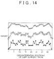
- FIG. 14 illustrates a relationship between a circumferential position of a cuff support tooth 25 and a height from a lowermost end to an upper end of the stator cuff support 20 at a corresponding circumferential position on the premise that the heat and cool cycle is repeated a predetermined number of times in the stator cuff support 20 of the comparative example.
- a height at a position of a point P1 in FIG. 12 is indicated by a black diamond shape.
- a height at a position of a point P2 in FIG. 12 is indicated by a blank square in FIG. 14 .
- a height at a position of a point P3 in FIG. 12 is indicated by a blank triangle in FIG. 14 .
- the other meanings in FIG. 14 are the same as in the case of FIG. 13 .
- Note that "25" at the circumferential position of the cuff support tooth 25 in FIG. 14 indicates a formation position of the positioning recessed portion 31.
Landscapes
- Engineering & Computer Science (AREA)
- Power Engineering (AREA)
- Manufacturing & Machinery (AREA)
- Iron Core Of Rotating Electric Machines (AREA)
- Insulation, Fastening Of Motor, Generator Windings (AREA)
Applications Claiming Priority (1)
| Application Number | Priority Date | Filing Date | Title |
|---|---|---|---|
| JP2014260352A JP2016123154A (ja) | 2014-12-24 | 2014-12-24 | ステータカフサ |
Publications (1)
| Publication Number | Publication Date |
|---|---|
| EP3038234A1 true EP3038234A1 (en) | 2016-06-29 |
Family
ID=54850244
Family Applications (1)
| Application Number | Title | Priority Date | Filing Date |
|---|---|---|---|
| EP15200703.5A Withdrawn EP3038234A1 (en) | 2014-12-24 | 2015-12-17 | Supporter for stator |
Country Status (5)
| Country | Link |
|---|---|
| US (1) | US20160190876A1 (zh) |
| EP (1) | EP3038234A1 (zh) |
| JP (1) | JP2016123154A (zh) |
| KR (1) | KR101758807B1 (zh) |
| CN (1) | CN105743240A (zh) |
Families Citing this family (3)
| Publication number | Priority date | Publication date | Assignee | Title |
|---|---|---|---|---|
| JP2018067996A (ja) * | 2016-10-18 | 2018-04-26 | トヨタ自動車株式会社 | 回転電機のステータの製造方法 |
| US10819182B2 (en) | 2017-01-09 | 2020-10-27 | Ge Aviation Systems Llc | Stator support for an electric machine |
| JP6725609B2 (ja) * | 2018-09-04 | 2020-07-22 | 本田技研工業株式会社 | ステータコアの位置決め固定方法及びその装置 |
Citations (4)
| Publication number | Priority date | Publication date | Assignee | Title |
|---|---|---|---|---|
| JP2005039992A (ja) * | 2003-06-24 | 2005-02-10 | Asmo Co Ltd | ブラシレスモータ及びパワーステアリング装置用モータ |
| JP2007312549A (ja) | 2006-05-19 | 2007-11-29 | Denso Corp | 回転電機の固定子及びその製造方法 |
| KR20120058765A (ko) * | 2010-11-30 | 2012-06-08 | 주식회사 아모텍 | 분할 코어형 스테이터, 그의 제조방법과 이를 이용한 비엘디씨 모터 |
| US20130169085A1 (en) * | 2011-12-28 | 2013-07-04 | Fujitsu General Limited | Electric motor |
Family Cites Families (10)
| Publication number | Priority date | Publication date | Assignee | Title |
|---|---|---|---|---|
| US1870813A (en) * | 1929-03-26 | 1932-08-09 | Westinghouse Electric & Mfg Co | Finger plate |
| US3593405A (en) * | 1969-09-05 | 1971-07-20 | Gen Electric | Apparatus for forming winding end turns |
| US5755023A (en) * | 1996-06-05 | 1998-05-26 | L.H. Carbide Corporation | Lamina stack with at least one lamina layer having a plurality of discrete segments and an apparatus and method for manufacturing said stack |
| WO2001029953A1 (en) * | 1999-10-21 | 2001-04-26 | Emerson Electric Co. | Shroud for covering a stator winding head |
| US6849982B2 (en) * | 2001-05-02 | 2005-02-01 | Newage International Limited | Toroidal electrical machine and an annular winding carrier therefor |
| JP4281458B2 (ja) * | 2003-08-07 | 2009-06-17 | トヨタ自動車株式会社 | カフサ開閉装置 |
| JP2008061312A (ja) * | 2006-08-29 | 2008-03-13 | Yaskawa Electric Corp | 固定子とこれを備えたモータ |
| JP5917109B2 (ja) * | 2011-11-29 | 2016-05-11 | アイチエレック株式会社 | 端部絶縁部材、固定子および回転機 |
| JP2014082804A (ja) * | 2012-10-12 | 2014-05-08 | Fanuc Ltd | 固定子および回転子を備えた電動機 |
| US9130439B2 (en) * | 2013-04-16 | 2015-09-08 | Remy Technologies, L.L.C. | Method of flaring stator windings |
-
2014
- 2014-12-24 JP JP2014260352A patent/JP2016123154A/ja active Pending
-
2015
- 2015-12-16 US US14/971,074 patent/US20160190876A1/en not_active Abandoned
- 2015-12-16 KR KR1020150179817A patent/KR101758807B1/ko active IP Right Grant
- 2015-12-17 EP EP15200703.5A patent/EP3038234A1/en not_active Withdrawn
- 2015-12-21 CN CN201510964098.7A patent/CN105743240A/zh active Pending
Patent Citations (4)
| Publication number | Priority date | Publication date | Assignee | Title |
|---|---|---|---|---|
| JP2005039992A (ja) * | 2003-06-24 | 2005-02-10 | Asmo Co Ltd | ブラシレスモータ及びパワーステアリング装置用モータ |
| JP2007312549A (ja) | 2006-05-19 | 2007-11-29 | Denso Corp | 回転電機の固定子及びその製造方法 |
| KR20120058765A (ko) * | 2010-11-30 | 2012-06-08 | 주식회사 아모텍 | 분할 코어형 스테이터, 그의 제조방법과 이를 이용한 비엘디씨 모터 |
| US20130169085A1 (en) * | 2011-12-28 | 2013-07-04 | Fujitsu General Limited | Electric motor |
Also Published As
| Publication number | Publication date |
|---|---|
| JP2016123154A (ja) | 2016-07-07 |
| CN105743240A (zh) | 2016-07-06 |
| US20160190876A1 (en) | 2016-06-30 |
| KR101758807B1 (ko) | 2017-07-17 |
| KR20160078253A (ko) | 2016-07-04 |
Similar Documents
| Publication | Publication Date | Title |
|---|---|---|
| EP3476021B1 (en) | Stator and motor having the same | |
| US9160217B2 (en) | Busbar unit and motor | |
| US9136746B2 (en) | Stator for electric rotating machine and method of manufacturing the same | |
| EP2983271B1 (en) | Insulated stator for rotary electric machine | |
| EP2827476B1 (en) | Stator and method for manufacturing stator | |
| US10476336B2 (en) | Stator assembly | |
| JP6299729B2 (ja) | 回転電機ステータ | |
| EP3211772A1 (en) | Stator production method and coil | |
| EP2833521A1 (en) | Stator | |
| JP5917109B2 (ja) | 端部絶縁部材、固定子および回転機 | |
| EP3145058B1 (en) | Stator assembling method and stator | |
| EP3038234A1 (en) | Supporter for stator | |
| JP5352979B2 (ja) | 回転電機の固定子及びその製造方法 | |
| JP6305620B2 (ja) | 回転電機の固定子および、回転電機の固定子の製造方法 | |
| US8225484B2 (en) | Method of manufacturing stator for electric rotating machine | |
| JP6554774B2 (ja) | ステータ巻線 | |
| JP2017073924A (ja) | 電動機用ステータ | |
| JP5496159B2 (ja) | 円筒型リニアモータ及び円筒型リニアモータの固定子コイルの巻装方法 | |
| JP2009071948A (ja) | 回転電機の固定子及びその製造方法 | |
| JP7371506B2 (ja) | 電機子の製造方法及び電機子 | |
| JP7463995B2 (ja) | 電機子及び電機子の製造方法 | |
| JP2019022380A (ja) | 巻線ガイド及び固定子 | |
| JP6632740B2 (ja) | 回転電機のステータとその製造方法 | |
| JP2007104863A (ja) | 外転型コンデンサ電動機の固定子 | |
| JP6045300B2 (ja) | ステータの製造方法 |
Legal Events
| Date | Code | Title | Description |
|---|---|---|---|
| PUAI | Public reference made under article 153(3) epc to a published international application that has entered the european phase |
Free format text: ORIGINAL CODE: 0009012 |
|
| 17P | Request for examination filed |
Effective date: 20151217 |
|
| AK | Designated contracting states |
Kind code of ref document: A1 Designated state(s): AL AT BE BG CH CY CZ DE DK EE ES FI FR GB GR HR HU IE IS IT LI LT LU LV MC MK MT NL NO PL PT RO RS SE SI SK SM TR |
|
| AX | Request for extension of the european patent |
Extension state: BA ME |
|
| STAA | Information on the status of an ep patent application or granted ep patent |
Free format text: STATUS: THE APPLICATION HAS BEEN WITHDRAWN |
|
| 18W | Application withdrawn |
Effective date: 20171108 |