EP3037355A1 - Verpackungsmaschine mit hygienischem pneumatikzylinder - Google Patents
Verpackungsmaschine mit hygienischem pneumatikzylinder Download PDFInfo
- Publication number
- EP3037355A1 EP3037355A1 EP15194850.2A EP15194850A EP3037355A1 EP 3037355 A1 EP3037355 A1 EP 3037355A1 EP 15194850 A EP15194850 A EP 15194850A EP 3037355 A1 EP3037355 A1 EP 3037355A1
- Authority
- EP
- European Patent Office
- Prior art keywords
- packaging machine
- cylinder body
- sensor
- machine according
- pneumatic cylinder
- Prior art date
- Legal status (The legal status is an assumption and is not a legal conclusion. Google has not performed a legal analysis and makes no representation as to the accuracy of the status listed.)
- Granted
Links
Images



Classifications
-
- F—MECHANICAL ENGINEERING; LIGHTING; HEATING; WEAPONS; BLASTING
- F15—FLUID-PRESSURE ACTUATORS; HYDRAULICS OR PNEUMATICS IN GENERAL
- F15B—SYSTEMS ACTING BY MEANS OF FLUIDS IN GENERAL; FLUID-PRESSURE ACTUATORS, e.g. SERVOMOTORS; DETAILS OF FLUID-PRESSURE SYSTEMS, NOT OTHERWISE PROVIDED FOR
- F15B15/00—Fluid-actuated devices for displacing a member from one position to another; Gearing associated therewith
- F15B15/20—Other details, e.g. assembly with regulating devices
- F15B15/28—Means for indicating the position, e.g. end of stroke
- F15B15/2892—Means for indicating the position, e.g. end of stroke characterised by the attachment means
-
- B—PERFORMING OPERATIONS; TRANSPORTING
- B65—CONVEYING; PACKING; STORING; HANDLING THIN OR FILAMENTARY MATERIAL
- B65B—MACHINES, APPARATUS OR DEVICES FOR, OR METHODS OF, PACKAGING ARTICLES OR MATERIALS; UNPACKING
- B65B65/00—Details peculiar to packaging machines and not otherwise provided for; Arrangements of such details
-
- B—PERFORMING OPERATIONS; TRANSPORTING
- B65—CONVEYING; PACKING; STORING; HANDLING THIN OR FILAMENTARY MATERIAL
- B65B—MACHINES, APPARATUS OR DEVICES FOR, OR METHODS OF, PACKAGING ARTICLES OR MATERIALS; UNPACKING
- B65B9/00—Enclosing successive articles, or quantities of material, e.g. liquids or semiliquids, in flat, folded, or tubular webs of flexible sheet material; Subdividing filled flexible tubes to form packages
- B65B9/02—Enclosing successive articles, or quantities of material between opposed webs
- B65B9/04—Enclosing successive articles, or quantities of material between opposed webs one or both webs being formed with pockets for the reception of the articles, or of the quantities of material
-
- F—MECHANICAL ENGINEERING; LIGHTING; HEATING; WEAPONS; BLASTING
- F15—FLUID-PRESSURE ACTUATORS; HYDRAULICS OR PNEUMATICS IN GENERAL
- F15B—SYSTEMS ACTING BY MEANS OF FLUIDS IN GENERAL; FLUID-PRESSURE ACTUATORS, e.g. SERVOMOTORS; DETAILS OF FLUID-PRESSURE SYSTEMS, NOT OTHERWISE PROVIDED FOR
- F15B15/00—Fluid-actuated devices for displacing a member from one position to another; Gearing associated therewith
- F15B15/08—Characterised by the construction of the motor unit
- F15B15/14—Characterised by the construction of the motor unit of the straight-cylinder type
- F15B15/1423—Component parts; Constructional details
- F15B15/1428—Cylinders
-
- F—MECHANICAL ENGINEERING; LIGHTING; HEATING; WEAPONS; BLASTING
- F15—FLUID-PRESSURE ACTUATORS; HYDRAULICS OR PNEUMATICS IN GENERAL
- F15B—SYSTEMS ACTING BY MEANS OF FLUIDS IN GENERAL; FLUID-PRESSURE ACTUATORS, e.g. SERVOMOTORS; DETAILS OF FLUID-PRESSURE SYSTEMS, NOT OTHERWISE PROVIDED FOR
- F15B15/00—Fluid-actuated devices for displacing a member from one position to another; Gearing associated therewith
- F15B15/20—Other details, e.g. assembly with regulating devices
- F15B15/28—Means for indicating the position, e.g. end of stroke
- F15B15/2807—Position switches, i.e. means for sensing of discrete positions only, e.g. limit switches
Definitions
- the invention relates to a packaging machine according to the preamble of claim 1.
- the pneumatic cylinder has integrated sensors and an integrated valve within its housing in order to improve the cleaning possibilities and to reduce the potential dirt traps such as lines in number.
- a disadvantage of this pneumatic cylinder is that the sensors can not be easily adjusted. Subsequent integration of one or more sensors for end position sensing is not possible.
- the WO 02/068828 A1 discloses a power cylinder with adjustable sensors, which are arranged in grooves adjustable on the housing.
- the sensors determine non-contact certain positions of the cylinder piston inside a cylinder body.
- the sensors are connected to a control integrated in the cylinder.
- the grooves, which are provided for the sensors, represent a hard-to-clean area on the working cylinder.
- the object of the present invention is to improve a packaging machine such as a thermoforming packaging machine, a tray sealing machine or a vacuum chamber machine in such a way that pneumatic cylinders provided at workstations are hygienic, ie easy to clean, and flexible with respect to the positionability of sensors.
- the packaging machine comprises at least one work station with a lifting drive, which comprises a pneumatic cylinder, wherein the pneumatic cylinder has a cylinder body, a piston rod and a piston whose position relative to the cylinder body is detected without contact by means of at least one sensor, wherein the sensor is provided outside of the cylinder body ,
- the packaging machine is characterized in that a separately manufactured from the cylinder body and inserted into the cylinder body mounting shell for the sensor in the outside of the cylinder body is provided, wherein the mounting shell has two longitudinal edges defining an upper plane, wherein a circumferential wall of the mounting shell has four side walls, each including an angle of less than 87 ° with the plane. So cleaning agents or water can easily and safely drain in most installation positions of the pneumatic cylinder in the workstation.
- the recess has a depth of at least 5 mm in order to position the sensor as close as possible to the piston of the piston rod moving in the cylinder body in order to detect the position of the piston without contact.
- two mounting shells are provided to detect or interrogate the position of both a largely retracted as well as a largely extended piston rod.
- the attachment shells are preferably provided on a common side surface of the cylinder body.
- the mounting shells are provided on two different side surfaces of the cylinder body in order to interrogate at least two positions in pneumatic cylinders with a short cylinder body can.
- the senor is adjustable relative to the fastening shell in the direction of movement of the piston rod in order not to be limited to the end positions of the piston or the piston rod.
- the senor is a proximity switch, preferably a cylindrical proximity switch, which can detect the piston of the piston rod without contact.
- the sensor can be configured, for example, as a capacitive or inductive proximity switch.
- the capacitance or the inductance of the sensor is influenced or disturbed when the piston is in the vicinity of the sensor. If the fault exceeds a predetermined threshold, this is detected by the sensor as an indication of a specific position of the piston and sent out as a position signal.
- the pneumatic cylinder has a cylinder body with four side surfaces, wherein the side surfaces with the exception of the attachment shells have a smooth surface in order to be easily cleaned.
- Smooth means that the Surface is free of grooves, recesses or projections, for example. Screw heads or the like.
- the angle between a side wall and the plane of the fastening shell is less than 75 °, preferably less than 60 °.
- FIG. 1 shows a packaging machine 1 in the form of a thermoforming packaging machine with multiple workstations such as a forming station 3, a sealing station 4 and a cutting station 7.
- a film web 2 is deep-drawn in the forming station 3 to form a trough 5 for receiving a product 6.
- a cover film 8 is applied airtight to the trough 5 filled with product 6.
- the still contiguous packaging 9 are cut apart and separated.
- Both the forming station 3 and the sealing station 4 and the cutting station 7 can have lifting drives 30 of different design, which comprise a pneumatic cylinder 10.
- the lifting movement does not have to be transmitted directly via a piston rod 11 of the pneumatic cylinder 10 to a tool unit of the workstation 3, 4, 7 to be lifted.
- gear mechanisms such as a toggle lever or the like may be interposed to increase the lifting force to cause a guide for the movement or to form several points of attack for the lifting force on the tool unit, for example on the mold base.
- the pneumatic cylinder 10 includes schematically illustrated sensors 12 for detecting the end position of the piston rod 11 or - by means of an adjustment of the sensors 12 - any position of the piston rod 11.
- the sensors 12, here specifically proximity switch are connected to a machine controller 13.
- the machine control 13 controls via lines 14, the movement of the piston and thus the piston rod 11 by means not shown in detail.
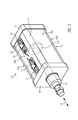
- Fig. 2 shows a perspective single view of the pneumatic cylinder 10 with the piston rod 11, with a piston 11 a and with the two sensors 12, which are arranged on the upper outer side A of the pneumatic cylinder 10.
- the piston rod 11 is in a direction of movement R, as in Fig. 2 shown as a double arrow, movable.
- the pneumatic cylinder 10 comprises a cylinder body 15, a first front closing end 16 and a second rear closing end 17.
- the cylinder body 15 has four side surfaces 18a, b, c, d.
- On the upwardly oriented side surface 18 b two mounting shells 20 are provided, in each of which a sensor 12 by means of a terminal block 21 can be fastened or clamped.
- the four side surfaces 18a, b, c, d and thus the outer surface of the cylinder body 15 are smooth.
- FIG. 3 shows an alternative embodiment in which the pneumatic cylinder 10 each having a mounting shell 20 on each of an adjacent side surface 18b and 18c.
- the mounting shells 20 are provided on two opposite sides 18b, 18d, namely at the top and bottom of the drawing in the drawing. This is particularly advantageous for cylinder bodies 15 with a short length.
- Fig. 4 shows the separately manufactured from the cylinder body 15 mounting shell 20 in a sectional view.
- the mounting shell 20 has a recess 22 and a circumferential wall 23, wherein the wall 23 itself in four side walls 23 a, b, c, d is divisible, wherein the non-visible through the section left side wall 23 d opposite the right side wall 23 b is arranged ,
- the side walls 23 a, b, c, d have a slope ⁇ of less than 87 °, here 75 ° with respect to a plane E, which is defined by the circumferential upper edge 24 at the top of the mounting shell 20.
- the two longitudinal edges 24 of the fastening shell 20 lie in the common plane E.
- the depression 22 has a depth T of, for example, 10 mm with respect to the upper edge 24 or the plane E, respectively.
- water or cleaning agent which has penetrated onto or into the fastening shell 20 during cleaning can independently run downwards out of the fastening shell 20 without residues remaining on the pneumatic cylinder 10, the pneumatic cylinder 10 not being in a relatively horizontal position with the fastening shells 20 on the upper side should be provided. Only in such an installation position could water remain in the recess of the fastening shell 20.
Landscapes
- Engineering & Computer Science (AREA)
- Mechanical Engineering (AREA)
- Physics & Mathematics (AREA)
- Fluid Mechanics (AREA)
- General Engineering & Computer Science (AREA)
- Package Closures (AREA)
- Actuator (AREA)
- Auxiliary Devices For And Details Of Packaging Control (AREA)
Abstract
Description
- Die Erfindung bezieht sich auf eine Verpackungsmaschine gemäß dem Oberbegriff des Anspruchs 1.
- Aus der
DE 10 2005 038 357 A1 ist eine Verpackungsmaschine mit einem hygienischen Pneumatikzylinder an einer Arbeitsstation bekannt. Der Pneumatikzylinder weist innerhalb seines Gehäuses integrierte Sensoren und ein integriertes Ventil auf, um die Reinigungsmöglichkeiten zu verbessern und potentielle Schmutzfänger wie beispielsweise Leitungen in ihrer Anzahl zu verringern. Nachteilig an diesem Pneumatikzylinder ist, dass die Sensoren nicht einfach verstellt werden können. Ein nachträgliches Integrieren von einem oder mehreren Sensoren zur Endlagenabfrage ist nicht möglich. - Die
WO 02/068828 A1 - Aufgabe der vorliegenden Erfindung ist es, eine Verpackungsmaschine wie eine Tiefziehverpackungsmaschine, eine Schalenverschließmaschine oder eine Vakuumkammermaschine dahingehend zu verbessern, dass an Arbeitsstationen vorgesehene Pneumatikzylinder hygienisch, das bedeutet leicht reinigbar, und flexibel bezüglich der Positionierbarkeit von Sensoren ausführbar sind.
- Diese Aufgabe wird gelöst durch eine Verpackungsmaschine mit den Merkmalen des Anspruchs 1. Vorteilhafte Weiterbildungen der Erfindung sind in den Unteransprüchen angegeben.
- Die erfindungsgemäße Verpackungsmaschine umfasst wenigstens eine Arbeitsstation mit einem Hubantrieb, der einen Pneumatikzylinder umfasst, wobei der Pneumatikzylinder einen Zylinderkörper, eine Kolbenstange und einen Kolben aufweist, dessen Stellung gegenüber dem Zylinderkörper mittels wenigstens eines Sensors berührungslos erfasst wird, wobei der Sensor außerhalb des Zylinderkörpers vorgesehen ist. Die Verpackungsmaschine zeichnet sich dadurch aus, dass eine separat vom Zylinderkörper gefertigte und in den Zylinderkörper eingesetzte Befestigungsschale für den Sensor in der Außenseite des Zylinderkörpers vorgesehen ist, wobei die Befestigungsschale zwei Längsränder aufweist, die eine obere Ebene definieren, wobei eine umlaufende Wandung der Befestigungsschale vier Seitenwände aufweist, die jeweils einen Winkel von weniger als 87° mit der Ebene einschließen. So können Reinigungsmittel oder Wasser in den meisten Einbaulagen des Pneumatikzylinders in der Arbeitsstation leicht und sicher ablaufen.
- Bevorzugt weist die Vertiefung eine Tiefe von wenigstens 5 mm auf, um den Sensor so nahe wie möglich an dem sich im Zylinderkörper bewegenden Kolben der Kolbenstange positionieren zu können, um die Position des Kolbens berührungslos zu erfassen.
- Vorzugsweise sind zwei Befestigungsschalen vorgesehen, um die Position sowohl einer weitestgehend eingefahrenen als auch einer weitestgehend ausgefahrenen Kolbenstange zu erfassen bzw. abzufragen.
- Dabei sind die Befestigungsschalen vorzugsweise an einer gemeinsamen Seitenfläche des Zylinderkörpers vorgesehen.
- In einer alternativen Ausführung sind die Befestigungsschalen an zwei unterschiedlichen Seitenflächen des Zylinderkörpers vorgesehen, um bei Pneumatikzylindern mit einem kurzen Zylinderkörper wenigstens zwei Positionen abfragen zu können.
- In einer besonders vorteilhaften Ausführung ist der Sensor relativ zur Befestigungsschale in Bewegungsrichtung der Kolbenstange verstellbar, um nicht auf die Endlagen des Kolbens bzw. der Kolbenstange beschränkt zu sein.
- Vorzugsweise ist der Sensor ein Näherungsschalter, bevorzugt ein zylinderförmiger Näherungsschalter, der berührungslos den Kolben der Kolbenstange detektieren kann. Zu diesem Zweck kann der Sensor beispielsweise als kapazitiver oder induktiver Näherungsschalter konfiguriert sein. Dabei wird die Kapazität bzw. die Induktivität des Sensors beeinflusst oder gestört, wenn sich der Kolben in der Nähe des Sensors befindet. Überschreitet die Störung eine vorgegebene Schwelle, wird dies vom Sensor als Hinweis auf eine bestimmte Position des Kolbens erfasst und als Positionssignal ausgesendet.
- Bevorzugt weist der Pneumatikzylinder einen Zylinderkörper mit vier Seitenflächen auf, wobei die Seitenflächen mit Ausnahme der Befestigungsschalen eine glatte Oberfläche aufweisen, um leicht reinigbar zu sein. Glatt bedeutet, dass die Oberfläche frei ist von Nuten, Vertiefungen oder Vorsprüngen bspw. von Schraubenköpfen oder Ähnlichem.
- Bevorzugt beträgt der Winkel zwischen einer Seitenwand und der Ebene der Befestigungsschale weniger als 75°, vorzugsweise weniger als 60°.
- Im Folgenden wird ein vorteilhaftes Ausführungsbeispiel der Erfindung anhand einer Zeichnung näher erläutert. Im Einzelnen zeigen:
- Fig. 1
- eine schematische Darstellung einer erfindungsgemäße Verpackungsmaschine in der Seitenansicht,
- Fig. 2
- eine schematische perspektivische Darstellung eines Pneumatikzylinders in einer ersten Ausführung,
- Fig. 3
- einen Pneumatikzylinder in einer zweiten Ausführung und
- Fig. 4
- eine Schnittansicht der Befestigungsschale.
- Gleiche Komponenten sind in den Figuren durchgängig mit gleichen Bezugszeichen versehen.
-
Figur 1 zeigt eine Verpackungsmaschine 1 in Form einer Tiefziehverpackungsmaschine mit mehreren Arbeitsstationen wie einer Formstation 3, einer Versiegelungsstation 4 und einer Schneidstation 7. Eine Folienbahn 2 wird in der Formstation 3 unter Ausbildung einer Mulde 5 zur Aufnahme eines Produkts 6 tiefgezogen. In der Versiegelungsstation 4 wird eine Deckelfolie 8 auf die mit Produkt 6 gefüllte Mulde 5 luftdicht aufgebracht. In der darauf folgenden Schneidstation 7 werden die noch zusammenhängenden Verpackungen 9 auseinander geschnitten und vereinzelt. - Sowohl die Formstation 3 als auch die Versiegelungsstation 4 und die Schneidstation 7 können Hubantriebe 30 unterschiedlicher Bauform aufweisen, die einen Pneumatikzylinder 10 umfassen. Die Hubbewegung muss dabei nicht unmittelbar über eine Kolbenstange 11 des Pneumatikzylinders 10 auf eine anzuhebende Werkzeugeinheit der Arbeitsstation 3, 4, 7 übertragen werden. Je nach Anwendungsfall können Getriebemechanismen wie ein Kniehebelhubwerk oder dergleichen zwischengeschaltet sein, um die Hubkraft zu verstärken, um eine Führung für die Bewegung zu bewirken oder um mehrere Angriffspunkte für die Hubkraft an der Werkzeugeinheit, zum Beispiel am Formwerkzeugunterteil, auszubilden. Weiterhin umfasst der Pneumatikzylinder 10 schematisch dargestellte Sensoren 12 zur Erfassung der Endlage der Kolbenstange 11 oder - mittels einer Verstellmöglichkeit der Sensoren 12 - einer beliebigen Position der Kolbenstange 11. Die Sensoren 12, hier konkret Näherungsschalter, sind mit einer Maschinensteuerung 13 verbunden. Die Maschinensteuerung 13 steuert über Leitungen 14 die Bewegung des Kolbens und damit der Kolbenstange 11 mittels nicht näher dargestellter Ventile.
-
Fig. 2 zeigt eine perspektivische Einzelansicht des Pneumatikzylinders 10 mit der Kolbenstange 11, mit einem Kolben 11a und mit den zwei Sensoren 12, die an der oben liegenden Außenseite A des Pneumatikzylinders 10 angeordnet sind. Die Kolbenstange 11 ist in einer Bewegungsrichtung R, wie in derFig. 2 als Doppelpfeil dargestellt, bewegbar. Der Pneumatikzylinder 10 umfasst einen Zylinderkörper 15, ein erstes vorderes Verschließende 16 und ein zweites hinteres Verschließende 17. Der Zylinderkörper 15 weist vier Seitenflächen 18a, b, c, d auf. Auf der nach oben ausgerichteten Seitenfläche 18b sind zwei Befestigungsschalen 20 vorgesehen, in der jeweils ein Sensor 12 mittels einer Klemmleiste 21 befestigbar bzw. klemmbar ist. Die vier Seitenflächen 18a, b, c, d und somit die Außenfläche des Zylinderkörpers 15 sind glatt ausgeführt. -
Fig. 3 zeigt eine alternative Ausführungsform, bei der der Pneumatikzylinder 10 jeweils eine Befestigungsschale 20 an jeweils einer benachbarten Seitenfläche 18b und 18c aufweist. Unter dieser Ausführungsform ist auch eine nicht näher dargestellte Variante erfasst, bei der die Befestigungsschalen 20 an zwei gegenüberliegenden Seiten 18b, 18d, nämlich an der in der Zeichnung oben und unten liegenden Seite, vorgesehen sind. Dies ist vor allem bei Zylinderkörpern 15 mit einer geringen Länge vorteilhaft. -
Fig. 4 zeigt die separat vom Zylinderkörper 15 gefertigte Befestigungsschale 20 in einer Schnittdarstellung. Die Befestigungsschale 20 weist eine Vertiefung 22 und eine umlaufende Wandung 23 auf, wobei die Wandung 23 selbst in vier Seitenwände 23 a, b, c, d aufteilbar ist, wobei die durch den Schnitt nicht sichtbare linke Seitenwand 23d gegenüber der rechten Seitenwand 23b angeordnet ist. Die Seitenwände 23 a, b, c, d weisen eine Schräge β von weniger als 87°, hier von 75° gegenüber einer Ebene E auf, die durch den umlaufenden oberen Rand 24 an der Oberseite der Befestigungsschale 20 definiert wird. Mit anderen Worten liegen die beiden Längsränder 24 der Befestigungschale 20 in der gemeinsamen Ebene E. - Die Vertiefung 22 weist gegenüber dem oberen Rand 24 bzw. der Ebene E eine Tiefe T von beispielsweise 10mm auf. Dabei kann während der Reinigung auf oder in die Befestigungsschale 20 eingedrungenes Wasser oder Reinigungsmittel selbstständig nach unten aus der Befestigungsschale 20 ablaufen, ohne dass Rückstände am Pneumatikzylinder 10 verbleiben, wobei der Pneumatikzylinder 10 dabei nicht in einer relativ horizontalen Lage mit den Befestigungsschalen 20 an der Oberseite vorgesehen sein sollte. Lediglich in einer solchen Einbaulage könnte Wasser in der Vertiefung der Befestigungsschale 20 verbleiben.
Claims (9)
- Verpackungsmaschine (1), umfassend wenigstens eine Arbeitsstation (3, 4, 7) mit einem Hubantrieb (30), der einen Pneumatikzylinder (10) umfasst, wobei der Pneumatikzylinder (10) einen Zylinderkörper (15), eine Kolbenstange (11) und einen Kolben (11a) aufweist, dessen Stellung gegenüber dem Zylinderkörper (15) mittels wenigstens eines Sensors (12) berührungslos erfasst wird, wobei der Sensor (12) außerhalb des Zylinderkörpers (15) vorgesehen ist, dadurch gekennzeichnet, dass als eine separat gefertigte und in den Zylinderkörper (15) eingesetzte Befestigungsschale (20) für den Sensor (12) in der Außenseite (A) des Zylinderkörpers (15) vorgesehen ist, wobei die Befestigungsschale (20) zwei Längsränder (24) aufweist, die eine Ebene (E) definieren, wobei eine umlaufende Wandung (23) der Befestigungsschale (20) vier Seitenwände (23 a, b, c, d) aufweist, die jeweils einen Winkel (β) von weniger als 87° mit der Ebene (E) einschließen.
- Verpackungsmaschine nach Anspruch 1, dadurch gekennzeichnet, dass die Vertiefung (22) eine maximale Tiefe (T) in Bezug auf die Ebne (E) von wenigstens 5 mm aufweist.
- Verpackungsmaschine nach einem der vorangehenden Ansprüche, dadurch gekennzeichnet, dass zwei Befestigungsschalen (20) vorgesehen sind.
- Verpackungsmaschine nach Anspruch 3, dadurch gekennzeichnet, dass die Befestigungsschalen (20) an einer gemeinsamen Seitenfläche (18a, b, c, d) des Zylinderkörpers (15) vorgesehen sind.
- Verpackungsmaschine nach Anspruch 3, dadurch gekennzeichnet, dass die Befestigungsschalen (20) an zwei unterschiedlichen Seitenflächen (18a, b, c, d) des Zylinderkörpers (15) vorgesehen sind.
- Verpackungsmaschine nach einem der vorangehenden Ansprüche, dadurch gekennzeichnet, dass der Sensor (12) relativ zur Befestigungsschale (20) in Bewegungsrichtung (R) der Kolbenstange (11) verstellbar ist.
- Verpackungsmaschine nach einem der vorangehenden Ansprüche, dadurch gekennzeichnet, dass der Sensor (12) ein Näherungsschalter ist.
- Verpackungsmaschine nach einem der vorangehenden Ansprüche, dadurch gekennzeichnet, dass der Pneumatikzylinder (10) einen Zylinderkörper (15) mit vier Seitenflächen (18a, b, c, d) aufweist, wobei die Seitenflächen (18a, b, c, d) mit Ausnahme der Befestigungsschalen (20) eine glatte Oberfläche aufweisen.
- Verpackungsmaschine nach einem der vorangehenden Ansprüche, dadurch gekennzeichnet, dass der Winkel (β) maximal 75°, vorzugsweise maximal 60°, beträgt.
Applications Claiming Priority (1)
| Application Number | Priority Date | Filing Date | Title |
|---|---|---|---|
| DE102014226830.3A DE102014226830B4 (de) | 2014-12-22 | 2014-12-22 | Verpackungsmaschine mit hygienischem Pneumatikzylinder |
Publications (2)
| Publication Number | Publication Date |
|---|---|
| EP3037355A1 true EP3037355A1 (de) | 2016-06-29 |
| EP3037355B1 EP3037355B1 (de) | 2017-09-20 |
Family
ID=54545015
Family Applications (1)
| Application Number | Title | Priority Date | Filing Date |
|---|---|---|---|
| EP15194850.2A Not-in-force EP3037355B1 (de) | 2014-12-22 | 2015-11-17 | Verpackungsmaschine mit hygienischem pneumatikzylinder |
Country Status (4)
| Country | Link |
|---|---|
| US (1) | US20160177983A1 (de) |
| EP (1) | EP3037355B1 (de) |
| DE (1) | DE102014226830B4 (de) |
| ES (1) | ES2651906T3 (de) |
Families Citing this family (3)
| Publication number | Priority date | Publication date | Assignee | Title |
|---|---|---|---|---|
| WO2019219966A1 (de) * | 2018-05-18 | 2019-11-21 | Gea Food Solutions Germany Gmbh | Abrollen einer folienrolle in einer verpackungsmaschine |
| DE102019217178A1 (de) * | 2019-11-07 | 2021-05-12 | Max Aicher Gmbh & Co. Kg | Abschirmeinheit zur abgeschirmten Anordnung eines Sensors, Sensoranordnung mit einer derartigen Abschirmeinheit und Behälter |
| CN112499279B (zh) * | 2020-11-12 | 2023-01-24 | 临沂金悦环保科技有限公司 | 一种料盘自动分离输送装置 |
Citations (5)
| Publication number | Priority date | Publication date | Assignee | Title |
|---|---|---|---|---|
| GB2230385A (en) * | 1989-04-08 | 1990-10-17 | Festo Kg | Control devices |
| US20020014128A1 (en) * | 2000-08-04 | 2002-02-07 | Balluff Gmbh | Sensor assembly |
| WO2002068828A1 (de) | 2001-02-22 | 2002-09-06 | Festo Ag & Co | Arbeitszylinder |
| DE102005038357A1 (de) | 2005-08-11 | 2007-02-15 | Multivac Sepp Haggenmüller Gmbh & Co. Kg | Verpackungsmaschine mit wenigstens einem Pneumatikantrieb |
| DE112011104473T5 (de) * | 2010-12-21 | 2013-09-19 | Smc Corporation | Positionserfassungsvorrichtung für Fluiddruckzylinder |
Family Cites Families (7)
| Publication number | Priority date | Publication date | Assignee | Title |
|---|---|---|---|---|
| DE29816156U1 (de) * | 1998-09-09 | 1998-11-26 | Festo AG & Co, 73734 Esslingen | Linearantrieb |
| JP4496423B2 (ja) * | 2001-01-26 | 2010-07-07 | Smc株式会社 | 位置検出センサの取付構造 |
| DE10152178C2 (de) * | 2001-04-30 | 2003-04-17 | Rexroth Mecman Gmbh | Druckmittelzylinder mit einem verschiebbaren Sensor zur Detektion der Kolbenstellung |
| DE10210636C1 (de) * | 2002-03-11 | 2003-05-22 | Imi Norgren Gmbh | Fluidbetätigter Arbeitszylinder |
| DE102007029628B3 (de) * | 2007-06-26 | 2009-01-15 | Robert Bosch Gmbh | Pneumatikzylinder mit einem Zylindergehäuse aus stranggepresstem Metall |
| JP5004048B2 (ja) * | 2007-07-03 | 2012-08-22 | Smc株式会社 | シリンダ装置 |
| JP2009030674A (ja) * | 2007-07-25 | 2009-02-12 | Smc Corp | 位置検出センサの取付機構 |
-
2014
- 2014-12-22 DE DE102014226830.3A patent/DE102014226830B4/de not_active Expired - Fee Related
-
2015
- 2015-11-17 ES ES15194850.2T patent/ES2651906T3/es active Active
- 2015-11-17 EP EP15194850.2A patent/EP3037355B1/de not_active Not-in-force
- 2015-12-08 US US14/962,828 patent/US20160177983A1/en not_active Abandoned
Patent Citations (5)
| Publication number | Priority date | Publication date | Assignee | Title |
|---|---|---|---|---|
| GB2230385A (en) * | 1989-04-08 | 1990-10-17 | Festo Kg | Control devices |
| US20020014128A1 (en) * | 2000-08-04 | 2002-02-07 | Balluff Gmbh | Sensor assembly |
| WO2002068828A1 (de) | 2001-02-22 | 2002-09-06 | Festo Ag & Co | Arbeitszylinder |
| DE102005038357A1 (de) | 2005-08-11 | 2007-02-15 | Multivac Sepp Haggenmüller Gmbh & Co. Kg | Verpackungsmaschine mit wenigstens einem Pneumatikantrieb |
| DE112011104473T5 (de) * | 2010-12-21 | 2013-09-19 | Smc Corporation | Positionserfassungsvorrichtung für Fluiddruckzylinder |
Also Published As
| Publication number | Publication date |
|---|---|
| DE102014226830B4 (de) | 2016-11-24 |
| US20160177983A1 (en) | 2016-06-23 |
| DE102014226830A1 (de) | 2016-06-23 |
| EP3037355B1 (de) | 2017-09-20 |
| ES2651906T3 (es) | 2018-01-30 |
Similar Documents
| Publication | Publication Date | Title |
|---|---|---|
| EP0868965B1 (de) | Schlitten-Antriebsvorrichtung | |
| DE3903134C5 (de) | Stanzpresse | |
| DE102015210191B4 (de) | Fahrzeugstossfängeraufbau mit Fussgängerkollisionserfassungssensor | |
| DE69504445T2 (de) | Linearantrieb | |
| DE69506778T3 (de) | Antriebsgerät mit Schlittentisch | |
| EP3037355B1 (de) | Verpackungsmaschine mit hygienischem pneumatikzylinder | |
| DE3605505A1 (de) | Stossschutz-sicherheitseinrichtung fuer roboter | |
| EP1120574A1 (de) | Ventilanordnung | |
| DE102011011255B4 (de) | Greifeinrichtung | |
| EP3001159B1 (de) | Höhenverstellbare Fussanordnung | |
| EP2890243A1 (de) | Fördervorrichtung für artikel der fisch- und fleischverarbeitenden industrie | |
| EP3281893A1 (de) | Mehrfachsauggreifer | |
| EP2848398A1 (de) | Vorrichtung und Verfahren zum Verhindern des Bruchs eines Werkzeug beim Feinschneiden und/oder Umformen eines Werkstücks | |
| EP3000641B1 (de) | Straßenfertiger mit Bedienmodul und Verfahren zum Aufrufen einer Bedienfunktion | |
| DE4333860A1 (de) | Anlage zur Luftverteilung an wenigstens einen zu einer mit hoher Geschwindigkeit arbeitenden Maschine gehörenden Saugnapf | |
| DE3619341C2 (de) | Reinigungseinrichtung mit Antriebsmotor für eine ebene Sichtscheibe einer insbesondere öffenbaren Schutzabdeckung einer Werkzeugmaschine | |
| EP4142986B1 (de) | Sauggreifer und unterdruckhandhabungsanlage | |
| EP2328419A1 (de) | Vorrichtung und verfahren zum bearbeiten von fleisch, insbesondere fisch | |
| DE10140315A1 (de) | Greifer zum Haltern und Bewegen von Hohlkörpern | |
| DE102022111608A1 (de) | Bodenreinigungsmaschine und Verfahren zum Betrieb einer Bodenreinigungsmaschine | |
| DE102019120069B4 (de) | Anschlagmodul | |
| DE29819265U1 (de) | Linearführung | |
| EP2301329A1 (de) | Tränktrog | |
| EP3115304B1 (de) | Vakuumiergerät mit schweissbalkenabdeckung | |
| DE102005063327A1 (de) | Vorrichtung zum Trennen eines plastischen Tonstranges, mit einer allseitig wirksamen Kerbvorrichtung |
Legal Events
| Date | Code | Title | Description |
|---|---|---|---|
| PUAI | Public reference made under article 153(3) epc to a published international application that has entered the european phase |
Free format text: ORIGINAL CODE: 0009012 |
|
| AK | Designated contracting states |
Kind code of ref document: A1 Designated state(s): AL AT BE BG CH CY CZ DE DK EE ES FI FR GB GR HR HU IE IS IT LI LT LU LV MC MK MT NL NO PL PT RO RS SE SI SK SM TR |
|
| AX | Request for extension of the european patent |
Extension state: BA ME |
|
| 17P | Request for examination filed |
Effective date: 20161205 |
|
| RBV | Designated contracting states (corrected) |
Designated state(s): AL AT BE BG CH CY CZ DE DK EE ES FI FR GB GR HR HU IE IS IT LI LT LU LV MC MK MT NL NO PL PT RO RS SE SI SK SM TR |
|
| GRAP | Despatch of communication of intention to grant a patent |
Free format text: ORIGINAL CODE: EPIDOSNIGR1 |
|
| RIC1 | Information provided on ipc code assigned before grant |
Ipc: B65B 9/10 20060101ALI20170313BHEP Ipc: B65B 65/00 20060101ALI20170313BHEP Ipc: F15B 15/14 20060101ALI20170313BHEP Ipc: B65B 9/04 20060101AFI20170313BHEP Ipc: F15B 15/28 20060101ALI20170313BHEP |
|
| INTG | Intention to grant announced |
Effective date: 20170330 |
|
| GRAS | Grant fee paid |
Free format text: ORIGINAL CODE: EPIDOSNIGR3 |
|
| GRAA | (expected) grant |
Free format text: ORIGINAL CODE: 0009210 |
|
| AK | Designated contracting states |
Kind code of ref document: B1 Designated state(s): AL AT BE BG CH CY CZ DE DK EE ES FI FR GB GR HR HU IE IS IT LI LT LU LV MC MK MT NL NO PL PT RO RS SE SI SK SM TR |
|
| REG | Reference to a national code |
Ref country code: GB Ref legal event code: FG4D Free format text: NOT ENGLISH |
|
| REG | Reference to a national code |
Ref country code: CH Ref legal event code: EP |
|
| REG | Reference to a national code |
Ref country code: AT Ref legal event code: REF Ref document number: 929923 Country of ref document: AT Kind code of ref document: T Effective date: 20171015 |
|
| REG | Reference to a national code |
Ref country code: IE Ref legal event code: FG4D Free format text: LANGUAGE OF EP DOCUMENT: GERMAN |
|
| REG | Reference to a national code |
Ref country code: DE Ref legal event code: R096 Ref document number: 502015001942 Country of ref document: DE |
|
| REG | Reference to a national code |
Ref country code: FR Ref legal event code: PLFP Year of fee payment: 3 |
|
| REG | Reference to a national code |
Ref country code: NL Ref legal event code: MP Effective date: 20170920 |
|
| REG | Reference to a national code |
Ref country code: ES Ref legal event code: FG2A Ref document number: 2651906 Country of ref document: ES Kind code of ref document: T3 Effective date: 20180130 |
|
| PG25 | Lapsed in a contracting state [announced via postgrant information from national office to epo] |
Ref country code: HR Free format text: LAPSE BECAUSE OF FAILURE TO SUBMIT A TRANSLATION OF THE DESCRIPTION OR TO PAY THE FEE WITHIN THE PRESCRIBED TIME-LIMIT Effective date: 20170920 Ref country code: LT Free format text: LAPSE BECAUSE OF FAILURE TO SUBMIT A TRANSLATION OF THE DESCRIPTION OR TO PAY THE FEE WITHIN THE PRESCRIBED TIME-LIMIT Effective date: 20170920 Ref country code: FI Free format text: LAPSE BECAUSE OF FAILURE TO SUBMIT A TRANSLATION OF THE DESCRIPTION OR TO PAY THE FEE WITHIN THE PRESCRIBED TIME-LIMIT Effective date: 20170920 Ref country code: NO Free format text: LAPSE BECAUSE OF FAILURE TO SUBMIT A TRANSLATION OF THE DESCRIPTION OR TO PAY THE FEE WITHIN THE PRESCRIBED TIME-LIMIT Effective date: 20171220 Ref country code: SE Free format text: LAPSE BECAUSE OF FAILURE TO SUBMIT A TRANSLATION OF THE DESCRIPTION OR TO PAY THE FEE WITHIN THE PRESCRIBED TIME-LIMIT Effective date: 20170920 |
|
| REG | Reference to a national code |
Ref country code: LT Ref legal event code: MG4D |
|
| PG25 | Lapsed in a contracting state [announced via postgrant information from national office to epo] |
Ref country code: RS Free format text: LAPSE BECAUSE OF FAILURE TO SUBMIT A TRANSLATION OF THE DESCRIPTION OR TO PAY THE FEE WITHIN THE PRESCRIBED TIME-LIMIT Effective date: 20170920 Ref country code: LV Free format text: LAPSE BECAUSE OF FAILURE TO SUBMIT A TRANSLATION OF THE DESCRIPTION OR TO PAY THE FEE WITHIN THE PRESCRIBED TIME-LIMIT Effective date: 20170920 Ref country code: BG Free format text: LAPSE BECAUSE OF FAILURE TO SUBMIT A TRANSLATION OF THE DESCRIPTION OR TO PAY THE FEE WITHIN THE PRESCRIBED TIME-LIMIT Effective date: 20171220 |
|
| PG25 | Lapsed in a contracting state [announced via postgrant information from national office to epo] |
Ref country code: NL Free format text: LAPSE BECAUSE OF FAILURE TO SUBMIT A TRANSLATION OF THE DESCRIPTION OR TO PAY THE FEE WITHIN THE PRESCRIBED TIME-LIMIT Effective date: 20170920 |
|
| PG25 | Lapsed in a contracting state [announced via postgrant information from national office to epo] |
Ref country code: RO Free format text: LAPSE BECAUSE OF FAILURE TO SUBMIT A TRANSLATION OF THE DESCRIPTION OR TO PAY THE FEE WITHIN THE PRESCRIBED TIME-LIMIT Effective date: 20170920 Ref country code: PL Free format text: LAPSE BECAUSE OF FAILURE TO SUBMIT A TRANSLATION OF THE DESCRIPTION OR TO PAY THE FEE WITHIN THE PRESCRIBED TIME-LIMIT Effective date: 20170920 Ref country code: CZ Free format text: LAPSE BECAUSE OF FAILURE TO SUBMIT A TRANSLATION OF THE DESCRIPTION OR TO PAY THE FEE WITHIN THE PRESCRIBED TIME-LIMIT Effective date: 20170920 |
|
| PG25 | Lapsed in a contracting state [announced via postgrant information from national office to epo] |
Ref country code: SM Free format text: LAPSE BECAUSE OF FAILURE TO SUBMIT A TRANSLATION OF THE DESCRIPTION OR TO PAY THE FEE WITHIN THE PRESCRIBED TIME-LIMIT Effective date: 20170920 Ref country code: SK Free format text: LAPSE BECAUSE OF FAILURE TO SUBMIT A TRANSLATION OF THE DESCRIPTION OR TO PAY THE FEE WITHIN THE PRESCRIBED TIME-LIMIT Effective date: 20170920 Ref country code: EE Free format text: LAPSE BECAUSE OF FAILURE TO SUBMIT A TRANSLATION OF THE DESCRIPTION OR TO PAY THE FEE WITHIN THE PRESCRIBED TIME-LIMIT Effective date: 20170920 Ref country code: IS Free format text: LAPSE BECAUSE OF FAILURE TO SUBMIT A TRANSLATION OF THE DESCRIPTION OR TO PAY THE FEE WITHIN THE PRESCRIBED TIME-LIMIT Effective date: 20180120 |
|
| REG | Reference to a national code |
Ref country code: DE Ref legal event code: R097 Ref document number: 502015001942 Country of ref document: DE |
|
| PG25 | Lapsed in a contracting state [announced via postgrant information from national office to epo] |
Ref country code: MC Free format text: LAPSE BECAUSE OF FAILURE TO SUBMIT A TRANSLATION OF THE DESCRIPTION OR TO PAY THE FEE WITHIN THE PRESCRIBED TIME-LIMIT Effective date: 20170920 |
|
| PLBE | No opposition filed within time limit |
Free format text: ORIGINAL CODE: 0009261 |
|
| STAA | Information on the status of an ep patent application or granted ep patent |
Free format text: STATUS: NO OPPOSITION FILED WITHIN TIME LIMIT |
|
| PG25 | Lapsed in a contracting state [announced via postgrant information from national office to epo] |
Ref country code: DK Free format text: LAPSE BECAUSE OF FAILURE TO SUBMIT A TRANSLATION OF THE DESCRIPTION OR TO PAY THE FEE WITHIN THE PRESCRIBED TIME-LIMIT Effective date: 20170920 |
|
| 26N | No opposition filed |
Effective date: 20180621 |
|
| PG25 | Lapsed in a contracting state [announced via postgrant information from national office to epo] |
Ref country code: LU Free format text: LAPSE BECAUSE OF NON-PAYMENT OF DUE FEES Effective date: 20171117 |
|
| REG | Reference to a national code |
Ref country code: BE Ref legal event code: MM Effective date: 20171130 |
|
| REG | Reference to a national code |
Ref country code: IE Ref legal event code: MM4A |
|
| PG25 | Lapsed in a contracting state [announced via postgrant information from national office to epo] |
Ref country code: MT Free format text: LAPSE BECAUSE OF FAILURE TO SUBMIT A TRANSLATION OF THE DESCRIPTION OR TO PAY THE FEE WITHIN THE PRESCRIBED TIME-LIMIT Effective date: 20170920 |
|
| PG25 | Lapsed in a contracting state [announced via postgrant information from national office to epo] |
Ref country code: IE Free format text: LAPSE BECAUSE OF NON-PAYMENT OF DUE FEES Effective date: 20171117 |
|
| PG25 | Lapsed in a contracting state [announced via postgrant information from national office to epo] |
Ref country code: SI Free format text: LAPSE BECAUSE OF FAILURE TO SUBMIT A TRANSLATION OF THE DESCRIPTION OR TO PAY THE FEE WITHIN THE PRESCRIBED TIME-LIMIT Effective date: 20170920 Ref country code: BE Free format text: LAPSE BECAUSE OF NON-PAYMENT OF DUE FEES Effective date: 20171130 |
|
| PG25 | Lapsed in a contracting state [announced via postgrant information from national office to epo] |
Ref country code: HU Free format text: LAPSE BECAUSE OF FAILURE TO SUBMIT A TRANSLATION OF THE DESCRIPTION OR TO PAY THE FEE WITHIN THE PRESCRIBED TIME-LIMIT; INVALID AB INITIO Effective date: 20151117 |
|
| REG | Reference to a national code |
Ref country code: CH Ref legal event code: PL |
|
| PG25 | Lapsed in a contracting state [announced via postgrant information from national office to epo] |
Ref country code: CH Free format text: LAPSE BECAUSE OF NON-PAYMENT OF DUE FEES Effective date: 20181130 Ref country code: LI Free format text: LAPSE BECAUSE OF NON-PAYMENT OF DUE FEES Effective date: 20181130 |
|
| PG25 | Lapsed in a contracting state [announced via postgrant information from national office to epo] |
Ref country code: CY Free format text: LAPSE BECAUSE OF FAILURE TO SUBMIT A TRANSLATION OF THE DESCRIPTION OR TO PAY THE FEE WITHIN THE PRESCRIBED TIME-LIMIT Effective date: 20170920 |
|
| PG25 | Lapsed in a contracting state [announced via postgrant information from national office to epo] |
Ref country code: MK Free format text: LAPSE BECAUSE OF FAILURE TO SUBMIT A TRANSLATION OF THE DESCRIPTION OR TO PAY THE FEE WITHIN THE PRESCRIBED TIME-LIMIT Effective date: 20170920 |
|
| PG25 | Lapsed in a contracting state [announced via postgrant information from national office to epo] |
Ref country code: TR Free format text: LAPSE BECAUSE OF FAILURE TO SUBMIT A TRANSLATION OF THE DESCRIPTION OR TO PAY THE FEE WITHIN THE PRESCRIBED TIME-LIMIT Effective date: 20170920 |
|
| PG25 | Lapsed in a contracting state [announced via postgrant information from national office to epo] |
Ref country code: PT Free format text: LAPSE BECAUSE OF FAILURE TO SUBMIT A TRANSLATION OF THE DESCRIPTION OR TO PAY THE FEE WITHIN THE PRESCRIBED TIME-LIMIT Effective date: 20170920 |
|
| PG25 | Lapsed in a contracting state [announced via postgrant information from national office to epo] |
Ref country code: GR Free format text: LAPSE BECAUSE OF FAILURE TO SUBMIT A TRANSLATION OF THE DESCRIPTION OR TO PAY THE FEE WITHIN THE PRESCRIBED TIME-LIMIT Effective date: 20170920 |
|
| PG25 | Lapsed in a contracting state [announced via postgrant information from national office to epo] |
Ref country code: AL Free format text: LAPSE BECAUSE OF FAILURE TO SUBMIT A TRANSLATION OF THE DESCRIPTION OR TO PAY THE FEE WITHIN THE PRESCRIBED TIME-LIMIT Effective date: 20170920 |
|
| PGFP | Annual fee paid to national office [announced via postgrant information from national office to epo] |
Ref country code: GB Payment date: 20201123 Year of fee payment: 6 Ref country code: FR Payment date: 20201119 Year of fee payment: 6 Ref country code: IT Payment date: 20201130 Year of fee payment: 6 Ref country code: ES Payment date: 20201214 Year of fee payment: 6 Ref country code: DE Payment date: 20201125 Year of fee payment: 6 |
|
| REG | Reference to a national code |
Ref country code: AT Ref legal event code: MM01 Ref document number: 929923 Country of ref document: AT Kind code of ref document: T Effective date: 20201117 |
|
| PG25 | Lapsed in a contracting state [announced via postgrant information from national office to epo] |
Ref country code: AT Free format text: LAPSE BECAUSE OF NON-PAYMENT OF DUE FEES Effective date: 20201117 |
|
| REG | Reference to a national code |
Ref country code: DE Ref legal event code: R119 Ref document number: 502015001942 Country of ref document: DE |
|
| GBPC | Gb: european patent ceased through non-payment of renewal fee |
Effective date: 20211117 |
|
| PG25 | Lapsed in a contracting state [announced via postgrant information from national office to epo] |
Ref country code: GB Free format text: LAPSE BECAUSE OF NON-PAYMENT OF DUE FEES Effective date: 20211117 Ref country code: DE Free format text: LAPSE BECAUSE OF NON-PAYMENT OF DUE FEES Effective date: 20220601 |
|
| PG25 | Lapsed in a contracting state [announced via postgrant information from national office to epo] |
Ref country code: FR Free format text: LAPSE BECAUSE OF NON-PAYMENT OF DUE FEES Effective date: 20211130 |
|
| PG25 | Lapsed in a contracting state [announced via postgrant information from national office to epo] |
Ref country code: IT Free format text: LAPSE BECAUSE OF NON-PAYMENT OF DUE FEES Effective date: 20211117 |
|
| REG | Reference to a national code |
Ref country code: ES Ref legal event code: FD2A Effective date: 20230217 |
|
| PG25 | Lapsed in a contracting state [announced via postgrant information from national office to epo] |
Ref country code: ES Free format text: LAPSE BECAUSE OF NON-PAYMENT OF DUE FEES Effective date: 20211118 |