EP3036740B1 - Read/write head with improved contact - Google Patents
Read/write head with improved contact Download PDFInfo
- Publication number
- EP3036740B1 EP3036740B1 EP14752977.0A EP14752977A EP3036740B1 EP 3036740 B1 EP3036740 B1 EP 3036740B1 EP 14752977 A EP14752977 A EP 14752977A EP 3036740 B1 EP3036740 B1 EP 3036740B1
- Authority
- EP
- European Patent Office
- Prior art keywords
- read
- tape
- support surface
- write
- slot
- Prior art date
- Legal status (The legal status is an assumption and is not a legal conclusion. Google has not performed a legal analysis and makes no representation as to the accuracy of the status listed.)
- Active
Links
Images


Classifications
-
- G—PHYSICS
- G11—INFORMATION STORAGE
- G11B—INFORMATION STORAGE BASED ON RELATIVE MOVEMENT BETWEEN RECORD CARRIER AND TRANSDUCER
- G11B5/00—Recording by magnetisation or demagnetisation of a record carrier; Reproducing by magnetic means; Record carriers therefor
- G11B5/127—Structure or manufacture of heads, e.g. inductive
- G11B5/187—Structure or manufacture of the surface of the head in physical contact with, or immediately adjacent to the recording medium; Pole pieces; Gap features
- G11B5/1871—Shaping or contouring of the transducing or guiding surface
-
- G—PHYSICS
- G11—INFORMATION STORAGE
- G11B—INFORMATION STORAGE BASED ON RELATIVE MOVEMENT BETWEEN RECORD CARRIER AND TRANSDUCER
- G11B5/00—Recording by magnetisation or demagnetisation of a record carrier; Reproducing by magnetic means; Record carriers therefor
- G11B5/008—Recording on, or reproducing or erasing from, magnetic tapes, sheets, e.g. cards, or wires
-
- G—PHYSICS
- G11—INFORMATION STORAGE
- G11B—INFORMATION STORAGE BASED ON RELATIVE MOVEMENT BETWEEN RECORD CARRIER AND TRANSDUCER
- G11B5/00—Recording by magnetisation or demagnetisation of a record carrier; Reproducing by magnetic means; Record carriers therefor
- G11B5/127—Structure or manufacture of heads, e.g. inductive
- G11B5/187—Structure or manufacture of the surface of the head in physical contact with, or immediately adjacent to the recording medium; Pole pieces; Gap features
- G11B5/255—Structure or manufacture of the surface of the head in physical contact with, or immediately adjacent to the recording medium; Pole pieces; Gap features comprising means for protection against wear
-
- G—PHYSICS
- G11—INFORMATION STORAGE
- G11B—INFORMATION STORAGE BASED ON RELATIVE MOVEMENT BETWEEN RECORD CARRIER AND TRANSDUCER
- G11B5/00—Recording by magnetisation or demagnetisation of a record carrier; Reproducing by magnetic means; Record carriers therefor
- G11B5/127—Structure or manufacture of heads, e.g. inductive
- G11B5/31—Structure or manufacture of heads, e.g. inductive using thin films
- G11B5/3103—Structure or manufacture of integrated heads or heads mechanically assembled and electrically connected to a support or housing
- G11B5/3106—Structure or manufacture of integrated heads or heads mechanically assembled and electrically connected to a support or housing where the integrated or assembled structure comprises means for conditioning against physical detrimental influence, e.g. wear, contamination
-
- G—PHYSICS
- G11—INFORMATION STORAGE
- G11B—INFORMATION STORAGE BASED ON RELATIVE MOVEMENT BETWEEN RECORD CARRIER AND TRANSDUCER
- G11B5/00—Recording by magnetisation or demagnetisation of a record carrier; Reproducing by magnetic means; Record carriers therefor
- G11B5/48—Disposition or mounting of heads or head supports relative to record carriers ; arrangements of heads, e.g. for scanning the record carrier to increase the relative speed
- G11B5/58—Disposition or mounting of heads or head supports relative to record carriers ; arrangements of heads, e.g. for scanning the record carrier to increase the relative speed with provision for moving the head for the purpose of maintaining alignment of the head relative to the record carrier during transducing operation, e.g. to compensate for surface irregularities of the latter or for track following
- G11B5/60—Fluid-dynamic spacing of heads from record-carriers
Definitions
- Various embodiments relate to read/write heads for data storage systems.
- tape heads are utilized to perform read and/or write operations upon the tape while the tape is conveyed across the tape head.
- a profile of the tape head in a direction of tape motion is commonly referred to as a contour.
- the contour is designed to maintain the moving tape in contact with a surface of the tape head, especially in a region adjacent to devices that perform the read and/or write functions.
- the contact of the moving tape to the surface of the tape head is to be achieved while minimizing friction between the tape head and tape to minimize wear of the tape and the tape head.
- a wrap angle is an angle at which the tape extends from the tape head relative to a longitudinal direction of travel, wherein the tape extends from the support surface at a location that is spaced inboard from an edge of the tape head.
- flat support surfaces with reduced lengths are used to reduce the active area of contact and thus reduce friction upon the tape and the tape head as compared to the cylindrical contours.
- the tape is overwrapped at the corners of the flat surfaces that are perpendicular to the longitudinal direction.
- the overwrap scrapes off entrained air, thus creating contact between tape and the tape head, but creates contact pressure, which consequently causes friction.
- An overwrap angle is an angle at which the tape extends from an edge of the tape head relative to a support surface of the tape head. In this case, the overwrap angle is the same as the wrap angle defined earlier. Higher overwrap angles create higher contact pressure and friction.
- these contours typically operate at a lower nominal wrap angle and the wrap angle variation is more precisely controlled, especially to reduce wear of the tape as larger wrap angles can lead to higher tape wear.
- the wrap angle (and overwrap angle) is dictated by the location of the head in the tape path of the tape drive, or more precisely, by the location of the tape path guides adjacent to the head.
- the head is manufactured separately and then integrated into the tape path during drive manufacturing, leading to larger variations in the wrap angles presented to the contour.
- heads with newer overwrapped contour designs can be installed in tape drives with tape paths designed with larger nominal wrap angles of the earlier transverse slotted cylindrical contour designs.
- overwrapped contours it is desired to present a low nominal wrap angle with tight tolerances to the active head contour, irrespective of the nominal wrap angle and tolerances dictated by the tape path.
- One current solution includes installation of additional inactive cylindrical modules (known as outriggers) onto either side of the active modules (read/write heads) such that the entire assembly (outriggers and overwrapped modules) works for any reasonable nominal wrap angle or variation from the tape path.
- the outriggers are designed so that there is negligible friction between the tape and the outriggers at the operational tape speed.
- the outriggers are assembled to the active modules such that the overwrap on the active modules is minimized to reduce friction.
- This approach leads to additional processes to fabricate and assemble the outriggers; and increases the physical size of the tape head assembly, which may interfere with other components in the tape drive. This issue is amplified when the size of the active tape head assembly increases due to architectural changes, such as an increase in the number of active modules used.
- WO 02/37478 A2 relates to a tape head contour utilizing through slots.
- JP H07 44821 A relates to a thin-film magnetic head.
- US2012183907 A1 discloses a read write head with a body having a body length and support surface to support data storage media as the data storage media is conveyed longitudinally across the support surface.
- the support surface of the body has a reduced longitudinal length relative to the body length only in an intermediate region, due to a slot formed into a longitudinal edge of the body and at least one read/write device is provided on the intermediate region of the support surface of the body to read and/or write data on the data storage media as the data storage media is conveyed across the support surface.
- a read/write head is provided according to claim 1.
- a tape drive system is provided according to claim 4.
- a method for manufacturing a read/write head is provided according to claim 5.
- the tape drive system 30 includes a magnetic tape read/write head assembly 32, which is depicted having two active modules 34, 36. Although two active modules 34, 36 are depicted, any number of active modules is contemplated. Inactive modules, such as outriggers have been eliminated by this arrangement, as will be explained further below.
- the tape drive system 30 may include one or a pair of tape reels 38, 40, which may be provided separately.
- the tape drive system 30 may also include a pair of guides. Magnetic tape 42 is provided upon the tape reels 38, 40.
- a pair of motors 44, 46 is provided for driving each of the pair of tape reels 38, 40 for bidirectional travel of the tape 42 across the tape head assembly 32 as illustrated by the arrows in Figure 1 .
- FIG 2 illustrates a read/write head 48, which may be employed as one of the active modules 34, 36 of the tape head assembly 32 according to an embodiment.
- the read/write head 48 has a body 50 with a support surface 52 to support data storage tape 54 as the data storage media is conveyed longitudinally across the support surface 52 as depicted by the arrows in Figure 2 .
- the body 50 may be formed from ceramic materials.
- the body 50 has a length that is oriented in a longitudinal direction of tape 42 travel.
- the body 50 also has a width that is oriented in a direction of a width of the tape 42.
- the body 50 has a width with a greater dimension than length; however, these dimensions are named to be consistent with the naming conventions of the tape 42.
- the support surface 52 of the body 50 is convex and curved about an axis in a widthwise direction of the body 50 as illustrated in Figure 3 .
- the support surface 52 is cylindrical about the widthwise axis.
- Figures 2 and 4 illustrate that the support surface 52 has a reduced longitudinal length relative to the body length in an intermediate region 56 only.
- the reduced longitudinal length forces contact of the tape 42 with the support surface 52 only over the intermediate region 56 and not over the entire width of the tape 42 and thus, reduces friction by not forcing contact over the entire width of the tape 42.
- Magnetic read/write devices 58 are provided on the intermediate region 56 of the support surface 52 of the body 50 to read and/or write data on the tape 54 as the tape 54 is conveyed across the support surface 52. Therefore, the forced contact of the tape 42 and the intermediate region 56 of the support surface 52 is provided for accurate read/write operations with the read/write devices 58. Conversely, contact is avoided on the support surface 52 outside the intermediate region 56.
- the read/write devices 58 are introduced as a plurality for each module 34, 36, it is contemplated to employ a single read/write device 58 per module.
- the body 50 of the read/write head 48 has a reduced longitudinal length in the intermediate region 56 due to a pair of slots 60, 62 formed in the support surface 52, and through the body 50 of the read/write head 48.
- the slots 60, 62 are each formed generally perpendicular to a longitudinal direction of the travel of the tape 54, and perpendicular to a transverse direction, or widthwise direction of the read/write head 48.
- Each slot 60, 62 provides one transverse sidewall 64, 66 and two longitudinal sidewalls 68, 70, 72, 74.
- the transverse sidewalls 64, 66 each provide an edge with the support surface 52 to scrape air from the tape 42.
- Each slot 60, 62 is spaced apart from the read/write devices 58 and is formed into a longitudinal edge 76, 78 of the read/write head 48 to expose the underside of the tape 42 to ambient air to outlet air that is removed from the beneath the tape in this region 56.
- the slots 60, 62 improve contact in the intermediate region 56 adjacent the read/write devices 58 in each direction of travel of the tape 54.
- the slots 60, 62 may be formed from a material removal process such as grinding or the like.
- the cylindrical module or read/write head 48 is provided with partial slots 60, 62, which are limited to the intermediate region 56, instead of spanning the width of the body 50 as provided in the prior art.
- the cylindrical shape provides tolerance to wrap angle variations when the head assembly 32 is integrated into the drive system 30 and limits contact of the support surface 52 of the read/write head 48 with the moving tape 54 in the intermediate region 56 of the recording devices 58. This advantage is achieved by aligning the slots 60, 62 with the read/write devices 58 in the direction of travel of the tape 54 and limiting the slots 60, 62 to the intermediate region 56, as opposed to prior art slots that span an entire width of the tape head.
- outboard regions 80, 82 of the body 50 provide the function of a prior art outrigger module on either side of the intermediate region 56, or active head contour.
- the function of the outboards regions 80, 82 is integrated with the overwrapped intermediate region 56 to form an integrated hybrid module 48, thereby eliminating inactive outriggers.
- This solution takes advantage of optimizing contact of the tape 54 to the support surface 52 to be limited in the intermediate region 56 over the location of the recording devices 58 and not the remainder of the removed head surface.
- the hybrid module 48 is fabricated with approximately the same amount of steps as a prior art overwrapped module; but does not require any additional assembly steps during head fabrication because there are no inactive modules or outriggers to fabricate and assemble.
- the physical size of the tape head assembly 32 is reduced because there are no inactive modules to function as outriggers.
- the tape head assembly 32, by utilizing hybrid modules 34, 36 does not need to be precisely positioned with respect to the guides in the drive tape path in comparison to prior art overwrapped heads, because the hybrid modules 34, 36 of the tape head assembly 32 act as outriggers that allow for large variations in wrap angles.
- This solution has an added advantage of reducing the friction between the tape 54 and the head 48 by limiting contact of the tape 42 and the support surface 52 to the intermediate region 56 and avoiding contact across the entire width of the support surface 52.
- the wrap angles ⁇ , ⁇ ( Figure 4 ) are typically zero to fifteen degrees.
- the pair of slots 60, 62 is provided on either side of the read/write devices 58 so that the tape 54 is in contact with the read/write devices 58 in both tape directions (bidirectional hybrid module) or on only one side of the devices 58 such that the tape is in contact with the devices 58 in only one tape direction (unidirectional hybrid module).
- Specific recording architectures may require the unidirectional hybrid module.
- Various embodiments may employ unidirectional or bidirectional tape heads, as applicable for a specific read/write function without departing from the teachings herein.
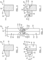
- FIGS 5-7 depict another bidirectional read/write head 84 example not covered by the claims, with a body 86 providing a cylindrical support surface 88.
- An intermediate region 90 includes read/write devices 92.
- a pair of slots 94, 96 is each formed to a fixed depth 98, 100 in the body 86.
- Each slot 94, 96 provides a transverse sidewall 102, 104 and a pair of angled sidewalls 106, 108, 110, 112 that are angled relative to the transverse sidewall 102, 104 and a longitudinal direction.
- the blind depths 98, 100 and the angled sidewalls 106, 108, 110, 112 intersect a respective longitudinal edge 114, 116 of the read/write head 84.
- outboard regions 118, 120 replace the function of additional outriggers.
- the angled sidewalls 106, 108, 110, 112 and the blind depths 98, 100 could be formed as a continuous surface.
- the shape of the slots 94, 96 could be defined by a particular manufacturing process employed for providing the slots 94, 96.
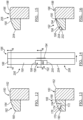
- Figures 8-10 depict yet another bidirectional read/write head 122 example not covered by the claims, with a body 124 providing a cylindrical support surface 126.
- An intermediate region 128 includes read/write devices 130.
- a pair of slots 132, 134 is each formed in the body 124.
- Each slot 132, 134 provides a pair of longitudinal sidewalls 140, 142, 144, 146 that are angled relative to a transverse direction and a longitudinal direction.
- Each slot 132, 134 further provides a planar surface 148, 150 that intersects a respective longitudinal edge 152, 154 of the read/write head 122.
- outboard regions 156, 158 replace the function of additional outriggers.
- the slots 60, 62, 94, 96, 132, 134 can be embodied in various shapes with a width that spans that of the corresponding read/write devices 58, 92, 130 to provide exposure to atmospheric pressure. Different slot shapes may be created by the use of different processes to create the slot. Some such shapes are shown in Figures 2-10 for bidirectional hybrid modules. Unidirectional hybrid modules are also contemplated.
- Figures 11-13 depict a unidirectional read/write head 160 example not covered by the claims, with a body 162 providing a cylindrical support surface 164.
- An intermediate region 166 includes read/write devices 168.
- a slot 170 is formed to a fixed depth 172 in the body 162.
- the slot 170 provides a transverse sidewall 174 and a pair of angled sidewalls 176, 178, that are angled relative to the transverse sidewall 174 and a longitudinal direction.
- the blind depth 172 and the angled sidewalls 176, 178 intersect a longitudinal edge 180 of the read/write head 160.
- the angled sidewalls 176, 178 and the blind depth 172 could be formed as a continuous surface. Similar to the prior embodiments or examples outboard regions 182, 184 replace the function of additional outriggers.
- Figures 14-16 depict another unidirectional read/write head 186 example not covered by the claims, with a body 188 providing a cylindrical support surface 190.
- An intermediate region 192 includes read/write devices 194.
- a slot 196 is formed in the body 188.
- the slot 196 provides a pair of longitudinal sidewalls 198, 200 that are angled relative to a transverse direction and a longitudinal direction.
- the slot 196 further provides a planar surface 202 that intersects a longitudinal edge 204 of the read/write head 186. Similar to the prior embodiments or examples outboard regions 206, 208 replace the function of additional outriggers.
- Figures 17-20 depict yet another unidirectional read/write head 210 embodiment with a body 212 providing a cylindrical support surface 214.
- An intermediate region 216 includes read/write devices 218.
- a slot 220 is formed to a fixed depth 222 in the body 212.
- the slot 220 provides a pair of transverse sidewalls 224, 226 and a pair of angled sidewalls 228, 230, that are angled relative to the transverse sidewalls 224, 226 and a longitudinal direction.
- a second slot 232 intersects a longitudinal edge 234 of the read/write head 160 and the transverse sidewall 226 for exposure to atmospheric pressures. Similar to the prior embodiments, outboard regions 236, 238 replace the function of additional outriggers.
- a duplication of geometries can be employed for obtaining a bidirectional read/write head.
- the sidewalls 224, 226, 228, 230 could also be formed as a continuous surface.
- the transverse sidewalls 224, 226 and the angled sidewalls 228, 230 are an example of geometries resulting from the addition of the slot 220.
- the various embodiments reduce the quantity of separate components that need to be fabricated and assembled during the head manufacturing process. As a result, it reduces the physical size of the head, allowing easier integration of the head into the tape drive system. This solution also provides flexibility to set the wrap angle during the integration of the head in the tape path during drive manufacture. Together, this solution produces less expensive head assemblies and consequently, less expensive drive systems.
- the various embodiments facilitate a less expensive head (and therefore a less expensive tape drive system) without compromising contour performance requirements.
- head-tape friction By reducing the head-tape friction, use of smoother tapes (for higher linear recording densities) is permitted, essentially increasing tape cartridge capacities.
Landscapes
- Engineering & Computer Science (AREA)
- Manufacturing & Machinery (AREA)
- Adjustment Of The Magnetic Head Position Track Following On Tapes (AREA)
- Magnetic Heads (AREA)
- Recording Or Reproducing By Magnetic Means (AREA)
- Magnetic Record Carriers (AREA)
Applications Claiming Priority (2)
| Application Number | Priority Date | Filing Date | Title |
|---|---|---|---|
| US13/973,408 US9001464B2 (en) | 2013-08-22 | 2013-08-22 | Read/write head with improved contact |
| PCT/US2014/049333 WO2015026504A1 (en) | 2013-08-22 | 2014-08-01 | Read/write head with improved contact |
Publications (2)
| Publication Number | Publication Date |
|---|---|
| EP3036740A1 EP3036740A1 (en) | 2016-06-29 |
| EP3036740B1 true EP3036740B1 (en) | 2023-05-24 |
Family
ID=51359437
Family Applications (1)
| Application Number | Title | Priority Date | Filing Date |
|---|---|---|---|
| EP14752977.0A Active EP3036740B1 (en) | 2013-08-22 | 2014-08-01 | Read/write head with improved contact |
Country Status (7)
Families Citing this family (5)
| Publication number | Priority date | Publication date | Assignee | Title |
|---|---|---|---|---|
| US10109310B2 (en) | 2017-03-23 | 2018-10-23 | International Business Machines Corporation | Tape head having sub-ambient channel and methods of manufacture |
| US10522182B1 (en) | 2018-08-20 | 2019-12-31 | International Business Machines Corporation | Tape drive with gas jet impinging on tape |
| US10657989B1 (en) * | 2018-12-18 | 2020-05-19 | International Business Machines Corporation | Tape head module having recessed portion(s) and air aperture(s) for providing an air bearing between a tape and the module |
| US11087786B1 (en) | 2020-04-30 | 2021-08-10 | Western Digital Technologies, Inc. | Tape drive with head-gimbal assembly and contact plate |
| US12406689B2 (en) * | 2023-10-26 | 2025-09-02 | Western Digital Technologies, Inc. | Notched head design for tape applications |
Citations (1)
| Publication number | Priority date | Publication date | Assignee | Title |
|---|---|---|---|---|
| JPH0744821A (ja) * | 1993-07-27 | 1995-02-14 | Matsushita Electric Ind Co Ltd | 薄膜磁気ヘッド |
Family Cites Families (8)
| Publication number | Priority date | Publication date | Assignee | Title |
|---|---|---|---|---|
| JPS60123711U (ja) * | 1984-01-25 | 1985-08-21 | 富士通株式会社 | 磁気ヘツド |
| US6118626A (en) * | 1997-03-11 | 2000-09-12 | Massachusetts Institute Of Technology | Contact sheet recording with a self-acting negative air bearing |
| US5883770A (en) | 1997-07-18 | 1999-03-16 | International Business Machines Corporation | Partial width mass produced linear tape recording head |
| US6236537B1 (en) * | 1997-10-28 | 2001-05-22 | Hewlett-Packard Co. | Wear resistant magnetic write head |
| US6122147A (en) * | 1999-01-05 | 2000-09-19 | Imation Corp. | Negative pressure head contour in a linear tape recording system with tape deforming cavity |
| US6433959B1 (en) | 2000-10-30 | 2002-08-13 | Storage Technology Corporation | Tape head contour utilizing enclosed through slots |
| JP4470808B2 (ja) * | 2004-10-01 | 2010-06-02 | ソニー株式会社 | 磁気ヘッド、磁気記録再生装置、及び、磁気ヘッドの製造方法 |
| US8679733B2 (en) | 2011-01-19 | 2014-03-25 | International Business Machines Corporation | Patterning process for small devices |
-
2013
- 2013-08-22 US US13/973,408 patent/US9001464B2/en active Active
-
2014
- 2014-08-01 AU AU2014309337A patent/AU2014309337B2/en active Active
- 2014-08-01 NZ NZ717036A patent/NZ717036A/en unknown
- 2014-08-01 JP JP2016536276A patent/JP6445014B2/ja active Active
- 2014-08-01 WO PCT/US2014/049333 patent/WO2015026504A1/en active Application Filing
- 2014-08-01 EP EP14752977.0A patent/EP3036740B1/en active Active
- 2014-08-01 CN CN201480053369.7A patent/CN105593937B/zh active Active
Patent Citations (1)
| Publication number | Priority date | Publication date | Assignee | Title |
|---|---|---|---|---|
| JPH0744821A (ja) * | 1993-07-27 | 1995-02-14 | Matsushita Electric Ind Co Ltd | 薄膜磁気ヘッド |
Also Published As
| Publication number | Publication date |
|---|---|
| WO2015026504A1 (en) | 2015-02-26 |
| EP3036740A1 (en) | 2016-06-29 |
| JP2016528661A (ja) | 2016-09-15 |
| NZ717036A (en) | 2020-05-29 |
| US20150055244A1 (en) | 2015-02-26 |
| AU2014309337A1 (en) | 2016-03-10 |
| JP6445014B2 (ja) | 2018-12-26 |
| AU2014309337B2 (en) | 2019-04-04 |
| CN105593937B (zh) | 2019-04-30 |
| CN105593937A (zh) | 2016-05-18 |
| US9001464B2 (en) | 2015-04-07 |
Similar Documents
| Publication | Publication Date | Title |
|---|---|---|
| EP3036740B1 (en) | Read/write head with improved contact | |
| US8223456B2 (en) | Method for manufacturing a magnetic head with mini-outriggers | |
| US8373944B2 (en) | Low friction tape head and system implementing same | |
| US10902868B2 (en) | Tape head module having recessed portion to provide an air bearing between a tape medium and a tape bearing surface of the module | |
| US20100118435A1 (en) | Magnetic head with planar outrigger | |
| US6937435B2 (en) | Tape head with thin support surface and method of manufacture | |
| US20110002065A1 (en) | Recording heads with embedded tape guides and magnetic media made by such recording heads | |
| CN103377657B (zh) | 具有绗缝型涂层的模块、数据存储系统和磁记录头 | |
| US10657989B1 (en) | Tape head module having recessed portion(s) and air aperture(s) for providing an air bearing between a tape and the module | |
| US7256963B2 (en) | Magnetic head with adaptive data island and mini-outrigger and methods of manufacture | |
| US10262684B2 (en) | Tape head formed with high accuracy tape bearing surface length definition process | |
| US6994293B1 (en) | Tape drive transport roller | |
| JP4150065B1 (ja) | 磁気テープ装置 | |
| US20190341071A1 (en) | Forming recessed portions in a tape head module to provide an air bearing between a tape medium and a tape bearing surface of the tape head module | |
| US20100196739A1 (en) | Magnetic head, manufacturing method therefor and magnetic tape device | |
| US20100214690A1 (en) | Roller guide for magnetic tape with multiple guiding sections | |
| JP2005276267A (ja) | 磁気ヘッド装置および磁気テープドライブ装置 | |
| US9741367B1 (en) | Fabrication of a tape head with a monobloc closure | |
| JP2006059472A (ja) | リニアテープドライブ装置 | |
| JP2005216386A (ja) | リニアテープドライブ装置及び磁気ヘッド装置 |
Legal Events
| Date | Code | Title | Description |
|---|---|---|---|
| PUAI | Public reference made under article 153(3) epc to a published international application that has entered the european phase |
Free format text: ORIGINAL CODE: 0009012 |
|
| 17P | Request for examination filed |
Effective date: 20160322 |
|
| AK | Designated contracting states |
Kind code of ref document: A1 Designated state(s): AL AT BE BG CH CY CZ DE DK EE ES FI FR GB GR HR HU IE IS IT LI LT LU LV MC MK MT NL NO PL PT RO RS SE SI SK SM TR |
|
| AX | Request for extension of the european patent |
Extension state: BA ME |
|
| DAX | Request for extension of the european patent (deleted) | ||
| STAA | Information on the status of an ep patent application or granted ep patent |
Free format text: STATUS: EXAMINATION IS IN PROGRESS |
|
| 17Q | First examination report despatched |
Effective date: 20190627 |
|
| GRAP | Despatch of communication of intention to grant a patent |
Free format text: ORIGINAL CODE: EPIDOSNIGR1 |
|
| STAA | Information on the status of an ep patent application or granted ep patent |
Free format text: STATUS: GRANT OF PATENT IS INTENDED |
|
| INTG | Intention to grant announced |
Effective date: 20221216 |
|
| GRAS | Grant fee paid |
Free format text: ORIGINAL CODE: EPIDOSNIGR3 |
|
| GRAA | (expected) grant |
Free format text: ORIGINAL CODE: 0009210 |
|
| STAA | Information on the status of an ep patent application or granted ep patent |
Free format text: STATUS: THE PATENT HAS BEEN GRANTED |
|
| AK | Designated contracting states |
Kind code of ref document: B1 Designated state(s): AL AT BE BG CH CY CZ DE DK EE ES FI FR GB GR HR HU IE IS IT LI LT LU LV MC MK MT NL NO PL PT RO RS SE SI SK SM TR |
|
| REG | Reference to a national code |
Ref country code: GB Ref legal event code: FG4D |
|
| REG | Reference to a national code |
Ref country code: CH Ref legal event code: EP |
|
| REG | Reference to a national code |
Ref country code: DE Ref legal event code: R096 Ref document number: 602014087026 Country of ref document: DE |
|
| REG | Reference to a national code |
Ref country code: AT Ref legal event code: REF Ref document number: 1570055 Country of ref document: AT Kind code of ref document: T Effective date: 20230615 |
|
| REG | Reference to a national code |
Ref country code: IE Ref legal event code: FG4D |
|
| P01 | Opt-out of the competence of the unified patent court (upc) registered |
Effective date: 20230522 |
|
| P02 | Opt-out of the competence of the unified patent court (upc) changed |
Effective date: 20230731 |
|
| REG | Reference to a national code |
Ref country code: LT Ref legal event code: MG9D |
|
| REG | Reference to a national code |
Ref country code: NL Ref legal event code: MP Effective date: 20230524 |
|
| REG | Reference to a national code |
Ref country code: AT Ref legal event code: MK05 Ref document number: 1570055 Country of ref document: AT Kind code of ref document: T Effective date: 20230524 |
|
| PG25 | Lapsed in a contracting state [announced via postgrant information from national office to epo] |
Ref country code: SE Free format text: LAPSE BECAUSE OF FAILURE TO SUBMIT A TRANSLATION OF THE DESCRIPTION OR TO PAY THE FEE WITHIN THE PRESCRIBED TIME-LIMIT Effective date: 20230524 Ref country code: PT Free format text: LAPSE BECAUSE OF FAILURE TO SUBMIT A TRANSLATION OF THE DESCRIPTION OR TO PAY THE FEE WITHIN THE PRESCRIBED TIME-LIMIT Effective date: 20230925 Ref country code: NO Free format text: LAPSE BECAUSE OF FAILURE TO SUBMIT A TRANSLATION OF THE DESCRIPTION OR TO PAY THE FEE WITHIN THE PRESCRIBED TIME-LIMIT Effective date: 20230824 Ref country code: NL Free format text: LAPSE BECAUSE OF FAILURE TO SUBMIT A TRANSLATION OF THE DESCRIPTION OR TO PAY THE FEE WITHIN THE PRESCRIBED TIME-LIMIT Effective date: 20230524 Ref country code: ES Free format text: LAPSE BECAUSE OF FAILURE TO SUBMIT A TRANSLATION OF THE DESCRIPTION OR TO PAY THE FEE WITHIN THE PRESCRIBED TIME-LIMIT Effective date: 20230524 Ref country code: AT Free format text: LAPSE BECAUSE OF FAILURE TO SUBMIT A TRANSLATION OF THE DESCRIPTION OR TO PAY THE FEE WITHIN THE PRESCRIBED TIME-LIMIT Effective date: 20230524 |
|
| PG25 | Lapsed in a contracting state [announced via postgrant information from national office to epo] |
Ref country code: RS Free format text: LAPSE BECAUSE OF FAILURE TO SUBMIT A TRANSLATION OF THE DESCRIPTION OR TO PAY THE FEE WITHIN THE PRESCRIBED TIME-LIMIT Effective date: 20230524 Ref country code: PL Free format text: LAPSE BECAUSE OF FAILURE TO SUBMIT A TRANSLATION OF THE DESCRIPTION OR TO PAY THE FEE WITHIN THE PRESCRIBED TIME-LIMIT Effective date: 20230524 Ref country code: LV Free format text: LAPSE BECAUSE OF FAILURE TO SUBMIT A TRANSLATION OF THE DESCRIPTION OR TO PAY THE FEE WITHIN THE PRESCRIBED TIME-LIMIT Effective date: 20230524 Ref country code: LT Free format text: LAPSE BECAUSE OF FAILURE TO SUBMIT A TRANSLATION OF THE DESCRIPTION OR TO PAY THE FEE WITHIN THE PRESCRIBED TIME-LIMIT Effective date: 20230524 Ref country code: IS Free format text: LAPSE BECAUSE OF FAILURE TO SUBMIT A TRANSLATION OF THE DESCRIPTION OR TO PAY THE FEE WITHIN THE PRESCRIBED TIME-LIMIT Effective date: 20230924 Ref country code: HR Free format text: LAPSE BECAUSE OF FAILURE TO SUBMIT A TRANSLATION OF THE DESCRIPTION OR TO PAY THE FEE WITHIN THE PRESCRIBED TIME-LIMIT Effective date: 20230524 Ref country code: GR Free format text: LAPSE BECAUSE OF FAILURE TO SUBMIT A TRANSLATION OF THE DESCRIPTION OR TO PAY THE FEE WITHIN THE PRESCRIBED TIME-LIMIT Effective date: 20230825 |
|
| PG25 | Lapsed in a contracting state [announced via postgrant information from national office to epo] |
Ref country code: FI Free format text: LAPSE BECAUSE OF FAILURE TO SUBMIT A TRANSLATION OF THE DESCRIPTION OR TO PAY THE FEE WITHIN THE PRESCRIBED TIME-LIMIT Effective date: 20230524 |
|
| PG25 | Lapsed in a contracting state [announced via postgrant information from national office to epo] |
Ref country code: SK Free format text: LAPSE BECAUSE OF FAILURE TO SUBMIT A TRANSLATION OF THE DESCRIPTION OR TO PAY THE FEE WITHIN THE PRESCRIBED TIME-LIMIT Effective date: 20230524 |
|
| PG25 | Lapsed in a contracting state [announced via postgrant information from national office to epo] |
Ref country code: SM Free format text: LAPSE BECAUSE OF FAILURE TO SUBMIT A TRANSLATION OF THE DESCRIPTION OR TO PAY THE FEE WITHIN THE PRESCRIBED TIME-LIMIT Effective date: 20230524 Ref country code: SK Free format text: LAPSE BECAUSE OF FAILURE TO SUBMIT A TRANSLATION OF THE DESCRIPTION OR TO PAY THE FEE WITHIN THE PRESCRIBED TIME-LIMIT Effective date: 20230524 Ref country code: RO Free format text: LAPSE BECAUSE OF FAILURE TO SUBMIT A TRANSLATION OF THE DESCRIPTION OR TO PAY THE FEE WITHIN THE PRESCRIBED TIME-LIMIT Effective date: 20230524 Ref country code: EE Free format text: LAPSE BECAUSE OF FAILURE TO SUBMIT A TRANSLATION OF THE DESCRIPTION OR TO PAY THE FEE WITHIN THE PRESCRIBED TIME-LIMIT Effective date: 20230524 Ref country code: DK Free format text: LAPSE BECAUSE OF FAILURE TO SUBMIT A TRANSLATION OF THE DESCRIPTION OR TO PAY THE FEE WITHIN THE PRESCRIBED TIME-LIMIT Effective date: 20230524 Ref country code: CZ Free format text: LAPSE BECAUSE OF FAILURE TO SUBMIT A TRANSLATION OF THE DESCRIPTION OR TO PAY THE FEE WITHIN THE PRESCRIBED TIME-LIMIT Effective date: 20230524 |
|
| REG | Reference to a national code |
Ref country code: DE Ref legal event code: R097 Ref document number: 602014087026 Country of ref document: DE |
|
| PG25 | Lapsed in a contracting state [announced via postgrant information from national office to epo] |
Ref country code: MC Free format text: LAPSE BECAUSE OF FAILURE TO SUBMIT A TRANSLATION OF THE DESCRIPTION OR TO PAY THE FEE WITHIN THE PRESCRIBED TIME-LIMIT Effective date: 20230524 |
|
| REG | Reference to a national code |
Ref country code: CH Ref legal event code: PL |
|
| PG25 | Lapsed in a contracting state [announced via postgrant information from national office to epo] |
Ref country code: MC Free format text: LAPSE BECAUSE OF FAILURE TO SUBMIT A TRANSLATION OF THE DESCRIPTION OR TO PAY THE FEE WITHIN THE PRESCRIBED TIME-LIMIT Effective date: 20230524 |
|
| PLBE | No opposition filed within time limit |
Free format text: ORIGINAL CODE: 0009261 |
|
| STAA | Information on the status of an ep patent application or granted ep patent |
Free format text: STATUS: NO OPPOSITION FILED WITHIN TIME LIMIT |
|
| PG25 | Lapsed in a contracting state [announced via postgrant information from national office to epo] |
Ref country code: LU Free format text: LAPSE BECAUSE OF NON-PAYMENT OF DUE FEES Effective date: 20230801 |
|
| PG25 | Lapsed in a contracting state [announced via postgrant information from national office to epo] |
Ref country code: LU Free format text: LAPSE BECAUSE OF NON-PAYMENT OF DUE FEES Effective date: 20230801 Ref country code: CH Free format text: LAPSE BECAUSE OF NON-PAYMENT OF DUE FEES Effective date: 20230831 |
|
| 26N | No opposition filed |
Effective date: 20240227 |
|
| PG25 | Lapsed in a contracting state [announced via postgrant information from national office to epo] |
Ref country code: SI Free format text: LAPSE BECAUSE OF FAILURE TO SUBMIT A TRANSLATION OF THE DESCRIPTION OR TO PAY THE FEE WITHIN THE PRESCRIBED TIME-LIMIT Effective date: 20230524 |
|
| REG | Reference to a national code |
Ref country code: BE Ref legal event code: MM Effective date: 20230831 |
|
| REG | Reference to a national code |
Ref country code: IE Ref legal event code: MM4A |
|
| PG25 | Lapsed in a contracting state [announced via postgrant information from national office to epo] |
Ref country code: SI Free format text: LAPSE BECAUSE OF FAILURE TO SUBMIT A TRANSLATION OF THE DESCRIPTION OR TO PAY THE FEE WITHIN THE PRESCRIBED TIME-LIMIT Effective date: 20230524 Ref country code: IT Free format text: LAPSE BECAUSE OF FAILURE TO SUBMIT A TRANSLATION OF THE DESCRIPTION OR TO PAY THE FEE WITHIN THE PRESCRIBED TIME-LIMIT Effective date: 20230524 |
|
| PG25 | Lapsed in a contracting state [announced via postgrant information from national office to epo] |
Ref country code: IE Free format text: LAPSE BECAUSE OF NON-PAYMENT OF DUE FEES Effective date: 20230801 |
|
| PG25 | Lapsed in a contracting state [announced via postgrant information from national office to epo] |
Ref country code: IE Free format text: LAPSE BECAUSE OF NON-PAYMENT OF DUE FEES Effective date: 20230801 Ref country code: FR Free format text: LAPSE BECAUSE OF NON-PAYMENT OF DUE FEES Effective date: 20230831 |
|
| PG25 | Lapsed in a contracting state [announced via postgrant information from national office to epo] |
Ref country code: BE Free format text: LAPSE BECAUSE OF NON-PAYMENT OF DUE FEES Effective date: 20230831 |
|
| PGFP | Annual fee paid to national office [announced via postgrant information from national office to epo] |
Ref country code: DE Payment date: 20240702 Year of fee payment: 11 |
|
| PGFP | Annual fee paid to national office [announced via postgrant information from national office to epo] |
Ref country code: GB Payment date: 20240701 Year of fee payment: 11 |
|
| PG25 | Lapsed in a contracting state [announced via postgrant information from national office to epo] |
Ref country code: BG Free format text: LAPSE BECAUSE OF FAILURE TO SUBMIT A TRANSLATION OF THE DESCRIPTION OR TO PAY THE FEE WITHIN THE PRESCRIBED TIME-LIMIT Effective date: 20230524 |
|
| PG25 | Lapsed in a contracting state [announced via postgrant information from national office to epo] |
Ref country code: BG Free format text: LAPSE BECAUSE OF FAILURE TO SUBMIT A TRANSLATION OF THE DESCRIPTION OR TO PAY THE FEE WITHIN THE PRESCRIBED TIME-LIMIT Effective date: 20230524 |
|
| PG25 | Lapsed in a contracting state [announced via postgrant information from national office to epo] |
Ref country code: CY Free format text: LAPSE BECAUSE OF FAILURE TO SUBMIT A TRANSLATION OF THE DESCRIPTION OR TO PAY THE FEE WITHIN THE PRESCRIBED TIME-LIMIT; INVALID AB INITIO Effective date: 20140801 |
|
| PG25 | Lapsed in a contracting state [announced via postgrant information from national office to epo] |
Ref country code: HU Free format text: LAPSE BECAUSE OF FAILURE TO SUBMIT A TRANSLATION OF THE DESCRIPTION OR TO PAY THE FEE WITHIN THE PRESCRIBED TIME-LIMIT; INVALID AB INITIO Effective date: 20140801 |