EP3032934A1 - Mounting device and part detection method - Google Patents
Mounting device and part detection method Download PDFInfo
- Publication number
- EP3032934A1 EP3032934A1 EP13891019.5A EP13891019A EP3032934A1 EP 3032934 A1 EP3032934 A1 EP 3032934A1 EP 13891019 A EP13891019 A EP 13891019A EP 3032934 A1 EP3032934 A1 EP 3032934A1
- Authority
- EP
- European Patent Office
- Prior art keywords
- component
- mounting
- mounting head
- fiducial mark
- components
- Prior art date
- Legal status (The legal status is an assumption and is not a legal conclusion. Google has not performed a legal analysis and makes no representation as to the accuracy of the status listed.)
- Granted
Links
Images




Classifications
-
- H—ELECTRICITY
- H05—ELECTRIC TECHNIQUES NOT OTHERWISE PROVIDED FOR
- H05K—PRINTED CIRCUITS; CASINGS OR CONSTRUCTIONAL DETAILS OF ELECTRIC APPARATUS; MANUFACTURE OF ASSEMBLAGES OF ELECTRICAL COMPONENTS
- H05K13/00—Apparatus or processes specially adapted for manufacturing or adjusting assemblages of electric components
- H05K13/08—Monitoring manufacture of assemblages
-
- H—ELECTRICITY
- H05—ELECTRIC TECHNIQUES NOT OTHERWISE PROVIDED FOR
- H05K—PRINTED CIRCUITS; CASINGS OR CONSTRUCTIONAL DETAILS OF ELECTRIC APPARATUS; MANUFACTURE OF ASSEMBLAGES OF ELECTRICAL COMPONENTS
- H05K13/00—Apparatus or processes specially adapted for manufacturing or adjusting assemblages of electric components
- H05K13/04—Mounting of components, e.g. of leadless components
- H05K13/0404—Pick-and-place heads or apparatus, e.g. with jaws
- H05K13/0408—Incorporating a pick-up tool
- H05K13/041—Incorporating a pick-up tool having multiple pick-up tools
-
- H—ELECTRICITY
- H05—ELECTRIC TECHNIQUES NOT OTHERWISE PROVIDED FOR
- H05K—PRINTED CIRCUITS; CASINGS OR CONSTRUCTIONAL DETAILS OF ELECTRIC APPARATUS; MANUFACTURE OF ASSEMBLAGES OF ELECTRICAL COMPONENTS
- H05K13/00—Apparatus or processes specially adapted for manufacturing or adjusting assemblages of electric components
- H05K13/08—Monitoring manufacture of assemblages
- H05K13/081—Integration of optical monitoring devices in assembly lines; Processes using optical monitoring devices specially adapted for controlling devices or machines in assembly lines
- H05K13/0812—Integration of optical monitoring devices in assembly lines; Processes using optical monitoring devices specially adapted for controlling devices or machines in assembly lines the monitoring devices being integrated in the mounting machine, e.g. for monitoring components, leads, component placement
Definitions
- the present invention relates to a mounting machine and a component detection method.
- a mounting machine which is provided with a detection target portion in a position which can be imaged at the same time as a component which is sucked by a suction nozzle, detects a relative positional relationship between the rotational center of the suction nozzle and the detection target portion in advance, images the sucked component and the detection target portion at the same time, and acquires the positional shifting of the center on the component based on the aforementioned relative positional relationship (for example, refer to PTL 1).
- this device it is possible to increase the detection precision of the positional shifting of the component in relation to the rotational center of the suction nozzle.
- the component which is sucked by the suction nozzle may be imaged while moving.
- shifting may arise in the timing even if the imaging is performed when the component passes over the imaging section.
- the invention was made in light of this problem, and a main object of the invention is to provide a mounting machine and a component detection method which are capable of more efficiently detecting the holding state of a moving component.
- the invention adopts the following means in order to achieve the main object described above.
- a mounting machine of the invention mounts one or more components on a substrate, and includes: a mounting head which has a fiducial mark, holds the component, and moves the component onto the substrate; an imaging section which images the mounting head; setting means for setting, out of image data of the fiducial mark and component held by the moving mounting head captured by the imaging section, a processing region containing the component, based on the position of the fiducial mark; and detection means for detecting a state of the component which is held by the mounting head by processing the image data of the set processing region.
- a processing region containing a component is set, based on the position of the fiducial mark, and a state of the component which is held by the mounting head is detected by processing the image data of the set processing region.
- the setting means may set the processing region taking into account the size of the component and the positional shifting amount of the component. In this case, it is possible to set the processing region to a narrower range, and this is preferable.
- the positional shifting amount of the component which is taken into account in the processing region may be a value which is obtained empirically.
- the imaging section may transfer the image data of the set processing region out of the captured image data to the detection means, and the detection means may process the image data of the transferred processing region.
- the detection means may process the image data of the transferred processing region.
- the mounting head may hold a plurality of components, and the setting means may set a plurality of processing regions corresponding to the components.
- the mounting head which holds the plurality of components since the mounting head has more processing regions, it is highly significant to apply the invention in which the holding state of the component is efficiently detected. For example, when the processing regions in which the components are contained overlap each other, it may not be possible to detect the states of the components which are held by the mounting head.
- the invention since it is possible to reduce the size of each of the processing regions, it is possible to further suppress the overlapping of the processing regions of the components, and it is possible to perform the detection of the holding states of the components. It is possible to perform the detection of the holding states of the components even for larger components.
- the mounting head may hold the plurality of components on a circular circumference and may have the fiducial mark on a center portion of the circular circumference. In this case, since it is easy to image the components and the fiducial mark in the same image, it is possible to more reliably detect the holding states of the moving components.
- the mounting head may have the fiducial mark containing detection points arranged on a rectangle. In this case, it is more reliably obtain a fiducial position, and thus, it is possible to more reliably detect the holding state of the moving component.
- the mounting machine of the invention may be provided with control means for moving the mounting head in a state of holding the component, and for causing the imaging section to image the component which is held by the mounting head which is moving in an imaging range of the imaging section and the fiducial mark.
- the setting means may perform detection of the fiducial mark on a predetermined region which is smaller than a region of the image data, and may set the processing region based on the position of the fiducial mark which is detected. In this case, it is possible to more efficiently perform the detection of the fiducial mark in comparison with performing the detection of the fiducial mark in relation to the entirety of the image data.
- the fiducial mark may be formed on the center portion of the plurality of held components, and the setting means may perform the detection of the fiducial mark on a predetermined center region which is smaller than a region of the image data.
- a component detection method of the invention is the component detection method of a mounting machine which mounts one or more components on a substrate and includes a mounting head which has fiducial mark, holds the component, and moves the component onto the substrate and an imaging section which images the component held by the mounting head and the fiducial mark, the method including (a) a step of setting , out of image data of the fiducial mark and component held by the moving mounting head captured by the imaging section, a processing region containing the component, based on the position of the fiducial mark, and (b) a step of detecting a state of the component which is held by the mounting head by processing the image data of the set processing region.
- Fig. 1 is a schematic diagram of the component mounting system 10.
- Fig. 2 is a perspective view of the mounting machine 11.
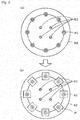
- Fig. 3 is an explanatory diagram of the nozzle holding body 42 as viewed from below, Fig. 3(a) is an explanatory diagram in which no components P are held, and Fig. 3(b) is an explanatory diagram in which the components P are held.
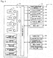
- Fig. 4 is a block diagram representing the electrical connection relationships of the mounting machine 11. Note that, in the present embodiment, the left-right directions (an X axis), the forward-backward directions (a Y axis), and the up-down directions (a Z axis) are as illustrated in Fig. 1 and Fig. 2 .
- the mounting process includes processes such as arranging, mounting, inserting, bonding, and attacking a component onto a substrate.
- the component mounting system 10 is provided with the mounting machines 11 which are configured as a mounting line, and a management computer 80 which manages information of the components to be mounted and the like.
- the plurality of mounting machines 11, each of which carries out a mounting process in which an electronic component (hereinafter referred to as the "component P") is mounted on a substrate S are arranged from upstream to downstream.
- the plurality of mounting machines 11 are provided with the same configuration.
- the mounting machine 11 is provided with a base 12 , a mounting machine main body 14 which is installed on the base 12, and a reel unit 56 onto which a reel 57 which stores the components P is mounted.
- the base 12 is a heavy item formed as a rectangular parallelepiped, and casters which are not depicted in the drawings are attached to the four corners of the reverse surface.
- the mounting machine main body 14 is installed on the base 12 in an exchangeable manner.
- the mounting machine main body 14 is provided with a board conveyance device 18 which conveys the substrate S, a mounting head 24 capable of moving in the XY plane, suction nozzles 40 which are attached to the mounting head 24 and are capable of moving in the Z-axis directions, a camera unit 60 which images the components P which are sucked by the suction nozzles 40, a nozzle stocker 55 which stocks plural types of the suction nozzle 40 which can be attached to the mounting head 24, and a control device 70 (refer to Fig. 4 ) which executes various control.
- a board conveyance device 18 which conveys the substrate S
- a mounting head 24 capable of moving in the XY plane
- suction nozzles 40 which are attached to the mounting head 24 and are capable of moving in the Z-axis directions
- a camera unit 60 which images the components P which are sucked by the suction nozzles 40
- a nozzle stocker 55 which stocks plural
- the board conveyance device 18 is provided with the supporting boards 20 and 20 which are provided to leave an interval in the forward-backward of Fig. 2 and which extend in the left-right directions, and conveyor belts 22 and 22 (only one illustrated in Fig. 2 ) which are provided on surfaces of both the supporting boards 20 and 20 which face each other.
- the conveyor belts 22 and 22 bridge across a drive wheel and a driven wheel which are provided on the left and right of the supporting boards 20 and 20 so as to be endless.
- the substrate S is placed on the top surfaces of the pair of conveyor belts 22 and 22 and is conveyed from the left to the right.
- the substrate S is supported by support pins 23, a multitude of which are provided to stand on the reverse surface side.
- the mounting head 24 holds (sucks) the component P and moves the component P onto the substrate S, and is attached to the front surface of the X-axis slider 26.
- the X-axis slider 26 is attached to the front surface of the Y-axis slider 30 capable of sliding in the forward-backward directions such that the X-axis slider 26 is capable of sliding in the left-right directions.
- the Y-axis slider 30 is attached to a pair of guide rails 32 and 32 which are provided on the left and right to extend in the forward-backward directions such that the Y-axis slider 30 is capable of sliding. Note that, the guide rails 32 and 32 are fixed to the inner portion of the mounting machine 11.
- a pair of guide rails 28 and 28 which are provided on the top and bottom to extend in the left-right directions are provided on the front surface of the Y-axis slider 30, and the X-axis slider 26 is attached to the guide rails 28 and 28 to be capable of sliding in the left-right directions.
- the mounting head 24 moves in the left-right directions in accordance with the movement of the X-axis slider 26 in the left-right directions, and moves in the forward-backward directions together with the movement of the Y-axis slider 30 in the forward-backward directions. Note that, each of the sliders 26 and 30 is driven by a corresponding drive motor.
- the mounting head 24 includes a head main body 41 which is detachably mounted to the X-axis slider 26.
- the nozzle holding body 42 is supported by the head main body 41 to be capable of intermittent rotation, and is intermittently rotated by a rotation device which uses a motor 43 as a drive source.
- a plurality of nozzle holders 44 is held on the circular circumference of the nozzle holding body 42 to be capable of being lifted and lowered, and the suction nozzles 40 which sucks the component are detachably mounted to each of the nozzle holders 44.
- the nozzle holder 44 which is positioned in a predetermined angular position by the intermittent rotation of the nozzle holding body 42 is lifted and lowered in the Z-axis directions (the up-down directions) which orthogonally intersect the X-axis and Y-axis directions by a holder lifting and lowering device which uses a Z-axis motor 46 as a drive source.
- the nozzle holder 44 is capable of sucking the component P using the suction nozzle 40, and of mounting the component P to the substrate S.
- the nozzle holder 44 is rotated (is turned on its axis) by a holder rotation device which uses a motor 47 as drive source, and is able to adjust the angle of the component P which is sucked by the suction nozzle 40.
- fiducial mark 50 which is used for detecting the position of the mounting head 24 is formed on the bottom surface, which can be imaged by the camera unit 60, of the mounting head 24.
- the plurality of (here, eight) suction nozzles 40 are mounted on the circular circumference of the nozzle holding body 42, the plurality of components P is sucked on this circular circumference, and the fiducial mark 50 is present in the center portion of the circular circumference.
- the fiducial mark 50 is formed in the center portion of the mounting head 24 which can be recognized from below, even in a state in which the suction nozzles 40 sucks the components P.
- the fiducial mark 50 contains four detection points which are arranged on a rectangle.
- the fiducial mark 50 is formed in a different color (for example, red) from the peripheral members, and is easy to detect by image processing.
- the suction nozzle 40 sucks a component at the nozzle distal end, releases the component sucked at the nozzle distal end.
- the suction nozzle 40 is connected to one of a vacuum pump and an air pipe via an electromagnetic valve.
- the electromagnetic valve is controlled such that the vacuum pump communicates with the suction nozzle 40, the inner portion of the suction nozzle 40 becomes a negative pressure and the component P is sucked at the distal end.
- the electromagnetic valve is controlled such that the air pipe communicates with the suction nozzle 40, the inner portion of the suction nozzle 40 becomes a positive pressure and the component P sucked at the distal end is released.
- the camera unit 60 is a unit which images the component P sucked by the mounting head 24 and the fiducial mark 50 which is present on the mounting head 24, and is arranged on the front of the supporting board 20 of the front side of the board conveyance device 18.
- the imaging range of the camera unit 60 is above the camera unit 60.
- the camera unit 60 is provided with a lighting section 61 which irradiates the component P sucked by the mounting head 24 with light, and an illumination control section 62 which controls the lighting section 61.
- the camera unit 60 is provided with an image sensor 63 which generates a charge by receiving light and outputs the generated charge, and an image processing section 64 which generates image data based on the charge which is input from the image sensor 63.
- the image sensor 63 may be a CCD, it is preferable to use a CMOS. This is because it is easy to transfer a portion of the image.
- the image processing section 64 executes a process of transferring the image data of a processing region which is set by a region setting section 77 described later in detail, among the captured image data, to the control device 70.
- the camera unit 60 images the component P sucked by the suction nozzle 40 and the fiducial mark 50 and outputs a portion of the imaged result to the control device 70.
- the control device 70 is configured as a microprocessor centered on the CPU 71, is provided with a ROM 72 which stores process programs, an HDD 73 which stores various data, a RAM 74 which is used as a working region, an input-output interface 75 for performing transactions of electrical signals with an external device, and the like, and these are electrically connected via a bus.
- the control device 70 outputs drive signals to the board conveyance device 18, the drive motors of the X-axis slider 26 and the Y-axis slider 30, the Z-axis motor 34 of the mounting head 24, and the electromagnetic valve, and outputs an imaging signal to the camera unit 60.
- the control device 70 receives input of an image signal from the camera unit 60.
- the control device 70 is connected to the reel unit 56, the camera unit 60, and the management computer 80 to be capable of bidirectional communication.
- the sliders 26 and 30 are equipped with position sensors which are not depicted in the drawings, and the control device 70 controls the drive motors of the sliders 26 and 30 while receiving the input of positional information from these position sensors.
- the control device 70 is provided with a mounting control section 76, the region setting section 77, a detection section 78, a determination section 79, and an imaging control section 65 as functional blocks.
- the mounting control section 76 executes a process of mounting the components P based on mounting condition information containing conditions such as the size and the disposition position of each of the components P.
- the mounting control section 76 manages the position (X-Y coordinate) of the mounting head 24 by acquiring the positional information of the drive motor axes of the X-axis slider 26 and the Y-axis slider 30.
- the mounting condition information contains information such as the shape and the size of the component and the disposition position on the substrate S, and is managed by the management computer 80.
- the region setting section 77 executes a process of setting, out of image data of the fiducial mark 50 and one or more components P sucked by the moving mounting head 24 captured by the camera unit 60, the processing region containing the components P, based on the position of the fiducial mark 50.
- the region setting section 77 sets a plurality of processing regions corresponding to each of the components P.
- the region setting section 77 sets a processing region taking into account the size of the component P and the positional shifting amount of the component P.
- the detection section 78 executes a process of detecting the state of the component P which is sucked by the mounting head 24 by processing the image data of the set processing region.
- the detection section 78 executes a process of detecting the shifting amount and the suction angle of the component P which is sucked by the suction nozzle 40 according to the difference between the center position of the component P and the center position of the suction nozzle 40, using an image of the mounting head 24 when no components are mounted as a reference.
- the detection section 78 detects the suction state of the component P in the mounting head 24 based on the captured image.
- the determination section 79 executes a process of determining whether to use the sucked component in the mounting process based on whether the detected shifting amount is greater than a threshold which is predetermined empirically, or, based on whether the shape of the component differs from a reference value.
- the imaging control section 65 executes a process of outputting a signal which causes the camera unit 60 to image the component P which is sucked by the mounting head 24 which is moving in the imaging range of the camera unit 60 and the fiducial mark 50. For example, the imaging control section 65 acquires the position of the managed mounting head 24 every control period of the drive motor axes of the X-axis slider 26 and the Y-axis slider 30, and when the acquired position is a position above the camera unit 60, outputs an imaging signal.
- the management computer 80 is a computer which manages information of the plurality of mounting machines 11, and is provided with a controller which is formed of a CPU, a ROM, a RAM, and the like, and manages the control of the overall device, a communication section which performs communication with external equipment such as the mounting machines 11, and a memory section which stores various application programs and various data files.
- the mounting condition information is stored in the memory section, and the management computer 80 transmits the mounting condition information to the mounting machines 11 according to requests from the mounting machines 11 and the like.
- FIG. 5 is a flowchart representing an example of a mounting process routine which is executed by the CPU 71 of the control device 70.
- This routine is stored on the HDD 73 of the control device 70 and is executed by a start instruction performed by a worker.
- this routine is executed by the CPU 71 using the functions and the units of the imaging control section 65, the mounting control section 76, the region setting section 77, the detection section 78, and the determination section 79 which are the functional blocks of the control device 70.
- the CPU 71 of the control device 70 first acquires the mounting condition information from the management computer 80 and stores the mounting condition information in the HDD 73 (step S100).
- the CPU 71 mounts the nozzle holding body 42 to the mounting head 24 and mounts the suction nozzles 40 to the nozzle holding body 42, images the mounting head 24 which sucks no component P using the camera unit 60, and acquires the result as a reference image (step S110).
- the captured reference image is the same as that illustrated in Fig. 3(a) , and it is possible to ascertain the relative positional relationship (for example, coordinates or the like) between the fiducial mark 50 and each of the suction nozzles 40 from this image.
- the CPU 71 executes the conveying and the fixing processes of the substrate S (step S120), and sets the components P to be mounted on the substrate S based on the content of the mounting condition information (step S130).
- the mounting order of the components P is predetermined and is stored in the mounting condition information.
- the CPU 71 performs the suction and movement processes of the set components P (step S140).
- the suction process the CPU 71 executes a process of moving the mounting head 24 to the pickup positions of the reel units 56 in which the corresponding components are stored, lowering the suction nozzles 40, and sucking the components P by the suction nozzles 40.
- the suction process one or more of the components may be sucked by the mounting head 24.
- the CPU 71 performs a process of causing the mounting head 24 which is sucking the components P to pass over the camera unit 60 and to move to the mounting position of the substrate S.
- the CPU 71 determines whether it is time to perform the imaging based on whether the components P which are sucked by the mounting head 24 are above the camera unit 60 (step S150). The determination can be performed based on whether coordinate of the mounting head 24 which is managed by the mounting control section 76 are positioned above the camera unit 60 (the imaging coordinate). When it is not time to perform the imaging, the CPU 71 simply moves the mounting head 24. On the other hand, when the time to perform the imaging is reached, the CPU 71 outputs an imaging signal which causes the imaging to be executed to the camera unit 60 (step S160). The camera unit 60 which receives the imaging signal executes the imaging process of the image.
- the CPU 71 executes a process of detecting the fiducial mark 50 contained in the captured image data (step S170).
- the detection of the fiducial mark 50 can be performed by determining whether pixels corresponding to the color of the fiducial mark 50 is present in the center region of the image.
- the mounting machine 11 is set to perform the imaging when the mounting head 24 (that is, the fiducial mark 50) is present in approximately the center region.
- the detection of the fiducial mark 50 is performed on a predetermined center region which is smaller than the region of the image data (refer to a center region 95 of Fig. 6 described later). In this case, it is possible to more efficiently perform the detection of the fiducial mark 50 in comparison with performing the detection of the fiducial mark 50 in relation to the entirety of the image data.
- the CPU 71 sets the processing regions in the image in which the components P are anticipated to be present based on the position of the fiducial mark 50 (step S180).
- Fig. 6 is an explanatory diagram of the captured image 90 in which the moving nozzle holding body 42 is imaged.
- Fig. 7 is an explanatory diagram of the processing regions 91 taking the suction shifting amount into account and the enlarged regions 92 taking pickup positional shifting into account in the captured image 90.
- the CPU 71 sets the coordinates of the positions of the suction nozzles 40 to the coordinate at which this positional relationship is obtained in relation to the coordinate of the fiducial mark 50 contained in the image data which is imaged this time.
- the coordinates of the center axis of the suction nozzle 40 are set for the plurality of suction nozzles 40.
- the coordinate values of four detection points may each be used, and the intersection point (center coordinate) of two corner-to-corner lines joining the four detection points may be calculated and used. As illustrated in Fig.
- the CPU 71 sets processing regions in which the coordinates of the axial centers of the suction nozzles 40 and the center coordinates of the processing regions match.
- the processing region is a region of the image data in which the component P is anticipated to be present, and is set as a region which is greater than the area of the component P, taking the size of the component and the suction position shifting of the component into account.
- the mounting machine 11 manages the position of the mounting head 24 according to the positions of the drive motor axes of the X-axis slider 26 and the Y-axis slider 30.
- the camera unit 60 performs an imaging process instantaneously when the mounting head 24 passes over predetermined imaging coordinate.
- the mounting machine 11 can only ascertain the position of the mounting head 24 in units of the control periods of the drive motor axes. Therefore, as indicated by the dotted line in Fig. 6 , in the captured image 90 which is captured, the position of the mounting head 24 may be shifted, at most, by one control period.
- the shifting amount (hereinafter also referred to as the pickup positional shifting) is, at most, 0.75 mm, indicating a large value which cannot be ignored with regard to the components P, for which there has been progress in miniaturization.
- the image processing for ascertaining the state of the component P when an attempt is made to perform the image processing in this state, the presence or absence of the component P should be performed on a region (the enlarged region 92) which is larger than the processing region 91 and takes the pickup positional shifting into account. As illustrated in Fig.
- the mounting head 24 cannot perform a high density arrangement of the suction nozzles 40, or, suction nozzles 40 which cannot suck components P due to the overlapping of the enlarged regions 92 arise. Therefore, in the mounting machine, the processing time of the mounting process may become longer and the efficiency may be reduced.
- the smaller processing region 91 is set, taking only the suction position shifting into account without taking the pickup positional shifting into account by providing the fiducial mark 50 on the mounting head 24 and ascertaining the position of the mounting head 24 by detecting the fiducial mark 50. In this case, even if the component is larger, it is possible to ascertain the suction state during the movement.
- the CPU 71 acquires the image data of the set processing regions (step S190).
- the CPU 71 acquires the image data of the processing regions by the image data of the processing regions being transferred from the image processing section 64 of the camera unit 60.
- the CPU 71 subjects the image data of the processing regions to image processing, and detects the state of the components, specifically, the shifting amount of the components (step S200).
- the control device 70 determines whether each pixel of the image data of the processing region is a pixel corresponding to the component P and detects the region corresponding to the component P.
- the CPU 71 detects the center position of the processing region (that is, the axial center of the suction nozzle 40) and the center position of the sucked component P, and obtains the distance between the detected center positions as the shifting amount. At this time, the CPU 71 may obtain the rotational angle of the component P from the inclination of the shape of the component P, using the correct suction position as a reference. In this manner, it is possible to obtain the shifting amount from the center of the nozzle of the component P which is sucked by the suction nozzle 40.
- the CPU 71 performs the processing without using the sucked component P in the mounting process when the detected shifting amount is greater than a threshold which is empirically determined in advance, or when the shape of the component P differs from a reference value.
- the CPU 71 executes a process of mounting (arranging) the components P in positions which are corrected for the detected shifting amount (step S210). At this time, when the component P is sucked in a rotated state, the CPU 71 rotates the nozzle holder 44 so as to correct that. When the components P are mounted, the CPU 71 determines whether the mounting process of the current substrate by the mounting machine 11 is completed (step S220), and when the mounting process of the current substrate is not completed, the CPU 71 executes step S130 onward.
- the CPU 71 sets the components P to be mounted next, causes the components P to be sucked by the suction nozzles 40, and sets the processing regions 91 containing the components P out of the captured image 90 based on the position of the fiducial mark 50.
- the CPU 71 detects the positional shifting amount of the components P by inspecting the inner portions of the processing regions 91 and repeatedly executes the process of arranging the components P in positions which are corrected for the positional shifting amount. Meanwhile, when the mounting process of the current substrate is completed, the CPU 71 performs a discharge process on the substrate S for which the mounting has been completed (step S230), and determines whether the production is completed based on whether the mounting process has been performed on all of the substrates S (step S240). When the mounting process has not been performed on all of the substrates S, the CPU 71 repeats the processes from step S120 onward, whereas when the mounting process has been performed on all of the substrates S, the routine is ended in this state.
- the mounting head 24 of the present embodiment corresponds to the mounting head
- the camera unit 60 corresponds to the imaging section
- the region setting section 77 corresponds to the setting means
- the detection section 78 corresponds to the detection means.
- the processing region 91 containing the component P is set, based on the position of the fiducial mark 50, and the state of the component P which is sucked by the mounting head 24 is detected by processing the image data of the set processing region 91.
- the processing region 91 in which the component P is thought to be contained may need to be enlarged to a region which takes the positional shifting amount of the mounting head 24 into account.
- the mounting machine 11 of the present embodiment is capable of more efficiently detecting the state of the holding (suction) of the moving component P.
- the mounting machine 11 is capable of further shortening the time of the image processing in which the component P is detected when detecting the suction state of the component P. Since the mounting machine 11 sets the region containing the component P which is sucked by the mounting head 24 after ascertaining the position of the mounting head 24, it is possible to more reliably detect the suction state of the component P.
- the mounting machine 11 Since the mounting machine 11 sets the processing region 91 taking the size of the component and the positional shifting amount of the component into account, it is possible to set the processing region 91 to a narrower range, and this is preferable. Since the mounting machine 11 transfers the image data of the processing region 91 out of the captured image data, and processes the image data of the transferred processing region 91, in comparison to a case in which all of the captured image data is transferred, it is possible to further reduce the transferred data amount, and it is possible to more efficiently detect the suction state of the moving component P. In other words, the mounting machine 11 is capable of further shortening the processing time.
- the mounting head 24 sucks the plurality of components P and sets the plurality of processing regions 91 corresponding to these components P, that is, since the mounting head 24 has more processing regions, it is highly significant to apply the invention in which the suction state of the component P is more efficiently detected. For example, generally, when the processing regions in which the components P are contained overlap each other, faulty detection arises in accordance therewith, or the like, and it may not be possible to detect the states of the components which are held by the mounting head. In the mounting machine 11, since it is possible to reduce the size of each of the processing regions 91, it is possible to further suppress the overlapping of the processing regions of the components, and it is possible to perform the detection of the suction states of the components.
- the mounting head 24 holds the plurality of components P on a circular circumference and has the fiducial mark 50 on the center portion of this circular circumference, it is easy to capture the components P and the fiducial mark 50 in the same image, and it is possible to more reliably detect the suction states of the moving components P. Since the mounting head has the fiducial mark 50 containing the detection points which are arranged on a rectangle, it is possible to more reliably obtain the fiducial position, and thus, it is possible to more reliably detect the suction states of the components P.
- the detection of the fiducial mark 50 is performed on the center region 95 which is smaller than the region of the image data, it is possible to more efficiently perform the detection of the fiducial mark 50 in comparison with performing the detection of the fiducial mark 50 in relation to the entirety of the image data.
- the camera unit 60 transfers only the image data of the set processing region; however, the invention is not particularly limited thereto, and the entirety of the image data may be transferred. Even in this case, since the smaller processing region 91 is used in the image processing in which the component P is detected, it is possible to further shorten the processing time.
- the plurality of components P are sucked on a circular circumference and the fiducial mark 50 is present on the center portion of the circular circumference; however, the invention is not particularly limited thereto.
- the fiducial mark 50 may be formed in any position, as long as the position is possible to image together with the sucked component P using the camera unit 60.
- the plurality of components P may be sucked by the mounting head on a circular circumference and the fiducial mark may be formed outside of the circular circumference.
- the plurality of components P may be sucked by the mounting head on a rectangle and the fiducial mark 50 may be formed on the center portion or the outside of the rectangle.
- the mounting head 24 has the fiducial mark 50 containing the detection points which are arranged on a rectangle; however, as long as it is possible to ascertain the position of the mounting head 24, the invention is not particularly limited thereto, and, for example, the fiducial mark 50 may contain one or more detection points.
- the fiducial mark may contain the detection points arranged on a triangle when there are three detection points, and may contain the detection points arranged on a triangle and in the center when there are four detection points.
- the fiducial mark may contain the detection points arranged on a rectangle and in the middle when there are five detection points, and may contain the detection points on a pentagon.
- the fiducial mark 50 containing the detection points is adopted; however, the shape of the fiducial mark 50 is not limited to the detection points, and a rectangular or polygonal region may be adopted.
- the detection points of the fiducial mark 50 are red; however, for example, the fiducial mark 50 may be easily distinguishable such as blue, white, black, a mirror surface, or the like.
- the detection of the fiducial mark is performed on the center region 95 which is smaller than the region of the image data; however, the invention is not particularly limited thereto.
- the control device 70 may perform the detection of the fiducial mark on a predetermined region which is anticipated to contain the top left detection point of the fiducial mark 50.
- the detection of the fiducial mark may be performed on regions which are anticipated to contain the top right, bottom left, and bottom right detection points.
- control device 70 since the control device 70 performs the detection process of the fiducial mark on narrower regions, it is possible to more efficiently perform the detection of the suction state of the component P.
- the control device 70 may perform the detection of the fiducial mark on a region of the image data without using a predetermined region which is smaller than the region of the image data. Even in this case, since it is possible to cancel out the pickup positional shifting of the mounting head 24 based on the position of the fiducial mark 50, it is possible to more efficiently detect the suction state of the component P.
- control device 70 is provided with the region setting section 77, the detection section 78, and the determination section 79; however, the invention is not particularly limited thereto, and the camera unit 60 may be provided with these. Even in this case, it is possible to more efficiently detect the suction state of the moving component P.
- the camera unit 60 is provided with the region setting section 77 and the like, there are cases in which it is possible to omit a process such as the transferring of the image data, and this is more efficient.
- the component P is sucked by the mounting head 24; however, as long as the component P can be held by the mounting head 24, the mounting head 24 is not limited to those by means of sucking.
- the mounting head 24 may hold the component P by engaging a gripping section with the component P.
- control device 70 may be realized by a CPU executing software, and may be realized in hardware using a circuit or the like.
- the invention is described as the mounting machine 11; however, the invention is not particularly limited thereto, and may be a component detection method or a mode of a program thereof.
Landscapes
- Engineering & Computer Science (AREA)
- Manufacturing & Machinery (AREA)
- Microelectronics & Electronic Packaging (AREA)
- Operations Research (AREA)
- Supply And Installment Of Electrical Components (AREA)
Description
- The present invention relates to a mounting machine and a component detection method.
- In the related art, there is proposed a mounting machine which is provided with a detection target portion in a position which can be imaged at the same time as a component which is sucked by a suction nozzle, detects a relative positional relationship between the rotational center of the suction nozzle and the detection target portion in advance, images the sucked component and the detection target portion at the same time, and acquires the positional shifting of the center on the component based on the aforementioned relative positional relationship (for example, refer to PTL 1). In this device, it is possible to increase the detection precision of the positional shifting of the component in relation to the rotational center of the suction nozzle.
- PTL 1:
JP-A-2002-185198 - Incidentally, when detecting the positional shifting of the component, the component which is sucked by the suction nozzle may be imaged while moving. In this case, although it is possible to obtain a reduction in the time of the mounting process, shifting may arise in the timing even if the imaging is performed when the component passes over the imaging section. In this case, in comparison to a case in which the component is stopped and imaged, it is necessary to perform the detection of the positional shifting of the component by analyzing the image data of a greater range, and there is a problem that the processing takes time. Thus, there is a demand to increase the efficiency of the process of detecting the holding state of the component.
- The invention was made in light of this problem, and a main object of the invention is to provide a mounting machine and a component detection method which are capable of more efficiently detecting the holding state of a moving component.
- The invention adopts the following means in order to achieve the main object described above.
- In other words, a mounting machine of the invention mounts one or more components on a substrate, and includes: a mounting head which has a fiducial mark, holds the component, and moves the component onto the substrate; an imaging section which images the mounting head; setting means for setting, out of image data of the fiducial mark and component held by the moving mounting head captured by the imaging section, a processing region containing the component, based on the position of the fiducial mark; and detection means for detecting a state of the component which is held by the mounting head by processing the image data of the set processing region.
- In this mounting machine, out of image data of the fiducial mark and component held by the moving mounting head captured by the imaging section, a processing region containing a component is set, based on the position of the fiducial mark, and a state of the component which is held by the mounting head is detected by processing the image data of the set processing region. When the moving mounting head is imaged, there is a case in which shifting arises in the position of the mounting head. Therefore, out of the captured image data, the processing region in which the component is thought to be contained may need to be enlarged to a region which takes the positional shifting amount of the mounting head into account. In this mounting machine, since the fiducial mark of the mounting head is first used as a reference, it is possible to set the processing region in which the component is anticipated to be contained in the image to a smaller region which does not take the positional shifting amount of the mounting head into consideration. Therefore, in this mounting machine, it is possible to more efficiently detect the holding state of the moving component.
- In the mounting machine of the invention, the setting means may set the processing region taking into account the size of the component and the positional shifting amount of the component. In this case, it is possible to set the processing region to a narrower range, and this is preferable. Here, the positional shifting amount of the component which is taken into account in the processing region may be a value which is obtained empirically.
- In the mounting machine of the invention, the imaging section may transfer the image data of the set processing region out of the captured image data to the detection means, and the detection means may process the image data of the transferred processing region. In this case, in comparison to a case in which all of the captured image data is transferred, since it is possible to further reduce the transferred data amount, it is possible to more efficiently detect the holding state of the moving component.
- In the mounting machine of the invention, the mounting head may hold a plurality of components, and the setting means may set a plurality of processing regions corresponding to the components. In the mounting head which holds the plurality of components, since the mounting head has more processing regions, it is highly significant to apply the invention in which the holding state of the component is efficiently detected. For example, when the processing regions in which the components are contained overlap each other, it may not be possible to detect the states of the components which are held by the mounting head. In the invention, since it is possible to reduce the size of each of the processing regions, it is possible to further suppress the overlapping of the processing regions of the components, and it is possible to perform the detection of the holding states of the components. It is possible to perform the detection of the holding states of the components even for larger components.
- In the mounting machine of the invention, the mounting head may hold the plurality of components on a circular circumference and may have the fiducial mark on a center portion of the circular circumference. In this case, since it is easy to image the components and the fiducial mark in the same image, it is possible to more reliably detect the holding states of the moving components.
- In the mounting machine of the invention, the mounting head may have the fiducial mark containing detection points arranged on a rectangle. In this case, it is more reliably obtain a fiducial position, and thus, it is possible to more reliably detect the holding state of the moving component.
- Note that, the mounting machine of the invention may be provided with control means for moving the mounting head in a state of holding the component, and for causing the imaging section to image the component which is held by the mounting head which is moving in an imaging range of the imaging section and the fiducial mark.
- In the mounting machine of the invention, the setting means may perform detection of the fiducial mark on a predetermined region which is smaller than a region of the image data, and may set the processing region based on the position of the fiducial mark which is detected. In this case, it is possible to more efficiently perform the detection of the fiducial mark in comparison with performing the detection of the fiducial mark in relation to the entirety of the image data. Here, the fiducial mark may be formed on the center portion of the plurality of held components, and the setting means may perform the detection of the fiducial mark on a predetermined center region which is smaller than a region of the image data.
- A component detection method of the invention is the component detection method of a mounting machine which mounts one or more components on a substrate and includes a mounting head which has fiducial mark, holds the component, and moves the component onto the substrate and an imaging section which images the component held by the mounting head and the fiducial mark, the method including (a) a step of setting , out of image data of the fiducial mark and component held by the moving mounting head captured by the imaging section, a processing region containing the component, based on the position of the fiducial mark, and (b) a step of detecting a state of the component which is held by the mounting head by processing the image data of the set processing region.
- In this component detection method, in the same manner as the mounting machine described above, since the fiducial mark of the mounting head is first used as a reference, it is possible to set the processing region in which the component is anticipated to be contained to a smaller region which does not take the positional shifting amount of the mounting head into consideration. Therefore, it is possible to more efficiently detect the holding state of the moving component. Note that, in the component detection method, various modes of the mounting machine described above may be adopted, and, steps which realize the functions of the mounting machine described above may be added.
-
- [
Fig. 1] Fig. 1 is a schematic diagram of acomponent mounting system 10. - [
Fig. 2] Fig. 2 is a perspective view of amounting machine 11. - [
Fig. 3] Fig. 3 is an explanatory diagram of anozzle holding body 42 as viewed from below. - [
Fig. 4] Fig. 4 is a block diagram representing the electrical connection relationships of themounting machine 11. - [
Fig. 5] Fig. 5 is a flowchart illustrating an example of a mounting process routine. - [
Fig. 6] Fig. 6 is an explanatory diagram of a capturedimage 90 in which the movingnozzle holding body 42 is imaged. - [
Fig. 7] Fig. 7 is an explanatory diagram ofprocessing regions 91 and enlargedregions 92 in the capturedimage 90. - Hereinafter, description will be given of a favorable embodiment of the invention with reference to the drawings.
Fig. 1 is a schematic diagram of thecomponent mounting system 10.Fig. 2 is a perspective view of themounting machine 11.Fig. 3 is an explanatory diagram of thenozzle holding body 42 as viewed from below,Fig. 3(a) is an explanatory diagram in which no components P are held, andFig. 3(b) is an explanatory diagram in which the components P are held.Fig. 4 is a block diagram representing the electrical connection relationships of themounting machine 11. Note that, in the present embodiment, the left-right directions (an X axis), the forward-backward directions (a Y axis), and the up-down directions (a Z axis) are as illustrated inFig. 1 andFig. 2 . The mounting process includes processes such as arranging, mounting, inserting, bonding, and attacking a component onto a substrate. - The
component mounting system 10 is provided with themounting machines 11 which are configured as a mounting line, and amanagement computer 80 which manages information of the components to be mounted and the like. In thecomponent mounting system 10, the plurality ofmounting machines 11, each of which carries out a mounting process in which an electronic component (hereinafter referred to as the "component P") is mounted on a substrate S, are arranged from upstream to downstream. The plurality ofmounting machines 11 are provided with the same configuration. As illustrated inFig. 2 , themounting machine 11 is provided with abase 12 , a mounting machinemain body 14 which is installed on thebase 12, and areel unit 56 onto which areel 57 which stores the components P is mounted. Thebase 12 is a heavy item formed as a rectangular parallelepiped, and casters which are not depicted in the drawings are attached to the four corners of the reverse surface. - The mounting machine
main body 14 is installed on thebase 12 in an exchangeable manner. The mounting machinemain body 14 is provided with aboard conveyance device 18 which conveys the substrate S, a mountinghead 24 capable of moving in the XY plane,suction nozzles 40 which are attached to the mountinghead 24 and are capable of moving in the Z-axis directions, acamera unit 60 which images the components P which are sucked by thesuction nozzles 40, anozzle stocker 55 which stocks plural types of thesuction nozzle 40 which can be attached to the mountinghead 24, and a control device 70 (refer toFig. 4 ) which executes various control. - The
board conveyance device 18 is provided with the supportingboards Fig. 2 and which extend in the left-right directions, andconveyor belts 22 and 22 (only one illustrated inFig. 2 ) which are provided on surfaces of both the supportingboards conveyor belts boards conveyor belts - The mounting
head 24 holds (sucks) the component P and moves the component P onto the substrate S, and is attached to the front surface of theX-axis slider 26. TheX-axis slider 26 is attached to the front surface of the Y-axis slider 30 capable of sliding in the forward-backward directions such that theX-axis slider 26 is capable of sliding in the left-right directions. The Y-axis slider 30 is attached to a pair ofguide rails axis slider 30 is capable of sliding. Note that, the guide rails 32 and 32 are fixed to the inner portion of the mountingmachine 11. A pair ofguide rails axis slider 30, and theX-axis slider 26 is attached to the guide rails 28 and 28 to be capable of sliding in the left-right directions. The mountinghead 24 moves in the left-right directions in accordance with the movement of theX-axis slider 26 in the left-right directions, and moves in the forward-backward directions together with the movement of the Y-axis slider 30 in the forward-backward directions. Note that, each of thesliders - As illustrated in
Fig. 2 , the mountinghead 24 includes a headmain body 41 which is detachably mounted to theX-axis slider 26. Thenozzle holding body 42 is supported by the headmain body 41 to be capable of intermittent rotation, and is intermittently rotated by a rotation device which uses amotor 43 as a drive source. A plurality ofnozzle holders 44 is held on the circular circumference of thenozzle holding body 42 to be capable of being lifted and lowered, and thesuction nozzles 40 which sucks the component are detachably mounted to each of thenozzle holders 44. Thenozzle holder 44 which is positioned in a predetermined angular position by the intermittent rotation of thenozzle holding body 42 is lifted and lowered in the Z-axis directions (the up-down directions) which orthogonally intersect the X-axis and Y-axis directions by a holder lifting and lowering device which uses a Z-axis motor 46 as a drive source. Thenozzle holder 44 is capable of sucking the component P using thesuction nozzle 40, and of mounting the component P to the substrate S. Thenozzle holder 44 is rotated (is turned on its axis) by a holder rotation device which uses amotor 47 as drive source, and is able to adjust the angle of the component P which is sucked by thesuction nozzle 40. - As illustrated in
Fig. 3 ,fiducial mark 50 which is used for detecting the position of the mountinghead 24 is formed on the bottom surface, which can be imaged by thecamera unit 60, of the mountinghead 24. For example, in this mountinghead 24, the plurality of (here, eight)suction nozzles 40 are mounted on the circular circumference of thenozzle holding body 42, the plurality of components P is sucked on this circular circumference, and thefiducial mark 50 is present in the center portion of the circular circumference. As illustrated inFig. 3(b) , thefiducial mark 50 is formed in the center portion of the mountinghead 24 which can be recognized from below, even in a state in which thesuction nozzles 40 sucks the components P. Thefiducial mark 50 contains four detection points which are arranged on a rectangle. Thefiducial mark 50 is formed in a different color (for example, red) from the peripheral members, and is easy to detect by image processing. - Using pressure, the
suction nozzle 40 sucks a component at the nozzle distal end, releases the component sucked at the nozzle distal end. Thesuction nozzle 40 is connected to one of a vacuum pump and an air pipe via an electromagnetic valve. When the electromagnetic valve is controlled such that the vacuum pump communicates with thesuction nozzle 40, the inner portion of thesuction nozzle 40 becomes a negative pressure and the component P is sucked at the distal end. Meanwhile, when the electromagnetic valve is controlled such that the air pipe communicates with thesuction nozzle 40, the inner portion of thesuction nozzle 40 becomes a positive pressure and the component P sucked at the distal end is released. - As illustrated in
Fig. 2 , thecamera unit 60 is a unit which images the component P sucked by the mountinghead 24 and thefiducial mark 50 which is present on the mountinghead 24, and is arranged on the front of the supportingboard 20 of the front side of theboard conveyance device 18. The imaging range of thecamera unit 60 is above thecamera unit 60. As illustrated inFig. 4 , thecamera unit 60 is provided with alighting section 61 which irradiates the component P sucked by the mountinghead 24 with light, and anillumination control section 62 which controls thelighting section 61. Thecamera unit 60 is provided with animage sensor 63 which generates a charge by receiving light and outputs the generated charge, and animage processing section 64 which generates image data based on the charge which is input from theimage sensor 63. Although theimage sensor 63 may be a CCD, it is preferable to use a CMOS. This is because it is easy to transfer a portion of the image. Theimage processing section 64 executes a process of transferring the image data of a processing region which is set by aregion setting section 77 described later in detail, among the captured image data, to thecontrol device 70. When thesuction nozzle 40 which sucks the component P passes over thecamera unit 60, thecamera unit 60 images the component P sucked by thesuction nozzle 40 and thefiducial mark 50 and outputs a portion of the imaged result to thecontrol device 70. - As illustrated in
Fig. 4 , thecontrol device 70 is configured as a microprocessor centered on theCPU 71, is provided with aROM 72 which stores process programs, anHDD 73 which stores various data, aRAM 74 which is used as a working region, an input-output interface 75 for performing transactions of electrical signals with an external device, and the like, and these are electrically connected via a bus. Thecontrol device 70 outputs drive signals to theboard conveyance device 18, the drive motors of theX-axis slider 26 and the Y-axis slider 30, the Z-axis motor 34 of the mountinghead 24, and the electromagnetic valve, and outputs an imaging signal to thecamera unit 60. Thecontrol device 70 receives input of an image signal from thecamera unit 60. Thecontrol device 70 is connected to thereel unit 56, thecamera unit 60, and themanagement computer 80 to be capable of bidirectional communication. Note that, thesliders control device 70 controls the drive motors of thesliders - The
control device 70 is provided with a mountingcontrol section 76, theregion setting section 77, adetection section 78, adetermination section 79, and animaging control section 65 as functional blocks. The mountingcontrol section 76 executes a process of mounting the components P based on mounting condition information containing conditions such as the size and the disposition position of each of the components P. The mountingcontrol section 76 manages the position (X-Y coordinate) of the mountinghead 24 by acquiring the positional information of the drive motor axes of theX-axis slider 26 and the Y-axis slider 30. For example, the mounting condition information contains information such as the shape and the size of the component and the disposition position on the substrate S, and is managed by themanagement computer 80. Theregion setting section 77 executes a process of setting, out of image data of thefiducial mark 50 and one or more components P sucked by the moving mountinghead 24 captured by thecamera unit 60, the processing region containing the components P, based on the position of thefiducial mark 50. When the plurality of components P is sucked by thesuction nozzles 40, theregion setting section 77 sets a plurality of processing regions corresponding to each of the components P. When theregion setting section 77 sets a processing region containing the component P in the image data, theregion setting section 77 sets a processing region taking into account the size of the component P and the positional shifting amount of the component P. Thedetection section 78 executes a process of detecting the state of the component P which is sucked by the mountinghead 24 by processing the image data of the set processing region. Thedetection section 78 executes a process of detecting the shifting amount and the suction angle of the component P which is sucked by thesuction nozzle 40 according to the difference between the center position of the component P and the center position of thesuction nozzle 40, using an image of the mountinghead 24 when no components are mounted as a reference. Thedetection section 78 detects the suction state of the component P in the mountinghead 24 based on the captured image. Thedetermination section 79 executes a process of determining whether to use the sucked component in the mounting process based on whether the detected shifting amount is greater than a threshold which is predetermined empirically, or, based on whether the shape of the component differs from a reference value. Theimaging control section 65 executes a process of outputting a signal which causes thecamera unit 60 to image the component P which is sucked by the mountinghead 24 which is moving in the imaging range of thecamera unit 60 and thefiducial mark 50. For example, theimaging control section 65 acquires the position of the managed mountinghead 24 every control period of the drive motor axes of theX-axis slider 26 and the Y-axis slider 30, and when the acquired position is a position above thecamera unit 60, outputs an imaging signal. - The
management computer 80 is a computer which manages information of the plurality of mountingmachines 11, and is provided with a controller which is formed of a CPU, a ROM, a RAM, and the like, and manages the control of the overall device, a communication section which performs communication with external equipment such as the mountingmachines 11, and a memory section which stores various application programs and various data files. In themanagement computer 80, the mounting condition information is stored in the memory section, and themanagement computer 80 transmits the mounting condition information to the mountingmachines 11 according to requests from the mountingmachines 11 and the like. - Next, description will be given of the operations of the mounting
machine 11 of the present embodiment which is configured in this manner, for example, the mounting process of imaging the component P which is sucked by thesuction nozzle 40 while moving, and arranging the component P on the substrate S.Fig. 5 is a flowchart representing an example of a mounting process routine which is executed by theCPU 71 of thecontrol device 70. This routine is stored on theHDD 73 of thecontrol device 70 and is executed by a start instruction performed by a worker. For example, this routine is executed by theCPU 71 using the functions and the units of theimaging control section 65, the mountingcontrol section 76, theregion setting section 77, thedetection section 78, and thedetermination section 79 which are the functional blocks of thecontrol device 70. - When the routine is started, the
CPU 71 of thecontrol device 70 first acquires the mounting condition information from themanagement computer 80 and stores the mounting condition information in the HDD 73 (step S100). Next, theCPU 71 mounts thenozzle holding body 42 to the mountinghead 24 and mounts thesuction nozzles 40 to thenozzle holding body 42, images the mountinghead 24 which sucks no component P using thecamera unit 60, and acquires the result as a reference image (step S110). For example, the captured reference image is the same as that illustrated inFig. 3(a) , and it is possible to ascertain the relative positional relationship (for example, coordinates or the like) between thefiducial mark 50 and each of thesuction nozzles 40 from this image. - Next, the
CPU 71 executes the conveying and the fixing processes of the substrate S (step S120), and sets the components P to be mounted on the substrate S based on the content of the mounting condition information (step S130). The mounting order of the components P is predetermined and is stored in the mounting condition information. Next, theCPU 71 performs the suction and movement processes of the set components P (step S140). In the suction process, theCPU 71 executes a process of moving the mountinghead 24 to the pickup positions of thereel units 56 in which the corresponding components are stored, lowering thesuction nozzles 40, and sucking the components P by thesuction nozzles 40. In the suction process, one or more of the components may be sucked by the mountinghead 24. In the movement process, theCPU 71 performs a process of causing the mountinghead 24 which is sucking the components P to pass over thecamera unit 60 and to move to the mounting position of the substrate S. - Subsequently, the
CPU 71 determines whether it is time to perform the imaging based on whether the components P which are sucked by the mountinghead 24 are above the camera unit 60 (step S150). The determination can be performed based on whether coordinate of the mountinghead 24 which is managed by the mountingcontrol section 76 are positioned above the camera unit 60 (the imaging coordinate). When it is not time to perform the imaging, theCPU 71 simply moves the mountinghead 24. On the other hand, when the time to perform the imaging is reached, theCPU 71 outputs an imaging signal which causes the imaging to be executed to the camera unit 60 (step S160). Thecamera unit 60 which receives the imaging signal executes the imaging process of the image. Due to thecamera unit 60 imaging the mountinghead 24 which is moving to the mounting position, it is possible to perform the imaging process in a shorter time in comparison to a case in which, for example, the mountinghead 24 is temporarily stopped and imaged. When the imaging process is executed, theCPU 71 executes a process of detecting thefiducial mark 50 contained in the captured image data (step S170). For example, the detection of thefiducial mark 50 can be performed by determining whether pixels corresponding to the color of thefiducial mark 50 is present in the center region of the image. The mountingmachine 11 is set to perform the imaging when the mounting head 24 (that is, the fiducial mark 50) is present in approximately the center region. Therefore, the detection of thefiducial mark 50 is performed on a predetermined center region which is smaller than the region of the image data (refer to acenter region 95 ofFig. 6 described later). In this case, it is possible to more efficiently perform the detection of thefiducial mark 50 in comparison with performing the detection of thefiducial mark 50 in relation to the entirety of the image data. - When the
fiducial mark 50 is detected, theCPU 71 sets the processing regions in the image in which the components P are anticipated to be present based on the position of the fiducial mark 50 (step S180). Here, description will be given of the setting of the processing region.Fig. 6 is an explanatory diagram of the capturedimage 90 in which the movingnozzle holding body 42 is imaged.Fig. 7 is an explanatory diagram of theprocessing regions 91 taking the suction shifting amount into account and theenlarged regions 92 taking pickup positional shifting into account in the capturedimage 90. First, using the positional relationship between the coordinate of thefiducial mark 50 of the reference image and the coordinates of the center axes of thesuction nozzles 40, theCPU 71 sets the coordinates of the positions of thesuction nozzles 40 to the coordinate at which this positional relationship is obtained in relation to the coordinate of thefiducial mark 50 contained in the image data which is imaged this time. Here, the coordinates of the center axis of thesuction nozzle 40 are set for the plurality ofsuction nozzles 40. Note that, as the coordinate of thefiducial mark 50, for example, the coordinate values of four detection points may each be used, and the intersection point (center coordinate) of two corner-to-corner lines joining the four detection points may be calculated and used. As illustrated inFig. 7 , theCPU 71 sets processing regions in which the coordinates of the axial centers of thesuction nozzles 40 and the center coordinates of the processing regions match. The processing region is a region of the image data in which the component P is anticipated to be present, and is set as a region which is greater than the area of the component P, taking the size of the component and the suction position shifting of the component into account. - Here, description is given of the positional shifting and the like of the component P. Generally, when picking up the component P, due to an effect such as a holding position in a tape, the component P is sucked by the
suction nozzle 40 in accordance with the suction position shifting in which the center of thesuction nozzle 40 is shifted from the center of the component P, and in which the component P rotates by a predetermined angle. Therefore, in the image processing for ascertaining the suction state of the component P, the presence or absence of the component P should be detected in relation to a region (the processing region 91) which takes the size and suction position shifting of the component P into account. The mountingmachine 11 manages the position of the mountinghead 24 according to the positions of the drive motor axes of theX-axis slider 26 and the Y-axis slider 30. Thecamera unit 60 performs an imaging process instantaneously when the mountinghead 24 passes over predetermined imaging coordinate. However, the mountingmachine 11 can only ascertain the position of the mountinghead 24 in units of the control periods of the drive motor axes. Therefore, as indicated by the dotted line inFig. 6 , in the capturedimage 90 which is captured, the position of the mountinghead 24 may be shifted, at most, by one control period. For example, when the movement speed of the mountinghead 24 is 3 m/s and the unit of the control periods of the drive motor axes is 250 µs, the shifting amount (hereinafter also referred to as the pickup positional shifting) is, at most, 0.75 mm, indicating a large value which cannot be ignored with regard to the components P, for which there has been progress in miniaturization. In the image processing for ascertaining the state of the component P, when an attempt is made to perform the image processing in this state, the presence or absence of the component P should be performed on a region (the enlarged region 92) which is larger than theprocessing region 91 and takes the pickup positional shifting into account. As illustrated inFig. 7 , when theenlarged region 92 which takes the pickup positional shifting into consideration overlaps the adjacentenlarged regions 92, this leads to false detection. Therefore, depending on the size of the component P, the mountinghead 24 cannot perform a high density arrangement of thesuction nozzles 40, or,suction nozzles 40 which cannot suck components P due to the overlapping of theenlarged regions 92 arise. Therefore, in the mounting machine, the processing time of the mounting process may become longer and the efficiency may be reduced. In this mountingmachine 11, thesmaller processing region 91 is set, taking only the suction position shifting into account without taking the pickup positional shifting into account by providing thefiducial mark 50 on the mountinghead 24 and ascertaining the position of the mountinghead 24 by detecting thefiducial mark 50. In this case, even if the component is larger, it is possible to ascertain the suction state during the movement. - When the processing regions are set, the
CPU 71 acquires the image data of the set processing regions (step S190). Here, of the entirety of the image data, theCPU 71 acquires the image data of the processing regions by the image data of the processing regions being transferred from theimage processing section 64 of thecamera unit 60. Next, theCPU 71 subjects the image data of the processing regions to image processing, and detects the state of the components, specifically, the shifting amount of the components (step S200). Hereinafter, description will be given of the detection method of the shifting amount of the component. For example, thecontrol device 70 determines whether each pixel of the image data of the processing region is a pixel corresponding to the component P and detects the region corresponding to the component P. Next, theCPU 71 detects the center position of the processing region (that is, the axial center of the suction nozzle 40) and the center position of the sucked component P, and obtains the distance between the detected center positions as the shifting amount. At this time, theCPU 71 may obtain the rotational angle of the component P from the inclination of the shape of the component P, using the correct suction position as a reference. In this manner, it is possible to obtain the shifting amount from the center of the nozzle of the component P which is sucked by thesuction nozzle 40. Note that, although omitted to facilitate description in the flowchart, theCPU 71 performs the processing without using the sucked component P in the mounting process when the detected shifting amount is greater than a threshold which is empirically determined in advance, or when the shape of the component P differs from a reference value. - Next, the
CPU 71 executes a process of mounting (arranging) the components P in positions which are corrected for the detected shifting amount (step S210). At this time, when the component P is sucked in a rotated state, theCPU 71 rotates thenozzle holder 44 so as to correct that. When the components P are mounted, theCPU 71 determines whether the mounting process of the current substrate by the mountingmachine 11 is completed (step S220), and when the mounting process of the current substrate is not completed, theCPU 71 executes step S130 onward. In other words, theCPU 71 sets the components P to be mounted next, causes the components P to be sucked by thesuction nozzles 40, and sets theprocessing regions 91 containing the components P out of the capturedimage 90 based on the position of thefiducial mark 50. TheCPU 71 detects the positional shifting amount of the components P by inspecting the inner portions of theprocessing regions 91 and repeatedly executes the process of arranging the components P in positions which are corrected for the positional shifting amount. Meanwhile, when the mounting process of the current substrate is completed, theCPU 71 performs a discharge process on the substrate S for which the mounting has been completed (step S230), and determines whether the production is completed based on whether the mounting process has been performed on all of the substrates S (step S240). When the mounting process has not been performed on all of the substrates S, theCPU 71 repeats the processes from step S120 onward, whereas when the mounting process has been performed on all of the substrates S, the routine is ended in this state. - Here, the correspondence relationship between the constituent elements of the present embodiment and the constituent elements of the invention will be made clear. The mounting
head 24 of the present embodiment corresponds to the mounting head, thecamera unit 60 corresponds to the imaging section, theregion setting section 77 corresponds to the setting means, and thedetection section 78 corresponds to the detection means. - In the mounting
machine 11 described above, out of the capturedimage data 90 of thefiducial mark 50 and component P held by (sucked by) the moving mountinghead 24, theprocessing region 91 containing the component P is set, based on the position of thefiducial mark 50, and the state of the component P which is sucked by the mountinghead 24 is detected by processing the image data of theset processing region 91. In the mounting machine, when the moving mountinghead 24 is imaged, there is a case in which shifting arises in the position of the mountinghead 24. Therefore, out of the captured image data, theprocessing region 91 in which the component P is thought to be contained may need to be enlarged to a region which takes the positional shifting amount of the mountinghead 24 into account. In this mountingmachine 11, since it is possible to ascertain the position of the mountinghead 24 without shifting, using thefiducial mark 50 of the mountinghead 24 as a reference, it is possible to set theprocessing region 91 in which the component P is anticipated to be contained in the image to a smaller region which does not take the positional shifting amount of the mountinghead 24 into consideration. Therefore, the mountingmachine 11 of the present embodiment is capable of more efficiently detecting the state of the holding (suction) of the moving component P. In particular, the mountingmachine 11 is capable of further shortening the time of the image processing in which the component P is detected when detecting the suction state of the component P. Since the mountingmachine 11 sets the region containing the component P which is sucked by the mountinghead 24 after ascertaining the position of the mountinghead 24, it is possible to more reliably detect the suction state of the component P. - Since the mounting
machine 11 sets theprocessing region 91 taking the size of the component and the positional shifting amount of the component into account, it is possible to set theprocessing region 91 to a narrower range, and this is preferable. Since the mountingmachine 11 transfers the image data of theprocessing region 91 out of the captured image data, and processes the image data of the transferredprocessing region 91, in comparison to a case in which all of the captured image data is transferred, it is possible to further reduce the transferred data amount, and it is possible to more efficiently detect the suction state of the moving component P. In other words, the mountingmachine 11 is capable of further shortening the processing time. Since the mountinghead 24 sucks the plurality of components P and sets the plurality ofprocessing regions 91 corresponding to these components P, that is, since the mountinghead 24 has more processing regions, it is highly significant to apply the invention in which the suction state of the component P is more efficiently detected. For example, generally, when the processing regions in which the components P are contained overlap each other, faulty detection arises in accordance therewith, or the like, and it may not be possible to detect the states of the components which are held by the mounting head. In the mountingmachine 11, since it is possible to reduce the size of each of theprocessing regions 91, it is possible to further suppress the overlapping of the processing regions of the components, and it is possible to perform the detection of the suction states of the components. It is possible to perform the detection of the suction states of the components even for larger components. Since the mountinghead 24 holds the plurality of components P on a circular circumference and has thefiducial mark 50 on the center portion of this circular circumference, it is easy to capture the components P and thefiducial mark 50 in the same image, and it is possible to more reliably detect the suction states of the moving components P. Since the mounting head has thefiducial mark 50 containing the detection points which are arranged on a rectangle, it is possible to more reliably obtain the fiducial position, and thus, it is possible to more reliably detect the suction states of the components P. Since the detection of thefiducial mark 50 is performed on thecenter region 95 which is smaller than the region of the image data, it is possible to more efficiently perform the detection of thefiducial mark 50 in comparison with performing the detection of thefiducial mark 50 in relation to the entirety of the image data. - Note that, the invention is not limited to the embodiment described above, and, needless to say, may be carried out in various modes within the technical scope of the invention.
- For example, in the embodiment described above, the
camera unit 60 transfers only the image data of the set processing region; however, the invention is not particularly limited thereto, and the entirety of the image data may be transferred. Even in this case, since thesmaller processing region 91 is used in the image processing in which the component P is detected, it is possible to further shorten the processing time. - In the embodiment described above, description is given of a configuration in which the mounting
head 24 sucks the plurality of components P; however, the invention is not particularly limited thereto, and a single component P may be sucked. Even in this case, since thesmaller processing region 91 is used in the image processing in which the component P is detected, it is possible to more efficiently detect the suction state of the moving component P. - In the embodiment described above, the plurality of components P are sucked on a circular circumference and the
fiducial mark 50 is present on the center portion of the circular circumference; however, the invention is not particularly limited thereto. For example, thefiducial mark 50 may be formed in any position, as long as the position is possible to image together with the sucked component P using thecamera unit 60. For example, the plurality of components P may be sucked by the mounting head on a circular circumference and the fiducial mark may be formed outside of the circular circumference. The plurality of components P may be sucked by the mounting head on a rectangle and thefiducial mark 50 may be formed on the center portion or the outside of the rectangle. - In the embodiment described above, the mounting
head 24 has thefiducial mark 50 containing the detection points which are arranged on a rectangle; however, as long as it is possible to ascertain the position of the mountinghead 24, the invention is not particularly limited thereto, and, for example, thefiducial mark 50 may contain one or more detection points. For example, the fiducial mark may contain the detection points arranged on a triangle when there are three detection points, and may contain the detection points arranged on a triangle and in the center when there are four detection points. For example, the fiducial mark may contain the detection points arranged on a rectangle and in the middle when there are five detection points, and may contain the detection points on a pentagon. In the embodiment described above, thefiducial mark 50 containing the detection points is adopted; however, the shape of thefiducial mark 50 is not limited to the detection points, and a rectangular or polygonal region may be adopted. The detection points of thefiducial mark 50 are red; however, for example, thefiducial mark 50 may be easily distinguishable such as blue, white, black, a mirror surface, or the like. - In the embodiment described above, the detection of the fiducial mark is performed on the
center region 95 which is smaller than the region of the image data; however, the invention is not particularly limited thereto. For example, when performing the detection of the fiducial mark from the left pixel of the topmost row to the right and from the left pixel of the second row to the right side, thecontrol device 70 may perform the detection of the fiducial mark on a predetermined region which is anticipated to contain the top left detection point of thefiducial mark 50. At this time, since the positional relationship (the coordinates or the like) of the detection points of thefiducial mark 50 is already known, after detecting one detection point, the detection of the fiducial mark may be performed on regions which are anticipated to contain the top right, bottom left, and bottom right detection points. In this case, since thecontrol device 70 performs the detection process of the fiducial mark on narrower regions, it is possible to more efficiently perform the detection of the suction state of the component P. Alternatively, thecontrol device 70 may perform the detection of the fiducial mark on a region of the image data without using a predetermined region which is smaller than the region of the image data. Even in this case, since it is possible to cancel out the pickup positional shifting of the mountinghead 24 based on the position of thefiducial mark 50, it is possible to more efficiently detect the suction state of the component P. - In the embodiment described above, description is given of a configuration in which the
control device 70 is provided with theregion setting section 77, thedetection section 78, and thedetermination section 79; however, the invention is not particularly limited thereto, and thecamera unit 60 may be provided with these. Even in this case, it is possible to more efficiently detect the suction state of the moving component P. In particular, when thecamera unit 60 is provided with theregion setting section 77 and the like, there are cases in which it is possible to omit a process such as the transferring of the image data, and this is more efficient. - In the embodiment described above, the component P is sucked by the mounting
head 24; however, as long as the component P can be held by the mountinghead 24, the mountinghead 24 is not limited to those by means of sucking. For example, the mountinghead 24 may hold the component P by engaging a gripping section with the component P. - Note that, the functional blocks of the
control device 70 described above may be realized by a CPU executing software, and may be realized in hardware using a circuit or the like. - In the embodiment described above, the invention is described as the mounting
machine 11; however, the invention is not particularly limited thereto, and may be a component detection method or a mode of a program thereof. - It is possible to use the invention in the technical field of mounting a component to a substrate.
- 10: component mounting system, 11: mounting machine, 12: base, 14: mounting machine main body, 18: board conveyance device, 20: supporting board, 22: conveyor belt, 23: support pin, 24: mounting head, 26: X-axis slider, 28: guide rail, 30: Y-axis slider, 32: guide rail, 40: suction nozzle, 42: nozzle holding body, 43: motor, 44: nozzle holder, 46: Z-axis motor, 47: motor, 50: fiducial mark, 55: nozzle stocker, 56: reel unit, 60: camera unit, 61: lighting section, 62: illumination control section, 63: image sensor, 64: image processing section, 65: imaging control section, 70: control device, 71: CPU, 72: ROM, 73: HDD, 74: RAM, 75: input-output interface, 76: mounting control section, 77: region setting section, 78: detection section, 79: determination section, 80: management computer, 90: captured image, 91: processing region, 92: enlarged region, 95: center region, P: component, S substrate.
Claims (7)
- A mounting machine which mounts one or more components on a substrate, the mounting machine comprising:a mounting head which includes a fiducial mark, holds the component, and moves the component onto the substrate;an imaging section which images the mounting head;setting means for setting, out of image data of the fiducial mark and component held by the moving mounting head captured by the imaging section, a processing region containing the component, based on the position of the fiducial mark; anddetection means for detecting a state of the component which is held by the mounting head by processing the image data of the set processing region.
- The mounting machine according to Claim 1,
wherein the setting means sets the processing region taking into account the size of the component and the positional shifting amount of the component. - The mounting machine according to Claim 1 or 2,
wherein the imaging section transfers the image data of the set processing region out of the captured image data to the detection means, and
wherein the detection means processes the image data of the transferred processing region. - The mounting machine according to any one of Claims 1 to 3,
wherein the mounting head holds a plurality of components, and
wherein the setting means sets a plurality of processing regions corresponding to the components. - The mounting machine according to Claim 4,
wherein the mounting head holds the plurality of components on a circular circumference and includes the fiducial mark on a center portion of the circular circumference. - The mounting machine according to any one of Claims 1 to 5,
wherein the mounting head has the fiducial mark containing detection points arranged on a rectangle. - A component detection method of a mounting machine which mounts one or more components on a substrate and includes a mounting head which has a fiducial mark, holds the component, and moves the component onto the substrate and an imaging section which images the component held by the mounting head and the fiducial mark, the method comprising:(a) a step of setting, out of image data of the fiducial mark and component held by the moving mounting head captured by the imaging section, a processing region containing the component, based on the position of the fiducial mark; and(b) a step of detecting a state of the component which is held by the mounting head by processing the image data of the set processing region.
Applications Claiming Priority (1)
| Application Number | Priority Date | Filing Date | Title |
|---|---|---|---|
| PCT/JP2013/071639 WO2015019487A1 (en) | 2013-08-09 | 2013-08-09 | Mounting device and part detection method |
Publications (3)
| Publication Number | Publication Date |
|---|---|
| EP3032934A1 true EP3032934A1 (en) | 2016-06-15 |
| EP3032934A4 EP3032934A4 (en) | 2016-08-17 |
| EP3032934B1 EP3032934B1 (en) | 2019-09-25 |
Family
ID=52460854
Family Applications (1)
| Application Number | Title | Priority Date | Filing Date |
|---|---|---|---|
| EP13891019.5A Active EP3032934B1 (en) | 2013-08-09 | 2013-08-09 | Mounting device and part detection method |
Country Status (5)
| Country | Link |
|---|---|
| US (1) | US10314220B2 (en) |
| EP (1) | EP3032934B1 (en) |
| JP (1) | JP6279581B2 (en) |
| CN (1) | CN105453715B (en) |
| WO (1) | WO2015019487A1 (en) |
Cited By (1)
| Publication number | Priority date | Publication date | Assignee | Title |
|---|---|---|---|---|
| EP3407696A4 (en) * | 2016-01-19 | 2019-01-16 | Fuji Corporation | MOUNTING APPARATUS AND IMAGE PROCESSING METHOD |
Families Citing this family (9)
| Publication number | Priority date | Publication date | Assignee | Title |
|---|---|---|---|---|
| JP6770170B2 (en) * | 2017-03-09 | 2020-10-14 | 株式会社Fuji | Parts recognition device |
| CN111096103B (en) * | 2017-09-22 | 2021-10-22 | 株式会社富士 | Electronic component mounting method and electronic component mounting machine |
| EP4567741B1 (en) | 2017-10-31 | 2026-04-29 | Nike Innovate C.V. | Image registration for printing |
| KR102387058B1 (en) * | 2018-02-27 | 2022-04-15 | 야마하하쓰도키 가부시키가이샤 | Parts conveying apparatus, component conveying method and component mounting apparatus |
| JP7197285B2 (en) * | 2018-05-14 | 2022-12-27 | Juki株式会社 | Mounting equipment, mounting method |
| WO2021166220A1 (en) * | 2020-02-21 | 2021-08-26 | ヤマハ発動機株式会社 | Surface mounter and image analyzing method |
| CN111954460B (en) * | 2020-08-01 | 2022-08-09 | 深圳市华成工业控制股份有限公司 | Vision-based automatic soldering tin position correction method and system |
| JP7126285B1 (en) * | 2021-09-17 | 2022-08-26 | 上野精機株式会社 | electronic component processing equipment |
| CN119487471A (en) | 2022-07-27 | 2025-02-18 | 三菱电机株式会社 | Alignment systems, alignment methods and procedures |
Family Cites Families (22)
| Publication number | Priority date | Publication date | Assignee | Title |
|---|---|---|---|---|
| JP2663468B2 (en) * | 1987-12-24 | 1997-10-15 | 松下電器産業株式会社 | Character recognition method |
| JPH0563398A (en) * | 1991-08-22 | 1993-03-12 | Philips Gloeilampenfab:Nv | Component mounting method and component mounting apparatus |
| JP3366497B2 (en) * | 1995-07-12 | 2003-01-14 | 松下電器産業株式会社 | Component detection method |
| US6718626B2 (en) | 2000-09-13 | 2004-04-13 | Fuji Machine Mfg. Co., Ltd. | Apparatus for detecting positioning error of a component with respect to a suction nozzle |
| JP4540837B2 (en) | 2000-12-11 | 2010-09-08 | 富士機械製造株式会社 | Electrical component mounting system and method for obtaining relative positional relationship thereof |
| US6739036B2 (en) | 2000-09-13 | 2004-05-25 | Fuji Machine Mfg., Co., Ltd. | Electric-component mounting system |
| JP2002094296A (en) * | 2000-09-13 | 2002-03-29 | Fuji Mach Mfg Co Ltd | Suction nozzle, method for detecting holding position of electric component, method for detecting curvature of suction tube, method for specifying rotational position of suction nozzle, and electric component handling unit |
| JP2002144267A (en) * | 2000-11-06 | 2002-05-21 | Fuji Mach Mfg Co Ltd | Electric part sucking nozzle, magnification detection method and sucking position detection method |
| JP2002204096A (en) * | 2000-12-28 | 2002-07-19 | Fuji Mach Mfg Co Ltd | Electrical component attaching system and method of attaching electrical component |
| JP4516220B2 (en) * | 2001-01-15 | 2010-08-04 | 富士機械製造株式会社 | Relative positional relationship acquisition method and electrical component mounting system for component mounting accuracy related parts |
| JP4616514B2 (en) * | 2001-06-07 | 2011-01-19 | 富士機械製造株式会社 | Electrical component mounting system and position error detection method therefor |
| US6999835B2 (en) * | 2001-07-23 | 2006-02-14 | Fuji Machine Mfg. Co., Ltd. | Circuit-substrate working system and electronic-circuit fabricating process |
| US7043820B2 (en) * | 2001-07-27 | 2006-05-16 | Fuji Machine Mfg. Co., Ltd. | Electric-component mounting system |
| JP4343710B2 (en) * | 2004-01-09 | 2009-10-14 | ヤマハ発動機株式会社 | Surface mount machine |
| JP2005286241A (en) * | 2004-03-30 | 2005-10-13 | Fuji Mach Mfg Co Ltd | Electronic circuit manufacturing related work machines |
| TW200601947A (en) * | 2004-06-23 | 2006-01-01 | Asustek Comp Inc | Electronic apparatus and shielding structure for heat dissipation openings |
| JP5223683B2 (en) * | 2009-01-05 | 2013-06-26 | 富士電機株式会社 | Work holding position and orientation measurement system and work transfer system |
| JP5636272B2 (en) * | 2010-12-20 | 2014-12-03 | 三星テクウィン株式会社Samsung Techwin Co., Ltd | Electronic component mounting equipment |
| JP5755502B2 (en) * | 2011-05-30 | 2015-07-29 | 富士機械製造株式会社 | Position recognition camera and position recognition apparatus |
| JP5791408B2 (en) | 2011-07-15 | 2015-10-07 | 富士機械製造株式会社 | Electronic component mounting equipment |
| JP5987205B2 (en) * | 2011-08-10 | 2016-09-07 | 富士機械製造株式会社 | Electronic circuit component mounting machine positioning failure detection method |
| WO2014076836A1 (en) * | 2012-11-19 | 2014-05-22 | 富士機械製造株式会社 | Component mounting apparatus and mount inspection apparatus |
-
2013
- 2013-08-09 US US14/911,183 patent/US10314220B2/en active Active
- 2013-08-09 CN CN201380078705.9A patent/CN105453715B/en active Active
- 2013-08-09 EP EP13891019.5A patent/EP3032934B1/en active Active
- 2013-08-09 WO PCT/JP2013/071639 patent/WO2015019487A1/en not_active Ceased
- 2013-08-09 JP JP2015530640A patent/JP6279581B2/en active Active
Cited By (1)
| Publication number | Priority date | Publication date | Assignee | Title |
|---|---|---|---|---|
| EP3407696A4 (en) * | 2016-01-19 | 2019-01-16 | Fuji Corporation | MOUNTING APPARATUS AND IMAGE PROCESSING METHOD |
Also Published As
| Publication number | Publication date |
|---|---|
| CN105453715B (en) | 2018-11-27 |
| JPWO2015019487A1 (en) | 2017-03-02 |
| EP3032934A4 (en) | 2016-08-17 |
| JP6279581B2 (en) | 2018-02-14 |
| CN105453715A (en) | 2016-03-30 |
| US20160192553A1 (en) | 2016-06-30 |
| WO2015019487A1 (en) | 2015-02-12 |
| EP3032934B1 (en) | 2019-09-25 |
| US10314220B2 (en) | 2019-06-04 |
Similar Documents
| Publication | Publication Date | Title |
|---|---|---|
| EP3032934B1 (en) | Mounting device and part detection method | |
| US11262056B2 (en) | Mounting device | |
| JP6231791B2 (en) | Mounting device | |
| JP5893695B1 (en) | Article transport system | |
| JP6309830B2 (en) | Component mounting device | |
| EP3119174B1 (en) | Mounting misalignment correction apparatus and component mounting system | |
| CN107006147A (en) | Component mounter | |
| JP2003304100A (en) | Component placement management method, placement inspection device and placement system | |
| JP6828223B2 (en) | Mounting device | |
| JP6021374B2 (en) | Component mounting apparatus and component mounting method | |
| EP3328180B1 (en) | Component-mounting machine | |
| EP3487275B1 (en) | Component mounter | |
| US10869421B2 (en) | Mounting device and imaging processing method | |
| JP6475165B2 (en) | Mounting device | |
| CN110431934B (en) | Component Mounter | |
| JP6348832B2 (en) | Component mounting apparatus, surface mounter, and component thickness detection method | |
| US12160958B2 (en) | Mounting device and method for controlling mounting device | |
| JP6770170B2 (en) | Parts recognition device | |
| JP2005322802A (en) | Component mounting device | |
| JPWO2016151797A1 (en) | Mounting apparatus and mounting method | |
| CN114026975B (en) | Component mounting apparatus | |
| WO2024189904A1 (en) | Target detection device and target detection method | |
| JP2023060597A (en) | Component mounting system | |
| JP2018147983A (en) | Die supply device |
Legal Events
| Date | Code | Title | Description |
|---|---|---|---|
| PUAI | Public reference made under article 153(3) epc to a published international application that has entered the european phase |
Free format text: ORIGINAL CODE: 0009012 |
|
| 17P | Request for examination filed |
Effective date: 20160127 |
|
| AK | Designated contracting states |
Kind code of ref document: A1 Designated state(s): AL AT BE BG CH CY CZ DE DK EE ES FI FR GB GR HR HU IE IS IT LI LT LU LV MC MK MT NL NO PL PT RO RS SE SI SK SM TR |
|
| AX | Request for extension of the european patent |
Extension state: BA ME |
|
| A4 | Supplementary search report drawn up and despatched |
Effective date: 20160714 |
|
| RIC1 | Information provided on ipc code assigned before grant |
Ipc: H05K 13/08 20060101ALI20160708BHEP Ipc: H05K 13/04 20060101AFI20160708BHEP |
|
| DAX | Request for extension of the european patent (deleted) | ||
| STAA | Information on the status of an ep patent application or granted ep patent |
Free format text: STATUS: EXAMINATION IS IN PROGRESS |
|
| 17Q | First examination report despatched |
Effective date: 20180813 |
|
| RAP1 | Party data changed (applicant data changed or rights of an application transferred) |
Owner name: FUJI CORPORATION |
|
| RIN1 | Information on inventor provided before grant (corrected) |
Inventor name: KAWAGUCHI, KOJI |
|
| GRAP | Despatch of communication of intention to grant a patent |
Free format text: ORIGINAL CODE: EPIDOSNIGR1 |
|
| STAA | Information on the status of an ep patent application or granted ep patent |
Free format text: STATUS: GRANT OF PATENT IS INTENDED |
|
| INTG | Intention to grant announced |
Effective date: 20190528 |
|
| GRAS | Grant fee paid |
Free format text: ORIGINAL CODE: EPIDOSNIGR3 |
|
| GRAA | (expected) grant |
Free format text: ORIGINAL CODE: 0009210 |
|
| STAA | Information on the status of an ep patent application or granted ep patent |
Free format text: STATUS: THE PATENT HAS BEEN GRANTED |
|
| AK | Designated contracting states |
Kind code of ref document: B1 Designated state(s): AL AT BE BG CH CY CZ DE DK EE ES FI FR GB GR HR HU IE IS IT LI LT LU LV MC MK MT NL NO PL PT RO RS SE SI SK SM TR |
|
| REG | Reference to a national code |
Ref country code: GB Ref legal event code: FG4D |
|
| REG | Reference to a national code |
Ref country code: CH Ref legal event code: EP |
|
| REG | Reference to a national code |
Ref country code: DE Ref legal event code: R096 Ref document number: 602013061110 Country of ref document: DE |
|
| REG | Reference to a national code |
Ref country code: AT Ref legal event code: REF Ref document number: 1185160 Country of ref document: AT Kind code of ref document: T Effective date: 20191015 |
|
| REG | Reference to a national code |
Ref country code: IE Ref legal event code: FG4D |
|
| REG | Reference to a national code |
Ref country code: NL Ref legal event code: MP Effective date: 20190925 |
|
| PG25 | Lapsed in a contracting state [announced via postgrant information from national office to epo] |
Ref country code: FI Free format text: LAPSE BECAUSE OF FAILURE TO SUBMIT A TRANSLATION OF THE DESCRIPTION OR TO PAY THE FEE WITHIN THE PRESCRIBED TIME-LIMIT Effective date: 20190925 Ref country code: BG Free format text: LAPSE BECAUSE OF FAILURE TO SUBMIT A TRANSLATION OF THE DESCRIPTION OR TO PAY THE FEE WITHIN THE PRESCRIBED TIME-LIMIT Effective date: 20191225 Ref country code: NO Free format text: LAPSE BECAUSE OF FAILURE TO SUBMIT A TRANSLATION OF THE DESCRIPTION OR TO PAY THE FEE WITHIN THE PRESCRIBED TIME-LIMIT Effective date: 20191225 Ref country code: SE Free format text: LAPSE BECAUSE OF FAILURE TO SUBMIT A TRANSLATION OF THE DESCRIPTION OR TO PAY THE FEE WITHIN THE PRESCRIBED TIME-LIMIT Effective date: 20190925 Ref country code: LT Free format text: LAPSE BECAUSE OF FAILURE TO SUBMIT A TRANSLATION OF THE DESCRIPTION OR TO PAY THE FEE WITHIN THE PRESCRIBED TIME-LIMIT Effective date: 20190925 Ref country code: HR Free format text: LAPSE BECAUSE OF FAILURE TO SUBMIT A TRANSLATION OF THE DESCRIPTION OR TO PAY THE FEE WITHIN THE PRESCRIBED TIME-LIMIT Effective date: 20190925 |
|
| REG | Reference to a national code |
Ref country code: LT Ref legal event code: MG4D |
|
| PG25 | Lapsed in a contracting state [announced via postgrant information from national office to epo] |
Ref country code: RS Free format text: LAPSE BECAUSE OF FAILURE TO SUBMIT A TRANSLATION OF THE DESCRIPTION OR TO PAY THE FEE WITHIN THE PRESCRIBED TIME-LIMIT Effective date: 20190925 Ref country code: LV Free format text: LAPSE BECAUSE OF FAILURE TO SUBMIT A TRANSLATION OF THE DESCRIPTION OR TO PAY THE FEE WITHIN THE PRESCRIBED TIME-LIMIT Effective date: 20190925 Ref country code: GR Free format text: LAPSE BECAUSE OF FAILURE TO SUBMIT A TRANSLATION OF THE DESCRIPTION OR TO PAY THE FEE WITHIN THE PRESCRIBED TIME-LIMIT Effective date: 20191226 |
|
| REG | Reference to a national code |
Ref country code: AT Ref legal event code: MK05 Ref document number: 1185160 Country of ref document: AT Kind code of ref document: T Effective date: 20190925 |
|
| PG25 | Lapsed in a contracting state [announced via postgrant information from national office to epo] |
Ref country code: PL Free format text: LAPSE BECAUSE OF FAILURE TO SUBMIT A TRANSLATION OF THE DESCRIPTION OR TO PAY THE FEE WITHIN THE PRESCRIBED TIME-LIMIT Effective date: 20190925 Ref country code: AL Free format text: LAPSE BECAUSE OF FAILURE TO SUBMIT A TRANSLATION OF THE DESCRIPTION OR TO PAY THE FEE WITHIN THE PRESCRIBED TIME-LIMIT Effective date: 20190925 Ref country code: PT Free format text: LAPSE BECAUSE OF FAILURE TO SUBMIT A TRANSLATION OF THE DESCRIPTION OR TO PAY THE FEE WITHIN THE PRESCRIBED TIME-LIMIT Effective date: 20200127 Ref country code: ES Free format text: LAPSE BECAUSE OF FAILURE TO SUBMIT A TRANSLATION OF THE DESCRIPTION OR TO PAY THE FEE WITHIN THE PRESCRIBED TIME-LIMIT Effective date: 20190925 Ref country code: NL Free format text: LAPSE BECAUSE OF FAILURE TO SUBMIT A TRANSLATION OF THE DESCRIPTION OR TO PAY THE FEE WITHIN THE PRESCRIBED TIME-LIMIT Effective date: 20190925 Ref country code: AT Free format text: LAPSE BECAUSE OF FAILURE TO SUBMIT A TRANSLATION OF THE DESCRIPTION OR TO PAY THE FEE WITHIN THE PRESCRIBED TIME-LIMIT Effective date: 20190925 Ref country code: RO Free format text: LAPSE BECAUSE OF FAILURE TO SUBMIT A TRANSLATION OF THE DESCRIPTION OR TO PAY THE FEE WITHIN THE PRESCRIBED TIME-LIMIT Effective date: 20190925 Ref country code: IT Free format text: LAPSE BECAUSE OF FAILURE TO SUBMIT A TRANSLATION OF THE DESCRIPTION OR TO PAY THE FEE WITHIN THE PRESCRIBED TIME-LIMIT Effective date: 20190925 Ref country code: EE Free format text: LAPSE BECAUSE OF FAILURE TO SUBMIT A TRANSLATION OF THE DESCRIPTION OR TO PAY THE FEE WITHIN THE PRESCRIBED TIME-LIMIT Effective date: 20190925 |
|
| PG25 | Lapsed in a contracting state [announced via postgrant information from national office to epo] |
Ref country code: SK Free format text: LAPSE BECAUSE OF FAILURE TO SUBMIT A TRANSLATION OF THE DESCRIPTION OR TO PAY THE FEE WITHIN THE PRESCRIBED TIME-LIMIT Effective date: 20190925 Ref country code: SM Free format text: LAPSE BECAUSE OF FAILURE TO SUBMIT A TRANSLATION OF THE DESCRIPTION OR TO PAY THE FEE WITHIN THE PRESCRIBED TIME-LIMIT Effective date: 20190925 Ref country code: CZ Free format text: LAPSE BECAUSE OF FAILURE TO SUBMIT A TRANSLATION OF THE DESCRIPTION OR TO PAY THE FEE WITHIN THE PRESCRIBED TIME-LIMIT Effective date: 20190925 Ref country code: IS Free format text: LAPSE BECAUSE OF FAILURE TO SUBMIT A TRANSLATION OF THE DESCRIPTION OR TO PAY THE FEE WITHIN THE PRESCRIBED TIME-LIMIT Effective date: 20200224 |
|
| REG | Reference to a national code |
Ref country code: DE Ref legal event code: R097 Ref document number: 602013061110 Country of ref document: DE |
|
| PG2D | Information on lapse in contracting state deleted |
Ref country code: IS |
|
| PG25 | Lapsed in a contracting state [announced via postgrant information from national office to epo] |
Ref country code: DK Free format text: LAPSE BECAUSE OF FAILURE TO SUBMIT A TRANSLATION OF THE DESCRIPTION OR TO PAY THE FEE WITHIN THE PRESCRIBED TIME-LIMIT Effective date: 20190925 Ref country code: IS Free format text: LAPSE BECAUSE OF FAILURE TO SUBMIT A TRANSLATION OF THE DESCRIPTION OR TO PAY THE FEE WITHIN THE PRESCRIBED TIME-LIMIT Effective date: 20200126 |
|
| PLBE | No opposition filed within time limit |
Free format text: ORIGINAL CODE: 0009261 |
|
| STAA | Information on the status of an ep patent application or granted ep patent |
Free format text: STATUS: NO OPPOSITION FILED WITHIN TIME LIMIT |
|
| 26N | No opposition filed |
Effective date: 20200626 |
|
| PG25 | Lapsed in a contracting state [announced via postgrant information from national office to epo] |
Ref country code: SI Free format text: LAPSE BECAUSE OF FAILURE TO SUBMIT A TRANSLATION OF THE DESCRIPTION OR TO PAY THE FEE WITHIN THE PRESCRIBED TIME-LIMIT Effective date: 20190925 |
|
| PG25 | Lapsed in a contracting state [announced via postgrant information from national office to epo] |
Ref country code: MC Free format text: LAPSE BECAUSE OF FAILURE TO SUBMIT A TRANSLATION OF THE DESCRIPTION OR TO PAY THE FEE WITHIN THE PRESCRIBED TIME-LIMIT Effective date: 20190925 |
|
| REG | Reference to a national code |
Ref country code: CH Ref legal event code: PL |
|
| GBPC | Gb: european patent ceased through non-payment of renewal fee |
Effective date: 20200809 |
|
| PG25 | Lapsed in a contracting state [announced via postgrant information from national office to epo] |
Ref country code: LU Free format text: LAPSE BECAUSE OF NON-PAYMENT OF DUE FEES Effective date: 20200809 Ref country code: LI Free format text: LAPSE BECAUSE OF NON-PAYMENT OF DUE FEES Effective date: 20200831 Ref country code: CH Free format text: LAPSE BECAUSE OF NON-PAYMENT OF DUE FEES Effective date: 20200831 |
|
| REG | Reference to a national code |
Ref country code: BE Ref legal event code: MM Effective date: 20200831 |
|
| PG25 | Lapsed in a contracting state [announced via postgrant information from national office to epo] |
Ref country code: FR Free format text: LAPSE BECAUSE OF NON-PAYMENT OF DUE FEES Effective date: 20200831 |
|
| PG25 | Lapsed in a contracting state [announced via postgrant information from national office to epo] |
Ref country code: IE Free format text: LAPSE BECAUSE OF NON-PAYMENT OF DUE FEES Effective date: 20200809 Ref country code: GB Free format text: LAPSE BECAUSE OF NON-PAYMENT OF DUE FEES Effective date: 20200809 Ref country code: BE Free format text: LAPSE BECAUSE OF NON-PAYMENT OF DUE FEES Effective date: 20200831 |
|
| PG25 | Lapsed in a contracting state [announced via postgrant information from national office to epo] |
Ref country code: TR Free format text: LAPSE BECAUSE OF FAILURE TO SUBMIT A TRANSLATION OF THE DESCRIPTION OR TO PAY THE FEE WITHIN THE PRESCRIBED TIME-LIMIT Effective date: 20190925 Ref country code: MT Free format text: LAPSE BECAUSE OF FAILURE TO SUBMIT A TRANSLATION OF THE DESCRIPTION OR TO PAY THE FEE WITHIN THE PRESCRIBED TIME-LIMIT Effective date: 20190925 Ref country code: CY Free format text: LAPSE BECAUSE OF FAILURE TO SUBMIT A TRANSLATION OF THE DESCRIPTION OR TO PAY THE FEE WITHIN THE PRESCRIBED TIME-LIMIT Effective date: 20190925 |
|
| PG25 | Lapsed in a contracting state [announced via postgrant information from national office to epo] |
Ref country code: MK Free format text: LAPSE BECAUSE OF FAILURE TO SUBMIT A TRANSLATION OF THE DESCRIPTION OR TO PAY THE FEE WITHIN THE PRESCRIBED TIME-LIMIT Effective date: 20190925 |
|
| P01 | Opt-out of the competence of the unified patent court (upc) registered |
Effective date: 20230328 |
|
| PGFP | Annual fee paid to national office [announced via postgrant information from national office to epo] |
Ref country code: DE Payment date: 20250702 Year of fee payment: 13 |