EP3032109B1 - Centrifugal compressor and supercharger - Google Patents
Centrifugal compressor and supercharger Download PDFInfo
- Publication number
- EP3032109B1 EP3032109B1 EP14834821.2A EP14834821A EP3032109B1 EP 3032109 B1 EP3032109 B1 EP 3032109B1 EP 14834821 A EP14834821 A EP 14834821A EP 3032109 B1 EP3032109 B1 EP 3032109B1
- Authority
- EP
- European Patent Office
- Prior art keywords
- diffuser
- concave part
- flow
- scroll
- centrifugal compressor
- Prior art date
- Legal status (The legal status is an assumption and is not a legal conclusion. Google has not performed a legal analysis and makes no representation as to the accuracy of the status listed.)
- Active
Links
- 238000000926 separation method Methods 0.000 claims description 20
- 239000012530 fluid Substances 0.000 claims description 6
- 230000000994 depressogenic effect Effects 0.000 claims description 5
- 230000002093 peripheral effect Effects 0.000 claims description 5
- 230000000052 comparative effect Effects 0.000 description 10
- 230000003068 static effect Effects 0.000 description 8
- 230000007423 decrease Effects 0.000 description 5
- 230000003247 decreasing effect Effects 0.000 description 4
- 238000011084 recovery Methods 0.000 description 4
- 230000004323 axial length Effects 0.000 description 3
- 230000006835 compression Effects 0.000 description 3
- 238000007906 compression Methods 0.000 description 3
- 230000000694 effects Effects 0.000 description 2
- 230000002708 enhancing effect Effects 0.000 description 2
- 230000001747 exhibiting effect Effects 0.000 description 2
- 238000004804 winding Methods 0.000 description 2
- 230000001419 dependent effect Effects 0.000 description 1
- 238000011161 development Methods 0.000 description 1
- 230000018109 developmental process Effects 0.000 description 1
- 238000003754 machining Methods 0.000 description 1
- 238000012827 research and development Methods 0.000 description 1
- 238000011144 upstream manufacturing Methods 0.000 description 1
Images


Classifications
-
- F—MECHANICAL ENGINEERING; LIGHTING; HEATING; WEAPONS; BLASTING
- F04—POSITIVE - DISPLACEMENT MACHINES FOR LIQUIDS; PUMPS FOR LIQUIDS OR ELASTIC FLUIDS
- F04D—NON-POSITIVE-DISPLACEMENT PUMPS
- F04D29/00—Details, component parts, or accessories
- F04D29/40—Casings; Connections of working fluid
- F04D29/42—Casings; Connections of working fluid for radial or helico-centrifugal pumps
- F04D29/44—Fluid-guiding means, e.g. diffusers
- F04D29/441—Fluid-guiding means, e.g. diffusers especially adapted for elastic fluid pumps
-
- F—MECHANICAL ENGINEERING; LIGHTING; HEATING; WEAPONS; BLASTING
- F02—COMBUSTION ENGINES; HOT-GAS OR COMBUSTION-PRODUCT ENGINE PLANTS
- F02B—INTERNAL-COMBUSTION PISTON ENGINES; COMBUSTION ENGINES IN GENERAL
- F02B33/00—Engines characterised by provision of pumps for charging or scavenging
- F02B33/32—Engines with pumps other than of reciprocating-piston type
- F02B33/34—Engines with pumps other than of reciprocating-piston type with rotary pumps
- F02B33/40—Engines with pumps other than of reciprocating-piston type with rotary pumps of non-positive-displacement type
-
- F—MECHANICAL ENGINEERING; LIGHTING; HEATING; WEAPONS; BLASTING
- F04—POSITIVE - DISPLACEMENT MACHINES FOR LIQUIDS; PUMPS FOR LIQUIDS OR ELASTIC FLUIDS
- F04D—NON-POSITIVE-DISPLACEMENT PUMPS
- F04D17/00—Radial-flow pumps, e.g. centrifugal pumps; Helico-centrifugal pumps
- F04D17/08—Centrifugal pumps
- F04D17/10—Centrifugal pumps for compressing or evacuating
-
- F—MECHANICAL ENGINEERING; LIGHTING; HEATING; WEAPONS; BLASTING
- F04—POSITIVE - DISPLACEMENT MACHINES FOR LIQUIDS; PUMPS FOR LIQUIDS OR ELASTIC FLUIDS
- F04D—NON-POSITIVE-DISPLACEMENT PUMPS
- F04D29/00—Details, component parts, or accessories
- F04D29/26—Rotors specially for elastic fluids
- F04D29/28—Rotors specially for elastic fluids for centrifugal or helico-centrifugal pumps for radial-flow or helico-centrifugal pumps
- F04D29/284—Rotors specially for elastic fluids for centrifugal or helico-centrifugal pumps for radial-flow or helico-centrifugal pumps for compressors
-
- F—MECHANICAL ENGINEERING; LIGHTING; HEATING; WEAPONS; BLASTING
- F04—POSITIVE - DISPLACEMENT MACHINES FOR LIQUIDS; PUMPS FOR LIQUIDS OR ELASTIC FLUIDS
- F04D—NON-POSITIVE-DISPLACEMENT PUMPS
- F04D29/00—Details, component parts, or accessories
- F04D29/40—Casings; Connections of working fluid
- F04D29/42—Casings; Connections of working fluid for radial or helico-centrifugal pumps
- F04D29/4206—Casings; Connections of working fluid for radial or helico-centrifugal pumps especially adapted for elastic fluid pumps
- F04D29/4226—Fan casings
- F04D29/4233—Fan casings with volutes extending mainly in axial or radially inward direction
-
- F—MECHANICAL ENGINEERING; LIGHTING; HEATING; WEAPONS; BLASTING
- F04—POSITIVE - DISPLACEMENT MACHINES FOR LIQUIDS; PUMPS FOR LIQUIDS OR ELASTIC FLUIDS
- F04D—NON-POSITIVE-DISPLACEMENT PUMPS
- F04D29/00—Details, component parts, or accessories
- F04D29/66—Combating cavitation, whirls, noise, vibration or the like; Balancing
- F04D29/68—Combating cavitation, whirls, noise, vibration or the like; Balancing by influencing boundary layers
- F04D29/681—Combating cavitation, whirls, noise, vibration or the like; Balancing by influencing boundary layers especially adapted for elastic fluid pumps
-
- F—MECHANICAL ENGINEERING; LIGHTING; HEATING; WEAPONS; BLASTING
- F05—INDEXING SCHEMES RELATING TO ENGINES OR PUMPS IN VARIOUS SUBCLASSES OF CLASSES F01-F04
- F05D—INDEXING SCHEME FOR ASPECTS RELATING TO NON-POSITIVE-DISPLACEMENT MACHINES OR ENGINES, GAS-TURBINES OR JET-PROPULSION PLANTS
- F05D2250/00—Geometry
- F05D2250/20—Three-dimensional
- F05D2250/29—Three-dimensional machined; miscellaneous
- F05D2250/294—Three-dimensional machined; miscellaneous grooved
-
- F—MECHANICAL ENGINEERING; LIGHTING; HEATING; WEAPONS; BLASTING
- F05—INDEXING SCHEMES RELATING TO ENGINES OR PUMPS IN VARIOUS SUBCLASSES OF CLASSES F01-F04
- F05D—INDEXING SCHEME FOR ASPECTS RELATING TO NON-POSITIVE-DISPLACEMENT MACHINES OR ENGINES, GAS-TURBINES OR JET-PROPULSION PLANTS
- F05D2250/00—Geometry
- F05D2250/70—Shape
- F05D2250/71—Shape curved
- F05D2250/712—Shape curved concave
Definitions
- the present invention relates to a centrifugal compressor that compresses a fluid (gas, such as air, is included) utilizing a centrifugal force and, in particular, to a periphery of a diffuser in the centrifugal compressor.
- a general centrifugal compressor includes a housing.
- the housing has a shroud thereinside.
- a wheel an impeller
- the wheel includes a disk.
- a hub surface of the disk extends from one side in an axial direction toward an outside in a radial direction of the turbine wheel.
- On the hub surface of the disk a plurality of blades is integrally provided spaced apart from each other in a peripheral direction. A tip edge of each blade extends along the shroud of the housing.
- An annular diffuser (a diffuser flow passage) that decreases a velocity of a compressed fluid (a compression fluid) to thereby raise a pressure thereof is formed on an outlet side of the wheel in the housing.
- a scroll (a scroll flow passage) that communicates with the diffuser is formed on an outlet side of the diffuser in the housing.
- FR 999 797 A discloses a centrifugal compressor with boundary layers of fluid flowing into an entrance region.
- a turbocharger having a compressor.
- a diffuser cover is a generally elongate member and is selectively movable from a first position fully seated on a seat to a second position at least partially unseated on the seat.
- WO 2007/098363 A1 discloses a turbocharger compressor diffuser.
- a diffuser loading plate is disposed between a vaned diffuser and a pressure loading cavity which is communicated with a pressure port.
- the diffuser loading plate comprises a disc that is free to axially move or float within compressor assembly. Accordingly, the diffuser loading plate is axially moved with a load of an air pressure toward a backplate.
- US 2012/171030 A1 discloses an axial compressor having a diffuser and an exhaust scroll, a concave part being formed at a junction between the diffuser wall surface and a wall surface of the exhaust scroll in order to generate flow separation.
- flow separation (a separation vortex) associated with rapid change of a flow passage shape is generated on an outlet side of a shroud-side wall surface of the diffuser during operation of the centrifugal compressor. Meanwhile, when the flow separation develops, an effective flow passage area in the outlet side of the diffuser decreases. As a result, a velocity of a flow of a main flow cannot be sufficiently decreased by the diffuser, and static pressure recovery performance of the diffuser deteriorates.
- turbulence occurs in a flow in a discharge port (a discharge flow passage) located on a downstream side of the scroll by collision (interference) of a low pressure part (a blockage, a low pressure region, or a block region) and the flow of the main flow in the scroll due to the flow separation in the outlet side of the shroud-side wall surface of the diffuser, and compressor efficiency of the centrifugal compressor deteriorates.
- an object of the present invention is to provide a centrifugal compressor and a turbocharger that can solve the above-mentioned problems.
- an "axial direction” means an axial direction of a wheel
- a “radial direction” means a radial direction of the wheel.
- a “shroud-side wall surface” means a wall surface located on a side of a surface in which a shroud of a housing has extended outside in the radial direction.
- a low pressure part due to separation of an outlet side of the shroud-side wall surface of the diffuser i.e., the separation itself can be kept away from a flow of a main flow in the diffuser during operation of the centrifugal compressor. Therefore, decrease of an effective flow passage area of the outlet side of the diffuser is suppressed, and a velocity of the flow of the main flow can be sufficiently decreased by the diffuser.
- separation of the low pressure part due to flow separation can be kept away from the flow of the main flow in the scroll in the outlet side of the shroud-side wall surface of the diffuser.
- collision (interference) of the low pressure part and the flow of the main flow in the scroll can be lessened to thereby suppress turbulence of the flow of the main flow in a downstream side of the scroll. Consequently, according to the present invention, improvement in compressor efficiency of the centrifugal compressor can be achieved, while enhancing static pressure recovery performance of the diffuser.
- the present invention is based on a new knowledge mentioned below.
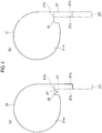
- the new knowledge is that in a case where an annular concave part 37 is formed to be depressed to an inside in a radial direction in a boundary (a boundary part) 35 between a shroud-side wall surface 27s of a diffuser 27 and a wall surface 31w of a scroll 31 (refer to Fig. 4(a) ), compared with a case where the annular concave part 37 is not formed (refer to Fig.
- a part of a low pressure part LP due to flow separation enters an inside of the annular concave part 37 in an outlet 27o side of the diffuser 27 in the shroud-side wall surface 27s during operation of a centrifugal compressor as shown in Figs. 5(a) and 5(b) , and thereby the low pressure part LP can be kept away from a flow of a main flow (a flow center line of the main flow) in the diffuser 27 and the scroll 31.
- a symbol 27i in Figs. 4(a) and 4(b) denotes an inlet of the diffuser 27 that communicates with a housing chamber (refer to Fig. 1 ) of a wheel (an impeller) 13.
- the concave part 37 need not be a continuous annular shape and, for example, the concave part may be provided only in a particular region in a peripheral direction where the low pressure part LP remarkably appears. However, machining becomes easy when the concave part 37 is formed annularly.
- Fig. 4 (a) is a schematic view showing a configuration around the diffuser 27 according to an inventive example.
- Fig. 4(b) is a schematic view showing a configuration around the diffuser 27 according to a comparative example.
- Figs. 5(a) and 5(b) are views each showing a region where a low pressure part is generated in an actuating region of a large flow rate side (a choke side) .
- Fig. 5 (a) shows the case of the inventive example
- Fig. 5(b) shows the case of the comparative example.
- the region where the low pressure part LP is generated is determined by CFD (Computational Fluid Dynamics) analysis.
- CFD Computational Fluid Dynamics
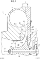
- a centrifugal compressor 1 As shown in Figs. 1 and 3 , a centrifugal compressor 1 according to the embodiment of the present invention is used for a turbocharger 3, and compresses air utilizing a centrifugal force.
- the centrifugal compressor 1 includes a housing (a compressor housing) 5.
- the housing 5 includes a housing body 7 having a shroud 7s thereinside, and a seal plate 9 provided on a right side of the housing body 7. Note that the seal plate 9 is coupled integrally with another housing (a bearing housing) 11 in the turbocharger 3.
- the wheel (the compressor wheel) 13 is rotatably provided around an axial center C thereof.
- the wheel 13 is coupled integrally with a left end of a rotation shaft 19.
- the rotation shaft 19 is rotatably provided in the another housing 11 through a plurality of thrust bearings 15 and a plurality of (only one is shown) radial bearings 17.
- the wheel 13 includes a disk 21.
- the disk 21 has a hub surface 21h.
- the hub surface 21h extends outside in a radial direction (a radial direction of the wheel 13) from a left direction (one side in an axial direction of the wheel 13).
- a plurality of blades 23 with a same axial length is integrally formed spaced apart from each other in a peripheral direction.
- a tip edge 23t of each blade 23 extends along the shroud 7s of the housing body 7. Note that plural types of blades (illustration is omitted) with different axial lengths may be used instead of using the plurality of blades 23 with the same axial length.
- An introducing port (an introducing flow passage) 25 is formed on an inlet side of the wheel 13 in the housing body 7.
- the introducing port 25 introduces air into the housing 5.
- the introducing port 25 is connected to an air cleaner (illustration is omitted) that purifies the air.
- the diffuser (a diffuser flow passage) 27 is formed on an outlet side of the wheel 13 in the housing 5.
- the diffuser 27 decreases a velocity of compressed air (compression air) to thereby raise a pressure thereof.
- the diffuser 27 is, for example, formed annularly.
- a throttle part (a throttle flow passage) 29 is formed between the wheel 13 and the diffuser 27 in the housing 5.
- a flow passage width of the throttle part 29 becomes gradually smaller along the flow direction of the main flow.
- the throttle part 29 is, for example, formed annularly.
- the throttle part 29 communicates with the diffuser 27.
- the scroll (the scroll flow passage) 31 is formed on an outlet side of the diffuser 27 in the housing 5.
- the scroll 31 is formed spirally.
- the scroll 31 communicates with the diffuser 27.
- a cross-sectional area of a winding end side (a downstream side) of the scroll 31 is larger than that of a winding start side (an upstream side) thereof.
- a discharge port (a discharge flow passage) 33 is formed in an appropriate position of the housing body 7.
- the discharge port 33 discharges compressed air outside the housing 5.
- the discharge port 33 communicates with the scroll 31, and is connected to an intake pipe (illustration is omitted) of an engine side, such as an intake manifold or an intercooler of an engine.
- the shroud-side wall surface 27s and the hub-side wall surface 27h of the diffuser 27 are parallel to the radial direction (radial direction of the wheel 13), respectively.
- the shroud-side wall surface 27s means a wall surface located on a side of a surface in which the shroud 7s of the housing body 7 has extended outside in the radial direction.
- the hub-side wall surface 27h means a wall surface located on a side of a surface in which the hub surface 21h of the disk 21 has extended outside in the radial direction.
- the annular concave part 37 is formed in the boundary (boundary part) 35 between the shroud-side wall surface 27s of the diffuser 27 and the wall surface 31w of the scroll 31.
- the concave part 37 is depressed to the inside in the radial direction.
- the low pressure part LP due to flow separation (a separation vortex) is generated on the outlet 27o side of the diffuser 27 in the shroud-side wall surface 27s.
- the concave part 37 allows a part of the low pressure part LP to enter it.
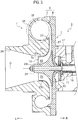
- a cross-sectional shape of the concave part 37 shown in Fig. 2(a) exhibits a V shape
- the cross-sectional shape of the concave part 37 is not limited to this.
- the cross-sectional shape of the concave part 37 is appropriately changed, for example, exhibiting a U shape as shown in Fig. 2 (b) or exhibiting a rectangular shape as shown in Fig. 2 (c) . Further, as long as the annular concave part 37 is formed to be depressed to the inside in the radial direction, a cross-sectional center line of the concave part 37 may incline in the radial direction.
- An opening width (an inlet width) ⁇ of the concave part 37 is set to be 20 to 80% of a flow passage width ⁇ of an outlet of the diffuser 27, and is preferably set to be 40 to 70% (0.20 to 0.80 times, and preferably, 0.40 to 0.70 times) . It is because if the opening width ⁇ of the concave part 37 is less than 20% of the flow passage width ⁇ , it might be small, and the part of the low pressure part LP might be difficult to enter an inside of the concave part 37 that the opening width ⁇ is set to be not less than 20% of the flow passage width ⁇ .
- the opening width ⁇ exceeds 80% of the flow passage width ⁇ of the outlet of the diffuser 27
- a part of the flow of the main flow in the scroll 31 enters the inside of the concave part 37
- the pressure difference between the inside of the scroll 31 and the concave part 37 becomes small, and as a result, the part of the low pressure part LP might be difficult to enter the inside of the concave part 37 that the opening width ⁇ is set to be not more than 80% of the flow passage width ⁇ of the outlet of the diffuser 27.
- a depression amount ⁇ of the concave part 37 is set to be 0.5 to 5.0 times of the opening width ⁇ of the concave part 37, and is preferably set to be 2.0 to 3.0 times thereof. It is because if the depression amount ⁇ is less than 0.5 times of the opening width ⁇ , it might be difficult to keep the low pressure part LP away from the flow of the main flow (the flow center line of the main flow) in the diffuser 27 and the scroll 31, even if the part of the low pressure part LP enters the inside of the concave part 37 that the depression amount ⁇ is set to be not less than 0.5 times of the opening width ⁇ .
- the depression amount ⁇ exceeds 5.0 times of the opening width ⁇ , the part of the flow of the main flow in the scroll 31 flows into the concave part 37, a stagnation pressure of a bottom side of the concave part 37 increases, and thereby the part of the low pressure part LP might be difficult to enter the inside of the concave part 37 that the depression amount ⁇ is set to be not more than 5.0 times of the opening width ⁇ .
- the wheel 13 is rotated integrally with the rotation shaft 19 around the axial center thereof by drive of a radial turbine (illustration is omitted) in the turbocharger 3, and thereby air introduced into the housing 5 from the introducing port 25 can be compressed.
- a pressure of the compressed air (compression air) is then raised, while a velocity thereof is decreased by the diffuser 27, and the compressed air whose pressure has been raised is discharged outside the housing 5 from the discharge port 33 via the scroll 31.
- the annular concave part 37 is formed to be depressed to the inside in the radial direction in the boundary 35 between the shroud-side wall surface 27s of the diffuser 27 and the wall surface 31w of the scroll 31. Therefore, when the above-mentioned new knowledge is applied, the part of the low pressure part LP due to the flow separation (separation vortex) in the outlet 27o side of the diffuser 27 in the shroud-side wall surface 27s enters the inside of the annular concave part 37 during operation of the centrifugal compressor 1 (during operation of the turbocharger 3). As a result, the low pressure part LP can be kept away from the flow of the main flow (the flow center line of the main flow) in the diffuser 27 and the scroll 31. In other words, the low pressure part LP can be displaced to a point that does not prevent the flow of the main flow in the diffuser 27 and the scroll 31.
- the low pressure part LP due to the flow separation of the outlet 27o side of the diffuser 27 in the shroud-side wall surface 27s can be kept away from the flow of the main flow in the diffuser 27 during operation of the centrifugal compressor 1. Therefore, decrease of an effective flow passage area of the outlet 27o side of the diffuser 27 can be suppressed. Accordingly, a velocity of the flow of the main flow can be sufficiently decreased by the diffuser 27.
- the separation of the low pressure part LP due to the flow separation of the outlet 27o side of the diffuser 27 in the shroud-side wall surface 27s can be kept away from the flow of the main flow in the scroll 31.
- collision (interference) of the low pressure part LP and the flow of the main flow in the scroll 31 can be lessened to thereby suppress turbulence of the flow of the main flow in the discharge port 33 located on a downstream side of the scroll 31. Consequently, according to the present invention, improvement in compressor efficiency of the centrifugal compressor 1 can be achieved, while enhancing static pressure recovery performance of the diffuser 27.
- the present invention is not limited to the above-mentioned explanation of the embodiment, and that it can be carried out in other various aspects within the scope of the appended claims, such as arranging a plurality of diffuser vanes (illustration is omitted) spaced apart from each other in a peripheral direction in the diffuser 27.
- the scope of right encompassed in the present invention is not limited to these embodiments, but defined in the appended claims.
Landscapes
- Engineering & Computer Science (AREA)
- Mechanical Engineering (AREA)
- General Engineering & Computer Science (AREA)
- Chemical & Material Sciences (AREA)
- Combustion & Propulsion (AREA)
- Structures Of Non-Positive Displacement Pumps (AREA)
- Supercharger (AREA)
Applications Claiming Priority (2)
| Application Number | Priority Date | Filing Date | Title |
|---|---|---|---|
| JP2013162985 | 2013-08-06 | ||
| PCT/JP2014/070024 WO2015019909A1 (ja) | 2013-08-06 | 2014-07-30 | 遠心圧縮機及び過給機 |
Publications (3)
| Publication Number | Publication Date |
|---|---|
| EP3032109A1 EP3032109A1 (en) | 2016-06-15 |
| EP3032109A4 EP3032109A4 (en) | 2016-08-17 |
| EP3032109B1 true EP3032109B1 (en) | 2018-06-13 |
Family
ID=52461247
Family Applications (1)
| Application Number | Title | Priority Date | Filing Date |
|---|---|---|---|
| EP14834821.2A Active EP3032109B1 (en) | 2013-08-06 | 2014-07-30 | Centrifugal compressor and supercharger |
Country Status (5)
| Country | Link |
|---|---|
| US (1) | US10138898B2 (ja) |
| EP (1) | EP3032109B1 (ja) |
| JP (1) | JP6119862B2 (ja) |
| CN (1) | CN105283674B (ja) |
| WO (1) | WO2015019909A1 (ja) |
Families Citing this family (5)
| Publication number | Priority date | Publication date | Assignee | Title |
|---|---|---|---|---|
| CN108700090B (zh) * | 2016-03-30 | 2020-05-15 | 三菱重工发动机和增压器株式会社 | 压缩机涡旋及离心压缩机 |
| JPWO2018174166A1 (ja) * | 2017-03-24 | 2019-06-27 | 株式会社Ihi | 遠心圧縮機 |
| US20190282046A1 (en) * | 2018-03-13 | 2019-09-19 | Emerson Electric Co. | Vacuum cleaner power head including volute and vacuum cleaner including same |
| DE112019007469T5 (de) * | 2019-07-16 | 2022-03-03 | Mitsubishi Heavy Industries Engine & Turbocharger, Ltd. | Schneckenstruktur eines Zentrifugalverdichters und ein Zentrifugalverdichter |
| US20230093314A1 (en) * | 2021-09-17 | 2023-03-23 | Carrier Corporation | Passive flow reversal reduction in compressor assembly |
Citations (1)
| Publication number | Priority date | Publication date | Assignee | Title |
|---|---|---|---|---|
| US20120171030A1 (en) * | 2009-09-16 | 2012-07-05 | Mitsubishi Heavy Industries, Ltd. | Discharge scroll and turbomachine |
Family Cites Families (20)
| Publication number | Priority date | Publication date | Assignee | Title |
|---|---|---|---|---|
| FR999797A (fr) * | 1946-01-04 | 1952-02-05 | Rateau Soc | Perfectionnement aux pompes et compresseurs centrifuges |
| DE4125487C1 (en) * | 1991-08-01 | 1992-06-17 | Mtu Friedrichshafen Gmbh | Flow casing for radial-flow compressor - has side duct in restricted peripheral section in narrow region of spiral cross=section |
| DE4331606C1 (de) * | 1993-09-17 | 1994-10-06 | Gutehoffnungshuette Man | Spiralgehäuse für Turbomaschinen |
| JPH09280196A (ja) | 1996-04-11 | 1997-10-28 | Daikin Ind Ltd | 送風機 |
| CN1213237C (zh) * | 2002-05-31 | 2005-08-03 | 乐金电子(天津)电器有限公司 | 涡轮压缩机的扩散器结构 |
| JP4146371B2 (ja) | 2004-02-27 | 2008-09-10 | 三菱重工業株式会社 | 遠心圧縮機 |
| JP4275081B2 (ja) | 2005-02-10 | 2009-06-10 | 三菱重工業株式会社 | 可変容量型排気ターボ過給機のスクロール構造及びその製造方法 |
| US20070196206A1 (en) * | 2006-02-17 | 2007-08-23 | Honeywell International, Inc. | Pressure load compressor diffuser |
| JP2008075536A (ja) * | 2006-09-21 | 2008-04-03 | Mitsubishi Heavy Ind Ltd | 遠心圧縮機 |
| JP4853263B2 (ja) | 2006-12-07 | 2012-01-11 | 株式会社豊田自動織機 | 遠心圧縮機 |
| JP5029024B2 (ja) * | 2007-01-18 | 2012-09-19 | 株式会社Ihi | 遠心圧縮機 |
| DE102007019264A1 (de) * | 2007-04-24 | 2008-11-06 | Man Turbo Ag | Filtervorrichtung |
| JP2009002305A (ja) * | 2007-06-25 | 2009-01-08 | Toyota Motor Corp | 過給機 |
| US8070416B2 (en) * | 2008-03-27 | 2011-12-06 | International Engine Intellectual Property Company, Llc | Flow regulation mechanism for turbocharger compressor |
| CN102066717A (zh) * | 2008-06-17 | 2011-05-18 | 株式会社Ihi | 涡轮增压机用的压缩机壳体 |
| JP2010196542A (ja) | 2009-02-24 | 2010-09-09 | Toyota Motor Corp | 遠心圧縮機、及びターボ過給機 |
| JP5832106B2 (ja) * | 2011-03-08 | 2015-12-16 | 三菱重工業株式会社 | 回転機械 |
| CN102182710B (zh) * | 2011-03-23 | 2013-07-17 | 清华大学 | 具有非对称无叶扩压器的离心压气机及其形成方法 |
| JP2012241558A (ja) | 2011-05-17 | 2012-12-10 | Ihi Corp | バイパスバルブ及び過給機 |
| US9482240B2 (en) * | 2013-07-31 | 2016-11-01 | Honeywell International Inc. | Compressor housing assembly for a turbocharger |
-
2014
- 2014-07-30 CN CN201480033384.5A patent/CN105283674B/zh active Active
- 2014-07-30 WO PCT/JP2014/070024 patent/WO2015019909A1/ja active Application Filing
- 2014-07-30 JP JP2015530835A patent/JP6119862B2/ja active Active
- 2014-07-30 EP EP14834821.2A patent/EP3032109B1/en active Active
-
2015
- 2015-12-01 US US14/955,606 patent/US10138898B2/en active Active
Patent Citations (1)
| Publication number | Priority date | Publication date | Assignee | Title |
|---|---|---|---|---|
| US20120171030A1 (en) * | 2009-09-16 | 2012-07-05 | Mitsubishi Heavy Industries, Ltd. | Discharge scroll and turbomachine |
Also Published As
| Publication number | Publication date |
|---|---|
| JP6119862B2 (ja) | 2017-04-26 |
| JPWO2015019909A1 (ja) | 2017-03-02 |
| CN105283674B (zh) | 2017-08-25 |
| CN105283674A (zh) | 2016-01-27 |
| US20160138608A1 (en) | 2016-05-19 |
| US10138898B2 (en) | 2018-11-27 |
| WO2015019909A1 (ja) | 2015-02-12 |
| EP3032109A4 (en) | 2016-08-17 |
| EP3032109A1 (en) | 2016-06-15 |
Similar Documents
| Publication | Publication Date | Title |
|---|---|---|
| EP3032108B1 (en) | Centrifugal compressor and supercharger | |
| US9874224B2 (en) | Centrifugal compressor and turbocharger | |
| US6834501B1 (en) | Turbocharger compressor with non-axisymmetric deswirl vanes | |
| US8308420B2 (en) | Centrifugal compressor, impeller and operating method of the same | |
| EP3032109B1 (en) | Centrifugal compressor and supercharger | |
| EP2960528B1 (en) | Centrifugal compressor | |
| EP3018355B1 (en) | Adjustable-trim centrifugal compressor, and turbocharger having same | |
| EP2169238B1 (en) | Centrifugal compressor | |
| US10330102B2 (en) | Centrifugal compressor and turbocharger | |
| EP2789861A1 (en) | Centrifugal fluid machine | |
| WO2013008599A1 (ja) | 遠心圧縮機 | |
| CN105782073A (zh) | 多级径向压缩机挡板 | |
| CN107110178B (zh) | 用于径向压缩机的扩散器 | |
| EP3599344A1 (en) | Systems for turbine engine particle separation | |
| WO2018155546A1 (ja) | 遠心圧縮機 | |
| US20120183395A1 (en) | Radial compressor diffuser | |
| US11187242B2 (en) | Multi-stage centrifugal compressor | |
| CN112576321A (zh) | 废气涡轮增压器的涡轮的流出区域 | |
| JP2012177357A (ja) | ラジアルタービン及び過給機 | |
| CN106662119B (zh) | 用于涡轮机的改进的涡管、包括所述涡管的涡轮机和操作的方法 | |
| JP2015040505A (ja) | 遠心圧縮機及び過給機 | |
| JP7123029B2 (ja) | 遠心圧縮機 |
Legal Events
| Date | Code | Title | Description |
|---|---|---|---|
| PUAI | Public reference made under article 153(3) epc to a published international application that has entered the european phase |
Free format text: ORIGINAL CODE: 0009012 |
|
| 17P | Request for examination filed |
Effective date: 20151209 |
|
| AK | Designated contracting states |
Kind code of ref document: A1 Designated state(s): AL AT BE BG CH CY CZ DE DK EE ES FI FR GB GR HR HU IE IS IT LI LT LU LV MC MK MT NL NO PL PT RO RS SE SI SK SM TR |
|
| AX | Request for extension of the european patent |
Extension state: BA ME |
|
| A4 | Supplementary search report drawn up and despatched |
Effective date: 20160719 |
|
| RIC1 | Information provided on ipc code assigned before grant |
Ipc: F04D 17/10 20060101ALI20160713BHEP Ipc: F04D 29/44 20060101AFI20160713BHEP Ipc: F04D 29/68 20060101ALI20160713BHEP |
|
| DAX | Request for extension of the european patent (deleted) | ||
| GRAP | Despatch of communication of intention to grant a patent |
Free format text: ORIGINAL CODE: EPIDOSNIGR1 |
|
| RIC1 | Information provided on ipc code assigned before grant |
Ipc: F04D 29/68 20060101ALI20171205BHEP Ipc: F04D 29/44 20060101AFI20171205BHEP Ipc: F04D 17/10 20060101ALI20171205BHEP Ipc: F02B 33/40 20060101ALI20171205BHEP |
|
| INTG | Intention to grant announced |
Effective date: 20180102 |
|
| GRAS | Grant fee paid |
Free format text: ORIGINAL CODE: EPIDOSNIGR3 |
|
| GRAA | (expected) grant |
Free format text: ORIGINAL CODE: 0009210 |
|
| AK | Designated contracting states |
Kind code of ref document: B1 Designated state(s): AL AT BE BG CH CY CZ DE DK EE ES FI FR GB GR HR HU IE IS IT LI LT LU LV MC MK MT NL NO PL PT RO RS SE SI SK SM TR |
|
| REG | Reference to a national code |
Ref country code: GB Ref legal event code: FG4D |
|
| REG | Reference to a national code |
Ref country code: CH Ref legal event code: EP Ref country code: AT Ref legal event code: REF Ref document number: 1008802 Country of ref document: AT Kind code of ref document: T Effective date: 20180615 |
|
| REG | Reference to a national code |
Ref country code: IE Ref legal event code: FG4D |
|
| REG | Reference to a national code |
Ref country code: DE Ref legal event code: R096 Ref document number: 602014027124 Country of ref document: DE |
|
| REG | Reference to a national code |
Ref country code: NL Ref legal event code: MP Effective date: 20180613 |
|
| REG | Reference to a national code |
Ref country code: LT Ref legal event code: MG4D |
|
| PG25 | Lapsed in a contracting state [announced via postgrant information from national office to epo] |
Ref country code: ES Free format text: LAPSE BECAUSE OF FAILURE TO SUBMIT A TRANSLATION OF THE DESCRIPTION OR TO PAY THE FEE WITHIN THE PRESCRIBED TIME-LIMIT Effective date: 20180613 Ref country code: SE Free format text: LAPSE BECAUSE OF FAILURE TO SUBMIT A TRANSLATION OF THE DESCRIPTION OR TO PAY THE FEE WITHIN THE PRESCRIBED TIME-LIMIT Effective date: 20180613 Ref country code: NO Free format text: LAPSE BECAUSE OF FAILURE TO SUBMIT A TRANSLATION OF THE DESCRIPTION OR TO PAY THE FEE WITHIN THE PRESCRIBED TIME-LIMIT Effective date: 20180913 Ref country code: FI Free format text: LAPSE BECAUSE OF FAILURE TO SUBMIT A TRANSLATION OF THE DESCRIPTION OR TO PAY THE FEE WITHIN THE PRESCRIBED TIME-LIMIT Effective date: 20180613 Ref country code: BG Free format text: LAPSE BECAUSE OF FAILURE TO SUBMIT A TRANSLATION OF THE DESCRIPTION OR TO PAY THE FEE WITHIN THE PRESCRIBED TIME-LIMIT Effective date: 20180913 Ref country code: LT Free format text: LAPSE BECAUSE OF FAILURE TO SUBMIT A TRANSLATION OF THE DESCRIPTION OR TO PAY THE FEE WITHIN THE PRESCRIBED TIME-LIMIT Effective date: 20180613 Ref country code: CY Free format text: LAPSE BECAUSE OF FAILURE TO SUBMIT A TRANSLATION OF THE DESCRIPTION OR TO PAY THE FEE WITHIN THE PRESCRIBED TIME-LIMIT Effective date: 20180613 |
|
| PG25 | Lapsed in a contracting state [announced via postgrant information from national office to epo] |
Ref country code: GR Free format text: LAPSE BECAUSE OF FAILURE TO SUBMIT A TRANSLATION OF THE DESCRIPTION OR TO PAY THE FEE WITHIN THE PRESCRIBED TIME-LIMIT Effective date: 20180914 Ref country code: RS Free format text: LAPSE BECAUSE OF FAILURE TO SUBMIT A TRANSLATION OF THE DESCRIPTION OR TO PAY THE FEE WITHIN THE PRESCRIBED TIME-LIMIT Effective date: 20180613 Ref country code: HR Free format text: LAPSE BECAUSE OF FAILURE TO SUBMIT A TRANSLATION OF THE DESCRIPTION OR TO PAY THE FEE WITHIN THE PRESCRIBED TIME-LIMIT Effective date: 20180613 Ref country code: LV Free format text: LAPSE BECAUSE OF FAILURE TO SUBMIT A TRANSLATION OF THE DESCRIPTION OR TO PAY THE FEE WITHIN THE PRESCRIBED TIME-LIMIT Effective date: 20180613 |
|
| REG | Reference to a national code |
Ref country code: AT Ref legal event code: MK05 Ref document number: 1008802 Country of ref document: AT Kind code of ref document: T Effective date: 20180613 |
|
| PG25 | Lapsed in a contracting state [announced via postgrant information from national office to epo] |
Ref country code: NL Free format text: LAPSE BECAUSE OF FAILURE TO SUBMIT A TRANSLATION OF THE DESCRIPTION OR TO PAY THE FEE WITHIN THE PRESCRIBED TIME-LIMIT Effective date: 20180613 |
|
| PG25 | Lapsed in a contracting state [announced via postgrant information from national office to epo] |
Ref country code: RO Free format text: LAPSE BECAUSE OF FAILURE TO SUBMIT A TRANSLATION OF THE DESCRIPTION OR TO PAY THE FEE WITHIN THE PRESCRIBED TIME-LIMIT Effective date: 20180613 Ref country code: CZ Free format text: LAPSE BECAUSE OF FAILURE TO SUBMIT A TRANSLATION OF THE DESCRIPTION OR TO PAY THE FEE WITHIN THE PRESCRIBED TIME-LIMIT Effective date: 20180613 Ref country code: SK Free format text: LAPSE BECAUSE OF FAILURE TO SUBMIT A TRANSLATION OF THE DESCRIPTION OR TO PAY THE FEE WITHIN THE PRESCRIBED TIME-LIMIT Effective date: 20180613 Ref country code: EE Free format text: LAPSE BECAUSE OF FAILURE TO SUBMIT A TRANSLATION OF THE DESCRIPTION OR TO PAY THE FEE WITHIN THE PRESCRIBED TIME-LIMIT Effective date: 20180613 Ref country code: IS Free format text: LAPSE BECAUSE OF FAILURE TO SUBMIT A TRANSLATION OF THE DESCRIPTION OR TO PAY THE FEE WITHIN THE PRESCRIBED TIME-LIMIT Effective date: 20181013 Ref country code: AT Free format text: LAPSE BECAUSE OF FAILURE TO SUBMIT A TRANSLATION OF THE DESCRIPTION OR TO PAY THE FEE WITHIN THE PRESCRIBED TIME-LIMIT Effective date: 20180613 Ref country code: PL Free format text: LAPSE BECAUSE OF FAILURE TO SUBMIT A TRANSLATION OF THE DESCRIPTION OR TO PAY THE FEE WITHIN THE PRESCRIBED TIME-LIMIT Effective date: 20180613 |
|
| PG25 | Lapsed in a contracting state [announced via postgrant information from national office to epo] |
Ref country code: IT Free format text: LAPSE BECAUSE OF FAILURE TO SUBMIT A TRANSLATION OF THE DESCRIPTION OR TO PAY THE FEE WITHIN THE PRESCRIBED TIME-LIMIT Effective date: 20180613 Ref country code: SM Free format text: LAPSE BECAUSE OF FAILURE TO SUBMIT A TRANSLATION OF THE DESCRIPTION OR TO PAY THE FEE WITHIN THE PRESCRIBED TIME-LIMIT Effective date: 20180613 |
|
| REG | Reference to a national code |
Ref country code: CH Ref legal event code: PL |
|
| REG | Reference to a national code |
Ref country code: DE Ref legal event code: R097 Ref document number: 602014027124 Country of ref document: DE |
|
| PG25 | Lapsed in a contracting state [announced via postgrant information from national office to epo] |
Ref country code: MC Free format text: LAPSE BECAUSE OF FAILURE TO SUBMIT A TRANSLATION OF THE DESCRIPTION OR TO PAY THE FEE WITHIN THE PRESCRIBED TIME-LIMIT Effective date: 20180613 Ref country code: LU Free format text: LAPSE BECAUSE OF NON-PAYMENT OF DUE FEES Effective date: 20180730 |
|
| REG | Reference to a national code |
Ref country code: BE Ref legal event code: MM Effective date: 20180731 |
|
| PLBE | No opposition filed within time limit |
Free format text: ORIGINAL CODE: 0009261 |
|
| STAA | Information on the status of an ep patent application or granted ep patent |
Free format text: STATUS: NO OPPOSITION FILED WITHIN TIME LIMIT |
|
| PG25 | Lapsed in a contracting state [announced via postgrant information from national office to epo] |
Ref country code: LI Free format text: LAPSE BECAUSE OF NON-PAYMENT OF DUE FEES Effective date: 20180731 Ref country code: CH Free format text: LAPSE BECAUSE OF NON-PAYMENT OF DUE FEES Effective date: 20180731 |
|
| REG | Reference to a national code |
Ref country code: IE Ref legal event code: MM4A |
|
| 26N | No opposition filed |
Effective date: 20190314 |
|
| GBPC | Gb: european patent ceased through non-payment of renewal fee |
Effective date: 20180913 |
|
| PG25 | Lapsed in a contracting state [announced via postgrant information from national office to epo] |
Ref country code: DK Free format text: LAPSE BECAUSE OF FAILURE TO SUBMIT A TRANSLATION OF THE DESCRIPTION OR TO PAY THE FEE WITHIN THE PRESCRIBED TIME-LIMIT Effective date: 20180613 Ref country code: BE Free format text: LAPSE BECAUSE OF NON-PAYMENT OF DUE FEES Effective date: 20180731 Ref country code: SI Free format text: LAPSE BECAUSE OF FAILURE TO SUBMIT A TRANSLATION OF THE DESCRIPTION OR TO PAY THE FEE WITHIN THE PRESCRIBED TIME-LIMIT Effective date: 20180613 |
|
| PG25 | Lapsed in a contracting state [announced via postgrant information from national office to epo] |
Ref country code: IE Free format text: LAPSE BECAUSE OF NON-PAYMENT OF DUE FEES Effective date: 20180730 |
|
| PG25 | Lapsed in a contracting state [announced via postgrant information from national office to epo] |
Ref country code: FR Free format text: LAPSE BECAUSE OF NON-PAYMENT OF DUE FEES Effective date: 20180813 |
|
| PG25 | Lapsed in a contracting state [announced via postgrant information from national office to epo] |
Ref country code: GB Free format text: LAPSE BECAUSE OF NON-PAYMENT OF DUE FEES Effective date: 20180913 |
|
| PG25 | Lapsed in a contracting state [announced via postgrant information from national office to epo] |
Ref country code: AL Free format text: LAPSE BECAUSE OF FAILURE TO SUBMIT A TRANSLATION OF THE DESCRIPTION OR TO PAY THE FEE WITHIN THE PRESCRIBED TIME-LIMIT Effective date: 20180613 |
|
| PG25 | Lapsed in a contracting state [announced via postgrant information from national office to epo] |
Ref country code: MT Free format text: LAPSE BECAUSE OF NON-PAYMENT OF DUE FEES Effective date: 20180730 |
|
| PG25 | Lapsed in a contracting state [announced via postgrant information from national office to epo] |
Ref country code: TR Free format text: LAPSE BECAUSE OF FAILURE TO SUBMIT A TRANSLATION OF THE DESCRIPTION OR TO PAY THE FEE WITHIN THE PRESCRIBED TIME-LIMIT Effective date: 20180613 |
|
| PG25 | Lapsed in a contracting state [announced via postgrant information from national office to epo] |
Ref country code: PT Free format text: LAPSE BECAUSE OF FAILURE TO SUBMIT A TRANSLATION OF THE DESCRIPTION OR TO PAY THE FEE WITHIN THE PRESCRIBED TIME-LIMIT Effective date: 20180613 |
|
| PG25 | Lapsed in a contracting state [announced via postgrant information from national office to epo] |
Ref country code: HU Free format text: LAPSE BECAUSE OF FAILURE TO SUBMIT A TRANSLATION OF THE DESCRIPTION OR TO PAY THE FEE WITHIN THE PRESCRIBED TIME-LIMIT; INVALID AB INITIO Effective date: 20140730 Ref country code: MK Free format text: LAPSE BECAUSE OF NON-PAYMENT OF DUE FEES Effective date: 20180613 |
|
| PGFP | Annual fee paid to national office [announced via postgrant information from national office to epo] |
Ref country code: DE Payment date: 20230620 Year of fee payment: 10 |