EP3031991A1 - Dispositif d'appui - Google Patents
Dispositif d'appui Download PDFInfo
- Publication number
- EP3031991A1 EP3031991A1 EP15198689.0A EP15198689A EP3031991A1 EP 3031991 A1 EP3031991 A1 EP 3031991A1 EP 15198689 A EP15198689 A EP 15198689A EP 3031991 A1 EP3031991 A1 EP 3031991A1
- Authority
- EP
- European Patent Office
- Prior art keywords
- housing
- support
- shape memory
- memory element
- hand
- Prior art date
- Legal status (The legal status is an assumption and is not a legal conclusion. Google has not performed a legal analysis and makes no representation as to the accuracy of the status listed.)
- Granted
Links
- 238000007689 inspection Methods 0.000 claims abstract description 49
- 238000004140 cleaning Methods 0.000 claims abstract description 33
- 230000008859 change Effects 0.000 claims abstract description 14
- 230000001105 regulatory effect Effects 0.000 claims description 17
- 239000000463 material Substances 0.000 claims description 12
- 229920003023 plastic Polymers 0.000 claims description 3
- 241000826860 Trapezium Species 0.000 claims description 2
- 230000006870 function Effects 0.000 abstract description 5
- 230000007935 neutral effect Effects 0.000 description 23
- 238000012423 maintenance Methods 0.000 description 12
- 238000003825 pressing Methods 0.000 description 11
- 230000003213 activating effect Effects 0.000 description 5
- 230000008901 benefit Effects 0.000 description 5
- 230000009849 deactivation Effects 0.000 description 5
- 238000010438 heat treatment Methods 0.000 description 5
- -1 copper-zinc-aluminum Chemical compound 0.000 description 3
- 230000001419 dependent effect Effects 0.000 description 3
- 230000007423 decrease Effects 0.000 description 2
- 238000011161 development Methods 0.000 description 2
- 230000018109 developmental process Effects 0.000 description 2
- 230000000694 effects Effects 0.000 description 2
- 238000003801 milling Methods 0.000 description 2
- 239000012781 shape memory material Substances 0.000 description 2
- 229910001285 shape-memory alloy Inorganic materials 0.000 description 2
- 238000004904 shortening Methods 0.000 description 2
- XUIMIQQOPSSXEZ-UHFFFAOYSA-N Silicon Chemical compound [Si] XUIMIQQOPSSXEZ-UHFFFAOYSA-N 0.000 description 1
- SXKZZFLSYPUIAN-UHFFFAOYSA-N [Cu].[Zn].[Au] Chemical compound [Cu].[Zn].[Au] SXKZZFLSYPUIAN-UHFFFAOYSA-N 0.000 description 1
- HZEWFHLRYVTOIW-UHFFFAOYSA-N [Ti].[Ni] Chemical compound [Ti].[Ni] HZEWFHLRYVTOIW-UHFFFAOYSA-N 0.000 description 1
- WCERXPKXJMFQNQ-UHFFFAOYSA-N [Ti].[Ni].[Cu] Chemical compound [Ti].[Ni].[Cu] WCERXPKXJMFQNQ-UHFFFAOYSA-N 0.000 description 1
- 238000005299 abrasion Methods 0.000 description 1
- 239000003795 chemical substances by application Substances 0.000 description 1
- 230000006835 compression Effects 0.000 description 1
- 238000007906 compression Methods 0.000 description 1
- 238000001816 cooling Methods 0.000 description 1
- TVZPLCNGKSPOJA-UHFFFAOYSA-N copper zinc Chemical compound [Cu].[Zn] TVZPLCNGKSPOJA-UHFFFAOYSA-N 0.000 description 1
- 230000008878 coupling Effects 0.000 description 1
- 238000010168 coupling process Methods 0.000 description 1
- 238000005859 coupling reaction Methods 0.000 description 1
- 238000005553 drilling Methods 0.000 description 1
- 238000000605 extraction Methods 0.000 description 1
- 229920002457 flexible plastic Polymers 0.000 description 1
- 239000007789 gas Substances 0.000 description 1
- 239000010720 hydraulic oil Substances 0.000 description 1
- 230000001939 inductive effect Effects 0.000 description 1
- DALUDRGQOYMVLD-UHFFFAOYSA-N iron manganese Chemical compound [Mn].[Fe] DALUDRGQOYMVLD-UHFFFAOYSA-N 0.000 description 1
- 239000007788 liquid Substances 0.000 description 1
- 229910001000 nickel titanium Inorganic materials 0.000 description 1
- 230000003287 optical effect Effects 0.000 description 1
- 238000010926 purge Methods 0.000 description 1
- 230000009467 reduction Effects 0.000 description 1
- 229920000431 shape-memory polymer Polymers 0.000 description 1
- 229910052710 silicon Inorganic materials 0.000 description 1
- 239000010703 silicon Substances 0.000 description 1
Images


Classifications
-
- E—FIXED CONSTRUCTIONS
- E03—WATER SUPPLY; SEWERAGE
- E03F—SEWERS; CESSPOOLS
- E03F7/00—Other installations or implements for operating sewer systems, e.g. for preventing or indicating stoppage; Emptying cesspools
- E03F7/12—Installations enabling inspection personnel to drive along sewer canals
-
- E—FIXED CONSTRUCTIONS
- E03—WATER SUPPLY; SEWERAGE
- E03F—SEWERS; CESSPOOLS
- E03F9/00—Arrangements or fixed installations methods or devices for cleaning or clearing sewer pipes, e.g. by flushing
- E03F9/002—Cleaning sewer pipes by mechanical means
-
- F—MECHANICAL ENGINEERING; LIGHTING; HEATING; WEAPONS; BLASTING
- F16—ENGINEERING ELEMENTS AND UNITS; GENERAL MEASURES FOR PRODUCING AND MAINTAINING EFFECTIVE FUNCTIONING OF MACHINES OR INSTALLATIONS; THERMAL INSULATION IN GENERAL
- F16L—PIPES; JOINTS OR FITTINGS FOR PIPES; SUPPORTS FOR PIPES, CABLES OR PROTECTIVE TUBING; MEANS FOR THERMAL INSULATION IN GENERAL
- F16L55/00—Devices or appurtenances for use in, or in connection with, pipes or pipe systems
- F16L55/18—Appliances for use in repairing pipes
-
- F—MECHANICAL ENGINEERING; LIGHTING; HEATING; WEAPONS; BLASTING
- F16—ENGINEERING ELEMENTS AND UNITS; GENERAL MEASURES FOR PRODUCING AND MAINTAINING EFFECTIVE FUNCTIONING OF MACHINES OR INSTALLATIONS; THERMAL INSULATION IN GENERAL
- F16L—PIPES; JOINTS OR FITTINGS FOR PIPES; SUPPORTS FOR PIPES, CABLES OR PROTECTIVE TUBING; MEANS FOR THERMAL INSULATION IN GENERAL
- F16L55/00—Devices or appurtenances for use in, or in connection with, pipes or pipe systems
- F16L55/26—Pigs or moles, i.e. devices movable in a pipe or conduit with or without self-contained propulsion means
- F16L55/28—Constructional aspects
- F16L55/40—Constructional aspects of the body
- F16L55/44—Constructional aspects of the body expandable
Definitions
- the invention relates to a supporting device, in particular for an inspection system and / or cleaning system for supporting the inspection and / or cleaning system on a wall or for clamping the inspection and / or cleaning system in a pipe, as well as an inspection and / or cleaning system, in particular Kanalinspektions- and / or cleaning system with a supporting device according to the invention.
- sewer inspection and / or maintenance systems systems which can be introduced into the pipe or sewer pipe to be inspected or maintained and moved in the sewer pipe , can be moved or advanced.
- supporting devices can be provided on the system with which the system can be supported on a tube inner wall or braced in the tube interior.
- Fig. 1 shows a sewer inspection system in which a plurality of support devices are provided, each support device comprises pneumatically / hydraulically / electrically actuated telescopic arms, on each of which a contact pressure means 2a is arranged.
- the telescopic arms can be extended to push the pressing means against the inner wall.
- the supporting devices have a high overall weight, so that correspondingly strong drive motors must be provided for the propulsion of the sewer inspection system.
- sliding systems which do not have their own drive and are advanced by about a semi-flexible shift cable 60, this weight can complicate the feed or even prevent.
- pneumatically / hydraulically operated telescopic arms must be regularly maintained, which can have a negative effect on the operating and maintenance costs.
- Another disadvantage is that extended telescopic arms can not automatically return to the starting position when interrupting a power supply, so that a tensioned in the pipe system can not be pulled out of the pipe at a power interruption without damaging the outriggers.
- precautions can be taken that retract the support devices in case of interruption of the power supply.
- Fig. 2 shows a channel maintenance system having an upper and a lower carriage. Between the two carriages an air cushion is arranged, which can be acted upon with compressed air to lift the upper carriage until the wheels of the upper carriage are pressed against the pipe inner wall.
- this solution has the disadvantage that the air cushion even in the folded state, as shown in Figure (a) of the Fig. 2 shown occupies a lot of space relative to the entire system, which makes the use of such systems in small diameter pipes almost impossible.
- the air cushion especially in the harsh environment of sewers, easily damaged.
- additional precautions must be taken here in order to be able to discharge the air from the air cushion in case of interruption of the power supply.
- the invention is therefore based on the object at least partially to avoid the disadvantages mentioned above and provide solutions with which inspection and / or cleaning systems supported in a pipe and / or in a cavity, in particular pipe, can be braced without the Total weight of the inspection and / or cleaning systems significantly increased, the maintenance intervals can be extended and without power supply, the inspection and / or cleaning systems can be pulled out of the pipe without damaging the outriggers.
- the actuating means or the shape memory element of the actuating means can thus be advantageously activated so that the shape of the shape memory element changes.
- the support means is deflected or raised from a neutral position (ie moved radially outward relative to the housing), so that a contact pressure means optionally arranged on the support means is also raised.
- the shape memory element of the actuating means can be deactivated again, so that the support means returns due to a restoring force of a return means or due to its own weight back to the neutral position in which the shape memory element has its original shape. This makes it possible that even with an interruption of the power supply the support means returns to its neutral position and the inspection system can be pulled out of the conduit or pipe without damaging the support means.
- the shape memory element may comprise an elongated shape memory element, in particular shape memory wire, which changes its length depending on the influencing variable, preferably reduced.
- the adjusting means may comprise a pulley, wherein the shape memory element may be part of the pulley. This has the advantage that the shape memory element for deflecting or lifting the support means must provide lower forces available, so that cost-effective shape memory elements can be used.
- the influencing variable can be the temperature of the shape memory element, wherein the temperature required for a predetermined movement of the supporting means relative to the housing can be acted upon directly or indirectly by the shape memory element. Depending on the applied temperature, it is thus possible in an advantageous manner to deflect or lift the support means by different amplitudes.
- the shape memory element may be coupled to a control and / or regulating device which is adapted to apply the shape memory element with the temperature required for a predetermined movement of the support means relative to the housing.
- the control and / or regulating device may be adapted to feed electrical current into the shape memory element or to pass it through the shape memory element in order to heat it.
- the device has at least one return means cooperating with the support means, wherein a restoring force of the return means counteracts a actuating force of the actuating means.
- the return means may comprise at least one spring element.
- the support devices can be retracted even with an interruption of the power supply.
- the shape memory elements of the adjusting means again assume their original length, so that the adjusting means do not counteract the return means.
- the adjusting means may be guided by the first fastening unit via a deflection point to the second fastening unit, wherein the adjusting means is deflected at the deflection point.
- the deflection point may comprise a deflection device, in particular at least one deflection roller.
- the second end of the lifting arm may be associated with a carriage on which the second end of the lifting arm is articulated, wherein the carriage is movable in the longitudinal or transverse direction to the housing and wherein the adjusting means is coupled to the carriage.
- the support means can be arranged linearly relative to the housing movable, preferably in the radial direction perpendicular to the longitudinal axis or transverse axis of the housing, on the housing.
- the side wall of the housing is designed to be flexible, in particular its extent is variable in the longitudinal direction.
- a circuit board may be arranged, which has the control and / or regulating device.
- a contact pressure may be arranged on the free end of the support means a contact pressure. It is advantageous if the pressing means is pivotable about a pivot axis relative to the support means.
- the pressing means may comprise a slip-resistant material, in particular a plastic.
- the pressing means may comprise a wheel.
- the support device has a temperature sensor, wherein the control and / or regulating device is adapted to act on the shape memory element with the required temperature depending on a measured ambient temperature.
- the support device has a force sensor, with which the tensile force of the actuating means and / or the contact pressure of the support means or the Anpressstoffs is measurable, the control and / or regulating device is adjusted, depending on a measured tensile force and / or Contact pressure to pressurize the shape memory element with the required temperature.
- the force sensor can also be avoided that the shape memory element acted upon current is limited to avoid damage to the actuating means, the shape memory element or the entire support device.
- the support device may be detachably attachable to an inspection and / or cleaning system.
- the support device can be provided as a support module.
- the housing may be a housing of the inspection and / or cleaning system.
- the invention further provides an inspection system and / or cleaning system, in particular a duct inspection and / or cleaning system, which has a supporting device according to the invention.
- the inspection system and / or cleaning system can have working means, in particular tools, wherein the working means can be arranged with the support device in the center of the pipe.
- the inspection system and / or cleaning system can be braced with the support device in a pipe.
- the inspection system and / or cleaning system can be stabilized in an advantageous manner, so that on the one hand maintenance can be performed precisely and on the other hand vibrations of the system during maintenance are reduced.
- the invention provides a support module which has a support device according to the invention, wherein the support module has connection means for the connection of data and / or power cables, and wherein the support module has a fastening device for fastening the support module to an inspection system.
- any inspection system can be retrofitted or upgraded with a support module.
- Fig. 3 shows a first embodiment of a support device 2 according to the invention for an inspection system and / or cleaning system, wherein in Figure (a) the support device in a neutral position and in Figure (b) the support device is shown in a working position.
- the supporting device 2 has a supporting means 2b, a pressing means 2a arranged on the supporting means 2b and an adjusting device.
- the Support device 2 is arranged on a housing 4. On the housing 4 a plurality of supporting devices 2 according to the invention can be arranged.
- the housing 4 may be the housing of a support module, which may be mounted on an inspection system, such as a trolley, or on a working means of an inspection system.
- the housing 4 can have connection means for connecting data and / or power cables.
- the housing may have fastening devices in order to fasten the support module to the inspection system.
- the support means 2b which is designed here as an arm, is articulated via a pivot axis 5 on the housing 4 and can be pivoted relative to the housing 4 from a basic position or neutral position upwards into a working position.
- a neutral position of the support device 2 is shown in Figure (a).
- a working position of the supporting device 2 is shown in Figure (b), wherein a pressing means 2a is pressed against a pipe inner wall 1.
- a contact pressure means 2a is pivotally mounted on the support means 2b.
- the supporting device 2 has an adjusting means, which cooperates with the supporting means 2b.
- the adjusting means is provided to the support means 2b from a neutral position against a restoring force of an in Fig. 1 not shown return means (eg a return spring) to deflect or to swing upwards.
- return means eg a return spring
- the adjusting means has a shape memory element 20, which is designed here as an elongated shape memory wire.
- the adjusting means here additionally tensile elements 21, which here in each case with the shape memory element 20 and with a first attachment unit 12 or with a second fastening unit 12b are connected.
- the first attachment unit 12 is fixedly secured to the housing and the second attachment unit 12b is attached to the support means 2b.
- tension members 21, for example, wires, ropes or the like can be used. It is advantageous if the tension elements 21 do not change their length when subjected to a tensile force.
- the tension elements 21 can also be dispensed with and the shape memory wire 20 can be fastened directly to the two fastening units 12, 12b.
- the adjusting means (here the tension element 21 of the actuating means) is guided over the deflection point 23 as a deflection point from the first fastening unit 12 to the second fastening unit 12b, wherein the adjusting means is deflected at the deflection roller 23.
- the adjusting means runs between the deflection roller 23 and the second fastening unit 12b substantially parallel to the longitudinal axis of the supporting means 2b.
- the portion of the adjusting means associated with the supporting means 2b and the second fastening unit 12b are arranged inside or in tubular-shaped sections of the supporting means 2b.
- the adjusting means is shortened by the shape memory element 20 is acted upon by a physical quantity, which causes a change in shape of the shape memory element 20.
- the shape change of the shape memory element 20 is preferably such that when the shape memory element 20 is subjected to the physical quantity, the length of the shape memory element is reduced. Due to the reduced length of the shape memory element 20, the total length of the actuating means is reduced. By shortening the actuating means acts on the second fastening unit 12b, a tensile force, which pivots the support means 2b upwards.
- those materials are used for the shape memory element 20 which change their shape or length when the temperature changes, for example when the temperature increases.
- shape memory elements as an adjusting agent or component of the actuating means has the advantage that very high actuating forces can be achieved with very little use of material and very small space requirement. Thus, a particularly space-saving adjusting means can be provided.
- shape memory elements are subject to little or no wear, whereby the maintenance intervals for the maintenance of the supporting device 2 according to the invention can be extended.
- the actuator means to hydraulic / pneumatic systems, which can also be used to pivot the support means 2b upwards, only a very small weight, so that the weight of the entire inspection or cleaning system can be reduced.
- shape memory alloys or shape memory polymers having the so-called two-way effect are used for the shape memory element 20, i. when cooling back to their original shape or original length.
- Advantageous shape memory alloys are, for example, nickel-titanium, nickel-titanium-copper, copper-zinc, copper-zinc-aluminum, copper-aluminum-nickel, iron-nickel-aluminum, iron-manganese, silicon or zinc-gold-copper.
- the heating required for shortening the shape memory element 20 can be effected, for example, via resistance elements, via inductive heating or the like.
- the heating of the shape memory element 20 done directly by a guided through the shape memory element 20 current leads to its heating due to the ohmic resistance.
- the shape memory element 20 is subjected to an electric current, which causes a corresponding heating of the shape memory element.
- the shape memory element 20 may be coupled to a control and / or regulating device 30, which is arranged on a circuit board 15.
- the circuit board 15 may be arranged on the first fastening unit 12 and has connections for control and / or data cable 16.
- the first fastening unit 12 is in Fig. 3 shown enlarged.
- the control and / or regulating device 30 may be connected to a control device arranged outside the sewer pipe in order to control the supporting device 2.
- the support device 2 or the control and / or regulating device 30 may have a temperature sensor, wherein the control and / or regulating device is adapted to act on the shape memory element 20 with the required temperature or current as a function of a measured ambient temperature.
- the control and / or regulating device 30 may be adapted to receive via the control / data cable 16 data comprising a desired angle, and to determine the required temperature or the required current for the desired angle, with the / the shape memory element 20 to is acted upon, wherein the temperature to be acted / current may optionally be dependent on the ambient temperature.
- the temperature / current required for the desired angle can be determined, for example, on the basis of a characteristic stored in the control and / or regulating device, the characteristic being dependent on the material of the shape memory element 20. Characteristics for different materials can be stored in the control and / or regulating device.
- the support device 2 i.
- the support means 2b and / or the contact pressure means 2a and / or the adjusting means may also be associated with a force sensor, with which the tensile force of the actuating means and / or the contact pressure of the support means 2b and / or the contact pressure means 2a can be detected.
- the control and / or regulating device 30 may be adapted to increase or decrease the current to be acted upon by the actuating means as a function of the contact force and / or the tensile force.
- the current can be increased until a predetermined contact pressure and / or tensile force is reached.
- a predetermined contact pressure and / or tensile force is reached.
- a plurality of supporting devices 2 according to the invention arranged on the housing 4 or on the inspection system can be actuated independently of one another. Furthermore, a plurality of support modules can be arranged on an inspection system.
- FIG. 3 an inspection system is shown in which a supporting device 2 according to the invention is in a working position.
- the contact pressure means 2a of the support means 2b abuts against the upper inner wall 1 of a pipe or is pressed against the inner wall.
- the pressing means 2a may comprise a slip-resistant material, such as a plastic.
- the material is an abrasion resistant material.
- FIG. 4 shows a schematic embodiment of a supporting device according to the invention, wherein in Figure (a) the supporting device in a neutral position and in Figure (b) the supporting device is shown in a working position.
- the supporting device has a supporting means 2b, which is arranged pivotably about an axis of rotation 5 on the housing 4. Furthermore, the support device has a lifting arm 45, which is articulated to the support means 2b with a first end 45a and is arranged with a second end 45b on the housing 4. The second end 45b is movable relative to the housing 4 in the longitudinal direction L. The second end 45b of the lifting arm 45 can engage in a guide rail provided in the housing.
- the adjusting device is arranged, wherein the adjusting device is coupled on the one hand with the supporting means 2b and on the other hand with the lifting arm 45.
- the shape memory element 20 of the actuating means i. by applying temperature to the shape-memory element 20
- the length of the actuator is reduced, causing the lift arm 45 to pivot in the direction of the axis of rotation 5, thus lifting the support means 2b.
- the shape memory element After deactivating the shape memory element 20 or with a reduction of the temperature applied to the shape memory element 20, the shape memory element extends again and the support means 2b is pivoted back down, wherein the lifting arm 45 is pivoted away from the axis of rotation 5.
- the second end 45b of the lifting arm 45 may be articulated to a carriage, not shown here, which is movable in a provided in the housing 4 guide in the longitudinal direction L back and forth.
- adjusting means is preferably connected to the carriage.
- a return spring 13 is arranged here, the spring force of which acts essentially counter to the actuating force of the actuating means.
- Spend of the support device in its neutral position can be supported by the return spring 13 pulls the lifting arm 45 from the pivot axis 5 after deactivation of the shape memory element 20.
- the return spring 13 can be dispensed with if the self-weight of the support means 2b and / or of the contact pressure means 2a is sufficient to press the support means 2b down when the shape memory element 20 is deactivated.
- FIG. 5 shows a further embodiment of a supporting device according to the invention, wherein in Figure (a) the supporting device in a neutral position and in Figure (b) the supporting device is shown in a working position.
- the contact pressure means 2a is moved linearly and in the radial direction R relative to the housing 4.
- the support device here has two pairs of scissors arms 50a, 50b, each of which has two scissor arms 50 connected in an articulated manner.
- the two pair of scissor arms 50a, 50b are hingedly connected to the contact pressure means 2a on the one hand and to the housing 4 in an articulated manner on the other hand.
- the adjusting means is arranged, which is coupled on the one hand with the first Scherenarmcru 50a and on the other hand with the second Scherenarmcru 50b.
- the shape memory element 20 of the actuating means By activating the shape memory element 20 of the actuating means, the length of the actuating means is reduced so that the distance between the joints of the two pairs of scissor arms 50a, 50b is also reduced.
- the angle between the scissor arms 50 of the Scherenarmcrue 50a, 50b increases, so that the pressing means 2a is raised.
- the angle between the scissor arms 50 of the pair of scissor arms 50a, 50b decreases again, so that the contact pressure means 2a is lowered again. If the weight of the contact pressure means 2a is insufficient, a return spring 13 can be provided between the contact pressure means 2a and the housing and pulls the contact pressure means 2a downwards.
- FIG. 6 shows a further embodiment of a supporting device according to the invention, wherein in Figure (a) the supporting device in a neutral position and in Figure (b) the supporting device is shown in a working position.
- the support device here has two scissor arms 50, which intersect at a pivot point D and are rotatably connected to each other in this pivot point D about an axis. Between the two below the pivot point D extending scissor arms 50 an adjusting means is arranged, which is coupled on the one hand with the left scissor arm and on the other hand with the right scissor arm, respectively below the pivot point D. Alternatively, the actuating means in a corresponding manner above the pivot point D. to be ordered.
- the one scissor arm is pivotally hinged to the housing 4 and arranged in the longitudinal direction L relative to the contact pressure means 2a movable on the contact pressure means 2a.
- the other scissor arm is pivoted to the contact pressure means 2a and arranged in the longitudinal direction L relative to the housing 4 movable on the housing 4.
- Rollers may be arranged on the two ends of the scissor arms which can be moved in the longitudinal direction L and which run in the direction of a guide provided in the contact pressure means 2a or in the housing 4.
- the total length of the actuating means is shortened, so that the distance between the two lower ends of the scissor arms 50 is reduced and because of the connection of the two scissor arms in the pivot point D, the overall height of the scissor arm assembly is increased, which an increase of the contact pressure means 2a leads.
- return means e.g. Return springs 13
- the restoring force acts against the actuating force of the actuating means to pull apart the two lower or upper ends of the scissor arms again upon deactivation of the shape memory element 20 and thus lower the contact pressure means 2a.
- the return springs 13 can also be dispensed with.
- FIG. 7 shows a further embodiment of a supporting device according to the invention, wherein in Figure (a) the supporting device in a neutral position and in Figure (b) the supporting device is shown in a working position.
- the pressing means 2a is arranged at the upper end of the supporting means 2b.
- the adjusting means is attached at the lower end of the supporting means 2b.
- the adjusting means can be fastened either directly or by means of a second fastening unit to the support means 2b.
- the other end of the actuating means is fastened to the housing or to a first fastening unit 12 assigned to the housing 4.
- the adjusting means is deflected by a deflection roller 23, the deflection roller 23 being arranged relative to the support means 2b in such a way that the coupling point at which the adjustment means is fastened to the support means 2b is below the deflection roller 23 in the neutral position of the support device.
- the adjusting means By activating the shape memory element 20, the adjusting means shortens and the supporting means 2b is moved linearly upwards. After deactivating the Shape memory element expands this and the actuating means takes its original length.
- a return spring 13 At the lower end of the support means 2b here is a return spring 13 is arranged, which retrieves the support device after disabling the shape memory element 20 back to its normal position or neutral position.
- FIG. 8 shows a further embodiment of a supporting device according to the invention, wherein in Figure (a) the supporting device in a neutral position and in Figure (b) the supporting device is shown in a working position.
- the support means 2b here has two wedge segments or wedge-shaped blocks 25a, 25b.
- the wedge segments each have an oblique plane, wherein the wedge segments 25a, 25b are arranged one above the other so that the oblique planes face each other or lie on one another.
- the pressing means 2a is arranged at the upper wedge segment 25a.
- the adjusting means is arranged between the lower wedge segment 25b and the housing 4 or side wall of the housing 4, this being coupled on the one hand to the lower wedge segment 25b and on the other hand to the side wall or to a first fastening unit 12 assigned to the side wall.
- the shape memory element 20 of the actuating means By activating the shape memory element 20 of the actuating means, the lower wedge segment 25b is displaced in the longitudinal direction L, so that the upper wedge segment 25a is moved upwards or in the radial direction R relative to the housing 4 due to the two inclined planes of the two wedge segments.
- the upper wedge segment 25a can only be moved in the radial direction R here. This can be ensured, for example, by providing radially extending guide means in the upper wedge segment 25a.
- a return spring 13 may be arranged, the restoring force acts counter to the actuating force of the actuating means to the lower wedge segment 25b during or after deactivation of the shape memory element to pull back to its original position.
- Fig. 9 shows a further embodiment of a supporting device according to the invention, wherein in Figure (a) the supporting device in a neutral position and in Figure (b) the supporting device is shown in a working position.
- the embodiment according to Fig. 9 is based on the same physical principle as the embodiment according to Fig. 8 , In contrast to Fig. 8 Here, however, more than two wedge segments 25a, 25b are arranged one above the other.
- the wedge segments 25a, 25b each have two opposite inclined planes, wherein the wedge segments each have a cross section in the form of an isosceles trapezium.
- the first wedge segments 25a and the second wedge segments 25b are alternately stacked with the inclined plane of one wedge segment disposed on the other wedge segment and the base surfaces of the first wedge segments 25a opposed to the base surfaces of the second wedge segments 25b.
- each one adjusting means On the surface opposite the base surface of the wedge segments each one adjusting means is attached. With the other end, the adjusting means on the side wall 4a of the housing 4 is fixed. At the base surface in each case a return spring 13 is attached. The other end of the return spring 13 is also fixed to the side wall 4 a of the housing 4.
- the wedge segments are alternately moved to the left and to the right, so that each of the wedge segments raises the respective wedge segment arranged above it.
- the shape memory elements 20 return these due to the restoring force of the spring elements 13 back to their original position, as in Figure (b) the Fig. 9 shown.
- the side wall 4a of the housing 4 is designed to be flexible at least in sections, so that the side wall can join in the height change of the wedge segment arrangement caused by the shape memory elements 20.
- the side wall can be made of a flexible plastic material and be designed approximately in the form of a tube. Alternatively, the side wall can be designed telescopically and consist of a stable material.
- Fig. 10 shows an inventive inspection device in a front view.
- a camera unit 3 is arranged.
- four supporting devices are arranged, which are arranged distributed uniformly in the circumferential direction.
- a contact pressure means 2a is movably or pivotally mounted.
- the four support devices are here in a working position and are each extended the same distance, so that - assuming that all four contact means 2a touch the inner wall of a tube - the optical axis of the camera unit 3 is located on the central longitudinal axis of the tube.
- a camera unit 3 instead of a camera unit 3, other working means, such as gripping devices, milling devices or purging devices can be arranged on the housing.
- the working means may also be arranged on a carriage, wherein on the carriage also a number of supporting devices may be provided, with which the carriage can be braced or supported in the pipe.
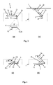
- Fig. 11 shows a development of an actuating means of a supporting device according to the invention.
- the shape memory element 20 is part of a pulley 22, wherein the tension members 21 are attached to the pulley 22.
- the shape memory element 20 is arranged, whose length is reduced when heated, so that the distance between the two rollers of the pulley 22 is also reduced and thus the total length of the actuating means is reduced.
- a pulley 22 as part of the actuating means has the advantage that the adjusting forces to be provided by the shape memory element 20 are kept low, so that inexpensive materials can also be used for the shape memory element.
- a sensor may be provided with which the pipe diameter of a pipe can be detected.
- the control and / or regulating device 30 can then be adapted to determine the temperature to be applied to the shape memory element 20 as a function of the detected pipe diameter.
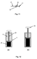
- Fig. 12 shows a further embodiment of a support device according to the invention, wherein in Figure (a) the support device in a neutral position and in Figure (b) the support device is shown with an extended support means 2b.
- the housing 4 is characterized by a cylindrical (eg circular cylindrical) Housing formed in which a designed as a piston rod support means 2b is arranged.
- the piston rod 2 b is led out of the housing 4 with one end.
- the outboard end of the piston rod 2b may be provided to locate or mount work equipment or work support means.
- a contact pressure means 2a is arranged here.
- an adjusting means 20 is arranged, which consists here of a shape memory material.
- the adjusting means 20 is arranged between the bottom of the housing 4 and the inner end of the piston rod 2b, so that the adjusting means 20 can act on the piston rod 2b.
- the actuating means is attached to the bottom of the housing.
- the length of the actuating means 20 increases, so that the inner end of the piston rod 2b is subjected to a thrust force.
- the thrust force causes the piston rod 2b to move relative to the housing 4, so that the piston rod 2b is moved out of the housing, as shown in Figure (b).
- the adjusting means 20 If the adjusting means 20 is no longer subjected to a temperature, the adjusting means 20 returns to its original shape or assumes its original length, as shown in Figure (a). The weight of the piston rod 2b then causes the piston rod 2b is moved back into the housing and the support device returns to the neutral position.
- the piston rod return means 13 can be assigned, which act counter to the actuating force of the actuating means 20.
- the piston rod return means 13 can be assigned, which act counter to the actuating force of the actuating means 20.
- the piston rod return means 13 At the in Fig. 12 embodiment shown are arranged in the interior of the housing 4 configured as compression springs return means.
- a support device has the advantage over a pneumatic or hydraulic cylinder that no pressurized liquids or gases must be supplied to the housing 4. All that is necessary is to supply a power cable in order to supply power to the shape memory material 20 so that it can heat up accordingly.
- the design effort of the support device is significantly reduced compared to pneumatic or hydraulic cylinder.
- the supporting device according to the invention can be made particularly compact. Add to that the in Fig. 12 shown supporting device is particularly flexible - it must be provided only a corresponding power supply, which is much less problematic than providing appropriate pressure line for compressed air or hydraulic oil.
- Another advantage of the supporting device according to the invention is that in case of interruption of the power supply, the support means independently or with the assistance of the return means return to their starting position or neutral position. Because with an interruption of the power supply, the shape memory elements are no longer subjected to a current, so that they cool and return to their original length. An inspection and / or cleaning system can thus be pulled out of the pipe or channel without the support device according to the invention hindering an extraction.
Landscapes
- Engineering & Computer Science (AREA)
- General Engineering & Computer Science (AREA)
- Health & Medical Sciences (AREA)
- Life Sciences & Earth Sciences (AREA)
- Hydrology & Water Resources (AREA)
- Public Health (AREA)
- Water Supply & Treatment (AREA)
- Mechanical Engineering (AREA)
- Chemical & Material Sciences (AREA)
- Combustion & Propulsion (AREA)
- Supports For Pipes And Cables (AREA)
Applications Claiming Priority (1)
| Application Number | Priority Date | Filing Date | Title |
|---|---|---|---|
| DE202014105991.1U DE202014105991U1 (de) | 2014-12-11 | 2014-12-11 | Abstützvorrichtung |
Publications (2)
| Publication Number | Publication Date |
|---|---|
| EP3031991A1 true EP3031991A1 (fr) | 2016-06-15 |
| EP3031991B1 EP3031991B1 (fr) | 2020-06-24 |
Family
ID=54848424
Family Applications (1)
| Application Number | Title | Priority Date | Filing Date |
|---|---|---|---|
| EP15198689.0A Active EP3031991B1 (fr) | 2014-12-11 | 2015-12-09 | Dispositif d'appui |
Country Status (2)
| Country | Link |
|---|---|
| EP (1) | EP3031991B1 (fr) |
| DE (1) | DE202014105991U1 (fr) |
Cited By (2)
| Publication number | Priority date | Publication date | Assignee | Title |
|---|---|---|---|---|
| CN107642654A (zh) * | 2017-09-27 | 2018-01-30 | 南京管科智能科技有限公司 | 一种管道机器人壳体组件 |
| CN114704711A (zh) * | 2022-03-31 | 2022-07-05 | 宁家楠 | 一种城市规划用组合式测绘仪定位调节装置及其使用方法 |
Families Citing this family (1)
| Publication number | Priority date | Publication date | Assignee | Title |
|---|---|---|---|---|
| AT525867B1 (de) * | 2022-04-20 | 2023-09-15 | Matthias Manuel Mueller Ing | Roboter zur grabenlosen Leitungs- und Schachtsanierung |
Citations (9)
| Publication number | Priority date | Publication date | Assignee | Title |
|---|---|---|---|---|
| US2278026A (en) * | 1939-05-03 | 1942-03-31 | William D Osborn | Sewer and pipe cleaner |
| DE9419853U1 (de) * | 1994-12-12 | 1995-08-03 | Sandoz Ag | Höhenverstellbare, in einem Kanal verfahrbare Lafette als Träger eines Kanalbearbeitungsgeräts |
| EP1450095A1 (fr) * | 2003-02-18 | 2004-08-25 | Jens Bauer | Dispositif de travail à l'intérieur de tuyaux |
| DE102007004485A1 (de) * | 2006-08-02 | 2008-05-08 | Schneider, Elmar | Fahrbare gelenkige Kanalinspektionseinheit für die kameraoptische Kanalinspektion in der Rohrachse einschließlich abschnittsweiser Dichtheitsprüfung |
| US7505063B1 (en) * | 2004-02-17 | 2009-03-17 | Ronald A. Basterdo | Self-adjusting and centering camera mount for inspecting pipe |
| DE202010012386U1 (de) * | 2010-09-09 | 2010-11-18 | Ipek International Gmbh | Vorrichtung zur Messung des Innendurchmessers eines Rohres |
| DE202011004376U1 (de) * | 2011-03-24 | 2012-06-26 | Ipek International Gmbh | Hebeeinheit für Rohrinspektionssysteme |
| DE102012004218A1 (de) * | 2012-03-01 | 2013-09-05 | Ibak Helmut Hunger Gmbh & Co Kg | Inspektions- und/oder Sanierungsvorrichtung, insbesondere für Kanalrohre |
| DE102012008202A1 (de) * | 2012-04-19 | 2013-10-24 | Jt Elektronik Gmbh | Fahrwagen für die Inspektion und/oder Sanierung von Kanälen |
-
2014
- 2014-12-11 DE DE202014105991.1U patent/DE202014105991U1/de active Active
-
2015
- 2015-12-09 EP EP15198689.0A patent/EP3031991B1/fr active Active
Patent Citations (9)
| Publication number | Priority date | Publication date | Assignee | Title |
|---|---|---|---|---|
| US2278026A (en) * | 1939-05-03 | 1942-03-31 | William D Osborn | Sewer and pipe cleaner |
| DE9419853U1 (de) * | 1994-12-12 | 1995-08-03 | Sandoz Ag | Höhenverstellbare, in einem Kanal verfahrbare Lafette als Träger eines Kanalbearbeitungsgeräts |
| EP1450095A1 (fr) * | 2003-02-18 | 2004-08-25 | Jens Bauer | Dispositif de travail à l'intérieur de tuyaux |
| US7505063B1 (en) * | 2004-02-17 | 2009-03-17 | Ronald A. Basterdo | Self-adjusting and centering camera mount for inspecting pipe |
| DE102007004485A1 (de) * | 2006-08-02 | 2008-05-08 | Schneider, Elmar | Fahrbare gelenkige Kanalinspektionseinheit für die kameraoptische Kanalinspektion in der Rohrachse einschließlich abschnittsweiser Dichtheitsprüfung |
| DE202010012386U1 (de) * | 2010-09-09 | 2010-11-18 | Ipek International Gmbh | Vorrichtung zur Messung des Innendurchmessers eines Rohres |
| DE202011004376U1 (de) * | 2011-03-24 | 2012-06-26 | Ipek International Gmbh | Hebeeinheit für Rohrinspektionssysteme |
| DE102012004218A1 (de) * | 2012-03-01 | 2013-09-05 | Ibak Helmut Hunger Gmbh & Co Kg | Inspektions- und/oder Sanierungsvorrichtung, insbesondere für Kanalrohre |
| DE102012008202A1 (de) * | 2012-04-19 | 2013-10-24 | Jt Elektronik Gmbh | Fahrwagen für die Inspektion und/oder Sanierung von Kanälen |
Cited By (3)
| Publication number | Priority date | Publication date | Assignee | Title |
|---|---|---|---|---|
| CN107642654A (zh) * | 2017-09-27 | 2018-01-30 | 南京管科智能科技有限公司 | 一种管道机器人壳体组件 |
| CN107642654B (zh) * | 2017-09-27 | 2023-07-28 | 南京管科智能科技有限公司 | 一种管道机器人壳体组件 |
| CN114704711A (zh) * | 2022-03-31 | 2022-07-05 | 宁家楠 | 一种城市规划用组合式测绘仪定位调节装置及其使用方法 |
Also Published As
| Publication number | Publication date |
|---|---|
| DE202014105991U1 (de) | 2016-03-14 |
| EP3031991B1 (fr) | 2020-06-24 |
Similar Documents
| Publication | Publication Date | Title |
|---|---|---|
| DE60303597T2 (de) | Kupplungsvorrichtung in einem hängefördersystem | |
| WO2014053115A1 (fr) | Robot industriel | |
| EP3352950A1 (fr) | Robot industriel | |
| WO2021058473A1 (fr) | Dispositif de pose pour la pose de lignes dans des canaux de câbles | |
| DE102009037515B4 (de) | Vorrichtung und Verfahren zum Führen von Versorgungsleitungen an einem Gelenkroboter | |
| EP3031991A1 (fr) | Dispositif d'appui | |
| EP1961691B1 (fr) | Appareil de transbordement | |
| EP1285878A1 (fr) | Plate-forme élévatrice, en particulier plate-forme élévatrice mobile | |
| DE10329985A1 (de) | Verfahrbares Stativ | |
| AT13742U1 (de) | Energiezuführsystem | |
| DE202011110372U1 (de) | Rotorblatt-Befahranlage | |
| DE102008015392B4 (de) | Vorrichtung zum Anheben von Rohrabschnitten | |
| DE202011100388U1 (de) | Rotorblatt-Befahranlage | |
| DE102012018392A1 (de) | Verfahren zum Betrieb eines Krans und Kran | |
| DE102014118459A1 (de) | Einrichtung zum Vortrieb von Inspektions- und/oder Reinigungssystemen | |
| DE2604046C2 (de) | Einrichtung zum Heben einer Last mit Hilfe eines Schwerlastkrans | |
| DE10130466B4 (de) | Wartungseinrichtung für eine Textilmaschine | |
| EP3031772B1 (fr) | Dispositif de levage, en particulier pour un système d'inspection | |
| EP3293841B1 (fr) | Armature battante de sécurisation des câbles conducteurs | |
| DE102019102285A1 (de) | Klemm- und Hubvorrichtung | |
| EP3556970A1 (fr) | Pompe à béton | |
| EP1378480A1 (fr) | Véhicule de transport pour transporter des éléments de structure | |
| DE202014105990U1 (de) | Einrichtung zum Vortrieb von Inspektions- und/oder Reinigungssystemen | |
| DE202017103858U1 (de) | Anordnung mit zwei Energieführungsketten und verstellbaren Festpunkt | |
| WO2023099062A1 (fr) | Robot de locomotion dans des espaces intérieurs de tuyaux, et procédé de fonctionnement |
Legal Events
| Date | Code | Title | Description |
|---|---|---|---|
| PUAI | Public reference made under article 153(3) epc to a published international application that has entered the european phase |
Free format text: ORIGINAL CODE: 0009012 |
|
| AK | Designated contracting states |
Kind code of ref document: A1 Designated state(s): AL AT BE BG CH CY CZ DE DK EE ES FI FR GB GR HR HU IE IS IT LI LT LU LV MC MK MT NL NO PL PT RO RS SE SI SK SM TR |
|
| AX | Request for extension of the european patent |
Extension state: BA ME |
|
| RAP1 | Party data changed (applicant data changed or rights of an application transferred) |
Owner name: IPEK INTERNATIONAL GMBH |
|
| STAA | Information on the status of an ep patent application or granted ep patent |
Free format text: STATUS: REQUEST FOR EXAMINATION WAS MADE |
|
| 17P | Request for examination filed |
Effective date: 20161214 |
|
| RBV | Designated contracting states (corrected) |
Designated state(s): AL AT BE BG CH CY CZ DE DK EE ES FI FR GB GR HR HU IE IS IT LI LT LU LV MC MK MT NL NO PL PT RO RS SE SI SK SM TR |
|
| STAA | Information on the status of an ep patent application or granted ep patent |
Free format text: STATUS: EXAMINATION IS IN PROGRESS |
|
| 17Q | First examination report despatched |
Effective date: 20190522 |
|
| GRAP | Despatch of communication of intention to grant a patent |
Free format text: ORIGINAL CODE: EPIDOSNIGR1 |
|
| STAA | Information on the status of an ep patent application or granted ep patent |
Free format text: STATUS: GRANT OF PATENT IS INTENDED |
|
| RIC1 | Information provided on ipc code assigned before grant |
Ipc: E03F 9/00 20060101ALI20191216BHEP Ipc: F16L 55/44 20060101ALI20191216BHEP Ipc: F16L 55/18 20060101ALI20191216BHEP Ipc: E03F 7/12 20060101AFI20191216BHEP Ipc: F16L 101/00 20060101ALI20191216BHEP |
|
| INTG | Intention to grant announced |
Effective date: 20200114 |
|
| GRAS | Grant fee paid |
Free format text: ORIGINAL CODE: EPIDOSNIGR3 |
|
| GRAA | (expected) grant |
Free format text: ORIGINAL CODE: 0009210 |
|
| STAA | Information on the status of an ep patent application or granted ep patent |
Free format text: STATUS: THE PATENT HAS BEEN GRANTED |
|
| AK | Designated contracting states |
Kind code of ref document: B1 Designated state(s): AL AT BE BG CH CY CZ DE DK EE ES FI FR GB GR HR HU IE IS IT LI LT LU LV MC MK MT NL NO PL PT RO RS SE SI SK SM TR |
|
| REG | Reference to a national code |
Ref country code: GB Ref legal event code: FG4D Free format text: NOT ENGLISH |
|
| REG | Reference to a national code |
Ref country code: CH Ref legal event code: EP |
|
| REG | Reference to a national code |
Ref country code: AT Ref legal event code: REF Ref document number: 1284031 Country of ref document: AT Kind code of ref document: T Effective date: 20200715 |
|
| REG | Reference to a national code |
Ref country code: DE Ref legal event code: R096 Ref document number: 502015012852 Country of ref document: DE |
|
| REG | Reference to a national code |
Ref country code: IE Ref legal event code: FG4D Free format text: LANGUAGE OF EP DOCUMENT: GERMAN |
|
| PG25 | Lapsed in a contracting state [announced via postgrant information from national office to epo] |
Ref country code: FI Free format text: LAPSE BECAUSE OF FAILURE TO SUBMIT A TRANSLATION OF THE DESCRIPTION OR TO PAY THE FEE WITHIN THE PRESCRIBED TIME-LIMIT Effective date: 20200624 Ref country code: GR Free format text: LAPSE BECAUSE OF FAILURE TO SUBMIT A TRANSLATION OF THE DESCRIPTION OR TO PAY THE FEE WITHIN THE PRESCRIBED TIME-LIMIT Effective date: 20200925 Ref country code: SE Free format text: LAPSE BECAUSE OF FAILURE TO SUBMIT A TRANSLATION OF THE DESCRIPTION OR TO PAY THE FEE WITHIN THE PRESCRIBED TIME-LIMIT Effective date: 20200624 Ref country code: NO Free format text: LAPSE BECAUSE OF FAILURE TO SUBMIT A TRANSLATION OF THE DESCRIPTION OR TO PAY THE FEE WITHIN THE PRESCRIBED TIME-LIMIT Effective date: 20200924 Ref country code: LT Free format text: LAPSE BECAUSE OF FAILURE TO SUBMIT A TRANSLATION OF THE DESCRIPTION OR TO PAY THE FEE WITHIN THE PRESCRIBED TIME-LIMIT Effective date: 20200624 |
|
| REG | Reference to a national code |
Ref country code: LT Ref legal event code: MG4D |
|
| PG25 | Lapsed in a contracting state [announced via postgrant information from national office to epo] |
Ref country code: BG Free format text: LAPSE BECAUSE OF FAILURE TO SUBMIT A TRANSLATION OF THE DESCRIPTION OR TO PAY THE FEE WITHIN THE PRESCRIBED TIME-LIMIT Effective date: 20200924 Ref country code: LV Free format text: LAPSE BECAUSE OF FAILURE TO SUBMIT A TRANSLATION OF THE DESCRIPTION OR TO PAY THE FEE WITHIN THE PRESCRIBED TIME-LIMIT Effective date: 20200624 Ref country code: HR Free format text: LAPSE BECAUSE OF FAILURE TO SUBMIT A TRANSLATION OF THE DESCRIPTION OR TO PAY THE FEE WITHIN THE PRESCRIBED TIME-LIMIT Effective date: 20200624 Ref country code: RS Free format text: LAPSE BECAUSE OF FAILURE TO SUBMIT A TRANSLATION OF THE DESCRIPTION OR TO PAY THE FEE WITHIN THE PRESCRIBED TIME-LIMIT Effective date: 20200624 |
|
| REG | Reference to a national code |
Ref country code: NL Ref legal event code: MP Effective date: 20200624 |
|
| PG25 | Lapsed in a contracting state [announced via postgrant information from national office to epo] |
Ref country code: NL Free format text: LAPSE BECAUSE OF FAILURE TO SUBMIT A TRANSLATION OF THE DESCRIPTION OR TO PAY THE FEE WITHIN THE PRESCRIBED TIME-LIMIT Effective date: 20200624 Ref country code: AL Free format text: LAPSE BECAUSE OF FAILURE TO SUBMIT A TRANSLATION OF THE DESCRIPTION OR TO PAY THE FEE WITHIN THE PRESCRIBED TIME-LIMIT Effective date: 20200624 |
|
| PG25 | Lapsed in a contracting state [announced via postgrant information from national office to epo] |
Ref country code: SM Free format text: LAPSE BECAUSE OF FAILURE TO SUBMIT A TRANSLATION OF THE DESCRIPTION OR TO PAY THE FEE WITHIN THE PRESCRIBED TIME-LIMIT Effective date: 20200624 Ref country code: IT Free format text: LAPSE BECAUSE OF FAILURE TO SUBMIT A TRANSLATION OF THE DESCRIPTION OR TO PAY THE FEE WITHIN THE PRESCRIBED TIME-LIMIT Effective date: 20200624 Ref country code: RO Free format text: LAPSE BECAUSE OF FAILURE TO SUBMIT A TRANSLATION OF THE DESCRIPTION OR TO PAY THE FEE WITHIN THE PRESCRIBED TIME-LIMIT Effective date: 20200624 Ref country code: EE Free format text: LAPSE BECAUSE OF FAILURE TO SUBMIT A TRANSLATION OF THE DESCRIPTION OR TO PAY THE FEE WITHIN THE PRESCRIBED TIME-LIMIT Effective date: 20200624 Ref country code: PT Free format text: LAPSE BECAUSE OF FAILURE TO SUBMIT A TRANSLATION OF THE DESCRIPTION OR TO PAY THE FEE WITHIN THE PRESCRIBED TIME-LIMIT Effective date: 20201026 Ref country code: CZ Free format text: LAPSE BECAUSE OF FAILURE TO SUBMIT A TRANSLATION OF THE DESCRIPTION OR TO PAY THE FEE WITHIN THE PRESCRIBED TIME-LIMIT Effective date: 20200624 Ref country code: ES Free format text: LAPSE BECAUSE OF FAILURE TO SUBMIT A TRANSLATION OF THE DESCRIPTION OR TO PAY THE FEE WITHIN THE PRESCRIBED TIME-LIMIT Effective date: 20200624 |
|
| PG25 | Lapsed in a contracting state [announced via postgrant information from national office to epo] |
Ref country code: IS Free format text: LAPSE BECAUSE OF FAILURE TO SUBMIT A TRANSLATION OF THE DESCRIPTION OR TO PAY THE FEE WITHIN THE PRESCRIBED TIME-LIMIT Effective date: 20201024 Ref country code: SK Free format text: LAPSE BECAUSE OF FAILURE TO SUBMIT A TRANSLATION OF THE DESCRIPTION OR TO PAY THE FEE WITHIN THE PRESCRIBED TIME-LIMIT Effective date: 20200624 Ref country code: PL Free format text: LAPSE BECAUSE OF FAILURE TO SUBMIT A TRANSLATION OF THE DESCRIPTION OR TO PAY THE FEE WITHIN THE PRESCRIBED TIME-LIMIT Effective date: 20200624 |
|
| REG | Reference to a national code |
Ref country code: DE Ref legal event code: R097 Ref document number: 502015012852 Country of ref document: DE |
|
| PG25 | Lapsed in a contracting state [announced via postgrant information from national office to epo] |
Ref country code: DK Free format text: LAPSE BECAUSE OF FAILURE TO SUBMIT A TRANSLATION OF THE DESCRIPTION OR TO PAY THE FEE WITHIN THE PRESCRIBED TIME-LIMIT Effective date: 20200624 |
|
| PLBE | No opposition filed within time limit |
Free format text: ORIGINAL CODE: 0009261 |
|
| STAA | Information on the status of an ep patent application or granted ep patent |
Free format text: STATUS: NO OPPOSITION FILED WITHIN TIME LIMIT |
|
| 26N | No opposition filed |
Effective date: 20210325 |
|
| REG | Reference to a national code |
Ref country code: CH Ref legal event code: PL |
|
| PG25 | Lapsed in a contracting state [announced via postgrant information from national office to epo] |
Ref country code: SI Free format text: LAPSE BECAUSE OF FAILURE TO SUBMIT A TRANSLATION OF THE DESCRIPTION OR TO PAY THE FEE WITHIN THE PRESCRIBED TIME-LIMIT Effective date: 20200624 Ref country code: MC Free format text: LAPSE BECAUSE OF FAILURE TO SUBMIT A TRANSLATION OF THE DESCRIPTION OR TO PAY THE FEE WITHIN THE PRESCRIBED TIME-LIMIT Effective date: 20200624 |
|
| REG | Reference to a national code |
Ref country code: BE Ref legal event code: MM Effective date: 20201231 |
|
| PG25 | Lapsed in a contracting state [announced via postgrant information from national office to epo] |
Ref country code: LU Free format text: LAPSE BECAUSE OF NON-PAYMENT OF DUE FEES Effective date: 20201209 Ref country code: IE Free format text: LAPSE BECAUSE OF NON-PAYMENT OF DUE FEES Effective date: 20201209 |
|
| PG25 | Lapsed in a contracting state [announced via postgrant information from national office to epo] |
Ref country code: LI Free format text: LAPSE BECAUSE OF NON-PAYMENT OF DUE FEES Effective date: 20201231 Ref country code: CH Free format text: LAPSE BECAUSE OF NON-PAYMENT OF DUE FEES Effective date: 20201231 |
|
| REG | Reference to a national code |
Ref country code: AT Ref legal event code: MM01 Ref document number: 1284031 Country of ref document: AT Kind code of ref document: T Effective date: 20201209 |
|
| PG25 | Lapsed in a contracting state [announced via postgrant information from national office to epo] |
Ref country code: AT Free format text: LAPSE BECAUSE OF NON-PAYMENT OF DUE FEES Effective date: 20201209 |
|
| PG25 | Lapsed in a contracting state [announced via postgrant information from national office to epo] |
Ref country code: TR Free format text: LAPSE BECAUSE OF FAILURE TO SUBMIT A TRANSLATION OF THE DESCRIPTION OR TO PAY THE FEE WITHIN THE PRESCRIBED TIME-LIMIT Effective date: 20200624 Ref country code: MT Free format text: LAPSE BECAUSE OF FAILURE TO SUBMIT A TRANSLATION OF THE DESCRIPTION OR TO PAY THE FEE WITHIN THE PRESCRIBED TIME-LIMIT Effective date: 20200624 Ref country code: CY Free format text: LAPSE BECAUSE OF FAILURE TO SUBMIT A TRANSLATION OF THE DESCRIPTION OR TO PAY THE FEE WITHIN THE PRESCRIBED TIME-LIMIT Effective date: 20200624 |
|
| PG25 | Lapsed in a contracting state [announced via postgrant information from national office to epo] |
Ref country code: MK Free format text: LAPSE BECAUSE OF FAILURE TO SUBMIT A TRANSLATION OF THE DESCRIPTION OR TO PAY THE FEE WITHIN THE PRESCRIBED TIME-LIMIT Effective date: 20200624 |
|
| PG25 | Lapsed in a contracting state [announced via postgrant information from national office to epo] |
Ref country code: BE Free format text: LAPSE BECAUSE OF NON-PAYMENT OF DUE FEES Effective date: 20201231 |
|
| PGFP | Annual fee paid to national office [announced via postgrant information from national office to epo] |
Ref country code: GB Payment date: 20231220 Year of fee payment: 9 |
|
| PGFP | Annual fee paid to national office [announced via postgrant information from national office to epo] |
Ref country code: FR Payment date: 20231221 Year of fee payment: 9 Ref country code: DE Payment date: 20231214 Year of fee payment: 9 |