EP3029632A2 - Fahrzeugbilderkennungssystem für anzeigetafelerkennung - Google Patents
Fahrzeugbilderkennungssystem für anzeigetafelerkennung Download PDFInfo
- Publication number
- EP3029632A2 EP3029632A2 EP14831532.8A EP14831532A EP3029632A2 EP 3029632 A2 EP3029632 A2 EP 3029632A2 EP 14831532 A EP14831532 A EP 14831532A EP 3029632 A2 EP3029632 A2 EP 3029632A2
- Authority
- EP
- European Patent Office
- Prior art keywords
- image
- gain
- sign board
- control frame
- exposure time
- Prior art date
- Legal status (The legal status is an assumption and is not a legal conclusion. Google has not performed a legal analysis and makes no representation as to the accuracy of the status listed.)
- Withdrawn
Links
Images


Classifications
-
- G—PHYSICS
- G06—COMPUTING OR CALCULATING; COUNTING
- G06V—IMAGE OR VIDEO RECOGNITION OR UNDERSTANDING
- G06V20/00—Scenes; Scene-specific elements
- G06V20/50—Context or environment of the image
- G06V20/56—Context or environment of the image exterior to a vehicle by using sensors mounted on the vehicle
- G06V20/58—Recognition of moving objects or obstacles, e.g. vehicles or pedestrians; Recognition of traffic objects, e.g. traffic signs, traffic lights or roads
- G06V20/582—Recognition of moving objects or obstacles, e.g. vehicles or pedestrians; Recognition of traffic objects, e.g. traffic signs, traffic lights or roads of traffic signs
-
- H—ELECTRICITY
- H04—ELECTRIC COMMUNICATION TECHNIQUE
- H04N—PICTORIAL COMMUNICATION, e.g. TELEVISION
- H04N23/00—Cameras or camera modules comprising electronic image sensors; Control thereof
- H04N23/50—Constructional details
- H04N23/54—Mounting of pick-up tubes, electronic image sensors, deviation or focusing coils
-
- H—ELECTRICITY
- H04—ELECTRIC COMMUNICATION TECHNIQUE
- H04N—PICTORIAL COMMUNICATION, e.g. TELEVISION
- H04N23/00—Cameras or camera modules comprising electronic image sensors; Control thereof
- H04N23/70—Circuitry for compensating brightness variation in the scene
- H04N23/72—Combination of two or more compensation controls
-
- H—ELECTRICITY
- H04—ELECTRIC COMMUNICATION TECHNIQUE
- H04N—PICTORIAL COMMUNICATION, e.g. TELEVISION
- H04N23/00—Cameras or camera modules comprising electronic image sensors; Control thereof
- H04N23/70—Circuitry for compensating brightness variation in the scene
- H04N23/73—Circuitry for compensating brightness variation in the scene by influencing the exposure time
-
- H—ELECTRICITY
- H04—ELECTRIC COMMUNICATION TECHNIQUE
- H04N—PICTORIAL COMMUNICATION, e.g. TELEVISION
- H04N23/00—Cameras or camera modules comprising electronic image sensors; Control thereof
- H04N23/70—Circuitry for compensating brightness variation in the scene
- H04N23/74—Circuitry for compensating brightness variation in the scene by influencing the scene brightness using illuminating means
-
- H—ELECTRICITY
- H04—ELECTRIC COMMUNICATION TECHNIQUE
- H04N—PICTORIAL COMMUNICATION, e.g. TELEVISION
- H04N23/00—Cameras or camera modules comprising electronic image sensors; Control thereof
- H04N23/70—Circuitry for compensating brightness variation in the scene
- H04N23/743—Bracketing, i.e. taking a series of images with varying exposure conditions
-
- H—ELECTRICITY
- H04—ELECTRIC COMMUNICATION TECHNIQUE
- H04N—PICTORIAL COMMUNICATION, e.g. TELEVISION
- H04N23/00—Cameras or camera modules comprising electronic image sensors; Control thereof
- H04N23/70—Circuitry for compensating brightness variation in the scene
- H04N23/76—Circuitry for compensating brightness variation in the scene by influencing the image signals
Definitions
- the present invention relates to an ADAS image recognition technology for a vehicle, and particularly, to an ADAS image recognition system mounted in a vehicle to recognize a traffic sign board installed on a road during traveling.
- ADAS Advanced Driver Assistance System
- An ADAS image recognition apparatus recognizes information (a lane, another vehicle, a light source, a pedestrian, and a traffic sign board) on a road, on which a vehicle is traveling, by using an image recognition technology.
- a traffic sign board Since a traffic sign board has been typically manufactured by drawing a standardized mark having a specific shape on a circular or triangular plate, there have been made efforts to develop a traffic sign board recognition apparatus for recognizing the shape and mark of the traffic sign board by using an image processing technique, to inform a driver of a current traveling environment on a road, and to improve traveling safety and convenience.
- an LED is mainly applied to a traffic sign board in Europe, and is also partially introduced in South Korea. Since a light emitting type sign board is less affected by peripheral illumination and the content of the sign board can be variably displayed or luminance can be changed, it is applied for improvement of visibility at night, traffic, and a change in a limit speed due to weather.
- the ADAS image recognition apparatus processes a digital image input through a camera by using a numerical analysis technique, its performance may be largely depend on the characteristics of an input image.
- a reflective traffic sign board since sunlight in the daytime, a street light at night, and headlights of its own vehicle and other vehicles are mainly reflected by the traffic sign board, are incident into a camera of the ADAS image recognition apparatus, and are converted into a digital image, the reflective traffic sign board is largely affected by the brightness or direction of a peripheral light source. Meanwhile, in the case of the light emitting type sign board, since light emitted from its own light source, regardless of other light sources, is incident into a camera of the image recognition apparatus, it is not affected by a peripheral light source. Due to such a difference of characteristics therebetween, it is difficult to capture two types of traffic sign boards so as to be recognized in the same camera.
- traffic sign board detection and recognition technologies are developed in order to achieve an intelligent vehicle system capable of performing manless driving, but a technology capable of reliably recognizing both the reflective traffic sign board and the light emitting type sign board is not still proposed in these technologies.
- the present invention has an object for providing an image recognition system for a vehicle for traffic sign board recognition, capable of improving the recognition performance of a traffic sign board.
- the present invention has an object for providing an image recognition system for a vehicle for traffic sign board recognition, capable of improving the recognition performance of a reflective traffic sign board and a light emitting type traffic sign board by adjusting an exposure of a camera.
- the present invention has an object for providing an image recognition system for a vehicle for traffic sign board recognition, capable of improving the recognition performance of a reflective traffic sign board and a light emitting type traffic sign board by adjusting an amplification ratio of an image signal.
- the present invention has an object for providing an image recognition system for a vehicle for traffic sign board recognition, capable of improving the recognition performance of a reflective traffic sign board and a light emitting type traffic sign board by simultaneously adjusting an exposure of a camera and an amplification ratio of an image signal.
- an exposure time of a camera lens or gain of an image output from an image sensor can be adjusted to generate at least one image group including a plurality of frames in which the exposure time and the gain are different from each other, sign board regions of the plurality of frames can be compared with each other, and an image nearest to a predetermined set value can be selected.
- At least one of the plurality of frames is an auto-exposure control frame in which brightness of entire of a screen or a region of interest in the screen is constantly maintained.
- the auto-exposure control frame can be acquired by fixing the exposure time of the camera lens and adjusting the gain of the image.
- the auto-exposure control frame can be acquired by fixing the gain of the image and adjusting the exposure time of the camera lens.
- the auto-exposure control frame can be acquired by adjusting the exposure time of the camera lens and the gain of the image.
- At least one of the plurality of frames is an over-exposure control frame in which brightness of the image is maintained to be bright as compared with the auto-exposure control frame.
- the over-exposure control frame can be acquired by maintaining the exposure time of the camera lens to be equal to that of the auto-exposure control frame and increasing the gain of the image.
- the over-exposure control frame can be acquired by maintaining the gain of the image to be equal to that of the auto-exposure control frame and extending the exposure time of the camera lens.
- the over-exposure control frame can be acquired by increasing the gain of the image and the exposure time of the camera lens as compared with those of the auto-exposure control frame.
- the over-exposure control frame can be acquired by increasing multiplication of the gain of the image and the exposure time of the camera lens as compared with multiplication of those of the auto-exposure control frame.
- At least one of the plurality of frames is a low exposure control frame in which brightness of the image is maintained to be dark as compared with the auto-exposure control frame.
- the low exposure control frame can be acquired by maintaining the exposure time of the camera lens to be equal to that of the auto-exposure control frame and decreasing the gain of the image.
- the low exposure control frame can be acquired by maintaining the gain of the image to be equal to that of the auto-exposure control frame and shortening the exposure time of the camera lens.
- the low exposure control frame can be acquired by decreasing the gain of the image and the exposure time of the camera lens as compared with those of the auto-exposure control frame.
- the low exposure control frame can be acquired by decreasing multiplication of the gain of the image and the exposure time of the camera lens as compared with multiplication of those of the auto-exposure control frame.
- At least one of the plurality of frames is a fixed exposure control frame in which the exposure time of the camera lens and the gain of the image are constantly maintained.
- At least one of the plurality of frames is a frame in which the exposure time of the camera lens is constantly maintained and the gain of the image is controlled such that an average brightness of the region of interest is equal to a preset reference value.
- the brightness of the auto-exposure control frame can be compared with a brightness of an input image, it can be determined as a daytime condition when the brightness of the input image is equal to or more than the brightness of the auto-exposure control frame, and the exposure time or the gain can be changed and applied with respect to at least one of the plurality of frames forming the image group.
- a head lamp signal of a vehicle it can be determined as a daytime condition when the head lamp signal is OFF, and parameter setting of at least one of the plurality of frames forming group 1 can be changed and applied.
- a traffic sign board recognition method includes the steps of: acquiring an image group including a plurality of frames; searching for bands having predetermined colors and predetermined shapes from an auto-exposure control frame of the plurality of frames; comparing brightnesses of the bands existing in the plurality of frames of the image group with each other when there exist the bands having predetermined colors and predetermined shapes; selecting a frame including a band nearest a preset reference value among the bands existing in the plurality of frames; and performing image processing on the selected frame and recognizing a sign board.
- An image recognition apparatus for a vehicle includes: a central control unit that adjusts an exposure time of a camera lens or gain of an image output from an image sensor and generates at least one image group including frames in which the exposure time and the gain are different from each other; a first storage unit that stores a plurality of parameter sets, each parameter set including the exposure time and the gain; and a second storage unit that stores at least two image frames different from each other.
- the present invention it is possible to improve the recognition performance of a reflective traffic sign board and a light emitting type traffic sign board by adjusting an exposure of a camera, to improve the recognition performance of a reflective traffic sign board and a light emitting type traffic sign board by adjusting an amplification ratio of an image signal, and to improve the recognition performance of a reflective traffic sign board and a light emitting type traffic sign board by simultaneously adjusting an exposure of a camera and an amplification ratio of an image signal.
- a light emitting type traffic sign board is processed to be excessively bright
- the light emitting type traffic sign board is processed to be excessively dark
- the backlight indicates that light of the light source is directly incident into a camera, and the follow light indicates that light of the light source is not directly incident into the camera.
- Fig. 1 illustrates the case in which follow light is incident into a camera of an image recognition apparatus, wherein since only light scattered from a road of light of a light source is incident into the camera, but most light reflected from a plate sign board is incident into the camera, the sign board is shown to be relatively brighter than the surrounding area.
- Fig. 2 illustrates the case in which backlight is incident into a camera of an image recognition apparatus, wherein since most light reflected from a road of a light source is incident into the camera, but some of scattered light of the light source is reflected from a plate sign board and is incident into the camera, the sign board is shown to be relatively darker than the surrounding area.
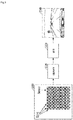
- Fig. 3 is a conceptual diagram for explaining image generation in a digital camera, wherein optical sensors in units of pixels are arranged in an array form in an image sensor of the camera and electric charge is generated by a photoelectric effect when light is incident (S310), the electric charge is exposed by light for a predetermined time and is accumulated (S320), and the accumulated electric charge is amplified (S330), so that an image having brightness corresponding to each pixel is generated (S340).
- the brightness of the image is decided by light exposure time for charge accumulation and an amplification ratio of a signal.
- the brightness of the screen it is possible to control the brightness of the screen to be constantly maintained by adjusting the exposure or the gain, or simultaneously adjusting the exposure and the gain in correspondence to the luminance of the region of interest.
- a reflective sign board has reflective characteristics different from those of a road according to the direction of the sun, when the reflective sign board is captured by the camera of the image recognition apparatus, it is highly probable that it is difficult to recognize the reflective sign board from an image captured by the camera.
- Fig. 5 is a block diagram of an image recognition apparatus according to an embodiment of the present invention, and includes a camera unit 510 and an image processing unit 520.
- the camera unit 510 includes a lens 511, an image sensor 513, a lens fixing section 515 that fixes the lens and the image sensor, an operation control memory 517, and a first power supply (not illustrated) that supplies power to the image sensor.
- the operation control memory 517 stores setting parameters (an exposure time and gain) for an operation of a camera according to each image frame.
- the image processing unit 520 includes a CPU 521 that stores setting parameters according to each corresponding frame in the operation control memory 517 at a predetermined time interval and processes an image output from the image sensor 513, a volatile memory 523 that stores original image data and image data being processed, a nonvolatile memory 525, an interface 527 that transmits/receives signals to/from other electronic devices of a vehicle, and a power supply (not illustrated) that supplies power to each element.
- Fig. 6 is a conceptual diagram for explaining the generation of a plurality of images according to an embodiment of the present invention, wherein it is possible to repeatedly generate a plurality of image frames in which factors for adjusting the target brightness of a screen by the camera unit 510 of the image recognition apparatus have been differently set.
- an image recognition system can form four frames (frame 0 to frame 3) as one group and can periodically generate the four frames. That is, the image recognition system captures images having different characteristics in the same period of time, analyzes each image to select an image suitable for sign board recognition, and analyzes a sign board region of the corresponding image, thereby recognizing sign board information.
- the image recognition system designates a road region or an entire screen as a region of interest in the frame 0 and applies the auto-exposure control. Then, an exposure time of the camera lens and gain of an image in the frame 0 can be stored in the operation control memory 517, and can be provided as a reference value for adjusting the brightness of another frame.
- the frame 0 is available for recognizing a sign board when light is not excessive backlight or excessive follow light.
- the image recognition system can constantly maintain the brightness of an entire screen or a region of interest by fixing the exposure time of the camera lens and adjusting the gain of the image.
- the image recognition system can constantly maintain the brightness of the entire screen or the region of interest by fixing the gain of the image and adjusting the exposure time of the camera lens. According to further another embodiment of the present invention, the image recognition system can constantly maintain the brightness of the entire screen or the region of interest by adjusting the exposure time of the camera lens and the gain of the image.
- the excessive backlight indicates the case in which the sun is positioned in front of the camera and at the back of the sign board
- the excessive follow light indicates the case in which the sun is positioned at the back of the camera and in front of the sign board.
- the exposure time of the camera lens corresponding to the frame 1 and the gain of the image are stored in the operation control memory 517, and the CPU 521 in the image processing unit 520 reads a parameter (an exposure time and/or gain) setting value, to which over-exposure control for adjusting the brightness of a screen in the frame 1 to be brighter than that of the frame 0 (auto-exposure control) has been applied, from the operation control memory 517, and processes the image.
- a parameter an exposure time and/or gain setting value
- the exposure time of the camera lens set to be longer than that of the frame 0 by a predetermined time and the gain of an image set to be equal to that of the frame 0 can be stored.
- the gain of an image set to be higher than that of the frame 0 by a predetermined ratio and the exposure time of the camera lens set to be equal to that of the frame 0 can be stored.
- the exposure time of the camera lens and the gain of an image respectively set to be higher than those of the frame 0 by a predetermined value can be stored.
- multiplication of the exposure time of the camera lens and the gain of an image set to be higher than that of the frame 0 can be stored.
- the image processing unit 520 increases the exposure time of the camera lens and the gain of the image such that the target brightness of the screen is constantly maintained, according to the auto-exposure control function. Meanwhile, since the luminance of the sign board is increased by the follow light, the brightness of the sign board is increased and saturated, so that the recognition of the sign board is not possible.
- the CPU 521 in the image processing unit 520 reads a parameter (an exposure time and/or gain) setting value, to which low exposure control for adjusting the brightness of a screen in the frame 2 to be darker than that of the frame 0 (auto-exposure control) has been applied, from the operation control memory 517, and processes the image.
- a parameter an exposure time and/or gain setting value
- the exposure time of the camera lens set to be shorter than that of the frame 0 by a predetermined time and the gain of an image set to be equal to that of the frame 0 can be stored.
- the gain of an image set to be lower than that of the frame 0 by a predetermined value and the exposure time of the camera lens set to be equal to that of the frame 0 can be stored.
- the exposure time of the camera lens and the gain of an image respectively set to be lower than those of the frame 0 by a predetermined value can be stored.
- multiplication of the exposure time of the camera lens and the gain of an image set to be lower than that of the frame 0 can be stored.
- the CPU 521 in the image processing unit 520 reads a parameter (an exposure time and/or gain) setting value, to which constant exposure control for constantly maintaining the exposure time of the camera lens and the gain of an image regardless of the brightness of the entire screen or the region of interest has been applied, from the operation control memory 517, and processes the image.
- a parameter an exposure time and/or gain setting value
- the exposure time of the camera lens and the gain of an image fixedly set as predetermined values in correspondence to the frame 3 and can be stored.
- the recognition of the sign board is easy in the frame 3 as compared with the frame 0 based on the auto-exposure control in which the exposure time of the camera lens and the gain of an image are differently controlled according to the surrounding brightness.
- At least one of a plurality of frames forming group 1 may be a frame in which gain has been controlled such that the average brightness of a road region is equal to predetermined reference brightness while constantly maintaining the exposure time of the camera lens.
- the brightness of the frame 0 is compared with the brightness of an input image, it is determined as a daytime condition when the brightness of the input image is equal to or more than the brightness of the frame 0, and it is determined as a night condition when the brightness of the input image is equal to or less than the brightness of the frame 0, so that it is possible to change and apply parameter setting of at least one of a plurality of frames forming group 1.
- a head lamp signal of a vehicle it is determined as a daytime condition when the head lamp signal is OFF and it is determined as a night condition when the head lamp signal is ON, so that it is possible to change and apply parameter setting of at least one of a plurality of frames forming group 1.
- the image processing control unit of the camera can form at least two of the frame 0 to the frame 3 as one group and periodically generate the frames.
- the image processing control unit of the camera can periodically generate the frame 0, the frame 1, and the frame 3.
- the image processing control unit of the camera can periodically generate the frame 0, the frame 2, and the frame 3.
- the image processing control unit of the camera can periodically generate the frame 0 and the frame 3.
- Fig. 7 is a flowchart for explaining frame selection according to an embodiment of the present invention.
- red circular bands of the frame 0 (the auto-exposure control frame) are searched (S720).
- the red circular band exists S730
- the brightnesses of the circular bands existing in the frames of the group are compared with each other (S740)
- a frame including a circular band nearest to a preset reference value is selected (S750)
- the selected frame is subjected to image processing to recognize a sign board (S760)
- the procedure is ended (S770).
- the red circular band has been described as an example, but a traffic sign board is not limited to such color and shape.
- the traffic sign board may be rectangular or triangular, and may be blue or green. Since a technology for detecting a traffic sign board having such color and shape is obvious for those skilled in the art, a detailed description thereof will be omitted.
Landscapes
- Engineering & Computer Science (AREA)
- Multimedia (AREA)
- Signal Processing (AREA)
- Physics & Mathematics (AREA)
- General Physics & Mathematics (AREA)
- Theoretical Computer Science (AREA)
- Studio Devices (AREA)
- Traffic Control Systems (AREA)
- Image Processing (AREA)
- Exposure Control For Cameras (AREA)
- Closed-Circuit Television Systems (AREA)
Applications Claiming Priority (2)
| Application Number | Priority Date | Filing Date | Title |
|---|---|---|---|
| KR1020130090630A KR101353052B1 (ko) | 2013-07-31 | 2013-07-31 | 교통표지판 인식을 위한 차량용 영상인식시스템 |
| PCT/KR2014/003902 WO2015016461A2 (ko) | 2013-07-31 | 2014-05-01 | 교통표지판 인식을 위한 차량용 영상인식시스템 |
Publications (2)
| Publication Number | Publication Date |
|---|---|
| EP3029632A2 true EP3029632A2 (de) | 2016-06-08 |
| EP3029632A4 EP3029632A4 (de) | 2017-03-29 |
Family
ID=50145938
Family Applications (1)
| Application Number | Title | Priority Date | Filing Date |
|---|---|---|---|
| EP14831532.8A Withdrawn EP3029632A4 (de) | 2013-07-31 | 2014-05-01 | Fahrzeugbilderkennungssystem für anzeigetafelerkennung |
Country Status (5)
| Country | Link |
|---|---|
| US (1) | US9639764B2 (de) |
| EP (1) | EP3029632A4 (de) |
| KR (1) | KR101353052B1 (de) |
| CN (1) | CN104937637B (de) |
| WO (1) | WO2015016461A2 (de) |
Families Citing this family (20)
| Publication number | Priority date | Publication date | Assignee | Title |
|---|---|---|---|---|
| KR102174000B1 (ko) * | 2014-05-30 | 2020-11-04 | 주식회사 만도 | 차량 표지판 인식 시스템 및 그를 위한 방법 |
| DE102015207902A1 (de) | 2015-04-29 | 2016-11-03 | Mando Corporation | Verfahren und Vorrichtung zur Bestätigung des relevanten inneren weißen Kreises bei der Erkennung des Umfelds eines kreisförmigen Verkehrszeichens |
| KR102465335B1 (ko) * | 2015-11-19 | 2022-11-11 | 주식회사 에이치엘클레무브 | 헤드램프 인식 장치 및 방법 |
| US10325339B2 (en) * | 2016-04-26 | 2019-06-18 | Qualcomm Incorporated | Method and device for capturing image of traffic sign |
| US10169649B2 (en) | 2016-07-28 | 2019-01-01 | International Business Machines Corporation | Smart image filtering method with domain rules application |
| KR102883417B1 (ko) * | 2017-02-24 | 2025-11-06 | 삼성전자주식회사 | 자율 주행을 위한 영상 처리 방법 및 장치 |
| US10453208B2 (en) | 2017-05-19 | 2019-10-22 | Waymo Llc | Camera systems using filters and exposure times to detect flickering illuminated objects |
| JP6759460B2 (ja) * | 2017-06-07 | 2020-09-23 | 日立オートモティブシステムズ株式会社 | 画像処理装置 |
| KR102519662B1 (ko) | 2017-07-31 | 2023-04-07 | 삼성전자주식회사 | 영상 획득 방법 및 영상 획득 장치 |
| DE102017119394A1 (de) * | 2017-08-28 | 2019-02-28 | HELLA GmbH & Co. KGaA | Verfahren zur Ansteuerung mindestens eines Lichtmoduls einer Leuchteinheit eines Fahrzeugs, Leuchteinheit, Computerprogrammprodukt und computerlesbares Medium |
| JP6866934B2 (ja) * | 2017-12-05 | 2021-04-28 | 日産自動車株式会社 | 車両の制御方法及び制御装置 |
| JP6868932B2 (ja) * | 2018-01-12 | 2021-05-12 | 日立Astemo株式会社 | 物体認識装置 |
| KR101900073B1 (ko) | 2018-01-15 | 2018-09-19 | 김홍진 | 정보 생성 기능을 갖는 반사체 |
| JP7289723B2 (ja) * | 2019-05-23 | 2023-06-12 | 日立Astemo株式会社 | 物体認識装置 |
| CN110519526B (zh) * | 2019-09-09 | 2021-02-26 | Oppo广东移动通信有限公司 | 曝光时长控制方法、装置、存储介质及电子设备 |
| US11702140B2 (en) | 2019-11-19 | 2023-07-18 | Robert Bosch Gmbh | Vehicle front optical object detection via photoelectric effect of metallic striping |
| KR20210079638A (ko) | 2019-12-20 | 2021-06-30 | 한국건설기술연구원 | 영상 자료를 활용한 교통표지의 인식장치 및 인식방법 |
| CN111212223B (zh) * | 2020-01-10 | 2021-01-22 | 奥比中光科技集团股份有限公司 | 一种设定成像参数的方法、系统及计算机可读存储介质 |
| KR102538104B1 (ko) * | 2022-06-17 | 2023-05-31 | 한국건설기술연구원 | 라이다 검지형 도로 시설물 |
| WO2026041933A1 (en) * | 2024-08-23 | 2026-02-26 | Samsung Electronics Co., Ltd. | Method and system for operating a flashlight of a camera unit |
Family Cites Families (25)
| Publication number | Priority date | Publication date | Assignee | Title |
|---|---|---|---|---|
| US6295415B1 (en) * | 1995-06-01 | 2001-09-25 | Canon Kabushiki Kaisha | Camera |
| ATE386951T1 (de) | 2002-08-05 | 2008-03-15 | Elbit Systems Ltd | Nachtsichtabbildungssystem und -verfahren zur montage in einem fahrzeug |
| US20050128063A1 (en) * | 2003-11-28 | 2005-06-16 | Denso Corporation | Vehicle driving assisting apparatus |
| JP2008028957A (ja) * | 2006-07-25 | 2008-02-07 | Denso Corp | 車両用画像処理装置 |
| US8064643B2 (en) * | 2006-12-06 | 2011-11-22 | Mobileye Technologies Limited | Detecting and recognizing traffic signs |
| JP2008187317A (ja) * | 2007-01-29 | 2008-08-14 | Fujifilm Corp | 撮影装置およびその制御方法並びにプログラム |
| JP4987573B2 (ja) * | 2007-06-01 | 2012-07-25 | 富士重工業株式会社 | 車外監視装置 |
| CN101359148B (zh) | 2007-08-03 | 2011-04-06 | 深圳艾科创新微电子有限公司 | 一种用于自动曝光调节的方法及控制系统 |
| ATE499671T1 (de) * | 2007-08-17 | 2011-03-15 | Magneti Marelli Spa | Verfahren und system zur erkennung von verkehrszeichen mit zusatztafeln |
| JP4433046B2 (ja) * | 2007-12-26 | 2010-03-17 | 株式会社デンソー | 露出制御装置及び露出制御プログラム |
| US8441535B2 (en) * | 2008-03-05 | 2013-05-14 | Omnivision Technologies, Inc. | System and method for independent image sensor parameter control in regions of interest |
| ES2585214T3 (es) * | 2008-09-22 | 2016-10-04 | Freedom Scientific Inc. | Sistemas y métodos para formar imagen de objetos |
| EP3975138B1 (de) * | 2008-10-06 | 2024-12-11 | Mobileye Vision Technologies Ltd. | Bündelung von fahrerassistenzsystemen |
| JP4666049B2 (ja) * | 2008-10-17 | 2011-04-06 | 株式会社デンソー | 光源識別装置、光源識別プログラム、車両検出装置、およびライト制御装置 |
| JP5294995B2 (ja) * | 2009-06-03 | 2013-09-18 | パナソニック株式会社 | 距離計測装置及び距離計測方法 |
| CN102598650A (zh) * | 2009-11-04 | 2012-07-18 | 丰田自动车株式会社 | 摄像装置、调整装置和摄像装置的光轴调整系统 |
| US8558913B2 (en) * | 2010-02-08 | 2013-10-15 | Apple Inc. | Capture condition selection from brightness and motion |
| JP5246254B2 (ja) * | 2010-12-24 | 2013-07-24 | 株式会社デンソー | 車載カメラの露出制御値の決定方法 |
| JP2012221103A (ja) * | 2011-04-06 | 2012-11-12 | Denso Corp | 車両用画像処理装置 |
| KR101259836B1 (ko) * | 2011-08-08 | 2013-05-02 | 주식회사 피엘케이 테크놀로지 | 우적 감응형 와이퍼 장치 |
| KR20130030667A (ko) * | 2011-09-19 | 2013-03-27 | 최재순 | 증강 현실을 이용한 자동차 운행 보조 시스템 |
| JP5832855B2 (ja) * | 2011-11-01 | 2015-12-16 | クラリオン株式会社 | 画像処理装置、撮像装置および画像処理プログラム |
| KR101298937B1 (ko) * | 2011-11-11 | 2013-08-23 | 서강대학교산학협력단 | 표지판 인식장치, 표지판 인식방법, 및 이미지 인식방법 |
| JP5937832B2 (ja) * | 2012-01-30 | 2016-06-22 | クラリオン株式会社 | 車載カメラ用露出制御装置 |
| CN102819728A (zh) * | 2012-07-17 | 2012-12-12 | 中国航天科工集团第三研究院第八三五七研究所 | 一种基于分类模板匹配的交通标志检测方法 |
-
2013
- 2013-07-31 KR KR1020130090630A patent/KR101353052B1/ko active Active
-
2014
- 2014-05-01 US US14/765,004 patent/US9639764B2/en active Active
- 2014-05-01 CN CN201480005780.7A patent/CN104937637B/zh active Active
- 2014-05-01 WO PCT/KR2014/003902 patent/WO2015016461A2/ko not_active Ceased
- 2014-05-01 EP EP14831532.8A patent/EP3029632A4/de not_active Withdrawn
Also Published As
| Publication number | Publication date |
|---|---|
| CN104937637B (zh) | 2017-09-15 |
| US20150371097A1 (en) | 2015-12-24 |
| CN104937637A (zh) | 2015-09-23 |
| US9639764B2 (en) | 2017-05-02 |
| KR101353052B1 (ko) | 2014-01-20 |
| EP3029632A4 (de) | 2017-03-29 |
| WO2015016461A2 (ko) | 2015-02-05 |
| WO2015016461A3 (ko) | 2015-04-09 |
Similar Documents
| Publication | Publication Date | Title |
|---|---|---|
| US9639764B2 (en) | Image recognition system for vehicle for traffic sign board recognition | |
| US10377322B2 (en) | In-vehicle camera and vehicle control system | |
| US9626570B2 (en) | Vehicle control system and image sensor | |
| US9690997B2 (en) | Recognition object detecting apparatus | |
| JP5071198B2 (ja) | 信号機認識装置,信号機認識方法および信号機認識プログラム | |
| JP4853437B2 (ja) | 車両周辺監視システム | |
| CN101142814A (zh) | 图像处理装置及方法、程序、以及记录介质 | |
| US20160048734A1 (en) | Light source recognition system of vehicle | |
| JP2016196233A (ja) | 車両用道路標識認識装置 | |
| CN101142812A (zh) | 图像处理装置和方法、程序、及记录介质 | |
| CN113490316A (zh) | 一种补光系统及补光灯 | |
| EP3220637B1 (de) | Fahrzeugmontiertes kamerasystem | |
| JP6267493B2 (ja) | 矢印信号灯検出装置 | |
| KR102155374B1 (ko) | 자동차용 야간 화상들을 형성하는 시스템 및 방법 | |
| US11882367B2 (en) | Image processing method for producing a high dynamic range image of a scene | |
| US10829042B2 (en) | Imaging apparatus with image sensor for detecting light in an atmospheric peak and vehicle having same | |
| WO2018225516A1 (ja) | 画像処理装置 | |
| US9832398B2 (en) | Camera system, especially for a vehicle, and method for ascertaining image information of a signal source pulsed as a function of time | |
| EP3568972A1 (de) | Verfahren zum betrieb einer kamera je nach einem aktuellen zustand eines umgebungsbereichs der kamera, kamera und kraftfahrzeug | |
| JP4782491B2 (ja) | 撮像装置 | |
| JP2014021716A (ja) | 標識案内表示装置および標識案内表示方法 | |
| JP7725947B2 (ja) | オブジェクト認識制御装置およびオブジェクト認識制御方法 | |
| EP2560391A1 (de) | Abbildungssystem in einem Kraftfahrzeug und entsprechendes Abbildungsverfahren | |
| JP2018182540A (ja) | 表示制御装置、表示制御方法及びカメラモニタリングシステム | |
| JP2006211456A (ja) | 車両用画像提示装置及び方法 |
Legal Events
| Date | Code | Title | Description |
|---|---|---|---|
| PUAI | Public reference made under article 153(3) epc to a published international application that has entered the european phase |
Free format text: ORIGINAL CODE: 0009012 |
|
| 17P | Request for examination filed |
Effective date: 20150810 |
|
| AK | Designated contracting states |
Kind code of ref document: A2 Designated state(s): AL AT BE BG CH CY CZ DE DK EE ES FI FR GB GR HR HU IE IS IT LI LT LU LV MC MK MT NL NO PL PT RO RS SE SI SK SM TR |
|
| AX | Request for extension of the european patent |
Extension state: BA ME |
|
| DAX | Request for extension of the european patent (deleted) | ||
| A4 | Supplementary search report drawn up and despatched |
Effective date: 20170227 |
|
| RIC1 | Information provided on ipc code assigned before grant |
Ipc: G06T 7/00 20170101AFI20170221BHEP Ipc: H04N 5/232 20060101ALI20170221BHEP |
|
| 17Q | First examination report despatched |
Effective date: 20200417 |
|
| STAA | Information on the status of an ep patent application or granted ep patent |
Free format text: STATUS: THE APPLICATION IS DEEMED TO BE WITHDRAWN |
|
| 18D | Application deemed to be withdrawn |
Effective date: 20200828 |