EP3028358B1 - Steuersystem und verfahren für ein mikrostromnetz - Google Patents
Steuersystem und verfahren für ein mikrostromnetz Download PDFInfo
- Publication number
- EP3028358B1 EP3028358B1 EP14750273.6A EP14750273A EP3028358B1 EP 3028358 B1 EP3028358 B1 EP 3028358B1 EP 14750273 A EP14750273 A EP 14750273A EP 3028358 B1 EP3028358 B1 EP 3028358B1
- Authority
- EP
- European Patent Office
- Prior art keywords
- microgrid
- distributed
- time window
- energy storage
- control objective
- Prior art date
- Legal status (The legal status is an assumption and is not a legal conclusion. Google has not performed a legal analysis and makes no representation as to the accuracy of the status listed.)
- Active
Links
Images


Classifications
-
- G—PHYSICS
- G05—CONTROLLING; REGULATING
- G05B—CONTROL OR REGULATING SYSTEMS IN GENERAL; FUNCTIONAL ELEMENTS OF SUCH SYSTEMS; MONITORING OR TESTING ARRANGEMENTS FOR SUCH SYSTEMS OR ELEMENTS
- G05B13/00—Adaptive control systems, i.e. systems automatically adjusting themselves to have a performance which is optimum according to some preassigned criterion
- G05B13/02—Adaptive control systems, i.e. systems automatically adjusting themselves to have a performance which is optimum according to some preassigned criterion electric
-
- H—ELECTRICITY
- H02—GENERATION; CONVERSION OR DISTRIBUTION OF ELECTRIC POWER
- H02J—ELECTRIC POWER NETWORKS; CIRCUIT ARRANGEMENTS OR SYSTEMS FOR SUPPLYING OR DISTRIBUTING ELECTRIC POWER; SYSTEMS FOR STORING ELECTRIC ENERGY
- H02J3/00—Circuit arrangements for AC mains or AC distribution networks
-
- Y—GENERAL TAGGING OF NEW TECHNOLOGICAL DEVELOPMENTS; GENERAL TAGGING OF CROSS-SECTIONAL TECHNOLOGIES SPANNING OVER SEVERAL SECTIONS OF THE IPC; TECHNICAL SUBJECTS COVERED BY FORMER USPC CROSS-REFERENCE ART COLLECTIONS [XRACs] AND DIGESTS
- Y02—TECHNOLOGIES OR APPLICATIONS FOR MITIGATION OR ADAPTATION AGAINST CLIMATE CHANGE
- Y02P—CLIMATE CHANGE MITIGATION TECHNOLOGIES IN THE PRODUCTION OR PROCESSING OF GOODS
- Y02P80/00—Climate change mitigation technologies for sector-wide applications
- Y02P80/10—Efficient use of energy, e.g. using compressed air or pressurized fluid as energy carrier
- Y02P80/14—District level solutions, i.e. local energy networks
Definitions
- the instant application relates to microgrids, and more particularly to controlling operation of microgrids.
- a microgrid is a semiautonomous grouping of distributed energy resources (distributed generation and energy storage) and loads within a local area.
- the loads can be one utility "customer," a grouping of several sites, or dispersed sites that operate in a coordinated fashion.
- the distributed electric generators can include reciprocating engine generators, microturbines, fuel cells, photovoltaic/solar and other small-scale renewable generators. All controllable distributed energy resources and loads are interconnected in a manner that enables devices to perform certain microgrid control functions. For example, the energy balance of the system must be maintained by dispatch and non-critical loads might be curtailed or shed during times of energy shortfall or high operating costs.
- microgrid While capable of operating independently of the macrogrid (in island mode), the microgrid usually functions interconnected (in grid-connected mode) with a sub-station or grid (i.e. macrogrid), purchasing energy from the macrogrid and potentially selling back energy and ancillary services at different times.
- Microgrids are typically designed based on the total system energy requirements of the microgrid. Heterogeneous levels of power quality and reliability are typically provisioned to end-uses.
- a microgrid is typically presented to a macrogrid as a single controllable entity.
- microgrid control systems adopt either a centralized or distributed mechanism.
- Distributed microgrid control systems are mostly used in remote area islanded and weakly grid-connected microgrids, in which system stability is a major concern and the control objective is mainly to maintain the microgrid dynamic stability.
- Centralized microgrid control systems perform the coordinated management of the microgrid in a central controller, which monitors overall system operating conditions, makes optimal control decisions in terms of minimizing operation cost, reduces fossil fuel consumption, provides services for utility grid, etc. and then communicates power set points to distributed energy resources and control commands to controllable loads within the microgrid.
- centralized microgrid control systems implement either a so-called 'day-ahead' DER (distributed energy resource) scheduling process combined with online economic dispatch (ED), or online-ED, across multiple time intervals.
- ED distributed energy resource
- These solutions attempt to provide an optimized operation strategy over a predefined period of time while account for the renewable generation and load forecast.
- the day-ahead DER scheduling with online ED approach generates an optimal operation plan for the next 24 hour period based on the day-ahead renewable generation and load forecast for the microgrid, and the ED is executed in real time the next day using the day-ahead DER schedule results. Due to imprecise forecasting techniques and high variability in renewable generation and load demand, the DER schedule executed in the day-ahead time frame cannot provide reliable operation planning and therefore adversely affects the online ED.
- a microgrid energy management system (EMS) that enables secure and economic steady-state operation of a microgrid in both grid-connected and island modes.
- the microgrid EMS maintains system steady-state economic operation.
- the method comprises: periodically updating a distributed energy resource schedule for the microgrid that includes on/off status of the controllable distributed electric generators and charging/discharging status and rate of the electrical energy storage devices and which satisfies a first control objective for a defined time window, based at least in part on a renewable energy generation and load forecast for the microgrid; and periodically determining power set points for the controllable distributed energy resources which satisfy a second control objective for a present time interval within the defined time window, the second control objective being a function of at least the distributed energy resource schedule for the microgrid.
- a microgrid energy management system for controlling operation of a microgrid which comprises a plurality of distributed energy resources including controllable distributed electric generators and electrical energy storage devices
- the microgrid energy management system comprising a processing circuit operable to periodically update a distributed energy resource schedule for the microgrid that includes on/off status of the controllable distributed electric generators and charging/discharging status and rate of the electrical energy storage devices and which satisfies a first control objective for a defined time window, based at least in part on a renewable energy generation and load forecast for the microgrid.
- the processing circuit is further operable to periodically determine power set points for the controllable distributed energy resources which satisfy a second control objective for a present time interval within the defined time window, the second control objective being a function of at least the distributed energy resource schedule for the microgrid.
- a microgrid energy management system that generates optimal dispatch decisions while account for various factors over a certain time period.
- the microgrid EMS coordinates control actions among various controllable devices within a microgrid over multiple time intervals to implement an overall optimization objective function.
- the microgrid EMS can use renewable energy generation and load forecast information for a future time period to maximize renewable energy utilization and reduce fossil fuel dependency.
- energy storage charge/discharge operation can be optimally scheduled across multiple time intervals so that electrical energy storage devices included in the microgrid can store low-price energy during light-load periods and deliver energy during heavy-load or high-price energy periods.
- the microgrid EMS can also leverage the network model of the microgrid. For example, a balanced network mode may not be valid for a particular microgrid.
- the microgrid EMS can use a detailed unbalanced network model when available, increasing the control complexity and accuracy.
- the microgrid EMS can consider different operational characteristics when the microgrid operates in different modes (e.g., grid-connected or island modes) and provide corresponding control strategies which enhance the secure and economic operation of the microgrid.
- the microgrid EMS can also account for physical limitations of the various controllable devices included in the microgrid, such as generator capacity, start-up time, ramping rate, start-up/shutdown/generation costs, energy storage charging/discharging rates, state of charge, etc.
- microgrid EMS uses mathematical optimization techniques to address the economic operation of a microgrid so that optimal generation dispatch decisions are made which account for various factors over a certain time period.
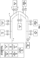
- FIG. 1 illustrates an embodiment of the microgrid EMS 100 and a microgrid controlled by the microgrid EMS 100.
- the microgrid includes distributed energy resources (DERs) and loads 102 within a local area.
- the loads 102 can be a single utility customer, a grouping of several sites, or dispersed sites that operate in a coordinated fashion.
- the DERs can include one or more distributed electric generators such as reciprocating engine generator(s) 104, microturbine(s) 106, fuel cell(s) 108, photovoltaic/solar generator(s) 110, wind turbine(s) 112, and other small-scale renewable generators, and also electrical energy storage devices 114.
- the DERs and loads 102 are interconnected by an electrical network 116.
- Each DER and load 102 can be connected to the electrical network 116 by a protection device (PD) 118 such as a fuse, circuit breaker, relay, step-down transformer, etc.
- the microgrid can be connected to a substation or a macrogrid 120 in a grid-connected mode.
- One or more points of common coupling (PCC) 122 can be provided for connecting the electrical network 116 of the microgrid to the substation or macrogrid 120.
- the microgrid can be isolated from all power grids, substations, etc. in an island mode by appropriate control of the PCC 122.
- All controllable DERs and loads 102 included in the microgrid are interconnected by a communications and control network 124 so that the controllable devices can perform certain microgrid control functions.
- the microgrid EMS 100 has remote or direct access to the communications and control network 124 of the microgrid, for controlling the DERs and loads 102 through local control agents (CA) 126.
- the microgrid EMS 100 comprises a processing circuit 128 which can include digital and/or analog circuitry such as one or more controllers, processors, ASICs (application-specific integrated circuits), etc. for executing program code which performs the energy management control operations described herein.
- the microgrid EMS 100 includes a DER schedule unit 130, an ED/OPF (economic dispatch / optimal power flow) unit 132 and an outage mitigation unit 133 included in or associated with the processing circuit 128 for performing the energy management control operations.
- the microgrid EMS 100 also has one or more storage media such as DRAM (dynamic random access memory) 134 and an HDD (hard disk drive) 136 for storing the program code and related data processed and accessed by the processing circuit 128, DER schedule unit 130, ED/OPF unit 132, and outage mitigation unit 133 during execution of program code.
- the storage medium also stores the results generated by the microgrid EMS 100.
- the microgrid EMS 100 also has I/O (input/output) circuitry 138 for communicating with the controllable DERs and loads 102 over the communications and control network 124 via the local control agents 126.
- I/O (input/output) circuitry 138 for communicating with the controllable DERs and loads 102 over the communications and control network 124 via the local control agents 126.
- the microgrid EMS 100 can receive renewable energy generation and load forecast information, DER power generation information and other information used in the energy management control operations via the I/O circuitry 138.
- the microgrid EMS 100 can also communicate power set points and other types of control information generated as part of the energy management control operations described herein to the controllable DERs and loads 102 via the I/O circuitry 138.
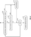
- Figure 2 illustrates a flow diagram of an embodiment of a method of controlling operation of a microgrid which comprises a plurality of distributed energy resources including controllable distributed electric generators and electrical energy storage devices.
- the method includes periodically updating a DER schedule for the microgrid (Block 200), e.g. by the DER schedule unit 130 of the microgrid EMS 100.
- the DER schedule includes the on/off status of the controllable distributed electric generators and charging/discharging status and rate of the electrical energy storage devices included in the microgrid.
- the on/off status of the controllable distributed electric generators indicates whether each controllable distributed electric generator is online (active) or offline (de-active).
- the charging/discharging status of the electrical energy storage devices indicates whether each electrical energy storage device is storing (charging) energy or releasing (discharging) energy.
- the rate indicates how quickly each electrical energy storage device charges or discharges energy.
- the DER schedule satisfies a first control objective for a defined time window e.g. 24 hours, and is determined based at least in part on a renewable energy generation and load forecast for the microgrid. Any standard methodology can be used to derive the renewable energy generation and load forecast.
- the method further includes periodically determining power set points for the controllable distributed energy resources which satisfy a second control objective for the present time interval within the defined time window (Block 210), e.g. by the ED/OPF unit 132 of the microgrid EMS 100.
- the second control objective is a function of at least the distributed energy resource schedule for the microgrid.
- Figure 3 illustrates an embodiment of the method of Figure 2 , implemented for an exemplary moving (sliding) 24 hour time window.
- the DER schedule for the controllable distributed electric generators and electrical energy storage devices included in the microgrid is updated every hour ('Hr 0', 'HR 1', ... , 'HR 23') based at least in part on the latest renewable energy generation and load forecast available for the microgrid.
- Each DER schedule update yields on/off status of the controllable distributed electric generators and charging/discharging status and rate of the electrical energy storage devices for the next 24 hour window i.e. the defined time window moves (slides) by one hour each update, but still looks out over a 24 hour window.
- the DER schedule is updated each time the renewable energy generation and load forecast is revised.
- the defined time window 24 hours in this example moves (slides) by a corresponding amount (1 hour in this example) each time the DER schedule is updated.
- power set points for the controllable distributed energy resources are determined so that a second control objective is satisfied for the present time interval within the 24 hour time window.
- the power set points can be determined e.g. every 5 to 15 minutes between DER schedule updates.
- the power set points can be updated multiple times during successive time intervals before the DER schedule is updated again and the defined time window is moved (shifted).
- the defined time window is shorter for the island mode than for the grid-connected mode. For example, a 24 hour time window may be used for the grid-connected mode and a 12 hour time window may be used for the island mode. In general, any defined time window can be used such as 48 hours, 36 hours, 24 hours, 12 hours, etc.
- the power set points for the controllable distributed energy resources can be determined for a present time interval of any desirable length within the defined time window e.g. every 5 to 15 minutes or more or less frequently.
- the DER schedule is updated every hour or less frequently and the power set points for the controllable distributed energy resources are determined every fifteen minutes or more frequently.
- a power balance approach can be used for periodically updating the DER schedule and an optimal power flow approach can be used for periodically determining the power set points of the controllable distributed energy resources.
- the DER schedule unit 130 included in or associated with the microgrid EMS 100 performs a forward-looking DER schedule function for implementing the operation planning that optimizes the DER schedule for a defined time window (e.g., 24 hours in the exemplary embodiment of Figure 3 ).
- the DER schedule function determines the on/off status of the controllable distributed electric generators (DG) included in the microgrid and the charging/discharging status and rate of the electrical energy storage devices (ES) included in the microgrid.
- the DER schedule function can be executed each time the renewable generation and/or load forecasting is updated, such as every one hour or every two hours.
- the DER schedule function In each execution, the DER schedule function considers the latest renewable generation/load forecast to determine the committed DGs and ESs for every preselected time interval (e.g., every 30 minutes) in the defined time window (e.g., 24 hours).
- the DER schedule function plans for enough spinning (working) reserve capacity for critical load(s) to improve the operation security in case of contingencies such as unplanned outage events.
- the DER schedule function also includes constraints such as power balance, DG/ES capacity, energy storage state of charge, etc.
- the formulation of the DER schedule function is presented next in more detail.
- the DER schedule unit 130 included in or associated with the microgrid EMS 100 implements the DER schedule function to generate a DER schedule that satisfies a control objective for the defined time window of interest.
- the control objective minimizes the operation cost of the microgrid over the defined time window.
- Microgrid operation cost constraints can include utility grid electricity price, distributed electric generator startup/shutdown/no-load/generation cost, energy storage costs, etc.
- the constraint set includes the constraints for power balance, generation power output, security, energy storage charge state (charging or discharging), energy storage charging/discharging rates, etc.
- the energy storage charging/discharging/stand-by efficiency can be assumed to be 100% and the costs associated with energy storage (e.g. startup/shutdown, charging/discharging, etc.) are assumed to prevent frequent charging and discharging of the electrical energy storage devices in order to prolong battery life.
- the charging and discharging operation costs of the electrical energy storage devices are used to prevent unexpected utilization of energy storage.
- the startup/shutdown costs of the electrical energy storage devices are used to prevent frequent charging and discharging.
- system loss is assumed to be a certain percentage of the overall loading level.
- the planning horizon of the DER schedule in the grid-connected mode is usually longer than that in the island mode. For instance in the grid-connected mode, the planning period can be chosen as 24 hours and in the island mode the period can be chosen as 12 hours or less.
- the control objective is also a function of the energy storage cost associated with the electrical energy storage devices.
- Equation (2) is a power balance equation which ensures the total generation is equal to total load demand in each decision time interval.
- a correction factor K2 can be set to a value other than one to adjust the power balance.
- Equation (3) represents the power output constraints for the controllable distributed electric generators.
- Equations (4) and (5) are constraints for start-up and shut-down operation of the distributed electric generators, respectively.
- Equation (6) is a security constraint which ensures that the total generation capacity of on-line (active) controllable distributed electric generators is larger than the total demand of the critical loads.
- the control objective ensures the total power generation capacity of all of the controllable distributed electric generators having an 'on' status as indicated by parameter S dg of the distributed energy resource schedule is greater than a critical load of the microgrid for the defined time window.
- a correction factor K 1 can be set to a value other than one to account for at least one of the 'on' controllable distributed electric generators being out of service during the defined time window. This way, the total power generation capacity remains greater than the critical load of the microgrid over the defined time window even if an unplanned outage happens such as the disconnection from the main grid (islanding) or one of the controllable distributed electric generators is out of service in island mode.
- Equation (7) is a renewable power output constraint for the renewable electric generators included in the microgrid.
- Equation (8) is the state of the charge constraint for the electrical energy storage devices included in the microgrid.
- Equation (9) is the charge or discharge constraint for the electrical energy storage devices, where the efficiency of charging/discharging is assumed to be 100%.
- Equation (10) is a constraint for the electrical energy storage devices between the charging/discharging rate and the status.
- Equation (11) is an energy storage charging/discharging status constraint.
- Equations (12) and (13) are constraints related to energy storage start-up charging/discharging operation.
- u DER P gd ⁇ U dg ⁇ 1 U dg ⁇ 2 ⁇ U dg ⁇ n dg ⁇ U es ⁇ 1 U es ⁇ 2 ⁇ U es ⁇ n es ⁇ U es ⁇ C U es ⁇ D
- the DER schedule function can be formulated as a mixed integer linear programming problem.
- the control variables include both continuous and binary variables.
- the continuous control variables include P gd , P dg , and P es .
- the binary control variables (0 or 1) include S dg , SU dg , SD dg , S es , S es C , S es D , SU es C , SU es D .
- the input information for DER schedule function includes:
- the output of the DER schedule function is a DER schedule including: the on/off status of the controllable distributed electric generators, renewable power output (when renewable is on/off or continuously controllable), and the charging/discharging/idle status and rate of the electrical energy storage devices.
- the DER schedule is used by the ED/OPF unit 132 of the microgrid EMS 100 to determine the power set points of the distributed energy resources in real-time operation.
- the ED/OPF unit 132 minimizes the operation cost of the microgrid for the present time interval (e.g., 5 to 15 minutes) while minimizing the deviation of the energy storage charging/discharging rate. That is, the control objective minimizes the extent by which the actual charging/discharging rate of the electrical energy storage devices deviates from the charging/discharging rate identified for the electrical energy storage devices in the distributed energy resource schedule.
- the constraints considered by the ED/OPF unit 132 include power balance, ramping rate, energy storage charging/discharging efficiencies, as well as operating constraints such as line current and node voltage limits in case a detailed network model is available for the microgrid.
- Equation (15) is an objective function implemented by the ED/OPF unit 132 that minimizes operation cost of the microgrid.
- Equation (16) is a power balance equation which ensures total load demand is supplied from generation.
- a loss coefficient K 2 accounts for planned outages in the microgrid so that load shedding can be minimized over the present time interval i.e. by setting K 2 > 1 e.g.
- Equation (17) defines an operating range on the upper and lower limits of DG active power.
- Equation (18) provides DG real (P) power output ramp rate constraints.
- Equation (19) provides electrical energy storage device charging/discharging rate constraints.
- Equation (20) provides electrical energy storage device state (i.e. charging or discharging) constraints.
- Equations (21) and (22) provide line current and node voltage constraints, respectively, when a detailed network model is available for the microgrid.
- the line current and node voltage constraints can include line current and node voltage sensitivity variables, respectively.
- Equation (23) defines an operating range on the upper and lower limits of DG reactive (Q) power or the voltage setting point.
- control variables of the ED/OPF function are as follows:
- u ED / OPF [ P dg ⁇ P es ⁇ Q ⁇ dg ]
- P dg P dg ⁇ 1 P dg ⁇ 2 ... ... . . P dg ⁇ n dg
- P es P es ⁇ 1 P es ⁇ 2 ... ... . . P es ⁇ n es
- Q ⁇ dg Q dg ⁇ 2 ⁇ ⁇ ⁇ Q dg ⁇ dg ]
- Distributed electric generator DG1 for example the electric generator with the largest capacity, is chosen as a slack generator in island mode.
- the reactive power (Q) of DG1 is determined by the total load demand and power outputs of the other distributed electric generators.
- the ED/OPF unit 132 formulates the ED/OPF as a quadratic programming problem.
- a quadratic term is included in the objective function given by equation (15). All the constraints are linear expressions.
- the input information for ED/OPF objective function includes:
- the output of ED/OPF objective function includes power set points for the controllable distributed energy resources and energy storage charging/discharging power. Theses control demands can be issued to corresponding devices to operate the microgrid every time interval in operational real time, via the microgrid communications and control network 124.
- power outages can be mitigated by the outage mitigation unit 133 of the microgrid EMS 100 e.g. by setting the loss coefficient K 2 appropriately. For planned outages, a more precise and robust solution is provided.
- Figure 4 illustrates a flow diagram of an embodiment of a method of controlling operation of a microgrid which comprises a plurality of distributed energy resources including controllable distributed electric generators and electrical energy storage devices.
- the DER schedule unit 130 of the microgrid EMS 100 executes the DER objective function to update the DER schedule (Block 310) e.g. in accordance with equations (1)-(14).
- the ED/OPF unit 132 executes the ED/OPF objective function based in part on the new DER schedule to determine new power set points for the controllable distributed energy resources (Block 320) e.g. in accordance with equations (15)-(23).
- the microgrid EMS 100 executes the DER objective function at the normally scheduled interval (e.g. every 1 or 2 hours, with a 24 hour forward-looking window) and then executes the ED/OPF objective function based in part on the new (regularly scheduled) DER schedule (Blocks 330, 320).
- the normally scheduled interval e.g. every 1 or 2 hours, with a 24 hour forward-looking window
- the ED/OPF objective function based in part on the new (regularly scheduled) DER schedule (Blocks 330, 320).
- the DER schedule can plan for enough spinning (working) reserve for the critical loads.
- both the local control of DG/ES and load shedding mechanism respond automatically to the frequency/voltage variation to adjust the generation output and/or conduct load shedding.
- the microgrid EMS can implement a planned outage control function (Block 340).
- the microgrid EMS can implement the planned outage control function to determine the load shedding in advance.
- the DER and ED/OPF objective functions can be executed to determine the load shedding as well as power generation re-dispatch among the available distributed electric generators, for instance, to reach zero power exchange with the utility before entering island mode.
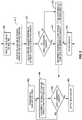
- Figure 5 illustrates a flow diagram of an embodiment of a planned outage control function implemented by the outage mitigation unit 133 of the microgrid EMS 100.
- the planned outage control function considers a worst-case scenario during an outage. The amount of load shedding is determined based on the maximum mismatch of the generation and load. The load shedding solution is the same during each outage.
- the planned outage control function uses the planned outage time/schedule (Block 400) and the load demand/renewable generation forecast over the estimated outage duration (Block 410) to calculate whether load shedding is necessary and if so how much load should be shed (Block 420).
- load shedding is not required (Block 430)
- no loads are disconnected (Block 440) and the result is output (Block 450). Otherwise, non-critical loads are prioritized and shed before the outage occurs (Block 460).
- This can include determining the load shedding list based on heuristic rules so that no optimization is required. This solution is applicable when the estimated outage duration is relatively short such as less than 4 hours.
- the non-critical loads are prioritized (Block 462) and the smallest non-critical load is disconnected and removed from the load shedding list (Block 464). If the load capacity remains above the generation capacity after this modification of the load shedding list (Block 466), the next smallest non-critical load is disconnected and removed from the load shedding list (Block 464). This process is repeated until the load capacity is at or below the generation capacity (Blocks 464, 466) or some other stopping criteria is satisfied. The new load shedding list is output (Block 468) for use during the scheduled outage.
- the entire duration of the outage is considered rather than the worst-case scenario.
- Operation of the microgrid is also optimized over a time horizon to calculate the DER status and energy storage set points as well as the amount of load shedding in each decision time interval.
- This formulation is the same as DER schedule function embodiments previously described herein, except load shedding is included. After the amount of load shedding in each interval is determined, a new load shedding list is generated based on the priority of non-critical loads for each time interval. Non-critical loads are shed based on the load shedding list in each decision interval. As such, load shedding is considered over the outage duration which helps to minimize the adverse effects of load shedding.
- Equation (24) minimizes the operation cost of the microgrid and also minimizes load shedding over the outage duration. Equation (25) ensures that the generation and load are balanced in each time interval. Equation (26) ensures that the amount of load shedding is always positive. Equations (27)-(37) correspond to equations (3)-(13) relating to the DER schedule function.
- u DER U dg ⁇ 1 U dg ⁇ 2 ⁇ U dg ⁇ n dg ⁇ U es ⁇ 1 U es ⁇ 2 ⁇ U es ⁇ n es ⁇ U es ⁇ C U es ⁇ D ⁇ U shed
- the planned outage control is formulated by the outage mitigation unit 133 of the microgrid EMS 100 as a mixed integer linear programming problem.
- the control variables include both continuous and binary variables.
- Continuous control variables include: P gd ; P dg ; P es ; and P shed .
- Binary control variables (0 or 1) include: S dg ; SU dg ; SD dg S es ; S es C ; S es D ; SU es C ; SU es D .
- Information input for the planned outage control includes:
- the output of the planned outage control function includes: the on/off status of controllable distributed electric generators, renewable power output (when renewable is continuously controllable), charging/discharging/idle status and rate of electrical energy storage devices and a load shedding list.
- the microgrid EMS 100 described herein can execute in a central controller of a distributed control system (DCS) and collect information from across the entire microgrid.
- DCS distributed control system
- stability is not a major issue while the main objective is to achieve economic operation of the microgrid.
- the local stability control (V/f) is disabled and all units operate in the so-called PQ mode with settings provided by the microgrid 100 EMS unless the microgrid provides ancillary services such as frequency control and voltage regulation to the grid operator.
- One or more fast responsive DERs such as flywheels can be controlled to respond to system frequency and voltage variation, while the microgrid EMS 100 provides power set points for other energy resources in the desired time interval (e.g. every 5 to 15 minutes) to improve system economic operation.
- the main objective for microgrid operation is to maintain system stability and guarantee the critical load service, based on which economic operation can be further achieved.
- the microgrid EMS 100 can provide power set points as a point of reference to the decisions made by the DC
- the methodologies described herein move operational planning from day-ahead to an hour(s) ahead time frame, which enables the DER schedule to take full advantage of the latest and most accurate generation and load forecasting information.
- the proposed DER schedule function can determine the commitment of the DERs in a shorter time length (e.g., every 30 minutes) according to the microgrid scale.
- microgrid EMS 100 described herein solves the DER schedule when the renewable generation and load forecast is updated and implements the ED/OPF for the present time interval to reduce computational complexity. This allows the incorporation of more detailed operating constraints such as line current and bus voltage constraints i.e. optimal power flow constraints.
- the execution frequency of the DER schedule can also be adjusted by the scale of the microgrid or the dimension of the optimization problem to be solved. For example, if the optimization problem can be solved fast enough, then the execution of the DER schedule can be done each time when an update in the generation and/or load forecast occurs. Otherwise, the DER schedule can be executed only if there is a change greater than a certain pre-defined threshold.
Landscapes
- Engineering & Computer Science (AREA)
- Power Engineering (AREA)
- Health & Medical Sciences (AREA)
- Artificial Intelligence (AREA)
- Computer Vision & Pattern Recognition (AREA)
- Evolutionary Computation (AREA)
- Medical Informatics (AREA)
- Software Systems (AREA)
- Physics & Mathematics (AREA)
- General Physics & Mathematics (AREA)
- Automation & Control Theory (AREA)
- Supply And Distribution Of Alternating Current (AREA)
- Crystals, And After-Treatments Of Crystals (AREA)
- Exhaust-Gas Circulating Devices (AREA)
Claims (23)
- Verfahren zum Steuern des Betriebs eines Mikrostromnetzes, das eine Mehrzahl von verteilten Energieressourcen umfasst, die steuerbare verteilte elektrische Generatoren (104, 106, 108, 110, 112) und elektrische Energiespeichervorrichtungen (114) aufweisen, das Verfahren umfassend:periodisches Aktualisieren eines Zeitplans der verteilten Energieressourcen für das Mikrostromnetz, der einen Ein-/Aus-Zustand der steuerbaren verteilten elektrischen Generatoren (104, 106, 108, 110, 112) und einen Lade-/Entlade-Zustand und eine Lade-/Entlade-Rate der elektrischen Energiespeichervorrichtungen (114) aufweist und der ein erstes Steuerziel für ein definiertes Zeitfenster, basierend zumindest teilweise auf einer erneuerbaren Energieerzeugung und Last-Prognose für das Mikrostromnetz (200), erfüllt; undperiodisches Bestimmen von Leistungssollwerten für die Mehrzahl von verteilten Energieressourcen (104, 106, 108, 110, 112, 114), die ein zweites Steuerziel für ein gegenwärtiges Zeitintervall innerhalb des definierten Zeitfensters, erfüllt, wobei das zweite Steuerziel eine Funktion von zumindest dem Zeitplan der verteilten Energieressourcen für das Mikrostromnetz (210),dadurch gekennzeichnet, dassdie Leistungssollwerte für die Mehrzahl von verteilten Energieressourcen (104, 106, 108, 110, 112, 114) für zumindest zwei aufeinanderfolgende Zeitintervalle innerhalb des definierten Zeitfensters bestimmt werden, bevor der Zeitplan der verteilten Energieressourcen wieder aktualisiert wird und das definierte Zeitfenster bewegt wird.
- Verfahren nach Anspruch 1, wobei das erste Steuerziel auch eine Funktion von Energiespeicherkosten ist, die den elektrischen Energiespeichervorrichtungen (114) zugeordnet sind.
- Verfahren nach Anspruch 2, wobei das erste Steuerziel die Menge des Ladens/Entladens, die für die elektrischen Energiespeichervorrichtungen (114) über das definierte Zeitfenster zulässig ist, limitiert, sodass die Energiespeicherkosten für das definierte Zeitfenster minimiert werden.
- Verfahren nach Anspruch 1, wobei das erste Steuerziel gewährleistet, dass eine Gesamtstromerzeugungskapazität von allen den steuerbaren verteilten elektrischen Generatoren (104, 106, 108, 110, 112), die einen Ein-Zustand aufweisen, wie von dem Zeitplan der verteilten Energieressourcen angezeigt, größer ist, als eine kritische Last des Mikrostromnetzes für das definierte Zeitfenster.
- Verfahren nach Anspruch 4, wobei das erste Steuerziel auch eine Funktion von einem Korrekturfaktor ist, der zumindest einen der steuerbaren verteilten elektrischen Generatoren (104, 106, 108, 110, 112) mit einem Ein-Status berücksichtigt, der während des definierten Zeitfensters außer Betrieb ist, sodass die Gesamtstromerzeugungskapazität über das definierte Zeitfenster größer bleibt, als die kritische Last des Mikrostromnetzes, selbst wenn das Mikrostromnetz von einen Hauptstromnetz getrennt ist oder zumindest einer der steuerbaren verteilten elektrischen Generatoren (104, 106, 108, 110, 112) in einem Inselmodus außer Betrieb ist.
- Verfahren nach Anspruch 1, wobei das Mikrostromnetz ausgebildet ist, um in einem netzgekoppelten Modus mit Stromnetzen verbunden zu werden und in einem Inselmodus von allen Stromnetzen isoliert zu werden, und wobei das definierte Zeitfenster für den Inselmodus kürzer ist, als für den netzgekoppelten Modus.
- Verfahren nach Anspruch 1, weiterhin umfassend:Aktualisieren des Zeitplans der verteilten Energieressourcen jedes Mal, wenn die erneuerbare Energieerzeugung und die Last-Prognose korrigiert wird; undBewegen des definierten Zeitfensters jedes Mal, wenn der Zeitplan der verteilten Energieressourcen aktualisiert wird.
- Verfahren nach Anspruch 1, wobei der Zeitplan der verteilten Energieressourcen jede Stunde oder weniger häufig aktualisiert wird, und wobei die Leistungssollwerte für die Mehrzahl von verteilten Energieressourcen (104, 106, 108, 110, 112, 114) alle fünfzehn Minuten oder häufiger bestimmt werden.
- Verfahren nach Anspruch 1, wobei das zweite Steuerziel Betriebskosten für das Mikrostromnetz des gegenwärtigen Zeitintervalls minimiert, während das Ausmaß, um welches die tatsächliche Lade-/Entlade-Rate der elektrischen Energiespeichervorrichtungen (114) von der Lade-/Entlade-Rate abweicht, die für die elektrischen Energiespeichervorrichtungen (114) in dem Zeitplan der verteilten Energieressourcen identifiziert wird.
- Verfahren nach Anspruch 1, wobei das zweite Steuerziel eine Funktion von Leitungsstrom- und Knotenspannungs-Beschränkungen ist, die dem Mikrostromnetz auferlegt sind.
- Verfahren nach Anspruch 1, wobei das zweite Steuerziel auch eine Funktion eines Wichtungsfaktors ist, der auf die für die elektrischen Energiespeichervorrichtungen (114) in dem Zeitplan der verteilten Energieressourcen identifizierten Lade-/Entlade-Rate angewandt wird.
- Verfahren nach Anspruch 1, wobei das zweite Steuerziel auch eine Funktion einer Lastabschaltungsvariablen ist, die geplante Ausfälle in dem Mikrostromnetz berücksichtigt, sodass Lastabschaltung über das gegenwärtige Zeitintervall minimiert wird.
- Mikrostromnetz-Energieverwaltungssystem (100) zum Steuern des Betriebs eines Mikrostromnetzes, das eine Mehrzahl von verteilten Energieressourcen umfasst, die steuerbare verteilte elektrische Generatoren (104, 106, 108, 110, 112) und elektrische Energiespeichervorrichtungen (114) aufweisen, das Mikrostromnetz-Energieverwaltungssystem (100) umfassend eine Verarbeitungsschaltung (128), betreibbar zum:periodischen Aktualisieren eines Zeitplans der verteilten Energieressourcen für das Mikrostromnetz, der einen Ein-/Aus-Zustand der steuerbaren verteilten elektrischen Generatoren (104, 106, 108, 110, 112) und einen Lade-/Entlade-Zustand und eine Lade-/Entlade-Rate der elektrischen Energiespeichervorrichtungen (114) aufweist und der ein erstes Steuerziel für ein definiertes Zeitfenster, basierend zumindest teilweise auf einer erneuerbaren Energieerzeugung und Last-Prognose für das Mikrostromnetz , erfüllt; undperiodischen Bestimmen von Leistungssollwerten für die Mehrzahl von verteilten Energieressourcen (104, 106, 108, 110, 112, 114), die ein zweites Steuerziel für ein gegenwärtiges Zeitintervall innerhalb des definierten Zeitfensters, erfüllt, wobei das zweite Steuerziel eine Funktion von zumindest dem Zeitplan der verteilten Energieressourcen für das Mikrostromnetz,dadurch gekennzeichnet, dass die Verarbeitungsschaltung (128) betreibbar ist, zum Bestimmen der Leistungssollwerte für die Mehrzahl von verteilten Energieressourcen (104, 106, 108, 110, 112, 114) für zumindest zwei aufeinanderfolgende Zeitintervalle innerhalb des definierten Zeitfensters, bevor der Zeitplan der verteilten Energieressourcen wieder aktualisiert wird und das definierte Zeitfenster bewegt wird.
- Mikrostromnetz-Energieverwaltungssystem (100) nach Anspruch 13, wobei das erste Steuerziel auch eine Funktion von Energiespeicherkosten ist, die den elektrischen Energiespeichervorrichtungen (114) zugeordnet sind.
- Mikrostromnetz-Energieverwaltungssystem (100) nach Anspruch 14, wobei das erste Steuerziel die Menge des Ladens/Entladens, die für die elektrischen Energiespeichervorrichtungen (114) über das definierte Zeitfenster zulässig ist, limitiert, sodass die Energiespeicherkosten für das definierte Zeitfenster minimiert werden.
- Mikrostromnetz-Energieverwaltungssystem (100) nach Anspruch 13, wobei das erste Steuerziel gewährleistet, dass eine Gesamtstromerzeugungskapazität von allen den steuerbaren verteilten elektrischen Generatoren (104, 106, 108, 110, 112), die einen Ein-Zustand aufweisen, wie von dem Zeitplan der verteilten Energieressourcen angezeigt, größer ist, als eine kritische Last des Mikrostromnetzes für das definierte Zeitfenster.
- Mikrostromnetz-Energieverwaltungssystem (100) nach Anspruch 16, wobei das erste Steuerziel auch eine Funktion von einem Korrekturfaktor ist, der Trennung von Stromnetzen oder zumindest einen der steuerbaren verteilten elektrischen Generatoren (104, 106, 108, 110, 112, 114) mit einem Ein-Zustand, der während des definierten Zeitfensters außer Betrieb ist, berücksichtigt, sodass die Gesamtstromerzeugungskapazität über das definierte Zeitfenster größer bleibt, als die kritische Last des Mikrostromnetzes, selbst wenn die Stromnetze oder der zumindest eine steuerbare verteilte elektrische Generator (104, 106, 108, 110, 112) in einem Inselmodus außer Betrieb ist.
- Mikrostromnetz-Energieverwaltungssystem (100) nach Anspruch 13, wobei die Verarbeitungsschaltung (128) weiterhin betreibbar ist, zum:Aktualisieren des Zeitplans der verteilten Energieressourcen jedes Mal, wenn die erneuerbare Energieerzeugung und die Last-Prognose korrigiert wird; undBewegen des definierten Zeitfensters jedes Mal, wenn der Zeitplan der verteilten Energieressourcen aktualisiert wird.
- Mikrostromnetz-Energieverwaltungssystem (100) nach Anspruch 13, wobei die Verarbeitungsschaltung (128) betreibbar ist, zum Aktualisieren des Zeitplans der verteilten Energieressourcen jede Stunde oder weniger häufig, und zum Bestimmen der Leistungssollwerte für die Mehrzahl von verteilten Energieressourcen (104, 106, 108, 110, 112, 114) alle fünfzehn Minuten oder häufiger.
- Mikrostromnetz-Energieverwaltungssystem (100) nach Anspruch 13, wobei das zweite Steuerziel Betriebskosten für das Mikrostromnetz des gegenwärtigen Zeitintervalls minimiert, während das Ausmaß, um welches die tatsächliche Lade-/Entlade-Rate der elektrischen Energiespeichervorrichtungen (114) von der Lade-/Entlade-Rate abweicht, die für die elektrischen Energiespeichervorrichtungen (114) in dem Zeitplan der verteilten Energieressourcen identifiziert wird.
- Mikrostromnetz-Energieverwaltungssystem (100) nach Anspruch 13, wobei das zweite Steuerziel eine Funktion von Leitungsstrom- und Knotenspannungs-Beschränkungen ist, die dem Mikrostromnetz auferlegt sind.
- Mikrostromnetz-Energieverwaltungssystem (100) nach Anspruch 13, wobei das zweite Steuerziel auch eine Funktion eines Wichtungsfaktors ist, der auf die für die elektrischen Energiespeichervorrichtungen (114) in dem Zeitplan der verteilten Energieressourcen identifizierten Lade-/Entlade-Rate angewandt wird.
- Mikrostromnetz-Energieverwaltungssystem (100) nach Anspruch 13, wobei das zweite Steuerziel auch eine Funktion einer Lastabschaltungsvariablen ist, die geplante Ausfälle in dem Mikrostromnetz berücksichtigt, sodass Lastabschaltung über das gegenwärtige Zeitintervall minimiert wird.
Applications Claiming Priority (2)
| Application Number | Priority Date | Filing Date | Title |
|---|---|---|---|
| US13/955,575 US9733623B2 (en) | 2013-07-31 | 2013-07-31 | Microgrid energy management system and method for controlling operation of a microgrid |
| PCT/US2014/047736 WO2015017201A1 (en) | 2013-07-31 | 2014-07-23 | Microgrid energy management system and method for controlling operation of a microgrid |
Publications (3)
| Publication Number | Publication Date |
|---|---|
| EP3028358A1 EP3028358A1 (de) | 2016-06-08 |
| EP3028358B1 true EP3028358B1 (de) | 2017-04-26 |
| EP3028358B2 EP3028358B2 (de) | 2023-04-26 |
Family
ID=51301351
Family Applications (1)
| Application Number | Title | Priority Date | Filing Date |
|---|---|---|---|
| EP14750273.6A Active EP3028358B2 (de) | 2013-07-31 | 2014-07-23 | Steuersystem und verfahren für ein mikrostromnetz |
Country Status (8)
| Country | Link |
|---|---|
| US (1) | US9733623B2 (de) |
| EP (1) | EP3028358B2 (de) |
| CN (1) | CN105684257B (de) |
| AU (1) | AU2014296613B2 (de) |
| ES (1) | ES2637967T5 (de) |
| PT (1) | PT3028358T (de) |
| WO (1) | WO2015017201A1 (de) |
| ZA (1) | ZA201600139B (de) |
Cited By (3)
| Publication number | Priority date | Publication date | Assignee | Title |
|---|---|---|---|---|
| DE102020104324A1 (de) | 2020-02-19 | 2021-08-19 | Fraunhofer-Gesellschaft zur Förderung der angewandten Forschung e.V. | Verfahren zum Betreiben eines elektrischen Inselstromnetzes |
| US12015275B2 (en) | 2018-12-12 | 2024-06-18 | General Electric Company | Hybrid power plant |
| EP4622041A1 (de) * | 2024-03-21 | 2025-09-24 | Abb Schweiz Ag | Energieverwaltungssysteme, vorrichtungen und verfahren zum virtuellen inselmachen eines mikronetzes |
Families Citing this family (91)
| Publication number | Priority date | Publication date | Assignee | Title |
|---|---|---|---|---|
| US20120271576A1 (en) | 2011-04-22 | 2012-10-25 | Expanergy, Llc | Systems and methods for analyzing energy usage |
| CN104303203B (zh) | 2011-11-28 | 2018-04-13 | 艾克潘尔基公司 | 能源搜索引擎方法及系统 |
| US9312699B2 (en) | 2012-10-11 | 2016-04-12 | Flexgen Power Systems, Inc. | Island grid power supply apparatus and methods using energy storage for transient stabilization |
| US10289080B2 (en) | 2012-10-11 | 2019-05-14 | Flexgen Power Systems, Inc. | Multi-generator applications using variable speed and solid state generators for efficiency and frequency stabilization |
| US9553517B2 (en) | 2013-03-01 | 2017-01-24 | Fllexgen Power Systems, Inc. | Hybrid energy storage system and methods |
| US9515491B2 (en) | 2013-09-18 | 2016-12-06 | International Business Machines Corporation | Managing devices within micro-grids |
| US10120358B2 (en) * | 2013-12-10 | 2018-11-06 | Nec Corporation | Energy system and method for controlling load balancing therein |
| US20150288183A1 (en) | 2014-04-06 | 2015-10-08 | CleanSpark Technologies LLC | Establishing communication and power sharing links between components of a distributed energy system |
| EP3134950B1 (de) * | 2014-04-22 | 2019-04-03 | Siemens Aktiengesellschaft | Flexible steuerungsarchitektur für mikronetzelastizität |
| US10623436B2 (en) * | 2014-04-28 | 2020-04-14 | Honeywell International Inc. | System and method of architectural security and resilience for microgrid systems |
| US20150311713A1 (en) * | 2014-04-28 | 2015-10-29 | Nec Laboratories America, Inc. | Service-based Approach Toward Management of Grid-Tied Microgrids |
| WO2015175362A1 (en) * | 2014-05-10 | 2015-11-19 | Scuderi Group, Inc. | Power generation systems and methods |
| AU2014409485A1 (en) * | 2014-10-21 | 2017-05-11 | Accenture Global Services Limited | System, method, and apparatus for capacity determination for micro grid, and tangible computer readable medium |
| US10468888B2 (en) * | 2014-12-17 | 2019-11-05 | Toshiba Mitsubishi-Electric Industrial Systems Corporation | Control system for solar power plant |
| CN107534294B (zh) | 2014-12-30 | 2021-07-30 | 弗莱斯金电力系统公司 | 具有有功和无功功率控制的暂态功率稳定化设备 |
| ES2720361T3 (es) | 2015-02-20 | 2019-07-19 | Maersk Drilling As | Sistema de generación y distribución de energía para unidades de perforación marítima |
| EP3308223A4 (de) * | 2015-06-12 | 2019-02-27 | United Technologies Corporation | Mikronetzsystem und steuergerät |
| US20170025894A1 (en) * | 2015-07-04 | 2017-01-26 | Sunverge Energy, Inc. | Microgrid controller for distributed energy systems |
| US9960637B2 (en) | 2015-07-04 | 2018-05-01 | Sunverge Energy, Inc. | Renewable energy integrated storage and generation systems, apparatus, and methods with cloud distributed energy management services |
| CN105515027B (zh) * | 2015-08-06 | 2017-03-29 | 樊朝晖 | 一种负荷曲线可配置的储能微网控制方法 |
| JP6420912B2 (ja) * | 2015-08-12 | 2018-11-07 | 京セラ株式会社 | 管理サーバ、管理方法及び管理システム |
| KR101724893B1 (ko) * | 2015-09-08 | 2017-04-07 | 한국전력공사 | 독립형 마이크로그리드 자율제어 시스템 및 방법 |
| US10366459B2 (en) | 2015-10-16 | 2019-07-30 | Andrija Sadikovic | Method and system for aggregation and control of energy grids with distributed energy resources |
| TWI559250B (zh) * | 2015-10-16 | 2016-11-21 | 行政院原子能委員會核能研究所 | 微電網能源管理即時調度方法 |
| WO2017067585A1 (en) * | 2015-10-21 | 2017-04-27 | Abb Schweiz Ag | A method to improve microgrid stability with mgc controllers |
| TWI553997B (zh) * | 2015-11-04 | 2016-10-11 | 元智大學 | 微電網最大裝設充電站容量評估方法及其系統 |
| JP6766822B2 (ja) * | 2015-11-26 | 2020-10-14 | 日本電気株式会社 | 情報処理装置、情報処理方法、及び、プログラム |
| US10437214B1 (en) * | 2015-12-04 | 2019-10-08 | University Of South Florida | Multi-agent decision making system for economic operation and frequency regulation |
| US10886737B2 (en) | 2016-01-25 | 2021-01-05 | S&C Electric Company | Energization control for establishing microgrids |
| CN108701999B (zh) * | 2016-03-03 | 2020-07-28 | Abb电网瑞士股份公司 | 微电网的功率控制 |
| WO2017154116A1 (ja) * | 2016-03-08 | 2017-09-14 | 日本電気株式会社 | 電力制御装置、電力制御システム、電力制御方法、及び、プログラム |
| US10423185B2 (en) * | 2016-05-09 | 2019-09-24 | General Electric Company | Systems and methods for regulating a microgrid |
| CN106026152B (zh) * | 2016-05-19 | 2017-06-06 | 合肥工业大学 | 一种电动汽车接入微电网的充放电调度方法 |
| US10191506B2 (en) * | 2016-09-29 | 2019-01-29 | Enel X North America, Inc. | Demand response dispatch prediction system including automated validation, estimation, and editing rules configuration engine |
| US10516269B2 (en) | 2016-11-16 | 2019-12-24 | Alliance For Sustainable Energy, Llc | Real time feedback-based optimization of distributed energy resources |
| US10418822B2 (en) * | 2017-02-14 | 2019-09-17 | Mitsubishi Electric Research Laboratories, Inc. | Energy production and frequency regulation Co-optimization for power generation systems |
| HUP1700091A2 (en) * | 2017-02-28 | 2018-09-28 | Imre Sziszak | Sheath means and method of forming a pavement with said sheath means |
| US10423138B2 (en) | 2017-03-06 | 2019-09-24 | Con Edison Battery Storage, Llc | Building energy storage system with planning tool |
| CN106998077A (zh) * | 2017-03-09 | 2017-08-01 | 国网新疆电力公司 | 一种长距离输电型电网光伏最大消纳能力的确定方法 |
| CN106953318A (zh) * | 2017-03-29 | 2017-07-14 | 杭州赫智电子科技有限公司 | 一种基于成本的微电网优化控制方法 |
| EP3386058A1 (de) * | 2017-04-04 | 2018-10-10 | ABB S.p.A. | Computerimplementiertes verfahren zur konfigurierung eines lastabwurfsteuergeräts |
| GB2578005A (en) * | 2017-04-07 | 2020-04-15 | Nexant Inc | Systems and methods for optimally delivering electrical energy in a network |
| US10613492B2 (en) | 2017-07-26 | 2020-04-07 | General Electric Company | Method and system for providing flexible reserve power for power grid |
| WO2019071154A1 (en) * | 2017-10-06 | 2019-04-11 | Proterra Inc. | CHARGE IN DEPOSIT OF A FLEET OF ELECTRIC VEHICLES |
| EP3487027B1 (de) * | 2017-11-21 | 2022-04-27 | Schneider Electric Industries SAS | Verfahren zur steuerung eines mikronetzes |
| US11223206B2 (en) | 2017-12-01 | 2022-01-11 | Massachusetts Institute Of Technology | Methods and systems for secure scheduling and dispatching synthetic regulation reserve from distributed energy resources |
| US10535998B2 (en) * | 2017-12-06 | 2020-01-14 | Inventus Holdings, Llc | Controlling a behind the meter energy storage and dispatch system to improve power efficiency |
| CN108695871B (zh) * | 2018-05-03 | 2021-07-06 | 上海交通大学 | 含有电力弹簧的孤岛微电网降低储能容量需求的配置方法 |
| US20200021131A1 (en) * | 2018-07-16 | 2020-01-16 | Battelle Memorial Institute | Control for energy resources in a microgrid |
| US10326305B1 (en) * | 2018-08-27 | 2019-06-18 | Ekergy Llc | Personal power plant system and methods of inverse energy generation |
| WO2020055411A1 (en) | 2018-09-13 | 2020-03-19 | General Electric Company | Systems and methods for rapidly responding to commanded power profiles |
| US12360504B2 (en) | 2018-09-14 | 2025-07-15 | Ge Grid Solutions Llc | Methods and systems for energy storage dispatch |
| DE102018124618A1 (de) * | 2018-10-05 | 2020-04-09 | Innogy Se | Steuerung und/oder Regelung von Micro-Grids |
| DE102018125529A1 (de) * | 2018-10-15 | 2020-04-16 | Wobben Properties Gmbh | Dynamisches Windkraftwerk |
| CN110046780B (zh) * | 2018-11-16 | 2022-11-11 | 国网浙江平阳县供电有限责任公司 | 基于分时电价的孤岛微电网需求响应经济调度方法及系统 |
| ES2931500T3 (es) * | 2018-12-03 | 2022-12-30 | Siemens Ag | Planificación operativa predictiva en una microrred con intercambio de potencia entre la microrred y una red eléctrica principal |
| CN110417018B (zh) * | 2018-12-14 | 2024-08-09 | 特变电工西安电气科技有限公司 | 一种多应用模式的并网型微电网能量管理方法及装置 |
| EP3700043B1 (de) * | 2019-02-22 | 2023-12-06 | Hitachi Energy Ltd | Verfahren zur steuerung eines mikronetzes, leistungsverwaltungssystem und energieverwaltungssystem |
| CN109919478B (zh) * | 2019-02-28 | 2023-04-07 | 天津大学 | 一种考虑综合供能可靠性的综合能源微网规划方法 |
| CN110048405B (zh) * | 2019-04-03 | 2023-03-28 | 上海交通大学 | 基于电力弹簧的微电网能量优化方法 |
| CN110310014B (zh) * | 2019-06-05 | 2022-05-03 | 清华大学 | 基于过渡矩阵的泛在电力物联网分布式经济调度方法 |
| CN110417002B (zh) * | 2019-07-09 | 2021-02-12 | 华中科技大学 | 一种孤岛微电网能量模型的优化方法 |
| CN110390598B (zh) * | 2019-09-05 | 2024-04-26 | 珠海格力电器股份有限公司 | 能源交易系统、控制方法以及存储介质 |
| CN110571868B (zh) * | 2019-09-25 | 2023-06-02 | 三峡大学 | 微电网的优化配置方法 |
| CN110707712B (zh) * | 2019-10-15 | 2022-10-28 | 东北大学 | 一种考虑需求响应的微电网供电可靠性分析方法 |
| CN110826239A (zh) * | 2019-11-12 | 2020-02-21 | 东南大学 | 一种冷热电联供型多微网主动配电系统调度方法 |
| CN111064210B (zh) * | 2019-12-12 | 2021-09-14 | 国网浙江省电力有限公司台州供电公司 | 增加新能源发电波动的海岛电网储能系统分层控制方法 |
| US11824359B2 (en) * | 2020-01-28 | 2023-11-21 | Electronics And Telecommunications Research Institute | Electricity management apparatus for trading dump power for housing, and housing complex association method |
| US11244410B2 (en) * | 2020-02-24 | 2022-02-08 | Leading Edge Power Solutions, Llc | Technologies for dynamically dispatching generator power |
| US12444948B2 (en) * | 2020-08-20 | 2025-10-14 | Ihi Corporation | Demand and supply planning method and demand and supply planning apparatus |
| JP7514748B2 (ja) * | 2020-12-04 | 2024-07-11 | 株式会社日立製作所 | 電力系統運用計画作成支援装置および方法 |
| WO2022136186A1 (en) * | 2020-12-21 | 2022-06-30 | Hitachi Energy Switzerland Ag | Power grid resource allocation |
| US11630429B2 (en) * | 2020-12-21 | 2023-04-18 | Hitachi Energy Switzerland Ag | Power grid resource allocation |
| JP7494729B2 (ja) * | 2020-12-23 | 2024-06-04 | トヨタ自動車株式会社 | 電力システムおよびサーバ |
| CN112785048B (zh) * | 2021-01-07 | 2023-09-08 | 太原理工大学 | 计及电动汽车用户需求的直流微电网经济调度方法 |
| CN112928767B (zh) * | 2021-03-29 | 2022-06-14 | 广东电网有限责任公司电力科学研究院 | 一种分布式储能协同控制方法 |
| US11398729B1 (en) | 2021-05-11 | 2022-07-26 | Schweitzer Engineering Laboratories, Inc. | Adaptive load management based on system capacity in a microgrid environment |
| US11892809B2 (en) * | 2021-07-26 | 2024-02-06 | Veritone, Inc. | Controlling operation of an electrical grid using reinforcement learning and multi-particle modeling |
| CN113690882B (zh) * | 2021-08-16 | 2023-07-11 | 三峡大学 | 基于系统热备用的主动配电网优化调度方法 |
| US11962156B2 (en) * | 2021-08-19 | 2024-04-16 | Caterpillar Inc. | Systems and methods for constrained optimization of a hybrid power system that accounts for asset maintenance and degradation |
| US11936184B2 (en) | 2021-08-19 | 2024-03-19 | Caterpillar Inc. | Systems and methods for operating hybrid power system by combining prospective and real-time optimizations |
| CN118160181A (zh) * | 2021-09-16 | 2024-06-07 | 赫乐技术公司 | 电力分配控制 |
| WO2023069025A2 (en) * | 2021-10-22 | 2023-04-27 | Canopy Power Pte Ltd | Energy management system |
| US12162369B2 (en) | 2021-12-15 | 2024-12-10 | Hitachi Energy Ltd | Network constraint energy management system for electric vehicle depot charging and scheduling |
| CN114498641B (zh) * | 2022-04-18 | 2022-06-24 | 国网智能电网研究院有限公司 | 一种分布式灵活资源聚合控制装置及控制方法 |
| US12204303B2 (en) * | 2022-04-19 | 2025-01-21 | Ge Digital Holdings Llc | Automated strategy planning for severe weather-driven proactive outage and restoration events in a power grid |
| CN114552673B (zh) * | 2022-04-25 | 2022-07-12 | 广东海洋大学 | 一种海岛微电网的能源管理控制方法及系统 |
| US20240421601A1 (en) * | 2023-06-14 | 2024-12-19 | Honeywell International Inc. | System and method for the energy management and control of microgrids |
| US12463428B2 (en) * | 2023-10-04 | 2025-11-04 | Caterpillar Inc. | Systems and methods for multiple energy storage system dispatch |
| CN117498306B (zh) * | 2023-10-08 | 2024-07-23 | 湖南第一师范学院 | 一种微电网优化调度方法、系统、介质、设备及终端 |
| CN118763672A (zh) * | 2024-09-06 | 2024-10-11 | 武汉大学 | 考虑通讯延时的微电网经济性分布式二次控制方法及装置 |
Citations (6)
| Publication number | Priority date | Publication date | Assignee | Title |
|---|---|---|---|---|
| US20020169523A1 (en) | 2001-03-15 | 2002-11-14 | Ross Ricky M. | Control of multiple fuel cell power plants at a site to provide a distributed resource in a utility grid |
| US7061139B2 (en) | 2001-02-13 | 2006-06-13 | Utc Fuel Cells, Llc | System for providing assured power to a critical load |
| US20080278000A1 (en) | 2005-03-01 | 2008-11-13 | Capp F William | Methods and Systems for Intentionally Isolating Distributed Power Generation Sources |
| US20120283888A1 (en) | 2011-05-05 | 2012-11-08 | State Grid Corporation Of China (Sgcc) | Seamless Transition Method and Apparatus for Micro-grid Connect/Disconnect from Grid |
| US20130079943A1 (en) | 2011-09-28 | 2013-03-28 | Ii Thomas Francis Darden | Systems and methods for microgrid power generation management with selective disconnect |
| US20130190938A1 (en) | 2012-01-25 | 2013-07-25 | General Electric Company | Power generation optimization in microgrid including renewable power source |
Family Cites Families (15)
| Publication number | Priority date | Publication date | Assignee | Title |
|---|---|---|---|---|
| US7343360B1 (en) | 1998-05-13 | 2008-03-11 | Siemens Power Transmission & Distribution, Inc. | Exchange, scheduling and control system for electrical power |
| JP4804375B2 (ja) * | 2007-01-30 | 2011-11-02 | 三洋電機株式会社 | 系統連系装置及び系統連系システム |
| US9148019B2 (en) | 2010-12-06 | 2015-09-29 | Sandia Corporation | Computing architecture for autonomous microgrids |
| US7991512B2 (en) | 2007-08-28 | 2011-08-02 | General Electric Company | Hybrid robust predictive optimization method of power system dispatch |
| AU2010204729A1 (en) * | 2009-01-14 | 2011-09-01 | Integral Analytics, Inc. | Optimization of microgrid energy use and distribution |
| US8706650B2 (en) | 2009-01-14 | 2014-04-22 | Integral Analytics, Inc. | Optimization of microgrid energy use and distribution |
| WO2010088545A2 (en) * | 2009-01-30 | 2010-08-05 | Board Of Regents, The University Of Texas System | Methods and apparatus for design and control of multi-port power electronic interface for renewable energy sources |
| US20110082597A1 (en) * | 2009-10-01 | 2011-04-07 | Edsa Micro Corporation | Microgrid model based automated real time simulation for market based electric power system optimization |
| CN102184475B (zh) * | 2011-05-11 | 2013-10-16 | 浙江大学 | 基于多时间尺度协调的微网经济运行优化调度方法 |
| CN102289566B (zh) * | 2011-07-08 | 2014-07-09 | 浙江大学 | 独立运行模式下的微电网多时间尺度能量优化调度方法 |
| US9225173B2 (en) * | 2011-09-28 | 2015-12-29 | Causam Energy, Inc. | Systems and methods for microgrid power generation and management |
| US8862279B2 (en) * | 2011-09-28 | 2014-10-14 | Causam Energy, Inc. | Systems and methods for optimizing microgrid power generation and management with predictive modeling |
| WO2013049547A2 (en) | 2011-09-28 | 2013-04-04 | Cherokee Advisers, Llc | Systems and methods for optimizing microgrid power generation management with selective disconnect and predictive modeling |
| US9563215B2 (en) * | 2012-07-14 | 2017-02-07 | Causam Energy, Inc. | Method and apparatus for actively managing electric power supply for an electric power grid |
| US8983669B2 (en) * | 2012-07-31 | 2015-03-17 | Causam Energy, Inc. | System, method, and data packets for messaging for electric power grid elements over a secure internet protocol network |
-
2013
- 2013-07-31 US US13/955,575 patent/US9733623B2/en active Active
-
2014
- 2014-07-23 ES ES14750273T patent/ES2637967T5/es active Active
- 2014-07-23 CN CN201480043276.6A patent/CN105684257B/zh active Active
- 2014-07-23 WO PCT/US2014/047736 patent/WO2015017201A1/en not_active Ceased
- 2014-07-23 PT PT147502736T patent/PT3028358T/pt unknown
- 2014-07-23 AU AU2014296613A patent/AU2014296613B2/en active Active
- 2014-07-23 EP EP14750273.6A patent/EP3028358B2/de active Active
-
2016
- 2016-01-07 ZA ZA2016/00139A patent/ZA201600139B/en unknown
Patent Citations (6)
| Publication number | Priority date | Publication date | Assignee | Title |
|---|---|---|---|---|
| US7061139B2 (en) | 2001-02-13 | 2006-06-13 | Utc Fuel Cells, Llc | System for providing assured power to a critical load |
| US20020169523A1 (en) | 2001-03-15 | 2002-11-14 | Ross Ricky M. | Control of multiple fuel cell power plants at a site to provide a distributed resource in a utility grid |
| US20080278000A1 (en) | 2005-03-01 | 2008-11-13 | Capp F William | Methods and Systems for Intentionally Isolating Distributed Power Generation Sources |
| US20120283888A1 (en) | 2011-05-05 | 2012-11-08 | State Grid Corporation Of China (Sgcc) | Seamless Transition Method and Apparatus for Micro-grid Connect/Disconnect from Grid |
| US20130079943A1 (en) | 2011-09-28 | 2013-03-28 | Ii Thomas Francis Darden | Systems and methods for microgrid power generation management with selective disconnect |
| US20130190938A1 (en) | 2012-01-25 | 2013-07-25 | General Electric Company | Power generation optimization in microgrid including renewable power source |
Non-Patent Citations (7)
| Title |
|---|
| BERTANI A. ET AL.: "Management of Low Voltage Grids with High Penetration of Dis- tributed Generation: concepts, implementa- tions and experiments", CIGRE, vol. C6, 2006, pages 304, XP055457481 |
| BORGHETTI, A. ET AL.: "Short-Term Scheduling and Control of Active Distribution Systems With High Penetration of Renewable Resources", IEEE SYSTEMS JOURNAL, vol. 4, no. 3, September 2010 (2010-09-01), pages 313 - 322, XP011316515 |
| D. LU ET AL.: "Strategic Framework of an Energy Management of a Microgrid with a Photovoltaic-Based Active Generator", 2009 8TH INTERNATIONAL SYMPOSIUM ON ADVANCED ELECTROMECHANICAL MOTION SYSTEMS & ELECTRIC DRIVES JOINT SYMPOSIUM, 1 July 2009 (2009-07-01), Lille, France, pages 1 - 6, XP031530747 |
| GHAZVINI, MOHAMMAD ALI FOTOUHI ET AL.: "Regulatory Framework for Short-term Sto- chastic Maintenance Outage Scheduling in Smart Grids", 2012 3RD IEEE PES INNOVATIVE SMART GRID TECHNOLOGIES EUROPE (ISGT EUROPE, Berlin, pages 1 - 8, XP032332761 |
| KORPAS, MAGNUS ET AL.: "Operation Planning of Hydrogen Storage Connected to Wind Power Operating in a Power Market", IEEE TRANSACTIONS ON ENERGY CONVERSION, vol. 21, no. 3, September 2006 (2006-09-01), pages 742 - 749, XP055457508 |
| PALMA-BEHNKE, RODRIGO ET AL.: "A Microgrid Energy Management System Based on the Rolling Horizon Strategy", IEEE TRANSACTIONS ON SMART GRID, vol. 4, no. 2, 2 June 2013 (2013-06-02), pages 996 - 1006, XP011510773 |
| ZHAO, ZHENG: "Optimal Energy Management for Microgrids", DISSERTATIONS CHEMSON UNIVERSITY, August 2012 (2012-08-01), XP055457491 |
Cited By (5)
| Publication number | Priority date | Publication date | Assignee | Title |
|---|---|---|---|---|
| US12015275B2 (en) | 2018-12-12 | 2024-06-18 | General Electric Company | Hybrid power plant |
| DE102020104324A1 (de) | 2020-02-19 | 2021-08-19 | Fraunhofer-Gesellschaft zur Förderung der angewandten Forschung e.V. | Verfahren zum Betreiben eines elektrischen Inselstromnetzes |
| EP3869654A1 (de) | 2020-02-19 | 2021-08-25 | MAN Energy Solutions SE | Verfahren zum betreiben eines elektrischen inselstromnetzes |
| DE102020104324B4 (de) | 2020-02-19 | 2022-01-27 | Fraunhofer-Gesellschaft zur Förderung der angewandten Forschung e.V. | Verfahren zum Betreiben eines elektrischen Inselstromnetzes |
| EP4622041A1 (de) * | 2024-03-21 | 2025-09-24 | Abb Schweiz Ag | Energieverwaltungssysteme, vorrichtungen und verfahren zum virtuellen inselmachen eines mikronetzes |
Also Published As
| Publication number | Publication date |
|---|---|
| ZA201600139B (en) | 2017-04-26 |
| ES2637967T3 (es) | 2017-10-18 |
| AU2014296613B2 (en) | 2017-07-13 |
| WO2015017201A1 (en) | 2015-02-05 |
| CN105684257B (zh) | 2019-08-06 |
| US9733623B2 (en) | 2017-08-15 |
| EP3028358B2 (de) | 2023-04-26 |
| CN105684257A (zh) | 2016-06-15 |
| PT3028358T (pt) | 2017-09-01 |
| US20150039145A1 (en) | 2015-02-05 |
| AU2014296613A1 (en) | 2016-02-04 |
| EP3028358A1 (de) | 2016-06-08 |
| ES2637967T5 (es) | 2023-09-29 |
Similar Documents
| Publication | Publication Date | Title |
|---|---|---|
| EP3028358B1 (de) | Steuersystem und verfahren für ein mikrostromnetz | |
| US11606062B2 (en) | Coordinated control of renewable electric generation resource and charge storage device | |
| Jiang et al. | Energy management of microgrid in grid-connected and stand-alone modes | |
| Anderson et al. | Review of energy management and planning of islanded microgrids | |
| Ghasemi et al. | Optimal energy management of a renewable-based isolated microgrid with pumped-storage unit and demand response | |
| EP2688173B1 (de) | Mehrfachsystembereitstellung mit Energiespeichersystem | |
| CN109617138A (zh) | 一种考虑随机预测误差的独立微电网能量管理方法 | |
| JP7252116B2 (ja) | 再生可能エネルギー発電システム | |
| Tur et al. | Impact of demand side management on spinning reserve requirements designation | |
| Wynn et al. | Optimal generation scheduling with demand side management for microgrid operation | |
| Aziz et al. | Issues and mitigations of wind energy penetrated network: Australian network case study | |
| Liu et al. | Robust microgrid scheduling considering unintentional islanding conditions | |
| Youssef | Optimal management of unbalanced smart microgrids for scheduled and unscheduled multiple transitions between grid-connected and islanded modes | |
| Shoeb et al. | A multilayer preventive control to regulate voltage and frequency in autonomous microgrids | |
| Fenglei et al. | An uncertainty reduction strategy to schedule and operate microgrids with renewable energy sources | |
| JP7092558B2 (ja) | 電力需要調整装置、電力需要調整システム、電力需要調整方法及び電力需要調整プログラム | |
| Hambridge et al. | Proposing a frequency based real-time energy market and economic dispatch strategy | |
| Amiri et al. | Strategies for resilience and battery life extension in the face of communication losses for isolated microgrids | |
| Liu et al. | Robust scheduling of microgrids with resiliency constraints | |
| Tripathy et al. | Establishing the stacked value of battery energy storage in electric power systems | |
| Masaud | Impact of Seasonal Net load Variation on Load Shedding Ratio in Islanded Microgrid Operation | |
| Tongamrak et al. | LP Formulation for Microgrid Energy Management Systems with Multi-battery Units | |
| Bevrani | Frequency control and real power compensation | |
| Farajollahi et al. | Effective Microgrid Optimal Dispatch Settings | |
| Vlada et al. | Management of integrated renewable energy sources, storage systems, and reserve generation sources in power systems |
Legal Events
| Date | Code | Title | Description |
|---|---|---|---|
| PUAI | Public reference made under article 153(3) epc to a published international application that has entered the european phase |
Free format text: ORIGINAL CODE: 0009012 |
|
| 17P | Request for examination filed |
Effective date: 20160121 |
|
| AK | Designated contracting states |
Kind code of ref document: A1 Designated state(s): AL AT BE BG CH CY CZ DE DK EE ES FI FR GB GR HR HU IE IS IT LI LT LU LV MC MK MT NL NO PL PT RO RS SE SI SK SM TR |
|
| AX | Request for extension of the european patent |
Extension state: BA ME |
|
| RIN1 | Information on inventor provided before grant (corrected) |
Inventor name: FENG, XIANYONG Inventor name: WANG, ZHENYUAN Inventor name: LI, ZHAO Inventor name: OUDALOV, ALEXANDRE Inventor name: YANG, FANG |
|
| DAX | Request for extension of the european patent (deleted) | ||
| GRAP | Despatch of communication of intention to grant a patent |
Free format text: ORIGINAL CODE: EPIDOSNIGR1 |
|
| STAA | Information on the status of an ep patent application or granted ep patent |
Free format text: STATUS: GRANT OF PATENT IS INTENDED |
|
| INTG | Intention to grant announced |
Effective date: 20161216 |
|
| GRAS | Grant fee paid |
Free format text: ORIGINAL CODE: EPIDOSNIGR3 |
|
| GRAA | (expected) grant |
Free format text: ORIGINAL CODE: 0009210 |
|
| STAA | Information on the status of an ep patent application or granted ep patent |
Free format text: STATUS: THE PATENT HAS BEEN GRANTED |
|
| AK | Designated contracting states |
Kind code of ref document: B1 Designated state(s): AL AT BE BG CH CY CZ DE DK EE ES FI FR GB GR HR HU IE IS IT LI LT LU LV MC MK MT NL NO PL PT RO RS SE SI SK SM TR |
|
| REG | Reference to a national code |
Ref country code: GB Ref legal event code: FG4D |
|
| REG | Reference to a national code |
Ref country code: CH Ref legal event code: EP |
|
| REG | Reference to a national code |
Ref country code: AT Ref legal event code: REF Ref document number: 888635 Country of ref document: AT Kind code of ref document: T Effective date: 20170515 |
|
| REG | Reference to a national code |
Ref country code: IE Ref legal event code: FG4D |
|
| REG | Reference to a national code |
Ref country code: DE Ref legal event code: R096 Ref document number: 602014009101 Country of ref document: DE |
|
| REG | Reference to a national code |
Ref country code: CH Ref legal event code: NV Representative=s name: RENTSCH PARTNER AG, CH |
|
| REG | Reference to a national code |
Ref country code: NL Ref legal event code: MP Effective date: 20170426 |
|
| REG | Reference to a national code |
Ref country code: PT Ref legal event code: SC4A Ref document number: 3028358 Country of ref document: PT Date of ref document: 20170901 Kind code of ref document: T Free format text: AVAILABILITY OF NATIONAL TRANSLATION Effective date: 20170828 |
|
| REG | Reference to a national code |
Ref country code: LT Ref legal event code: MG4D |
|
| REG | Reference to a national code |
Ref country code: AT Ref legal event code: MK05 Ref document number: 888635 Country of ref document: AT Kind code of ref document: T Effective date: 20170426 |
|
| PG25 | Lapsed in a contracting state [announced via postgrant information from national office to epo] |
Ref country code: NL Free format text: LAPSE BECAUSE OF FAILURE TO SUBMIT A TRANSLATION OF THE DESCRIPTION OR TO PAY THE FEE WITHIN THE PRESCRIBED TIME-LIMIT Effective date: 20170426 |
|
| REG | Reference to a national code |
Ref country code: CH Ref legal event code: PCAR Free format text: NEW ADDRESS: BELLERIVESTRASSE 203 POSTFACH, 8034 ZUERICH (CH) |
|
| REG | Reference to a national code |
Ref country code: ES Ref legal event code: FG2A Ref document number: 2637967 Country of ref document: ES Kind code of ref document: T3 Effective date: 20171018 |
|
| PG25 | Lapsed in a contracting state [announced via postgrant information from national office to epo] |
Ref country code: LT Free format text: LAPSE BECAUSE OF FAILURE TO SUBMIT A TRANSLATION OF THE DESCRIPTION OR TO PAY THE FEE WITHIN THE PRESCRIBED TIME-LIMIT Effective date: 20170426 Ref country code: AT Free format text: LAPSE BECAUSE OF FAILURE TO SUBMIT A TRANSLATION OF THE DESCRIPTION OR TO PAY THE FEE WITHIN THE PRESCRIBED TIME-LIMIT Effective date: 20170426 Ref country code: HR Free format text: LAPSE BECAUSE OF FAILURE TO SUBMIT A TRANSLATION OF THE DESCRIPTION OR TO PAY THE FEE WITHIN THE PRESCRIBED TIME-LIMIT Effective date: 20170426 Ref country code: FI Free format text: LAPSE BECAUSE OF FAILURE TO SUBMIT A TRANSLATION OF THE DESCRIPTION OR TO PAY THE FEE WITHIN THE PRESCRIBED TIME-LIMIT Effective date: 20170426 Ref country code: NO Free format text: LAPSE BECAUSE OF FAILURE TO SUBMIT A TRANSLATION OF THE DESCRIPTION OR TO PAY THE FEE WITHIN THE PRESCRIBED TIME-LIMIT Effective date: 20170726 |
|
| PG25 | Lapsed in a contracting state [announced via postgrant information from national office to epo] |
Ref country code: RS Free format text: LAPSE BECAUSE OF FAILURE TO SUBMIT A TRANSLATION OF THE DESCRIPTION OR TO PAY THE FEE WITHIN THE PRESCRIBED TIME-LIMIT Effective date: 20170426 Ref country code: IS Free format text: LAPSE BECAUSE OF FAILURE TO SUBMIT A TRANSLATION OF THE DESCRIPTION OR TO PAY THE FEE WITHIN THE PRESCRIBED TIME-LIMIT Effective date: 20170826 Ref country code: PL Free format text: LAPSE BECAUSE OF FAILURE TO SUBMIT A TRANSLATION OF THE DESCRIPTION OR TO PAY THE FEE WITHIN THE PRESCRIBED TIME-LIMIT Effective date: 20170426 Ref country code: SE Free format text: LAPSE BECAUSE OF FAILURE TO SUBMIT A TRANSLATION OF THE DESCRIPTION OR TO PAY THE FEE WITHIN THE PRESCRIBED TIME-LIMIT Effective date: 20170426 Ref country code: BG Free format text: LAPSE BECAUSE OF FAILURE TO SUBMIT A TRANSLATION OF THE DESCRIPTION OR TO PAY THE FEE WITHIN THE PRESCRIBED TIME-LIMIT Effective date: 20170726 Ref country code: LV Free format text: LAPSE BECAUSE OF FAILURE TO SUBMIT A TRANSLATION OF THE DESCRIPTION OR TO PAY THE FEE WITHIN THE PRESCRIBED TIME-LIMIT Effective date: 20170426 |
|
| REG | Reference to a national code |
Ref country code: DE Ref legal event code: R026 Ref document number: 602014009101 Country of ref document: DE |
|
| PLBI | Opposition filed |
Free format text: ORIGINAL CODE: 0009260 |
|
| PG25 | Lapsed in a contracting state [announced via postgrant information from national office to epo] |
Ref country code: EE Free format text: LAPSE BECAUSE OF FAILURE TO SUBMIT A TRANSLATION OF THE DESCRIPTION OR TO PAY THE FEE WITHIN THE PRESCRIBED TIME-LIMIT Effective date: 20170426 Ref country code: CZ Free format text: LAPSE BECAUSE OF FAILURE TO SUBMIT A TRANSLATION OF THE DESCRIPTION OR TO PAY THE FEE WITHIN THE PRESCRIBED TIME-LIMIT Effective date: 20170426 Ref country code: RO Free format text: LAPSE BECAUSE OF FAILURE TO SUBMIT A TRANSLATION OF THE DESCRIPTION OR TO PAY THE FEE WITHIN THE PRESCRIBED TIME-LIMIT Effective date: 20170426 Ref country code: DK Free format text: LAPSE BECAUSE OF FAILURE TO SUBMIT A TRANSLATION OF THE DESCRIPTION OR TO PAY THE FEE WITHIN THE PRESCRIBED TIME-LIMIT Effective date: 20170426 Ref country code: SK Free format text: LAPSE BECAUSE OF FAILURE TO SUBMIT A TRANSLATION OF THE DESCRIPTION OR TO PAY THE FEE WITHIN THE PRESCRIBED TIME-LIMIT Effective date: 20170426 |
|
| REG | Reference to a national code |
Ref country code: GR Ref legal event code: EP Ref document number: 20170402093 Country of ref document: GR Effective date: 20180119 |
|
| PLAX | Notice of opposition and request to file observation + time limit sent |
Free format text: ORIGINAL CODE: EPIDOSNOBS2 |
|
| 26 | Opposition filed |
Opponent name: SIEMENS AKTIENGESELLSCHAFT Effective date: 20180124 |
|
| PG25 | Lapsed in a contracting state [announced via postgrant information from national office to epo] |
Ref country code: SM Free format text: LAPSE BECAUSE OF FAILURE TO SUBMIT A TRANSLATION OF THE DESCRIPTION OR TO PAY THE FEE WITHIN THE PRESCRIBED TIME-LIMIT Effective date: 20170426 |
|
| REG | Reference to a national code |
Ref country code: IE Ref legal event code: MM4A |
|
| REG | Reference to a national code |
Ref country code: FR Ref legal event code: ST Effective date: 20180330 |
|
| PG25 | Lapsed in a contracting state [announced via postgrant information from national office to epo] |
Ref country code: IE Free format text: LAPSE BECAUSE OF NON-PAYMENT OF DUE FEES Effective date: 20170723 |
|
| PG25 | Lapsed in a contracting state [announced via postgrant information from national office to epo] |
Ref country code: FR Free format text: LAPSE BECAUSE OF NON-PAYMENT OF DUE FEES Effective date: 20170731 Ref country code: SI Free format text: LAPSE BECAUSE OF FAILURE TO SUBMIT A TRANSLATION OF THE DESCRIPTION OR TO PAY THE FEE WITHIN THE PRESCRIBED TIME-LIMIT Effective date: 20170426 |
|
| PLBB | Reply of patent proprietor to notice(s) of opposition received |
Free format text: ORIGINAL CODE: EPIDOSNOBS3 |
|
| REG | Reference to a national code |
Ref country code: BE Ref legal event code: MM Effective date: 20170731 |
|
| PG25 | Lapsed in a contracting state [announced via postgrant information from national office to epo] |
Ref country code: LU Free format text: LAPSE BECAUSE OF NON-PAYMENT OF DUE FEES Effective date: 20170723 |
|
| PG25 | Lapsed in a contracting state [announced via postgrant information from national office to epo] |
Ref country code: BE Free format text: LAPSE BECAUSE OF NON-PAYMENT OF DUE FEES Effective date: 20170731 |
|
| PG25 | Lapsed in a contracting state [announced via postgrant information from national office to epo] |
Ref country code: MT Free format text: LAPSE BECAUSE OF NON-PAYMENT OF DUE FEES Effective date: 20170723 |
|
| GBPC | Gb: european patent ceased through non-payment of renewal fee |
Effective date: 20180723 |
|
| PG25 | Lapsed in a contracting state [announced via postgrant information from national office to epo] |
Ref country code: GB Free format text: LAPSE BECAUSE OF NON-PAYMENT OF DUE FEES Effective date: 20180723 |
|
| PG25 | Lapsed in a contracting state [announced via postgrant information from national office to epo] |
Ref country code: HU Free format text: LAPSE BECAUSE OF FAILURE TO SUBMIT A TRANSLATION OF THE DESCRIPTION OR TO PAY THE FEE WITHIN THE PRESCRIBED TIME-LIMIT; INVALID AB INITIO Effective date: 20140723 Ref country code: MC Free format text: LAPSE BECAUSE OF FAILURE TO SUBMIT A TRANSLATION OF THE DESCRIPTION OR TO PAY THE FEE WITHIN THE PRESCRIBED TIME-LIMIT Effective date: 20170426 |
|
| RAP2 | Party data changed (patent owner data changed or rights of a patent transferred) |
Owner name: ABB SCHWEIZ AG |
|
| REG | Reference to a national code |
Ref country code: CH Ref legal event code: PFUS Owner name: ABB SCHWEIZ AG, CH Free format text: FORMER OWNER: ABB RESEARCH LTD., CH |
|
| PG25 | Lapsed in a contracting state [announced via postgrant information from national office to epo] |
Ref country code: CY Free format text: LAPSE BECAUSE OF FAILURE TO SUBMIT A TRANSLATION OF THE DESCRIPTION OR TO PAY THE FEE WITHIN THE PRESCRIBED TIME-LIMIT Effective date: 20170426 |
|
| APBM | Appeal reference recorded |
Free format text: ORIGINAL CODE: EPIDOSNREFNO |
|
| APBP | Date of receipt of notice of appeal recorded |
Free format text: ORIGINAL CODE: EPIDOSNNOA2O |
|
| APAH | Appeal reference modified |
Free format text: ORIGINAL CODE: EPIDOSCREFNO |
|
| REG | Reference to a national code |
Ref country code: DE Ref legal event code: R081 Ref document number: 602014009101 Country of ref document: DE Owner name: HITACHI ENERGY SWITZERLAND AG, CH Free format text: FORMER OWNER: ABB RESEARCH LTD., ZUERICH, CH Ref country code: DE Ref legal event code: R082 Ref document number: 602014009101 Country of ref document: DE Representative=s name: STOLMAR & PARTNER PATENTANWAELTE PARTG MBB, DE Ref country code: DE Ref legal event code: R081 Ref document number: 602014009101 Country of ref document: DE Owner name: ABB SCHWEIZ AG, CH Free format text: FORMER OWNER: ABB RESEARCH LTD., ZUERICH, CH Ref country code: DE Ref legal event code: R081 Ref document number: 602014009101 Country of ref document: DE Owner name: ABB POWER GRIDS SWITZERLAND AG, CH Free format text: FORMER OWNER: ABB RESEARCH LTD., ZUERICH, CH Ref country code: DE Ref legal event code: R082 Ref document number: 602014009101 Country of ref document: DE Representative=s name: DENNEMEYER & ASSOCIATES S.A., DE |
|
| PG25 | Lapsed in a contracting state [announced via postgrant information from national office to epo] |
Ref country code: MK Free format text: LAPSE BECAUSE OF FAILURE TO SUBMIT A TRANSLATION OF THE DESCRIPTION OR TO PAY THE FEE WITHIN THE PRESCRIBED TIME-LIMIT Effective date: 20170426 |
|
| APBQ | Date of receipt of statement of grounds of appeal recorded |
Free format text: ORIGINAL CODE: EPIDOSNNOA3O |
|
| REG | Reference to a national code |
Ref country code: CH Ref legal event code: PUE Owner name: ABB POWER GRIDS SWITZERLAND AG, CH Free format text: FORMER OWNER: ABB SCHWEIZ AG, CH |
|
| PG25 | Lapsed in a contracting state [announced via postgrant information from national office to epo] |
Ref country code: TR Free format text: LAPSE BECAUSE OF FAILURE TO SUBMIT A TRANSLATION OF THE DESCRIPTION OR TO PAY THE FEE WITHIN THE PRESCRIBED TIME-LIMIT Effective date: 20170426 |
|
| RAP2 | Party data changed (patent owner data changed or rights of a patent transferred) |
Owner name: ABB POWER GRIDS SWITZERLAND AG |
|
| PG25 | Lapsed in a contracting state [announced via postgrant information from national office to epo] |
Ref country code: AL Free format text: LAPSE BECAUSE OF FAILURE TO SUBMIT A TRANSLATION OF THE DESCRIPTION OR TO PAY THE FEE WITHIN THE PRESCRIBED TIME-LIMIT Effective date: 20170426 |
|
| REG | Reference to a national code |
Ref country code: DE Ref legal event code: R081 Ref document number: 602014009101 Country of ref document: DE Owner name: HITACHI ENERGY SWITZERLAND AG, CH Free format text: FORMER OWNER: ABB SCHWEIZ AG, BADEN, CH Ref country code: DE Ref legal event code: R082 Ref document number: 602014009101 Country of ref document: DE Representative=s name: DENNEMEYER & ASSOCIATES RECHTSANWALTSGESELLSCH, DE Ref country code: DE Ref legal event code: R081 Ref document number: 602014009101 Country of ref document: DE Owner name: HITACHI ENERGY LTD, CH Free format text: FORMER OWNER: ABB SCHWEIZ AG, BADEN, CH Ref country code: DE Ref legal event code: R082 Ref document number: 602014009101 Country of ref document: DE Representative=s name: DENNEMEYER & ASSOCIATES S.A., DE Ref country code: DE Ref legal event code: R081 Ref document number: 602014009101 Country of ref document: DE Owner name: ABB POWER GRIDS SWITZERLAND AG, CH Free format text: FORMER OWNER: ABB SCHWEIZ AG, BADEN, CH |
|
| RAP4 | Party data changed (patent owner data changed or rights of a patent transferred) |
Owner name: HITACHI ENERGY SWITZERLAND AG |
|
| REG | Reference to a national code |
Ref country code: DE Ref legal event code: R081 Ref document number: 602014009101 Country of ref document: DE Owner name: HITACHI ENERGY SWITZERLAND AG, CH Free format text: FORMER OWNER: ABB POWER GRIDS SWITZERLAND AG, BADEN, CH Ref country code: DE Ref legal event code: R081 Ref document number: 602014009101 Country of ref document: DE Owner name: HITACHI ENERGY LTD, CH Free format text: FORMER OWNER: ABB POWER GRIDS SWITZERLAND AG, BADEN, CH |
|
| APBU | Appeal procedure closed |
Free format text: ORIGINAL CODE: EPIDOSNNOA9O |
|
| PLAB | Opposition data, opponent's data or that of the opponent's representative modified |
Free format text: ORIGINAL CODE: 0009299OPPO |
|
| R26 | Opposition filed (corrected) |
Opponent name: SIEMENS AKTIENGESELLSCHAFT Effective date: 20180124 |
|
| PUAH | Patent maintained in amended form |
Free format text: ORIGINAL CODE: 0009272 |
|
| STAA | Information on the status of an ep patent application or granted ep patent |
Free format text: STATUS: PATENT MAINTAINED AS AMENDED |
|
| 27A | Patent maintained in amended form |
Effective date: 20230426 |
|
| AK | Designated contracting states |
Kind code of ref document: B2 Designated state(s): AL AT BE BG CH CY CZ DE DK EE ES FI FR GB GR HR HU IE IS IT LI LT LU LV MC MK MT NL NO PL PT RO RS SE SI SK SM TR |
|
| REG | Reference to a national code |
Ref country code: DE Ref legal event code: R102 Ref document number: 602014009101 Country of ref document: DE |
|
| P01 | Opt-out of the competence of the unified patent court (upc) registered |
Effective date: 20230527 |
|
| REG | Reference to a national code |
Ref country code: GR Ref legal event code: EP Ref document number: 20230400757 Country of ref document: GR Effective date: 20230710 |
|
| REG | Reference to a national code |
Ref country code: ES Ref legal event code: DC2A Ref document number: 2637967 Country of ref document: ES Kind code of ref document: T5 Effective date: 20230929 |
|
| PG25 | Lapsed in a contracting state [announced via postgrant information from national office to epo] |
Ref country code: PT Free format text: LAPSE BECAUSE OF FAILURE TO SUBMIT A TRANSLATION OF THE DESCRIPTION OR TO PAY THE FEE WITHIN THE PRESCRIBED TIME-LIMIT Effective date: 20230906 |
|
| REG | Reference to a national code |
Ref country code: DE Ref legal event code: R082 Ref document number: 602014009101 Country of ref document: DE Representative=s name: DENNEMEYER & ASSOCIATES RECHTSANWALTSGESELLSCH, DE Ref country code: DE Ref legal event code: R082 Ref document number: 602014009101 Country of ref document: DE Representative=s name: DENNEMEYER & ASSOCIATES S.A., DE Ref country code: DE Ref legal event code: R081 Ref document number: 602014009101 Country of ref document: DE Owner name: HITACHI ENERGY LTD, CH Free format text: FORMER OWNER: HITACHI ENERGY SWITZERLAND AG, BADEN, CH |
|
| REG | Reference to a national code |
Ref country code: ES Ref legal event code: PC2A Owner name: HITACHI ENERGY LTD Effective date: 20240925 |
|
| REG | Reference to a national code |
Ref country code: DE Ref legal event code: R082 Ref document number: 602014009101 Country of ref document: DE Representative=s name: DENNEMEYER & ASSOCIATES RECHTSANWALTSGESELLSCH, DE |
|
| PGFP | Annual fee paid to national office [announced via postgrant information from national office to epo] |
Ref country code: ES Payment date: 20250826 Year of fee payment: 12 Ref country code: PT Payment date: 20250710 Year of fee payment: 12 |
|
| PGFP | Annual fee paid to national office [announced via postgrant information from national office to epo] |
Ref country code: DE Payment date: 20250722 Year of fee payment: 12 |
|
| PGFP | Annual fee paid to national office [announced via postgrant information from national office to epo] |
Ref country code: GR Payment date: 20250721 Year of fee payment: 12 |
|
| PGFP | Annual fee paid to national office [announced via postgrant information from national office to epo] |
Ref country code: IT Payment date: 20250724 Year of fee payment: 12 |
|
| PGFP | Annual fee paid to national office [announced via postgrant information from national office to epo] |
Ref country code: CH Payment date: 20250801 Year of fee payment: 12 |
|
| PG2D | Information on lapse in contracting state deleted |
Ref country code: PT |