EP3134950B1 - Flexible steuerungsarchitektur für mikronetzelastizität - Google Patents
Flexible steuerungsarchitektur für mikronetzelastizität Download PDFInfo
- Publication number
- EP3134950B1 EP3134950B1 EP15724113.4A EP15724113A EP3134950B1 EP 3134950 B1 EP3134950 B1 EP 3134950B1 EP 15724113 A EP15724113 A EP 15724113A EP 3134950 B1 EP3134950 B1 EP 3134950B1
- Authority
- EP
- European Patent Office
- Prior art keywords
- microgrid
- control
- contingency
- mode
- level
- Prior art date
- Legal status (The legal status is an assumption and is not a legal conclusion. Google has not performed a legal analysis and makes no representation as to the accuracy of the status listed.)
- Not-in-force
Links
Images


Classifications
-
- H—ELECTRICITY
- H02—GENERATION; CONVERSION OR DISTRIBUTION OF ELECTRIC POWER
- H02J—ELECTRIC POWER NETWORKS; CIRCUIT ARRANGEMENTS OR SYSTEMS FOR SUPPLYING OR DISTRIBUTING ELECTRIC POWER; SYSTEMS FOR STORING ELECTRIC ENERGY
- H02J3/00—Circuit arrangements for AC mains or AC distribution networks
- H02J3/38—Arrangements for feeding a single network from two or more generators or sources in parallel; Arrangements for feeding already energised networks from additional generators or sources in parallel
- H02J3/381—Dispersed generators
-
- G—PHYSICS
- G05—CONTROLLING; REGULATING
- G05B—CONTROL OR REGULATING SYSTEMS IN GENERAL; FUNCTIONAL ELEMENTS OF SUCH SYSTEMS; MONITORING OR TESTING ARRANGEMENTS FOR SUCH SYSTEMS OR ELEMENTS
- G05B15/00—Systems controlled by a computer
- G05B15/02—Systems controlled by a computer electric
-
- G—PHYSICS
- G05—CONTROLLING; REGULATING
- G05F—SYSTEMS FOR REGULATING ELECTRIC OR MAGNETIC VARIABLES
- G05F1/00—Automatic systems in which deviations of an electric quantity from one or more predetermined values are detected at the output of the system and fed back to a device within the system to restore the detected quantity to its predetermined value or values, i.e. retroactive systems
- G05F1/66—Regulating electric power
-
- H—ELECTRICITY
- H02—GENERATION; CONVERSION OR DISTRIBUTION OF ELECTRIC POWER
- H02J—ELECTRIC POWER NETWORKS; CIRCUIT ARRANGEMENTS OR SYSTEMS FOR SUPPLYING OR DISTRIBUTING ELECTRIC POWER; SYSTEMS FOR STORING ELECTRIC ENERGY
- H02J3/00—Circuit arrangements for AC mains or AC distribution networks
- H02J3/001—Arrangements for handling faults or abnormalities, e.g. emergencies or contingencies
- H02J3/0012—Arrangements for handling faults or abnormalities, e.g. emergencies or contingencies characterised by the contingency detection means in AC networks, e.g. using phasor measurement units [PMU], synchrophasors or contingency analysis
-
- H—ELECTRICITY
- H02—GENERATION; CONVERSION OR DISTRIBUTION OF ELECTRIC POWER
- H02J—ELECTRIC POWER NETWORKS; CIRCUIT ARRANGEMENTS OR SYSTEMS FOR SUPPLYING OR DISTRIBUTING ELECTRIC POWER; SYSTEMS FOR STORING ELECTRIC ENERGY
- H02J3/00—Circuit arrangements for AC mains or AC distribution networks
- H02J3/17—Demand-responsive operation of AC power transmission or distribution networks
-
- H—ELECTRICITY
- H02—GENERATION; CONVERSION OR DISTRIBUTION OF ELECTRIC POWER
- H02J—ELECTRIC POWER NETWORKS; CIRCUIT ARRANGEMENTS OR SYSTEMS FOR SUPPLYING OR DISTRIBUTING ELECTRIC POWER; SYSTEMS FOR STORING ELECTRIC ENERGY
- H02J2103/00—Details of circuit arrangements for mains or AC distribution networks
- H02J2103/30—Simulating, planning, modelling, reliability check or computer assisted design [CAD] of electric power networks
-
- H—ELECTRICITY
- H02—GENERATION; CONVERSION OR DISTRIBUTION OF ELECTRIC POWER
- H02J—ELECTRIC POWER NETWORKS; CIRCUIT ARRANGEMENTS OR SYSTEMS FOR SUPPLYING OR DISTRIBUTING ELECTRIC POWER; SYSTEMS FOR STORING ELECTRIC ENERGY
- H02J2105/00—Networks for supplying or distributing electric power characterised by their spatial reach or by the load
- H02J2105/10—Local stationary networks having a local or delimited stationary reach
-
- H—ELECTRICITY
- H02—GENERATION; CONVERSION OR DISTRIBUTION OF ELECTRIC POWER
- H02J—ELECTRIC POWER NETWORKS; CIRCUIT ARRANGEMENTS OR SYSTEMS FOR SUPPLYING OR DISTRIBUTING ELECTRIC POWER; SYSTEMS FOR STORING ELECTRIC ENERGY
- H02J2105/00—Networks for supplying or distributing electric power characterised by their spatial reach or by the load
- H02J2105/50—Networks for supplying or distributing electric power characterised by their spatial reach or by the load for selectively controlling the operation of the loads
- H02J2105/52—Networks for supplying or distributing electric power characterised by their spatial reach or by the load for selectively controlling the operation of the loads for limitation of the power consumption in the networks or in one section of the networks, e.g. load shedding or peak shaving
-
- H—ELECTRICITY
- H02—GENERATION; CONVERSION OR DISTRIBUTION OF ELECTRIC POWER
- H02J—ELECTRIC POWER NETWORKS; CIRCUIT ARRANGEMENTS OR SYSTEMS FOR SUPPLYING OR DISTRIBUTING ELECTRIC POWER; SYSTEMS FOR STORING ELECTRIC ENERGY
- H02J3/00—Circuit arrangements for AC mains or AC distribution networks
- H02J3/38—Arrangements for feeding a single network from two or more generators or sources in parallel; Arrangements for feeding already energised networks from additional generators or sources in parallel
- H02J3/388—Arrangements for the handling of islanding, e.g. for disconnection or for avoiding the disconnection of power
-
- Y—GENERAL TAGGING OF NEW TECHNOLOGICAL DEVELOPMENTS; GENERAL TAGGING OF CROSS-SECTIONAL TECHNOLOGIES SPANNING OVER SEVERAL SECTIONS OF THE IPC; TECHNICAL SUBJECTS COVERED BY FORMER USPC CROSS-REFERENCE ART COLLECTIONS [XRACs] AND DIGESTS
- Y02—TECHNOLOGIES OR APPLICATIONS FOR MITIGATION OR ADAPTATION AGAINST CLIMATE CHANGE
- Y02B—CLIMATE CHANGE MITIGATION TECHNOLOGIES RELATED TO BUILDINGS, e.g. HOUSING, HOUSE APPLIANCES OR RELATED END-USER APPLICATIONS
- Y02B70/00—Technologies for an efficient end-user side electric power management and consumption
- Y02B70/30—Systems integrating technologies related to power network operation and communication or information technologies for improving the carbon footprint of the management of residential or tertiary loads, i.e. smart grids as climate change mitigation technology in the buildings sector, including also the last stages of power distribution and the control, monitoring or operating management systems at local level
- Y02B70/3225—Demand response systems, e.g. load shedding, peak shaving
-
- Y—GENERAL TAGGING OF NEW TECHNOLOGICAL DEVELOPMENTS; GENERAL TAGGING OF CROSS-SECTIONAL TECHNOLOGIES SPANNING OVER SEVERAL SECTIONS OF THE IPC; TECHNICAL SUBJECTS COVERED BY FORMER USPC CROSS-REFERENCE ART COLLECTIONS [XRACs] AND DIGESTS
- Y02—TECHNOLOGIES OR APPLICATIONS FOR MITIGATION OR ADAPTATION AGAINST CLIMATE CHANGE
- Y02E—REDUCTION OF GREENHOUSE GAS [GHG] EMISSIONS, RELATED TO ENERGY GENERATION, TRANSMISSION OR DISTRIBUTION
- Y02E10/00—Energy generation through renewable energy sources
- Y02E10/50—Photovoltaic [PV] energy
- Y02E10/56—Power conversion systems, e.g. maximum power point trackers
-
- Y—GENERAL TAGGING OF NEW TECHNOLOGICAL DEVELOPMENTS; GENERAL TAGGING OF CROSS-SECTIONAL TECHNOLOGIES SPANNING OVER SEVERAL SECTIONS OF THE IPC; TECHNICAL SUBJECTS COVERED BY FORMER USPC CROSS-REFERENCE ART COLLECTIONS [XRACs] AND DIGESTS
- Y02—TECHNOLOGIES OR APPLICATIONS FOR MITIGATION OR ADAPTATION AGAINST CLIMATE CHANGE
- Y02E—REDUCTION OF GREENHOUSE GAS [GHG] EMISSIONS, RELATED TO ENERGY GENERATION, TRANSMISSION OR DISTRIBUTION
- Y02E40/00—Technologies for an efficient electrical power generation, transmission or distribution
- Y02E40/70—Smart grids as climate change mitigation technology in the energy generation sector
-
- Y—GENERAL TAGGING OF NEW TECHNOLOGICAL DEVELOPMENTS; GENERAL TAGGING OF CROSS-SECTIONAL TECHNOLOGIES SPANNING OVER SEVERAL SECTIONS OF THE IPC; TECHNICAL SUBJECTS COVERED BY FORMER USPC CROSS-REFERENCE ART COLLECTIONS [XRACs] AND DIGESTS
- Y02—TECHNOLOGIES OR APPLICATIONS FOR MITIGATION OR ADAPTATION AGAINST CLIMATE CHANGE
- Y02E—REDUCTION OF GREENHOUSE GAS [GHG] EMISSIONS, RELATED TO ENERGY GENERATION, TRANSMISSION OR DISTRIBUTION
- Y02E60/00—Enabling technologies; Technologies with a potential or indirect contribution to GHG emissions mitigation
-
- Y—GENERAL TAGGING OF NEW TECHNOLOGICAL DEVELOPMENTS; GENERAL TAGGING OF CROSS-SECTIONAL TECHNOLOGIES SPANNING OVER SEVERAL SECTIONS OF THE IPC; TECHNICAL SUBJECTS COVERED BY FORMER USPC CROSS-REFERENCE ART COLLECTIONS [XRACs] AND DIGESTS
- Y04—INFORMATION OR COMMUNICATION TECHNOLOGIES HAVING AN IMPACT ON OTHER TECHNOLOGY AREAS
- Y04S—SYSTEMS INTEGRATING TECHNOLOGIES RELATED TO POWER NETWORK OPERATION, COMMUNICATION OR INFORMATION TECHNOLOGIES FOR IMPROVING THE ELECTRICAL POWER GENERATION, TRANSMISSION, DISTRIBUTION, MANAGEMENT OR USAGE, i.e. SMART GRIDS
- Y04S10/00—Systems supporting electrical power generation, transmission or distribution
- Y04S10/12—Monitoring or controlling equipment for energy generation units, e.g. distributed energy generation [DER] or load-side generation
-
- Y—GENERAL TAGGING OF NEW TECHNOLOGICAL DEVELOPMENTS; GENERAL TAGGING OF CROSS-SECTIONAL TECHNOLOGIES SPANNING OVER SEVERAL SECTIONS OF THE IPC; TECHNICAL SUBJECTS COVERED BY FORMER USPC CROSS-REFERENCE ART COLLECTIONS [XRACs] AND DIGESTS
- Y04—INFORMATION OR COMMUNICATION TECHNOLOGIES HAVING AN IMPACT ON OTHER TECHNOLOGY AREAS
- Y04S—SYSTEMS INTEGRATING TECHNOLOGIES RELATED TO POWER NETWORK OPERATION, COMMUNICATION OR INFORMATION TECHNOLOGIES FOR IMPROVING THE ELECTRICAL POWER GENERATION, TRANSMISSION, DISTRIBUTION, MANAGEMENT OR USAGE, i.e. SMART GRIDS
- Y04S20/00—Management or operation of end-user stationary applications or the last stages of power distribution; Controlling, monitoring or operating thereof
- Y04S20/20—End-user application control systems
- Y04S20/221—General power management systems
-
- Y—GENERAL TAGGING OF NEW TECHNOLOGICAL DEVELOPMENTS; GENERAL TAGGING OF CROSS-SECTIONAL TECHNOLOGIES SPANNING OVER SEVERAL SECTIONS OF THE IPC; TECHNICAL SUBJECTS COVERED BY FORMER USPC CROSS-REFERENCE ART COLLECTIONS [XRACs] AND DIGESTS
- Y04—INFORMATION OR COMMUNICATION TECHNOLOGIES HAVING AN IMPACT ON OTHER TECHNOLOGY AREAS
- Y04S—SYSTEMS INTEGRATING TECHNOLOGIES RELATED TO POWER NETWORK OPERATION, COMMUNICATION OR INFORMATION TECHNOLOGIES FOR IMPROVING THE ELECTRICAL POWER GENERATION, TRANSMISSION, DISTRIBUTION, MANAGEMENT OR USAGE, i.e. SMART GRIDS
- Y04S20/00—Management or operation of end-user stationary applications or the last stages of power distribution; Controlling, monitoring or operating thereof
- Y04S20/20—End-user application control systems
- Y04S20/222—Demand response systems, e.g. load shedding, peak shaving
-
- Y—GENERAL TAGGING OF NEW TECHNOLOGICAL DEVELOPMENTS; GENERAL TAGGING OF CROSS-SECTIONAL TECHNOLOGIES SPANNING OVER SEVERAL SECTIONS OF THE IPC; TECHNICAL SUBJECTS COVERED BY FORMER USPC CROSS-REFERENCE ART COLLECTIONS [XRACs] AND DIGESTS
- Y04—INFORMATION OR COMMUNICATION TECHNOLOGIES HAVING AN IMPACT ON OTHER TECHNOLOGY AREAS
- Y04S—SYSTEMS INTEGRATING TECHNOLOGIES RELATED TO POWER NETWORK OPERATION, COMMUNICATION OR INFORMATION TECHNOLOGIES FOR IMPROVING THE ELECTRICAL POWER GENERATION, TRANSMISSION, DISTRIBUTION, MANAGEMENT OR USAGE, i.e. SMART GRIDS
- Y04S40/00—Systems for electrical power generation, transmission, distribution or end-user application management characterised by the use of communication or information technologies, or communication or information technology specific aspects supporting them
- Y04S40/20—Information technology specific aspects, e.g. CAD, simulation, modelling, system security
Definitions
- This disclosure relates to microgrid electrical power distribution systems. Specifically, the disclosure addresses the resilient control of microgrids in response to overall conditions to which the microgrid is subjected.
- microgrid is defined as a group of interconnected loads and distributed energy resources (DER) within clearly defined electrical boundaries that act as a single controllable entity with respect to the grid and can connect and disconnect from the grid, operating in grid-connected or island mode.
- DER distributed energy resources
- Microgrid systems have been recognized as one of the primary technical approaches for improvements in the electrical grid's efficiency, reliability, and resiliency.
- the U.S. Department of Energy has indicated that microgrid systems will aid in meeting specific objectives for energy resilience, including protection of critical infrastructure and public resources. While it is expected that those objectives will vary depending on regional and other circumstances, the focus should be on strengthening the resilience of electrical infrastructure against adverse effects of future extreme weather phenomena and other unforeseen occurrences, so as to support efforts to prepare the nation for the impacts of climate change (as set forth in Executive Order 13653) and the goal of "building stronger and safer communities and infrastructure" in accordance with the President's climate Action Plan.
- microgrids that are supporting the main grid are themselves resilient. Due to its ability to continue operating when electricity delivered from a utility is disrupted, a microgrid is considered a strategic asset to support the planning and implementation of resilient energy communities. Microgrids can improve the ability of communities to adapt to changing conditions and withstand, respond to, and recover rapidly from disruptions caused by weather-related and other naturally occurring or unnatural events. The microgrid must be capable of managing its resources to meet the community-defined resilience objectives during disruptive events, and providing sufficient information to distribution system operators to enable the communication of accurate information on operating conditions of the microgrid to communities, especially those responsible for critical loads. The control architecture for such a microgrid is still an active area of research.
- centralized control architecture may be best for optimal operation of a microgrid.
- a centralized control solution can suffer from a single point of failure.
- too much computational time may be needed for determining and implementing new control actions to avert a dynamic situation transforming into a catastrophic scenario, and, in the case of communication failures, control operation may fail.
- microgrid control architecture that functions adequately in cases where communications connections between microgrid components are not functional.
- the control architecture should, however, provide advanced microgrid functions regarding efficiency, cost and conservation under normal operating conditions.
- WO2012015508 discloses a distributed control system for transmission and distribution power grid, which has regional control modules between enterprise control and local control modules operated to perform power management and/or power exchange.
- WO0193405 discloses a protection scheme for electrical power systems using protection terminals to collect measurement signals associated with characteristics of power system at particular locations.
- US2011087384 discloses an operating system for electrical system having a controller for activating contingency assets to reduce electrical demand from contingency assets.
- microgrid control architecture that does not have a single point of failure susceptible to extreme conditions, that requires a minimum of computational time for determining and implementing new control actions to avert a dynamic situation developing into a catastrophic scenario, and that functions adequately in cases where communications connections between microgrid components are not functional.
- Exemplary embodiments of the disclosure feature a control system as claimed in claim 1.
- microgrid control solutions have been proposed in academia and national laboratories. Most of them are from a microgrid design point of view rather than from the view point of a control architecture.
- ESM National Lab's Energy Surety Microgrid
- SPIDERS Smart Power Infrastructure Demonstration for Energy Reliability and Security
- NREL's National Renewable Energy Laboratory's
- CORE Continuous Optimized Reliable Energy
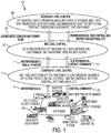
- a proposed high level control architecture 100 for the microgrid is shown in FIG. 1 .
- the control architecture comprises three layers.
- the first level or layer is a component control layer 110. That layer basically includes control devices that are directly attached to system DERs and loads in the physical microgrid assets 180. Examples of such control devices include the inverters in front of individual storage or photovoltaic resources, controllers for any traditional generators, load control devices, etc.
- a controller at the component control layer 110 is responsible for functions such as automatic generation control (AGC), frequency stability, voltage stability, load shedding, islanding detection, protection, fault current limiting controls, inverter control, compliance with IEEE standard 1547, droop controls, etc.
- a controller at the component control layer 110 is responsible for functions such as automatic generation control (AGC), frequency stability, voltage stability, load shedding, islanding detection, protection, fault current limiting controls, inverter control, compliance with IEEE standard 1547, droop controls, etc.
- a controller at the component control layer 110 is responsible for functions such as automatic generation control (AGC), frequency stability, voltage stability, load shedding, islanding detection, protection, fault current limiting controls, inverter control, compliance with IEEE standard 1547, droop controls, etc.
- the functionality of a controller at the component control layer 110 is directed only towards the equipment controlled by the controller.
- the control devices in the component control layer 110 receive instantaneous feedback data such as voltage and current measurements 111 from the physical microgrid assets 180, and
- the middle level control layer 130 comprises aggregating controllers that are responsible for aggregated DERs and loads within a geographical region.
- a controller is a device that is upstream of a community that includes several homes that have photovoltaic cells (PVs), a community battery storage, sectional switches (breakers) and loads (some of them controllable).
- PVs photovoltaic cells
- breakers sectional switches
- loads some of them controllable.
- Another example is a controller for a hospital that can control the hospital load, a battery storage, a backup generator, and a transfer switch.
- the aggregating controller can monitor instantaneous data 131 from the component level control layer 110 and can send control commands 132 (when required) to individual component control devices at the component level 110.
- An aggregating controller is responsible for functions such as optimization, Volt-var compensation, loss minimization, power management, etc.
- That functionality of the aggregating controllers is directed towards the downstream equipment controlled by the controller. Also, when required, an aggregating controller in the middle level control layer 130 is able to communicate with neighboring aggregating controllers. That communication is facilitated via a controller at the microgrid layer 150.
- the topmost layer is a microgrid control layer 150 that basically comprises a microgrid controller or a plurality of interconnected microgrid controllers. That controller is responsible for intentional islanding, DER and load dispatch, optimization, load scheduling, planning, market operation, ancillary services, storage management, grid synchronization, generation and load management, adaptive protection, contingency assessment, compliance with IEEE standard 1547, etc.
- the microgrid controller may monitor aggregated demands, power flow and other data 151 from the middle level control layer 130.
- the microgrid controller may send control command 152 (when required) to individual controllers at middle and component layer, including power dispatch, new control and protection settings, etc.
- the microgrid control layer 150 is also responsible for computation of a contingency metric, and performs generation, load, and weather forecasting.
- the microgrid control layer also computes predictions of near future system states. It monitors the whole system and decides the suitable control architecture for the system.
- the contingency or resiliency metric 280 is computed and monitored by the microgrid controller, using as inputs the characteristic shown in the diagram 200 of FIG. 2 .
- the contingency metric 280 is a function of predicted threat level or future system state 230, current system state 220, weather forecast 210, real time reserve margin 240 and communications from the utility grid 260.
- system here refers to the microgrid system.
- the contingency metric 280 gives a measure of threat to the microgrid in its ability to maintain a stable and survivable operation.
- the system state is classified into a contingency level.
- a contingency level In the present disclosure, four possible contingency levels are described. One skilled in the art will recognize that any number of contingency levels greater than 1 may be used.
- the architecture may use a binary classification system in which the microgrid is operating either with no operational threat or with an operational threat.
- three contingency levels may be used: normal operation, medium threat and high threat. Other arrangements having other numbers of contingency levels may be used.
- contingency level classes are assigned:
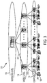
- FIGS. 3-6 show the changes in control architecture based on the determined contingency level.
- the green contingency level 300, resulting in the high level (logical) control architecture shown in FIG. 3 is a contingency level in which the threat is very low.
- the microgrid control architecture has following features:
- the lines 385 between the component layer 110 and the physical microgrid assets 180 are power lines and the remaining lines in the figure are communication lines.
- the lines 335, 355 represent strong control from top to bottom, which basically shows a tight, centralized control system.
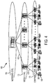
- the control architecture changes to an architecture 400 shown in FIG. 4 .
- the microgrid at that contingency level is mostly in an islanded mode of operation and utilizes microgrid resources to meet its operational needs.
- the microgrid control layer 150 has a reduced role in the monitoring and controlling of individual controllers at the middle layer 130 and component layer 110. Instead, the microgrid control layer 150 moves toward strictly monitoring and tracking the current and future system state. While the communications lines 435 between the middle layer 130 and the component layer 110 maintain close communications, the communication lines 455 between the microgrid layer 150 and the middle layer 130 see reduced traffic as because high level control is reduced. In that mode of operation the microgrid control architecture has following features:
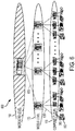
- the system may enter an orange contingency level, and require the control architecture to change to the architecture 500 shown in FIG. 5 .
- the microgrid control layer 150 cedes command to controllers in the lower layers 130, 110, and the microgrid control layer only monitors and records their activities, as shown by dotted communication lines 555.
- the middle control layer 130 takes responsibility in monitoring and controlling the microgrid physical assets 180 via controllers in the component layer 110 and communications lines 535.
- the microgrid system will keep functioning albeit with sub-optimal performance. That will lead to increased resiliency of the microgrid system.
- the microgrid system is divided into smaller microgrid sub-units, controlled by individual aggregating controllers in the middle layer 130 that can operate on their own. Also, when required, those microgrid sub-units in layer 130 may be able to contact a neighboring microgrid unit, via microgrid controller layer (via lines 555), for support. In that mode, the microgrid architecture will have following features:
- the control architecture 600 is completely de-centralized. Both the microgrid control layer 150 and the middle control layer 130 only monitor and record but do not send any command to a lower layer controller.
- the communication lines 655, 635 are therefore used only for monitoring and recording, and not for controlling.
- the controllers in the component layer 110 may be placed in a droop mode of control to keep the system voltage and frequency within prescribed limits. Automatic load shedding is implemented to keep the system serving at least the highest priority loads. In this mode the microgrid system performance will be quite suboptimal but the system will be highly resilient as it can withstand not only multiple communication failures but also multiple electrical faults.
- red contingency level, or the highest threat level the microgrid control architecture has following features:
- the microgrid controller at the microgrid level 150 will initiate the process of re-establishing an appropriate control architecture.
- the microgrid controller 150 is disabled or not able to communicate with middle level controllers 130 (due to severe communication failure of the lines 655), the system is manually operated until all the failures are cleared and communication is reestablished.
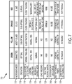
- the microgrid controller shown in line 705, is connected to the utility grid at the green contingency level, operates in mostly island mode at the yellow level, and operates in island mode at the orange and red levels.
- Overall operation of the microgrid, as shown in line 710, is optimal at the green contingency level, sub-optimal at the yellow and orange levels and operates for survival only at the red level.
- the weather and system state, shown in line 715 are tracked normally at the green contingency level and are tracked closely at all other levels.
- the overall control structure shown in line 720, changes from a centralized structure at the green and yellow contingency levels, to a partially decentralized structure at the orange level and a decentralized structure at the red level.
- the microgrid operates in a normal control mode at the green and yellow contingency levels, and changes to a monitoring-only mode at the orange level, as shown at line 725.
- both the microgrid controller and the mid-level controllers operate in a monitoring-only mode.
- Line 730 shows that load shedding is not required at the green and yellow levels (although it may be implemented for other reasons such as peak demand reduction).
- the microgrid controller performs a precomputation of load shedding control actions, and at the red level, load shedding is implemented according to those precomputed control actions.
- instructions and set points are transmitted by the microgrid controller layer to the middle layer and the component layer, as shown in line 745.
- the instructions and set points are transmitted by the middle layer controller.
- the component controllers operate in a droop control mode, without receiving instructions and set points from upstream.
- neighboring middle layer controllers may communicate with each other via the microgrid controller at the orange contingency level. Such communications takes place under normal operations at the green and yellow levels.
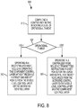
- a flow chart 800 illustrated in FIG. 8 , illustrates one method in accordance with the present disclosure.
- the method is for controlling an electrical power microgrid including loads and distributed energy resources.
- the method computes a contingency metric indicating a level of operational threat, based on characteristics of the electrical power microgrid and its environment.
- the contingency metric may be based on one or more of a predicted threat level or future system state, a current system state, a weather forecast, communications from the utility grid, and real time reserve margin.
- the computed contingency metric may be a value from 0 to 1, with a higher value indicating a greater risk or operational threat level. Based on the threat level, a decision 820 is made to operate under one of a plurality of modes. In the example 800 of FIG. 8 , two modes are used: a decentralized mode and a centralized mode. More operational modes, such as three or four modes, may be used. Each mode is assigned a range of the computed contingency metric.
- the system is operated at block 830 in a centralized mode.
- the centralized mode instructions and set points for the loads and distributed energy resources are transmitted from the microgrid control layer to the middle control layer and the component control layer.
- the system is operated at block 840 in a decentralized mode, including operating the component control layer without receiving instructions and set points from the middle level control layer or the microgrid control layer.
Landscapes
- Engineering & Computer Science (AREA)
- Power Engineering (AREA)
- Physics & Mathematics (AREA)
- General Physics & Mathematics (AREA)
- Automation & Control Theory (AREA)
- Electromagnetism (AREA)
- Radar, Positioning & Navigation (AREA)
- General Engineering & Computer Science (AREA)
- Supply And Distribution Of Alternating Current (AREA)
- Remote Monitoring And Control Of Power-Distribution Networks (AREA)
Claims (10)
- Steuersystem zum Steuern eines Mikronetzes für elektrische Energie, das Lasten und verteilte Energieressourcen enthält, das Steuersystem umfassend:eine Komponentensteuerschicht (110), die Komponentensteuerungsvorrichtungen enthält, die direkt mit den Lasten und verteilten Energieressourcen verbunden sind;eine Steuerschicht mittlerer Ebene (130), die aggregierte Steuerungsvorrichtungen enthält, wobei jede aggregierte Steuerungsvorrichtung mit einer jeweiligen Vielzahl der Komponentensteuerungsvorrichtungen verbunden ist;eine Mikronetzsteuerschicht (150), die eine oder mehrere Mikronetzsteuerungsvorrichtungen enthält, die mit den aggregierte Steuerungsvorrichtungen verbunden sind, und ferner ein Kontingenzmetrik-Berechnungsmodul zum Berechnen einer Kontingenzmetrik enthält, die eine Stufe einer operativen Bedrohung basierend auf Eigenschaften des Mikronetzes für elektrische Energie und seiner Umgebung angibt;
wobeiin einer ersten Kontingenzstufe (300), die im Wesentlichen keine operative Bedrohung angibt, sich das Mikronetz in einem netzgekoppelten Modus befindet, das Steuersystem einen hohen Echtzeit-Reservespielraum aufrechterhält und das Steuersystem konfiguriert ist, um in einem zentralisierten Modus betrieben zu werden, wobei Anweisungen und Sollwerte für die Lasten und verteilten Energieressourcen von der Mikronetzsteuerschicht an die Steuerschicht mittlerer Ebene und die Komponentensteuerschicht übertragen werden;in einer zweiten Kontingenzstufe (400), die eine mittlere operative Bedrohung angibt, sich das Mikronetz zumeist im Inselmodus befindet, das Steuersystem einen niedrigen Echtzeit-Reservespielraum aufrechterhält und das Steuersystem konfiguriert ist, um in einem teilweise zentralisierten Modus betrieben zu werden, wobei mindestens einige Anweisungen und Sollwerte für die Lasten und verteilten Energieressourcen von den aggregierten Steuerungsvorrichtungen stammen und wobei sich die Mikronetzsteuerschicht in Richtung einer strengen Überwachung und Verfolgung des aktuellen und zukünftigen Systemzustands bewegt;in einer dritten Kontingenzstufe (500), die eine hohe operative Bedrohung angibt, sich das Mikronetz im Inselmodus befindet, das Steuersystem einen minimalen Echtzeit-Reservespielraum aufrechterhält, das Steuersystem konfiguriert ist, um in einem teilweise zentralisierten Modus betrieben zu werden, wobei Anweisungen und Sollwerte für die Lasten und verteilten Energieressourcen von den aggregierten Steuerungsvorrichtungen stammen, die Mikronetzsteuerung sich in einem Nur-Überwachungsmodus befindet und Vorberechnungen der Steueraktionen für den Lastabwurf durchführt, benachbarte Steuerungen der mittleren Ebene bei Bedarf über die Mikronetzsteuerung miteinander kommunizieren und, soweit möglich, ein Systemsicherungsspeicher verwendet wird;in einer vierten Kontingenzstufe (600), die eine sehr hohe operative Bedrohung angibt, sich das Mikronetz im Inselmodus befindet, das Steuersystem keinen Echtzeit-Reservespielraum aufrechterhält, das Steuersystem konfiguriert ist, um in einem dezentralisierten Modus betrieben zu werden, wobei die Komponentensteuerschicht betrieben wird, ohne Anweisungen und Sollwerte von der Steuerschicht mittlerer Ebene oder der Mikronetzsteuerschicht zu empfangen, sich die Mikronetzsteuerung und die Steuerungen mittlerer Ebene im Nur-Überwachungsmodus befinden, die Komponentensteuerungsvorrichtungen in der Komponentensteuerschicht in den Absenkungsmodus versetzt werden, die automatische Lastabschaltung implementiert wird, um mindestens die Lasten mit höchster Priorität zu bedienen, und alle Reserven und Speicher verwendet werden. - Steuersystem nach Anspruch 1, wobei der Betrieb in einem dezentralisierten Modus ferner beinhaltet:
Verfolgung von Wetter- und Systemzustand zur Verwendung durch das Kontingenzmetrik-Berechnungsmodul. - Steuersystem nach Anspruch 1, wobei die Eigenschaften des Mikronetzes für elektrische Energie und seiner Umgebung, auf der die Kontingenzmetrik basiert, eine Wettervorhersage oder Kommunikationen von einem Versorgungsnetz enthalten.
- Steuersystem nach Anspruch 1, wobei die Eigenschaften des Mikronetzes für elektrische Energie und seiner Umgebung, auf der die Kontingenzmetrik basiert, jeweils die folgenden Eigenschaften enthalten: einen aktuellen Zustand, einen vorhergesagten Zustand und eine Reservestufe.
- Steuersystem nach Anspruch 1, wobei der dezentrale Modus die Durchführung von Überwachungsfunktionen ohne Aufsichtsfunktionen durch die Mikronetzsteuerschicht und die Steuerschicht mittlerer Ebene beinhaltet.
- Verfahren zum Steuern eines Mikronetzes für elektrische Energie, das Lasten und verteilte Energieressourcen enthält, wobei das Energie-Mikronetz ein Steuersystem enthält, das eine Komponentensteuerschicht, die Komponentensteuerungsvorrichtungen enthält, die direkt mit den Lasten und verteilten Energieressourcen verbunden sind, eine Steuerschicht mittlerer Ebene, die aggregierte Steuerungsvorrichtungen enthält, wobei jede aggregierte Steuerungsvorrichtung mit einer jeweiligen Vielzahl der Komponentensteuerungsvorrichtungen verbunden ist, und eine Mikronetzsteuerschicht, die eine oder mehrere Mikronetzsteuerungsvorrichtungen enthält, die mit den aggregierte Steuerungsvorrichtungen verbunden sind, umfasst, wobei das Verfahren umfasst:Berechnen einer Kontingenzmetrik, die eine Stufe einer operativen Bedrohung basierend auf Eigenschaften des Mikronetzes für elektrische Energie und seiner Umgebung angibt;Betreiben des Mikronetzes für elektrische Energie gemäß der berechneten Kontingenzstufe, wobeiin einer ersten Kontingenzstufe (300), die im Wesentlichen keine operative Bedrohung angibt, sich das Mikronetz in einem netzgekoppelten Modus befindet, das Steuersystem einen hohen Echtzeit-Reservespielraum aufrechterhält und das Steuersystem konfiguriert ist, um in einem zentralisierten Modus betrieben zu werden, wobei Anweisungen und Sollwerte für die Lasten und verteilten Energieressourcen von der Mikronetzsteuerschicht an die Steuerschicht mittlerer Ebene und die Komponentensteuerschicht übertragen werden;in einer zweiten Kontingenzstufe (400), die eine mittlere operative Bedrohung angibt, sich das Mikronetz zumeist im Inselmodus befindet, das Steuersystem einen niedrigen Echtzeit-Reservespielraum aufrechterhält und das Steuersystem konfiguriert ist, um in einem teilweise zentralisierten Modus betrieben zu werden, in dem mindestens einige Anweisungen und Sollwerte für die Lasten und verteilten Energieressourcen von den aggregierten Steuerungsvorrichtungen stammen und wobei sich die Mikronetzsteuerschicht in Richtung einer strengen Überwachung und Verfolgung des aktuellen und zukünftigen Systemzustands bewegt;in einer dritten Kontingenzstufe (500), die eine hohe operative Bedrohung angibt, sich das Mikronetz im Inselmodus befindet, das Steuersystem einen minimalen Echtzeit-Reservespielraum aufrechterhält, das Steuersystem konfiguriert ist, um in einem teilweise zentralisierten Modus betrieben zu werden, wobei Anweisungen und Sollwerte für die Lasten und verteilten Energieressourcen von den aggregierte Steuerungsvorrichtungen stammen, die Mikronetzsteuerung sich in einem Nur-Überwachungsmodus befindet und Vorberechnungen der Steueraktionen für den Lastabwurf durchführt, benachbarte Steuerungen der mittleren Ebene bei Bedarf über die Mikronetzsteuerung miteinander kommunizieren und, soweit möglich, ein Systemsicherungsspeicher verwendet wird;in einer vierten Kontingenzstufe (600), die eine sehr hohe operative Bedrohung angibt, sich das Mikronetz im Inselmodus befindet, das Steuersystem keinen Echtzeit-Reservespielraum aufrechterhält, das Steuersystem konfiguriert ist, um in einem dezentralisierten Modus betrieben zu werden, wobei die Komponentensteuerschicht betrieben wird, ohne Anweisungen und Sollwerte von der Steuerschicht mittlerer Ebene oder der Mikronetzsteuerschicht zu empfangen, sich die Mikronetzsteuerung und die Steuerungen mittlerer Ebene im Nur-Überwachungsmodus befinden, die Komponentensteuerungsvorrichtungen in der Komponentensteuerschicht in den Absenkungsmodus versetzt werden, die automatische Lastabschaltung implementiert wird, um mindestens die Lasten mit höchster Priorität zu bedienen, und alle Reserven und Speicher verwendet werden.
- Verfahren nach Anspruch 6, wobei der Betrieb in dem dezentralisierten Modus das Verfolgen eines Wetterzustands und eines Systemzustands zur Verwendung durch das Kontingenzmetrik-Berechnungsmodul beinhaltet.
- Verfahren nach Anspruch 6, wobei die Eigenschaften des Mikronetzes für elektrische Energie und seiner Umgebung, auf der die Kontingenzmetrik basiert, eine Wettervorhersage oder Kommunikationen von einem Versorgungsnetz enthalten.
- Verfahren nach Anspruch 6, wobei die Eigenschaften des Mikronetzes für elektrische Energie und seiner Umgebung, auf der die Kontingenzmetrik basiert, jeweils die folgenden Eigenschaften enthalten: einen aktuellen Zustand, einen vorhergesagten Zustand und eine Reservestufe.
- Verfahren nach Anspruch 6, wobei der Betrieb in dem dezentralisierten Modus ferner beinhaltet:
Durchführen, durch die Mikronetzsteuerschicht und die Steuerschicht mittlerer Ebene, von Überwachungsfunktionen ohne Aufsichtsfunktionen.
Applications Claiming Priority (2)
| Application Number | Priority Date | Filing Date | Title |
|---|---|---|---|
| US201461982593P | 2014-04-22 | 2014-04-22 | |
| PCT/US2015/026740 WO2015164292A1 (en) | 2014-04-22 | 2015-04-21 | Flexible control architecture for microgrid resiliency |
Publications (2)
| Publication Number | Publication Date |
|---|---|
| EP3134950A1 EP3134950A1 (de) | 2017-03-01 |
| EP3134950B1 true EP3134950B1 (de) | 2019-04-03 |
Family
ID=53200289
Family Applications (1)
| Application Number | Title | Priority Date | Filing Date |
|---|---|---|---|
| EP15724113.4A Not-in-force EP3134950B1 (de) | 2014-04-22 | 2015-04-21 | Flexible steuerungsarchitektur für mikronetzelastizität |
Country Status (4)
| Country | Link |
|---|---|
| US (1) | US10116164B2 (de) |
| EP (1) | EP3134950B1 (de) |
| PT (1) | PT3134950T (de) |
| WO (1) | WO2015164292A1 (de) |
Families Citing this family (18)
| Publication number | Priority date | Publication date | Assignee | Title |
|---|---|---|---|---|
| US10585445B2 (en) * | 2015-02-02 | 2020-03-10 | Opus One Solutions Energy Corporation | Systems and methods for volt/VAR control in electric power management and automation systems |
| US10423185B2 (en) | 2016-05-09 | 2019-09-24 | General Electric Company | Systems and methods for regulating a microgrid |
| US10516269B2 (en) | 2016-11-16 | 2019-12-24 | Alliance For Sustainable Energy, Llc | Real time feedback-based optimization of distributed energy resources |
| IT201600131878A1 (it) * | 2016-12-28 | 2018-06-28 | Electro Power Systems Mfg S R L | Sistema di controllo di microreti di produzione e distribuzione di energia elettrica proveniente da più fonti di produzione di tipo diverso, e relativo metodo di controllo |
| US9997956B1 (en) | 2017-02-23 | 2018-06-12 | Siemens Industry, Inc. | Systems, apparatus, and methods for automatic generation control islanded operation |
| US11003146B2 (en) * | 2017-03-17 | 2021-05-11 | General Electric Company | Distributed optimal control of an aircraft propulsion system |
| CN111373423A (zh) * | 2017-07-18 | 2020-07-03 | 西门子公司 | 多代理流量控制系统的分散式计划、调度与控制 |
| US10613492B2 (en) | 2017-07-26 | 2020-04-07 | General Electric Company | Method and system for providing flexible reserve power for power grid |
| CN111433996A (zh) * | 2017-11-28 | 2020-07-17 | Ls电气株式会社 | 分级电力控制系统 |
| US20200021131A1 (en) * | 2018-07-16 | 2020-01-16 | Battelle Memorial Institute | Control for energy resources in a microgrid |
| US12331721B2 (en) | 2018-07-31 | 2025-06-17 | Alliance For Sustainable Energy, Llc | Distributed reinforcement learning and consensus control of energy systems |
| US11725625B2 (en) | 2018-07-31 | 2023-08-15 | Alliance For Sustainable Energy, Llc | Distributed reinforcement learning and consensus control of energy systems |
| EP3627433B1 (de) | 2018-09-19 | 2021-11-24 | Hitachi Energy Switzerland AG | Resilienzbestimmung in einem mikronetz |
| US11133679B2 (en) * | 2019-02-27 | 2021-09-28 | General Electric Company | System and method for operating a hybrid energy facility having multiple power sources |
| CN110535144A (zh) * | 2019-09-27 | 2019-12-03 | 国网甘肃省电力公司经济技术研究院 | 风沙天气下含多类型负荷的智能配电网韧性定量分析方法 |
| MA50325B1 (fr) | 2020-08-03 | 2022-04-29 | Univ Ibn Tofail | Une méthode de contrôle des onduleurs de source de tension pour la flexibilité des microréseaux électriques à courant alternatif |
| CN114530841B (zh) * | 2021-12-03 | 2025-06-27 | 国网浙江省电力有限公司嘉兴供电公司 | 一种配电网紧急状态下的全局协调控制架构优化方法 |
| EP4589800A1 (de) * | 2024-01-17 | 2025-07-23 | Hitachi Energy Ltd | Berechnung präventiv eingestufter elastizitätsmessungen mit probabilistischer optimierung für verbesserte betriebssicherheit eines stromversorgungssystems |
Family Cites Families (11)
| Publication number | Priority date | Publication date | Assignee | Title |
|---|---|---|---|---|
| SE517963C2 (sv) | 2000-05-31 | 2002-08-06 | Abb Ab | Nätvärnssystem för skydd av ett totalt elkraftsystems integritet, elkraftsystem innefattande ett nätvärn, systemskyddsförfarande, systemskyddsterminal samt datorprogramprodukt |
| US9148019B2 (en) * | 2010-12-06 | 2015-09-29 | Sandia Corporation | Computing architecture for autonomous microgrids |
| US20110087384A1 (en) * | 2009-10-09 | 2011-04-14 | Consolidated Edison Company Of New York, Inc. | System and method for conserving electrical capacity |
| US20120229081A1 (en) * | 2009-11-30 | 2012-09-13 | Kyocera Corporation | Control device and control method |
| WO2012015508A1 (en) | 2010-07-29 | 2012-02-02 | Spirae, Inc. | Dynamic distributed power grid control system |
| US8766474B2 (en) * | 2011-01-12 | 2014-07-01 | The Boeing Company | Smart microgrid reconfigurable AC interface |
| US9026260B1 (en) * | 2011-05-23 | 2015-05-05 | Shaw Intellectual Property Holdings, Inc. | Secure microgrid |
| EP2600479A1 (de) * | 2011-12-02 | 2013-06-05 | ABB Research Ltd. | Steuerung eines Stromnetzes mit inselartigem Betrieb |
| US9244446B2 (en) * | 2012-11-29 | 2016-01-26 | International Business Machines Corporation | Configuring, optimizing and managing micro-grids |
| US9454137B2 (en) * | 2013-03-01 | 2016-09-27 | Honeywell International Inc. | System and method of large area microgrid stability controls |
| US9733623B2 (en) * | 2013-07-31 | 2017-08-15 | Abb Research Ltd. | Microgrid energy management system and method for controlling operation of a microgrid |
-
2015
- 2015-04-21 EP EP15724113.4A patent/EP3134950B1/de not_active Not-in-force
- 2015-04-21 PT PT15724113T patent/PT3134950T/pt unknown
- 2015-04-21 WO PCT/US2015/026740 patent/WO2015164292A1/en not_active Ceased
- 2015-04-21 US US15/303,914 patent/US10116164B2/en active Active
Non-Patent Citations (1)
| Title |
|---|
| None * |
Also Published As
| Publication number | Publication date |
|---|---|
| PT3134950T (pt) | 2019-06-27 |
| EP3134950A1 (de) | 2017-03-01 |
| US10116164B2 (en) | 2018-10-30 |
| US20170040839A1 (en) | 2017-02-09 |
| WO2015164292A1 (en) | 2015-10-29 |
Similar Documents
| Publication | Publication Date | Title |
|---|---|---|
| EP3134950B1 (de) | Flexible steuerungsarchitektur für mikronetzelastizität | |
| US12224583B2 (en) | Highly flexible, electrical distribution grid edge energy manager and router | |
| US11652365B2 (en) | Highly flexible electrical distribution grid edge energy manager and router | |
| US10923913B2 (en) | Method for operating an electrical energy supply network, and control device for controlling devices of an electrical distribution network | |
| CN104541294B (zh) | 用于取决于供电系统中的状况来对电信网络的电能消耗进行时空控制的方法和设备 | |
| EP3133715B1 (de) | Ressourcenverwaltungssystem | |
| US20220231538A1 (en) | Power distribution systems and methods | |
| US12424849B2 (en) | Method of controlling a power distribution system including a microgrid | |
| JP2019161706A (ja) | 電力融通システム | |
| Li et al. | Role of microgrids in enhancing power system resilience | |
| JP6356517B2 (ja) | 系統監視制御装置 | |
| Fard et al. | Holistic multi-timescale attack resilient control framework for power electronics dominated grid | |
| Eissa et al. | Emergency frequency control by using heavy thermal conditioning loads in commercial buildings at smart grids | |
| EP3937344B1 (de) | Verfahren zum betrieb einer intelligenten elektronischen vorrichtung und intelligente elektronische vorrichtung | |
| CN117691571B (zh) | 一种低压台区柔性互联技术控制方法及系统 | |
| Kumar et al. | Reliability aspects in the design and development of microgrids | |
| CA3164108C (en) | Power distribution systems and methods | |
| Shaaban et al. | Operational security criterion of a smart grid | |
| Amleh et al. | Smart restoration for improved reliability of microgrids with renewable energy sources | |
| Ilić et al. | AC-extended optimal power flow (AC XOPF) for reliable grid operations and planning in support of energy transition: Puerto Rico power grid case | |
| De Meer et al. | On the Resilience of Mutually Dependent Power and Data Networks | |
| Uriarte et al. | Intelligent Microgrids | |
| Saleh et al. | How does access to this work benefit you? Let us know! | |
| KR20180060815A (ko) | 전원 제어 장치 |
Legal Events
| Date | Code | Title | Description |
|---|---|---|---|
| STAA | Information on the status of an ep patent application or granted ep patent |
Free format text: STATUS: THE INTERNATIONAL PUBLICATION HAS BEEN MADE |
|
| PUAI | Public reference made under article 153(3) epc to a published international application that has entered the european phase |
Free format text: ORIGINAL CODE: 0009012 |
|
| STAA | Information on the status of an ep patent application or granted ep patent |
Free format text: STATUS: REQUEST FOR EXAMINATION WAS MADE |
|
| 17P | Request for examination filed |
Effective date: 20160928 |
|
| AK | Designated contracting states |
Kind code of ref document: A1 Designated state(s): AL AT BE BG CH CY CZ DE DK EE ES FI FR GB GR HR HU IE IS IT LI LT LU LV MC MK MT NL NO PL PT RO RS SE SI SK SM TR |
|
| AX | Request for extension of the european patent |
Extension state: BA ME |
|
| DAV | Request for validation of the european patent (deleted) | ||
| DAX | Request for extension of the european patent (deleted) | ||
| RAP1 | Party data changed (applicant data changed or rights of an application transferred) |
Owner name: SIEMENS AKTIENGESELLSCHAFT |
|
| GRAP | Despatch of communication of intention to grant a patent |
Free format text: ORIGINAL CODE: EPIDOSNIGR1 |
|
| STAA | Information on the status of an ep patent application or granted ep patent |
Free format text: STATUS: GRANT OF PATENT IS INTENDED |
|
| INTG | Intention to grant announced |
Effective date: 20181119 |
|
| GRAS | Grant fee paid |
Free format text: ORIGINAL CODE: EPIDOSNIGR3 |
|
| GRAA | (expected) grant |
Free format text: ORIGINAL CODE: 0009210 |
|
| STAA | Information on the status of an ep patent application or granted ep patent |
Free format text: STATUS: THE PATENT HAS BEEN GRANTED |
|
| AK | Designated contracting states |
Kind code of ref document: B1 Designated state(s): AL AT BE BG CH CY CZ DE DK EE ES FI FR GB GR HR HU IE IS IT LI LT LU LV MC MK MT NL NO PL PT RO RS SE SI SK SM TR |
|
| REG | Reference to a national code |
Ref country code: GB Ref legal event code: FG4D |
|
| REG | Reference to a national code |
Ref country code: CH Ref legal event code: EP Ref country code: AT Ref legal event code: REF Ref document number: 1116934 Country of ref document: AT Kind code of ref document: T Effective date: 20190415 |
|
| REG | Reference to a national code |
Ref country code: DE Ref legal event code: R096 Ref document number: 602015027559 Country of ref document: DE |
|
| REG | Reference to a national code |
Ref country code: IE Ref legal event code: FG4D |
|
| REG | Reference to a national code |
Ref country code: PT Ref legal event code: SC4A Ref document number: 3134950 Country of ref document: PT Date of ref document: 20190627 Kind code of ref document: T Free format text: AVAILABILITY OF NATIONAL TRANSLATION Effective date: 20190617 |
|
| REG | Reference to a national code |
Ref country code: NL Ref legal event code: MP Effective date: 20190403 |
|
| REG | Reference to a national code |
Ref country code: LT Ref legal event code: MG4D |
|
| REG | Reference to a national code |
Ref country code: AT Ref legal event code: MK05 Ref document number: 1116934 Country of ref document: AT Kind code of ref document: T Effective date: 20190403 |
|
| PG25 | Lapsed in a contracting state [announced via postgrant information from national office to epo] |
Ref country code: NL Free format text: LAPSE BECAUSE OF FAILURE TO SUBMIT A TRANSLATION OF THE DESCRIPTION OR TO PAY THE FEE WITHIN THE PRESCRIBED TIME-LIMIT Effective date: 20190403 |
|
| PG25 | Lapsed in a contracting state [announced via postgrant information from national office to epo] |
Ref country code: LT Free format text: LAPSE BECAUSE OF FAILURE TO SUBMIT A TRANSLATION OF THE DESCRIPTION OR TO PAY THE FEE WITHIN THE PRESCRIBED TIME-LIMIT Effective date: 20190403 Ref country code: SE Free format text: LAPSE BECAUSE OF FAILURE TO SUBMIT A TRANSLATION OF THE DESCRIPTION OR TO PAY THE FEE WITHIN THE PRESCRIBED TIME-LIMIT Effective date: 20190403 Ref country code: NO Free format text: LAPSE BECAUSE OF FAILURE TO SUBMIT A TRANSLATION OF THE DESCRIPTION OR TO PAY THE FEE WITHIN THE PRESCRIBED TIME-LIMIT Effective date: 20190703 Ref country code: ES Free format text: LAPSE BECAUSE OF FAILURE TO SUBMIT A TRANSLATION OF THE DESCRIPTION OR TO PAY THE FEE WITHIN THE PRESCRIBED TIME-LIMIT Effective date: 20190403 Ref country code: HR Free format text: LAPSE BECAUSE OF FAILURE TO SUBMIT A TRANSLATION OF THE DESCRIPTION OR TO PAY THE FEE WITHIN THE PRESCRIBED TIME-LIMIT Effective date: 20190403 Ref country code: CZ Free format text: LAPSE BECAUSE OF FAILURE TO SUBMIT A TRANSLATION OF THE DESCRIPTION OR TO PAY THE FEE WITHIN THE PRESCRIBED TIME-LIMIT Effective date: 20190403 Ref country code: AL Free format text: LAPSE BECAUSE OF FAILURE TO SUBMIT A TRANSLATION OF THE DESCRIPTION OR TO PAY THE FEE WITHIN THE PRESCRIBED TIME-LIMIT Effective date: 20190403 |
|
| PG25 | Lapsed in a contracting state [announced via postgrant information from national office to epo] |
Ref country code: GR Free format text: LAPSE BECAUSE OF FAILURE TO SUBMIT A TRANSLATION OF THE DESCRIPTION OR TO PAY THE FEE WITHIN THE PRESCRIBED TIME-LIMIT Effective date: 20190704 Ref country code: BG Free format text: LAPSE BECAUSE OF FAILURE TO SUBMIT A TRANSLATION OF THE DESCRIPTION OR TO PAY THE FEE WITHIN THE PRESCRIBED TIME-LIMIT Effective date: 20190703 Ref country code: PL Free format text: LAPSE BECAUSE OF FAILURE TO SUBMIT A TRANSLATION OF THE DESCRIPTION OR TO PAY THE FEE WITHIN THE PRESCRIBED TIME-LIMIT Effective date: 20190403 Ref country code: RS Free format text: LAPSE BECAUSE OF FAILURE TO SUBMIT A TRANSLATION OF THE DESCRIPTION OR TO PAY THE FEE WITHIN THE PRESCRIBED TIME-LIMIT Effective date: 20190403 Ref country code: LV Free format text: LAPSE BECAUSE OF FAILURE TO SUBMIT A TRANSLATION OF THE DESCRIPTION OR TO PAY THE FEE WITHIN THE PRESCRIBED TIME-LIMIT Effective date: 20190403 |
|
| REG | Reference to a national code |
Ref country code: CH Ref legal event code: PL |
|
| REG | Reference to a national code |
Ref country code: BE Ref legal event code: MM Effective date: 20190430 |
|
| PG25 | Lapsed in a contracting state [announced via postgrant information from national office to epo] |
Ref country code: LU Free format text: LAPSE BECAUSE OF NON-PAYMENT OF DUE FEES Effective date: 20190421 Ref country code: IS Free format text: LAPSE BECAUSE OF FAILURE TO SUBMIT A TRANSLATION OF THE DESCRIPTION OR TO PAY THE FEE WITHIN THE PRESCRIBED TIME-LIMIT Effective date: 20190803 Ref country code: AT Free format text: LAPSE BECAUSE OF FAILURE TO SUBMIT A TRANSLATION OF THE DESCRIPTION OR TO PAY THE FEE WITHIN THE PRESCRIBED TIME-LIMIT Effective date: 20190403 |
|
| REG | Reference to a national code |
Ref country code: DE Ref legal event code: R097 Ref document number: 602015027559 Country of ref document: DE |
|
| PG25 | Lapsed in a contracting state [announced via postgrant information from national office to epo] |
Ref country code: EE Free format text: LAPSE BECAUSE OF FAILURE TO SUBMIT A TRANSLATION OF THE DESCRIPTION OR TO PAY THE FEE WITHIN THE PRESCRIBED TIME-LIMIT Effective date: 20190403 Ref country code: DK Free format text: LAPSE BECAUSE OF FAILURE TO SUBMIT A TRANSLATION OF THE DESCRIPTION OR TO PAY THE FEE WITHIN THE PRESCRIBED TIME-LIMIT Effective date: 20190403 Ref country code: SK Free format text: LAPSE BECAUSE OF FAILURE TO SUBMIT A TRANSLATION OF THE DESCRIPTION OR TO PAY THE FEE WITHIN THE PRESCRIBED TIME-LIMIT Effective date: 20190403 Ref country code: MC Free format text: LAPSE BECAUSE OF FAILURE TO SUBMIT A TRANSLATION OF THE DESCRIPTION OR TO PAY THE FEE WITHIN THE PRESCRIBED TIME-LIMIT Effective date: 20190403 Ref country code: CH Free format text: LAPSE BECAUSE OF NON-PAYMENT OF DUE FEES Effective date: 20190430 Ref country code: LI Free format text: LAPSE BECAUSE OF NON-PAYMENT OF DUE FEES Effective date: 20190430 Ref country code: RO Free format text: LAPSE BECAUSE OF FAILURE TO SUBMIT A TRANSLATION OF THE DESCRIPTION OR TO PAY THE FEE WITHIN THE PRESCRIBED TIME-LIMIT Effective date: 20190403 |
|
| PLBE | No opposition filed within time limit |
Free format text: ORIGINAL CODE: 0009261 |
|
| STAA | Information on the status of an ep patent application or granted ep patent |
Free format text: STATUS: NO OPPOSITION FILED WITHIN TIME LIMIT |
|
| PG25 | Lapsed in a contracting state [announced via postgrant information from national office to epo] |
Ref country code: BE Free format text: LAPSE BECAUSE OF NON-PAYMENT OF DUE FEES Effective date: 20190430 Ref country code: SM Free format text: LAPSE BECAUSE OF FAILURE TO SUBMIT A TRANSLATION OF THE DESCRIPTION OR TO PAY THE FEE WITHIN THE PRESCRIBED TIME-LIMIT Effective date: 20190403 Ref country code: IT Free format text: LAPSE BECAUSE OF FAILURE TO SUBMIT A TRANSLATION OF THE DESCRIPTION OR TO PAY THE FEE WITHIN THE PRESCRIBED TIME-LIMIT Effective date: 20190403 |
|
| 26N | No opposition filed |
Effective date: 20200106 |
|
| PG25 | Lapsed in a contracting state [announced via postgrant information from national office to epo] |
Ref country code: TR Free format text: LAPSE BECAUSE OF FAILURE TO SUBMIT A TRANSLATION OF THE DESCRIPTION OR TO PAY THE FEE WITHIN THE PRESCRIBED TIME-LIMIT Effective date: 20190403 |
|
| PG25 | Lapsed in a contracting state [announced via postgrant information from national office to epo] |
Ref country code: IE Free format text: LAPSE BECAUSE OF NON-PAYMENT OF DUE FEES Effective date: 20190421 |
|
| PG25 | Lapsed in a contracting state [announced via postgrant information from national office to epo] |
Ref country code: SI Free format text: LAPSE BECAUSE OF FAILURE TO SUBMIT A TRANSLATION OF THE DESCRIPTION OR TO PAY THE FEE WITHIN THE PRESCRIBED TIME-LIMIT Effective date: 20190403 |
|
| PG25 | Lapsed in a contracting state [announced via postgrant information from national office to epo] |
Ref country code: FR Free format text: LAPSE BECAUSE OF NON-PAYMENT OF DUE FEES Effective date: 20190603 |
|
| PG25 | Lapsed in a contracting state [announced via postgrant information from national office to epo] |
Ref country code: CY Free format text: LAPSE BECAUSE OF FAILURE TO SUBMIT A TRANSLATION OF THE DESCRIPTION OR TO PAY THE FEE WITHIN THE PRESCRIBED TIME-LIMIT Effective date: 20190403 |
|
| PG25 | Lapsed in a contracting state [announced via postgrant information from national office to epo] |
Ref country code: MT Free format text: LAPSE BECAUSE OF FAILURE TO SUBMIT A TRANSLATION OF THE DESCRIPTION OR TO PAY THE FEE WITHIN THE PRESCRIBED TIME-LIMIT Effective date: 20190403 Ref country code: HU Free format text: LAPSE BECAUSE OF FAILURE TO SUBMIT A TRANSLATION OF THE DESCRIPTION OR TO PAY THE FEE WITHIN THE PRESCRIBED TIME-LIMIT; INVALID AB INITIO Effective date: 20150421 |
|
| PG25 | Lapsed in a contracting state [announced via postgrant information from national office to epo] |
Ref country code: MK Free format text: LAPSE BECAUSE OF FAILURE TO SUBMIT A TRANSLATION OF THE DESCRIPTION OR TO PAY THE FEE WITHIN THE PRESCRIBED TIME-LIMIT Effective date: 20190403 |
|
| PGFP | Annual fee paid to national office [announced via postgrant information from national office to epo] |
Ref country code: DE Payment date: 20220620 Year of fee payment: 9 |
|
| PGFP | Annual fee paid to national office [announced via postgrant information from national office to epo] |
Ref country code: GB Payment date: 20230504 Year of fee payment: 9 |
|
| PGFP | Annual fee paid to national office [announced via postgrant information from national office to epo] |
Ref country code: PT Payment date: 20240324 Year of fee payment: 10 |
|
| PGFP | Annual fee paid to national office [announced via postgrant information from national office to epo] |
Ref country code: FI Payment date: 20240425 Year of fee payment: 10 |
|
| REG | Reference to a national code |
Ref country code: DE Ref legal event code: R119 Ref document number: 602015027559 Country of ref document: DE |
|
| GBPC | Gb: european patent ceased through non-payment of renewal fee |
Effective date: 20240421 |
|
| PG25 | Lapsed in a contracting state [announced via postgrant information from national office to epo] |
Ref country code: DE Free format text: LAPSE BECAUSE OF NON-PAYMENT OF DUE FEES Effective date: 20241105 |
|
| PG25 | Lapsed in a contracting state [announced via postgrant information from national office to epo] |
Ref country code: GB Free format text: LAPSE BECAUSE OF NON-PAYMENT OF DUE FEES Effective date: 20240421 |
|
| PG25 | Lapsed in a contracting state [announced via postgrant information from national office to epo] |
Ref country code: GB Free format text: LAPSE BECAUSE OF NON-PAYMENT OF DUE FEES Effective date: 20240421 Ref country code: DE Free format text: LAPSE BECAUSE OF NON-PAYMENT OF DUE FEES Effective date: 20241105 |
|
| PG25 | Lapsed in a contracting state [announced via postgrant information from national office to epo] |
Ref country code: PT Free format text: LAPSE BECAUSE OF NON-PAYMENT OF DUE FEES Effective date: 20251021 |
|
| PG25 | Lapsed in a contracting state [announced via postgrant information from national office to epo] |
Ref country code: FI Free format text: LAPSE BECAUSE OF NON-PAYMENT OF DUE FEES Effective date: 20250421 |