EP3027552B1 - Herstellung von syngas durch co2-reduktionsverfahren - Google Patents
Herstellung von syngas durch co2-reduktionsverfahren Download PDFInfo
- Publication number
- EP3027552B1 EP3027552B1 EP14777817.9A EP14777817A EP3027552B1 EP 3027552 B1 EP3027552 B1 EP 3027552B1 EP 14777817 A EP14777817 A EP 14777817A EP 3027552 B1 EP3027552 B1 EP 3027552B1
- Authority
- EP
- European Patent Office
- Prior art keywords
- reactor
- process according
- sep
- leaving
- sulfur
- Prior art date
- Legal status (The legal status is an assumption and is not a legal conclusion. Google has not performed a legal analysis and makes no representation as to the accuracy of the status listed.)
- Active
Links
Images

Classifications
-
- C—CHEMISTRY; METALLURGY
- C01—INORGANIC CHEMISTRY
- C01B—NON-METALLIC ELEMENTS; COMPOUNDS THEREOF; METALLOIDS OR COMPOUNDS THEREOF NOT COVERED BY SUBCLASS C01C
- C01B3/00—Hydrogen; Gaseous mixtures containing hydrogen; Separation of hydrogen from mixtures containing it; Purification of hydrogen; Reversible storage of hydrogen
- C01B3/02—Production of hydrogen; Production of gaseous mixtures containing hydrogen
- C01B3/06—Production of hydrogen; Production of gaseous mixtures containing hydrogen by reaction of inorganic compounds containing electro-positively bound hydrogen with inorganic reducing agents
-
- C—CHEMISTRY; METALLURGY
- C01—INORGANIC CHEMISTRY
- C01B—NON-METALLIC ELEMENTS; COMPOUNDS THEREOF; METALLOIDS OR COMPOUNDS THEREOF NOT COVERED BY SUBCLASS C01C
- C01B17/00—Sulfur; Compounds thereof
- C01B17/02—Preparation of sulfur; Purification
- C01B17/04—Preparation of sulfur; Purification from gaseous sulfur compounds including gaseous sulfides
- C01B17/0404—Preparation of sulfur; Purification from gaseous sulfur compounds including gaseous sulfides by processes comprising a dry catalytic conversion of hydrogen sulfide-containing gases, e.g. the Claus process
- C01B17/0408—Pretreatment of the hydrogen sulfide containing gases
-
- C—CHEMISTRY; METALLURGY
- C01—INORGANIC CHEMISTRY
- C01B—NON-METALLIC ELEMENTS; COMPOUNDS THEREOF; METALLOIDS OR COMPOUNDS THEREOF NOT COVERED BY SUBCLASS C01C
- C01B17/00—Sulfur; Compounds thereof
- C01B17/48—Sulfur dioxide; Sulfurous acid
- C01B17/50—Preparation of sulfur dioxide
- C01B17/508—Preparation of sulfur dioxide by oxidation of sulfur compounds
-
- Y—GENERAL TAGGING OF NEW TECHNOLOGICAL DEVELOPMENTS; GENERAL TAGGING OF CROSS-SECTIONAL TECHNOLOGIES SPANNING OVER SEVERAL SECTIONS OF THE IPC; TECHNICAL SUBJECTS COVERED BY FORMER USPC CROSS-REFERENCE ART COLLECTIONS [XRACs] AND DIGESTS
- Y02—TECHNOLOGIES OR APPLICATIONS FOR MITIGATION OR ADAPTATION AGAINST CLIMATE CHANGE
- Y02E—REDUCTION OF GREENHOUSE GAS [GHG] EMISSIONS, RELATED TO ENERGY GENERATION, TRANSMISSION OR DISTRIBUTION
- Y02E60/00—Enabling technologies; Technologies with a potential or indirect contribution to GHG emissions mitigation
- Y02E60/30—Hydrogen technology
- Y02E60/36—Hydrogen production from non-carbon containing sources, e.g. by water electrolysis
-
- Y—GENERAL TAGGING OF NEW TECHNOLOGICAL DEVELOPMENTS; GENERAL TAGGING OF CROSS-SECTIONAL TECHNOLOGIES SPANNING OVER SEVERAL SECTIONS OF THE IPC; TECHNICAL SUBJECTS COVERED BY FORMER USPC CROSS-REFERENCE ART COLLECTIONS [XRACs] AND DIGESTS
- Y02—TECHNOLOGIES OR APPLICATIONS FOR MITIGATION OR ADAPTATION AGAINST CLIMATE CHANGE
- Y02P—CLIMATE CHANGE MITIGATION TECHNOLOGIES IN THE PRODUCTION OR PROCESSING OF GOODS
- Y02P20/00—Technologies relating to chemical industry
- Y02P20/10—Process efficiency
- Y02P20/129—Energy recovery, e.g. by cogeneration, H2recovery or pressure recovery turbines
-
- Y—GENERAL TAGGING OF NEW TECHNOLOGICAL DEVELOPMENTS; GENERAL TAGGING OF CROSS-SECTIONAL TECHNOLOGIES SPANNING OVER SEVERAL SECTIONS OF THE IPC; TECHNICAL SUBJECTS COVERED BY FORMER USPC CROSS-REFERENCE ART COLLECTIONS [XRACs] AND DIGESTS
- Y02—TECHNOLOGIES OR APPLICATIONS FOR MITIGATION OR ADAPTATION AGAINST CLIMATE CHANGE
- Y02P—CLIMATE CHANGE MITIGATION TECHNOLOGIES IN THE PRODUCTION OR PROCESSING OF GOODS
- Y02P20/00—Technologies relating to chemical industry
- Y02P20/10—Process efficiency
- Y02P20/133—Renewable energy sources, e.g. sunlight
Definitions
- the present invention relates a production process of synthesis gas starting from CO 2 and H 2 S, said reactants being generated by industrial conventional processes or separated by conventional industrial purification processes.
- Synthesis gas is mainly obtained by partial oxidation of hydrocarbon, usually methane.
- This process is represented by a cathedral oven provided with tubes containing a catalyst through which methane and steam flow to convert these reactants into CO and H 2 , i.e. syngas.
- the purpose of the oven is to heat the tubes by heat radiation to reach the reaction temperatures up to 800°C.
- Syngas is then cooled down and separated down stream the oven.
- syngas is produced from coal gasification.
- the gasification reactor is fed with coal oxygen and steam to achieve a syngas stream by partial oxidation reaction of the coal itself.
- gasification is technologically feasible also for biomasses and agricultural/industrial residues or solid urban waste, but substantially with the same finality to partially oxidize the reactants in order to obtain syngas.
- US 4171347 describes a for the catalytic oxidation of H 2 S to SO 2 in the presence of an oxidation catalyst like V 2 O 5 or V 2 S 5 at temperatures of from 150 to 482°C.
- GB2143225 discloses only an improved Claus process carried out with specific catalysts comprising at least one metal selected Group 3b and/or 4b of the periodic table of the elements on a silica containing carrier .
- all theoretical reaction scheme means the general and stoichiometric scheme of reactants conversion. This scheme and all associated stoichiometry may vary according to the reactor methodologies as well the operating conditions thereof.
- catalytic train of the Claus unit means the series of catalytic converters and condensers for sulfur recovery that in Claus unit are positioned downstream the thermal section.
- oxygen means pure oxygen, air, oxygen-enriched air, combustion air etc.
- oxygen is pure oxygen or air.
- operating unit means a plant for carrying out the process of the invention comprising a reactor at least one separation section, separating syngas from the other components of flue gases leaving said thermal or regenerative reactor, and least one recycling section of the unconverted reactants.
- independent operating unit means an operating unit to carry out the process according to the present invention, wherein the at least one separating section and/or at least one recycling section is apart from those of other operative units destined to different industrial processes.
- efficient regeneration means that the regenerative section of the reactor is able to significantly preheat the feed up to temperature close to the conditions of the thermal section of the reactor (i.e. over 1000°C).
- the process of the invention is generally carried out by feeding oxygen/air in a reactor in amounts of from 5 to 25 % by volume mixture based on the total gaseous mixture sent to the reactor, in order to sustain energetically the syngas endothermic production via CO 2 reduction, preferably in the range of 5% to 15% when the regeneration is very efficient.
- the process of the invention is carried out in a regenerative flow reactor or a thermal reactor, although the former is more preferred.
- the regenerative thermal reactor ( figure 2 ), in which syngas is produced, is preferably a tubular plug flow reactor (PFR) for the regenerative section and PFR for the thermal section internally covered with refractory and preferably provided downstream with a waste heat boiler.
- this reactor section is a thermal furnace covered with refractory and provided downstream with a waste heat boiler, in which medium/high pressure vapours are generated at the shell side by reactor flue gases that are cooled down entering the waste heat boiler at the tubes side.
- the regenerative thermal reactor preferably used in the process of the invention may have different configurations with reactants feed positioned in one or different reactor areas.
- the process according to the present invention may also be carried out in a thermal reactor, that is a PFR, through which gases pass with a turbulent flow and provided downstream with a waste heat boiler, like that previously described.
- reaction temperatures of the process according to the present invention are comprised between 800 and 1550°C.
- reaction temperatures are comprised between 1300 and 1550°C when a high sequestering therefore a high conversion of CO 2 and H 2 S is required, whereas the process is carried out at lower temperatures (900-1100°C) when the target is to obtain a relatively high H 2 /CO ratio.
- the exercise pressure is preferably comprised between 1 and 2 absolute atm., more preferably between 1.5 and 2 atm.
- the contact times are preferably between 0.1 and 3 s. more preferably between 0.5 and 1.5 s.
- the regenerative thermal reactor, or in alternative the thermal reactor used in the process according to the present invention is simulated by using complex kinetic schemes (Manenti et al., Multiscale modelling of Claus thermal furnace and waste heat boiler using detailed kinetics, Computers and Chemical Engineering, 59, 219-225, 2013 ), comprising 2426 chemical reactions and 142 chemical species.
- the simulation cannot be conducted by using commercial software, since the main processes simulators are not provided with complex kinetic schemes. Therefore the present simulation is carried out with the abovementioned tools previously in situ validated.
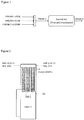
- the thermal reactor is represented schematically in Figure 1 .
- the simulation data are reported in the following table 1.
- An alternative configuration of the reactor is the proposed regenerative (energetically integrated) thermal reactor and is schematically represented in Figure 2 .
- the reactor receives CO 2 and H 2 S reactant streams at a relatively low temperature (e.g. 250°C).
- This feedstock is preheated (e.g., up to 700°C) with flue gases leaving the furnace.
- oxygen is fed to further increase the temperature up to the desired value (1300-1550°C). Flue gases are then cooled down, by exchanging heat with inlet gases. In this way a significant heat recovery is achieved, and the oxygen amount required to sustain the production of syngas is decidedly lower than that required in the thermal reactor.
- the following data are related to the proposed reaction conducted at 1300°C, 1.8 bar and 1 s residence time. Whenever the feedstock temperature is lower than the reaction temperature, additional O 2 is needed to increase the temperature itself.
- Oxygen quantity is less due to the amount of CO2 that works as Oxygen basin for H2S oxidation.
- Flue gases coming from the reactor are cooled down and syngas is separated from the other compounds namely H 2 S, CO 2 , SO 2 , H 2 O and S 2 .
- the process of the invention is preferably carried out in a productive unit that, besides the regenerative thermal reactor, it further comprises at least one of conversion/condensation/ compression sections allowing the separation of flue gases from said reactors.
- This separation can be realized in different ways, depending on the use of the different streams that, besides syngas, may be utilized industrially, and the production site, wherein the production unit for carrying out the process according to the invention is integrated with.
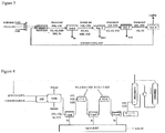
- FIG 3 a preferred embodiment is depicted of an independent productive unit used for carrying out the process according to the present invention.
- a regenerative thermal reactor acid gas (mainly H 2 S), CO 2 and oxygen (O 2 ) or combustion air or other fuel mixture are fed.
- acid gas mainly H 2 S
- CO 2 and oxygen O 2
- combustion air or other fuel mixture are fed.
- CO 2 reduction to CO occurs, with H 2 formation through H 2 S pyrolysis, thereby producing syngas.
- S 2 , SO 2 and H 2 O form as by products.
- Flue gases are cooled down in a waste heat boiler not represented in the figure. Cooling down must be sufficiently quick to avoid any recombination reactions among flue gases ( Manenti et al., Design of SRU thermal reactor and waste heat boiler considering recombination reactions, Procedia Engineering, 42, 414-421, 2012 ).
- SO 2 can be used in sulfuric acid production processes. As syngas production is always associated with a compression thereof at different tens of atmospheres, no further operating cost is required if SO 2 condensation occurs by pressure increase. For example syngas is compressed up to 80 bar or more for methanol synthesis ( Manenti et al., Considerations on the Steady-state Modeling of Methanol Synthesis Fixed-Bed Reactor, Chemical Engineering Science, 66(2), 152-162, 2011 ).
- the process of the invention is able to exhaust and increase the values of two by products like H 2 S and CO 2 having a strong environmental impact, thereby producing syngas with different CO/H 2 ratios; in addition the process of the invention, besides being energetically sustainable shows high conversion yields.
- the process of the invention is particularly useful for increasing the performances and profits of sulfur recovery units.
- the typical scheme of a sulfur recovery unit is depicted in Figure 4 .
- the acid gas to be treated is fed with non stoichiometric combustion air to a Claus furnace wherein part of H 2 S is converted to SO 2 according to the following reaction.
- the reaction is generally conducted at temperatures higher than 1000°C, with temperatures that may be higher than 1500°C in the presence of ammonia fractions in the acid gas stream.
- flue gas When leaving Claus furnace flue gas is cooled down to 300°C in a waste heat boiler with production of medium pressure vapor.
- a condenser downstream the waste heat boiler completes cool down by separating sulfur by condensation. Condensed sulfur is sent to liquid sulfur pit.
- the stream, thus free from sulfur, mainly consisting of H 2 S, SO 2 and H 2 O enters the first Claus catalytic converter CC1, wherein the following reaction occurs: R5: 2 H 2 S + SO 2 ⁇ 3/2S 2 + H 2 O
- Tail residue usually contains a small percentage of unconverted H 2 S (for example when molar ratios H 2 S/SO 2 higher than 2 are present in flue gases leaving Claus furnace). This residue is then washed with solvent for residual H 2 S abatement. H 2 S is then released from the stripper head and upstream recycled at Claus furnace feed, in addition to freshly fed acid gas.
- the mixture containing CO 2 , H 2 S, SO 2 , H 2 O and syngas is fed at the catalytic train CC1-CC2, wherein the Claus reaction R5 occurs.
- Syngas is inert both on the catalytic bed (not titanium based catalyst) and in intermediate sulfur condensing and removal operating conditions. Therefore flue gases coming from the third condenser Cond are unconverted CO 2 , H 2 S and syngas.
- Syngas is recovered at the top of the amine washing column ( ABSORBER in fig. 5 ), whereas H 2 S and CO 2 are recovered at the top of the stripper ( STRIPPER in the same figure) and recycled upstream the reactor.
- the operating unit to carry out the process of the invention integrated with Claus sulfur recovery unit allows to exhaust CO 2 by H 2 S reduction, thereby coproducing syngas and elemental sulfur.
- a production unit of sulfuric acid is schematically represented in Figure 6 .
- the production process encompasses the primary oxidation of sulfurated compounds, for example acid gas (H 2 S) according to the above mentioned global reaction R4: H 2 S + 1.5O 2 ⁇ SO 2 + H 2 O,
- the process according to the present invention may be integrated with the aforementioned process.
- the insertion of an independent operating unit to carry out the process of the invention in a possible revamp is reported in Fig. 7 .
- the thermal furnace of direct oxidation of H 2 S to SO 2 according to the aforementioned reaction R4 is replaced by the reactor indicated with NEW in Figure 7 , preferably a regenerative thermal reactor, wherein the process according to the present invention is carried out and from which SO 2 is in any case obtained.
- Natural gas is extracted by gases wells in the form of a gas or a volatile product released by liquid masses or porous solids. In any case it is a mixture of the so called light and volatile hydrocarbon compounds, in part defined as incondensable (i.e. methane) because of their very low condensation temperature.
- incondensable i.e. methane
- Natural gas contains a more or less marked presence of H 2 S and CO 2 according to the location of the specific deposit. For example Kashgan site in Ukraine, one of the world largest gas natural deposit, has an elevated amount of H 2 S (about 20% on the total natural gas content). Therefore the need is felt to purify natural gases from CO 2 and H 2 S and the most known technology to remove these contaminants is the amine sweetening (washing) previously mentioned.
- the process of the invention is particularly attractive for sequestering and converting CO 2 and H 2 S coming also from different streams and processes, thereby producing syngas as well as elemental sulfur in case the invention is integrated with sulfur recovery units.
- the process of the invention is even more attractive in case the deposits are already provided with amine washing columns, which the reactor, preferably a regenerative thermal reactor, to carry out the process according to the present invention may be connected to.
- Production unit integrated in a production unit for producing methanol 4.
- the invention allows to produce syngas for methanol synthesis occurring according to the overall reaction ( Manenti et al., Considerations on the Steady-state Modeling of Methanol Synthesis Fixed-Bed Reactor, Chemical Engineering Science, 66(2), 152-162, 2011 ): R8: CO + 2 H 2 ⁇ CH 3 OH
- An independent operating unit comprising a reactor, preferably a regenerative thermal reactor, to carry out the process according to the present invention allows to obtain syngas to be used in methanol production.
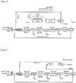
- Figure 8 reports a scheme of an operating unit for example to produce methanol according to Lurgi, Casale and Davy Process Technology ( Manenti et al., Considerations on the Steady-state Modeling of Methanol Synthesis Fixed-Bed Reactor, Chemical Engineering Science, 66(2), 152-162, 2011 ).
- CO 2 reverse water gas shift reaction
- NW reverse water gas shift reaction
- An alternative operating unit to carry out the process of the invention integrated with Claus operating unit may be also encompassed to be associated with a methanol plant production.
- Syngas is the starting reactant of Fischer Tropsch gas-to-liquid processes. In these processes, syngas is transformed into hydrocarbon compounds with progressively longer chains (indicated with the single unit -[CH 2 ]- according to the overall reaction: R9: CO + 2 H 2 ⁇ -[CH 2 ]- + H 2 O.
- syngas prepared with the process according to the present invention in the reactor NEW and purified by passing it through the 4 separation sections Sep1-Sep4 may be used as starting reactant in the Fischer Tropsch gas-to-liquid process as reported in Figure 9 .
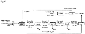
- Coal gasification reactor receives coal, steam and oxygen as reactants to produce syngas.
- Gasification by products are CO 2 and H 2 S (due to the presence of sulfur in loaded coal) and may be fed at the reactor NEW, preferably a regenerative thermal reactor, wherein the process according to the present invention is carried out, thereby increasing coal syngas production.
Landscapes
- Chemical & Material Sciences (AREA)
- Organic Chemistry (AREA)
- Inorganic Chemistry (AREA)
- Chemical Kinetics & Catalysis (AREA)
- Health & Medical Sciences (AREA)
- General Health & Medical Sciences (AREA)
- Engineering & Computer Science (AREA)
- Combustion & Propulsion (AREA)
- Carbon And Carbon Compounds (AREA)
- Industrial Gases (AREA)
- Gas Separation By Absorption (AREA)
- Organic Low-Molecular-Weight Compounds And Preparation Thereof (AREA)
Claims (15)
- Ein Verfahren zur Herstellung von Synthesegas aufweisend die endothermische Reaktion zwischen CO2 und H2S, nach folgendem insgesamt theoretischen Reaktionsschema
R1: CO2 + 2H2S → CO + H2 + S2 + H2O;
wobei:i) die Energieversorgung erfolgt durch exothermische Oxidation eines Teils des H2S zu SO2 nach folgendem Reaktionsschema:
R2: H2S + 1.5O2 → SO2 + H2O
ii) die Menge an zugeführtem Sauerstoff zur Durchführung von R2 zwischen 5Vol.-% und 25Vol.-% über das gesamte Volumen der gasförmigen Mischung der zugeführten Edukte beträgt;iii) das besagte Verfahren bei einer zwischen 800 und 1550°C liegenden Temperaturin einer Produktionseinheit durchgeführt wird, umfassend:• einen regenerativen thermischen Strömungsreaktor oder einen Thermoreaktor (NEU),• zumindest einen Trennabschnitt (Sep.1-Sep4, CC1-CC2, COND, ABSORBER, STRIPPER) für die verschiedenen Bestandteile der gasförmigen Mischung, die den besagten Thermoreaktor oder den regenerativen thermischen Strömungsreaktor verlassen, und• zumindest einen Abschnitt zur Recyclierung der nicht umgesetzten H2S und CO2. - Das Verfahren nach Anspruch 1, wobei die Menge an zugeführtem Sauerstoff, bei einer sehr wirksamen Regeneration zwischen 5% und 15% beträgt.
- Das Verfahren nach irgendeinem der Ansprüche 1 oder 2, wobei die Reaktionstemperatur zwischen 850°C und 1550°C für zwischen 0.1s und 3s liegende Residenzzeiten beträgt.
- Das Verfahren nach Anspruch 3, wobei die besagte Reaktionstemperatur zwischen 1300°C und 1550°C beträgt, um die maximale Umsetzung von CO2 und H2S zu erhalten.
- Das Verfahren nach Anspruch 3, wobei die Reaktionstemperatur zwischen 850°C und 1100°C beträgt, um ein Synthesegas mit höheren H2/CO-Verhältnissen zu erhalten.
- Das Verfahren nach irgendeinem der Ansprüche von 1 bis 5, wobei der besagte regenerative thermische Strömungsreaktor folgendes aufweist:a) einen regenerativen Abschnitt, der ein rohrförmiger PFR ist, in dem die zugeführten Gase vorgewärmt werden und durch den die Gase mit einer turbulenten Strömung fließenb) einen thermischen Abschnitt, der ein PFR ist, in dem die Reaktionen R1 und R2 stattfinden und durch den die Gase mit einer turbulenten Strömung fließen,wobei stromabwärts des besagten regenerativen Thermoreaktors optionell ein Abhitzekessel vorgesehen ist.
- Das Verfahren nach irgendeinem der Ansprüche von 1 bis 5, wobei der besagte Thermoreaktor ein PFR ist, durch den die Gase in eine turbulente Strömung übergehen.
- Das Verfahren nach Anspruch 6, wobei der besagte Abhitzekessel die den Reaktor verlassenden Gase aufnimmt und die besagten Gase auf der Rohrseite abkühlen während Mittel- und Hochdruckdämpfe auf der Mantelseite erzeugt werden.
- Das Verfahren nach irgendeinem der Ansprüche von 1 bis 8, wobei der Reaktorabfluss in einem Trennabschnitt aufgereinigt wird der folgendes aufweist:• einen ersten Trennabschnitt (Sep.1), wobei Schwefel von der gasförmigen Mischung durch Abkühlung abgetrennt und in einem geeigneten Tank aufgefangen wird;• einen zweiten Trennabschnitt (Sep.2), wobei die den besagten ersten Trennabschnitt (Sep.1) verlassende und CO, H2, H2O, SO2 und CO2, sowie nicht umgesetztes H2S und, falls das Verfahren in Gegenwart von Luft durchgeführt wird, möglicherweise Stickstoff enthaltende gasförmige Mischung abgekühlt wird, um die Trennung des Wassers durch Kondensation zu ermöglichen,• einen möglichen dritten Trennabschnitt (Sep.3), wobei SO2 von der gasförmigen Mischung durch Waschen oder chemische Umwandlung getrennt wird,• einen vierten Trennabschnitt (Sep. 4), wobei die den besagten dritten Trennabschnitt (Sep. 3) verlassende und H2S, CO2, CO und H2 enthaltende Mischung gewaschen wird, um das Synthesegas von den noch nicht umgesetzten Edukten zu trennen, die zurückgewonnen und dann zum Reaktor recycliert werden,die besagten Trennabschnitte sich miteinander kombinieren oder integrieren lassen.
- Das Verfahren nach irgendeinem der Ansprüche von 1 bis 8, wobei die in den Reaktor (NEU) eingeführten Gase H2S, O2 oder Luft und CO2 sind und wobei die den besagten Reaktor verlassenden Gase in einem Dampfrückgewinnungskessel (ABHITZEKESSEL) abgekühlt und dann in einen ersten Kondensator (Cond) einer Claus-Anlage zur Schwefelgewinnung, in eine Schwefelgrube (SCHWEFELGRUBE) geleitet werden, während die den besagten Kondensator verlassenden Gase in einen katalytischen Umwandlungsabschnitt geleitet werden, wo folgende Reaktion durchgeführt wird:
R5: 2H2S + SO2 → 3/2S2 + H2O
der besagte katalytische Umwandlungsabschnitt zumindest 1 katalytischen Konverter (CC1) und (CC2) umfasst, die hintereinander angeordnet und durch zumindest 1 Kondensator (Cond) beabstandet sind, um die teilweise Rückgewinnung von in jedem Konverter erzeugten Schwefel zu erlauben; wobei der besagte Schwefel in die vorgenannte Schwefelgrube geleitet wird und die gasförmige Mischung den letzten Kondensator (Cond) des besagten katalytischen Umwandlungsabschnitts verlässt und CO, H2, CO2, H2S umfasst, und möglicherweise Stickstoff durch einen Hydrierreaktor und einen Löschturm und dann in eine Lösungsmittel-Waschsäule (ABSORBER) fließt, wobei die besagte gasförmige Mischung mit Aminen gewaschen wird, um die nicht umgesetzten CO2 und H2S am Kopf eines Strippers (STRIPPER) zurückzugewinnen und zum regenerativen/thermischen Reaktor (NEU) recycliert wird, während das Synthesegas am Kopf der besagten Lösungsmittel-Waschsäule rückgewonnen wird. - Das Verfahren nach irgendeinem der Ansprüche von 1 bis 9, in dem das aus dem dritten Trennabschnitt (Sep. 3) kommende SO2 einem Reaktor R7 zugeführt wird, wo folgende Reaktion durchgeführt wird
R6: SO2 + 0.5O2 → SO3
und das so gebildete und den Reaktor R7 verlassende SO3 in Gegenwart von Wasser im Reaktor R8 unter Bildung von Schwefelsäure nach folgendem Reaktionsschema umgesetzt wird:
R7: SO3 + H2O → H2SO4
- Das Verfahren nach irgendeinem der Ansprüche von 1 bis 9, in dem das den vierten Trennabschnitt (Sep 4) verlassende Synthesegas in eine Produktionsanlage zur Herstellung von Methanol geleitet wird.
- Das Verfahren nach irgendeinem der Ansprüche von 1 bis 9, in dem die Edukte CO2 und H2S aus Erdgaslagerstätten gewonnen werden.
- Das Verfahren nach irgendeinem der Ansprüche von 1 bis 9, in dem das den vierten Trennabschnitt (Sep 4) verlassende Synthesegas einer Produktionsanlage zugeführt wird zur Herstellung von Benzin und Diesel durch das Fischer-Tropsch-Verfahren (Gas-to-liquid).
- Das Verfahren nach irgendeinem der Ansprüche von 1 bis 9, in dem die Edukte CO2 und H2S ganz oder teilweise von einer Kohlevergasungseinheit kommen.
Applications Claiming Priority (2)
| Application Number | Priority Date | Filing Date | Title |
|---|---|---|---|
| IT001322A ITMI20131322A1 (it) | 2013-08-02 | 2013-08-02 | Processo di riduzione di co2 per produzione di gas di sintesi. |
| PCT/IB2014/063593 WO2015015457A1 (en) | 2013-08-02 | 2014-07-31 | Syngas production by co2 reduction process |
Publications (2)
| Publication Number | Publication Date |
|---|---|
| EP3027552A1 EP3027552A1 (de) | 2016-06-08 |
| EP3027552B1 true EP3027552B1 (de) | 2019-08-28 |
Family
ID=49304128
Family Applications (1)
| Application Number | Title | Priority Date | Filing Date |
|---|---|---|---|
| EP14777817.9A Active EP3027552B1 (de) | 2013-08-02 | 2014-07-31 | Herstellung von syngas durch co2-reduktionsverfahren |
Country Status (9)
| Country | Link |
|---|---|
| US (1) | US9630839B2 (de) |
| EP (1) | EP3027552B1 (de) |
| CN (1) | CN105531222B (de) |
| CA (1) | CA2918458C (de) |
| DK (1) | DK3027552T3 (de) |
| EA (1) | EA031340B1 (de) |
| ES (1) | ES2754263T3 (de) |
| IT (1) | ITMI20131322A1 (de) |
| WO (1) | WO2015015457A1 (de) |
Families Citing this family (9)
| Publication number | Priority date | Publication date | Assignee | Title |
|---|---|---|---|---|
| US10532930B2 (en) * | 2016-07-21 | 2020-01-14 | Haldor Topsoe A/S | Method for production of sulfuric acid from sulfur containing feeds with gas quenching |
| WO2018127852A1 (en) | 2017-01-09 | 2018-07-12 | Sabic Global Technologies B.V. | Carbon monoxide, hydrogenm sulfur dioxide and elemental sulfur production from carbon dioxide reduction by hydrogen sulfide |
| IT201700001505A1 (it) | 2017-01-09 | 2018-07-09 | Milano Politecnico | Reattore catalitico a concentrazione solare. |
| US10889757B2 (en) * | 2017-10-19 | 2021-01-12 | Fujifilm Electronic Materials U.S.A., Inc. | Etching compositions |
| IT201900006957A1 (it) | 2019-05-17 | 2020-11-17 | Milano Politecnico | Forno per campi gas, per raffinerie e per il processo di reforming |
| IT201900006953A1 (it) * | 2019-05-17 | 2020-11-17 | Milano Politecnico | Forno per campi gas, per raffinerie e per il processo di reforming |
| EP4108739A1 (de) | 2021-06-21 | 2022-12-28 | TotalEnergies OneTech | Verfahren zur aufnahme von co2 in kohlenwasserstoffe |
| US12116326B2 (en) | 2021-11-22 | 2024-10-15 | Saudi Arabian Oil Company | Conversion of hydrogen sulfide and carbon dioxide into hydrocarbons using non-thermal plasma and a catalyst |
| US12515950B2 (en) | 2024-01-02 | 2026-01-06 | Saudi Arabian Oil Company | H2 recovery and CO2 separation using membrane |
Family Cites Families (4)
| Publication number | Priority date | Publication date | Assignee | Title |
|---|---|---|---|---|
| US4171347A (en) | 1975-08-18 | 1979-10-16 | Union Oil Company Of California | Catalytic incineration of hydrogen sulfide from gas streams |
| GB8318098D0 (en) * | 1983-07-04 | 1983-08-03 | Shell Int Research | Oxidation of hydrogen sulphide to elemental sulphur |
| US4999178A (en) * | 1988-12-08 | 1991-03-12 | Bowman Melvin G | Thermochemical cycle for splitting hydrogen sulfide |
| CN102553407B (zh) * | 2012-01-15 | 2013-11-06 | 浙江大学 | 热化学循环反应体系分解co2和h2o的方法及装置 |
-
2013
- 2013-08-02 IT IT001322A patent/ITMI20131322A1/it unknown
-
2014
- 2014-07-31 CA CA2918458A patent/CA2918458C/en active Active
- 2014-07-31 DK DK14777817T patent/DK3027552T3/da active
- 2014-07-31 US US14/907,573 patent/US9630839B2/en active Active
- 2014-07-31 EA EA201600161A patent/EA031340B1/ru not_active IP Right Cessation
- 2014-07-31 WO PCT/IB2014/063593 patent/WO2015015457A1/en not_active Ceased
- 2014-07-31 CN CN201480043519.6A patent/CN105531222B/zh not_active Expired - Fee Related
- 2014-07-31 ES ES14777817T patent/ES2754263T3/es active Active
- 2014-07-31 EP EP14777817.9A patent/EP3027552B1/de active Active
Non-Patent Citations (1)
| Title |
|---|
| None * |
Also Published As
| Publication number | Publication date |
|---|---|
| ES2754263T3 (es) | 2020-04-16 |
| CA2918458A1 (en) | 2015-02-05 |
| ITMI20131322A1 (it) | 2015-02-03 |
| CN105531222B (zh) | 2018-11-06 |
| WO2015015457A1 (en) | 2015-02-05 |
| DK3027552T3 (da) | 2019-11-25 |
| EA201600161A1 (ru) | 2016-06-30 |
| CN105531222A (zh) | 2016-04-27 |
| EP3027552A1 (de) | 2016-06-08 |
| US20160185596A1 (en) | 2016-06-30 |
| CA2918458C (en) | 2021-07-06 |
| US9630839B2 (en) | 2017-04-25 |
| EA031340B1 (ru) | 2018-12-28 |
Similar Documents
| Publication | Publication Date | Title |
|---|---|---|
| EP3027552B1 (de) | Herstellung von syngas durch co2-reduktionsverfahren | |
| CN1228238C (zh) | 生产氨/尿素的气化工艺 | |
| US7655213B2 (en) | Direct oxidation of sulfur with carbon dioxide recycle | |
| KR102637923B1 (ko) | 산업 공정으로부터 co2 배출물을 감소시키기 위한 방법 및 시스템 | |
| EA033955B1 (ru) | Интегрированный процесс получения стабилизированной формальдегидом мочевины | |
| SA519410066B1 (ar) | عملية لإنتاج الأمونيا باستخدام عملية التحول المتقدمة | |
| CN110049944B (zh) | 从源自于废物气化的合成气中制备纯氢气的方法和相关装置 | |
| CN102238995A (zh) | 用于气体料流净化的集成的暖气体脱硫作用和气体轮换反应 | |
| CN100396662C (zh) | 一体化的尿素制造设备和方法 | |
| JP2012512182A (ja) | オレフィン並びにアンモニア及び尿素の製造のための中間体の製造のための統合的方法 | |
| CA2835150A1 (en) | Zero emissions sulphur recovery process with concurrent hydrogen production | |
| US8273323B2 (en) | Hydrogen production method | |
| KR102892862B1 (ko) | 합성 가스 생성을 위한 로 및 공정 | |
| US7854915B2 (en) | Method of producing sulfuric acid and installation for carrying out the method | |
| JP2021510666A (ja) | 硫化水素を介した水分解による水素ガスと二酸化硫黄の製造 | |
| CN107099348A (zh) | 利用煤炭地下气化产品气生产合成天然气的方法 | |
| JP2023028524A (ja) | メタノールの製造方法 | |
| WO2020234708A1 (en) | Furnace and process for synthesis gas production | |
| WO2015015463A1 (en) | Process and relating plant for the production of hydrogen | |
| RU2825953C1 (ru) | Система синтеза аммиака с низким выбросом диоксида углерода и регулированием неравновесия мочевины | |
| JP2025507538A (ja) | 合成ガスから液体炭化水素を製造する方法 | |
| CN119793155A (zh) | 一种含硫尾气回收单质硫联产甲醇的工艺系统 | |
| EA043398B1 (ru) | Печь и способ получения синтез-газа | |
| WO2019205055A1 (zh) | 一种低温甲醇洗单元与多套克劳斯单元的尾气循环联用的方法与设备 |
Legal Events
| Date | Code | Title | Description |
|---|---|---|---|
| PUAI | Public reference made under article 153(3) epc to a published international application that has entered the european phase |
Free format text: ORIGINAL CODE: 0009012 |
|
| 17P | Request for examination filed |
Effective date: 20160121 |
|
| AK | Designated contracting states |
Kind code of ref document: A1 Designated state(s): AL AT BE BG CH CY CZ DE DK EE ES FI FR GB GR HR HU IE IS IT LI LT LU LV MC MK MT NL NO PL PT RO RS SE SI SK SM TR |
|
| AX | Request for extension of the european patent |
Extension state: BA ME |
|
| DAX | Request for extension of the european patent (deleted) | ||
| STAA | Information on the status of an ep patent application or granted ep patent |
Free format text: STATUS: EXAMINATION IS IN PROGRESS |
|
| 17Q | First examination report despatched |
Effective date: 20170728 |
|
| GRAP | Despatch of communication of intention to grant a patent |
Free format text: ORIGINAL CODE: EPIDOSNIGR1 |
|
| STAA | Information on the status of an ep patent application or granted ep patent |
Free format text: STATUS: GRANT OF PATENT IS INTENDED |
|
| INTG | Intention to grant announced |
Effective date: 20190524 |
|
| GRAS | Grant fee paid |
Free format text: ORIGINAL CODE: EPIDOSNIGR3 |
|
| GRAA | (expected) grant |
Free format text: ORIGINAL CODE: 0009210 |
|
| STAA | Information on the status of an ep patent application or granted ep patent |
Free format text: STATUS: THE PATENT HAS BEEN GRANTED |
|
| AK | Designated contracting states |
Kind code of ref document: B1 Designated state(s): AL AT BE BG CH CY CZ DE DK EE ES FI FR GB GR HR HU IE IS IT LI LT LU LV MC MK MT NL NO PL PT RO RS SE SI SK SM TR |
|
| REG | Reference to a national code |
Ref country code: GB Ref legal event code: FG4D |
|
| REG | Reference to a national code |
Ref country code: CH Ref legal event code: EP |
|
| REG | Reference to a national code |
Ref country code: DE Ref legal event code: R096 Ref document number: 602014052583 Country of ref document: DE |
|
| REG | Reference to a national code |
Ref country code: AT Ref legal event code: REF Ref document number: 1172168 Country of ref document: AT Kind code of ref document: T Effective date: 20190915 |
|
| REG | Reference to a national code |
Ref country code: IE Ref legal event code: FG4D |
|
| REG | Reference to a national code |
Ref country code: DK Ref legal event code: T3 Effective date: 20191118 |
|
| REG | Reference to a national code |
Ref country code: NL Ref legal event code: FP |
|
| REG | Reference to a national code |
Ref country code: LT Ref legal event code: MG4D |
|
| PG25 | Lapsed in a contracting state [announced via postgrant information from national office to epo] |
Ref country code: FI Free format text: LAPSE BECAUSE OF FAILURE TO SUBMIT A TRANSLATION OF THE DESCRIPTION OR TO PAY THE FEE WITHIN THE PRESCRIBED TIME-LIMIT Effective date: 20190828 Ref country code: LT Free format text: LAPSE BECAUSE OF FAILURE TO SUBMIT A TRANSLATION OF THE DESCRIPTION OR TO PAY THE FEE WITHIN THE PRESCRIBED TIME-LIMIT Effective date: 20190828 Ref country code: NO Free format text: LAPSE BECAUSE OF FAILURE TO SUBMIT A TRANSLATION OF THE DESCRIPTION OR TO PAY THE FEE WITHIN THE PRESCRIBED TIME-LIMIT Effective date: 20191128 Ref country code: PT Free format text: LAPSE BECAUSE OF FAILURE TO SUBMIT A TRANSLATION OF THE DESCRIPTION OR TO PAY THE FEE WITHIN THE PRESCRIBED TIME-LIMIT Effective date: 20191230 Ref country code: HR Free format text: LAPSE BECAUSE OF FAILURE TO SUBMIT A TRANSLATION OF THE DESCRIPTION OR TO PAY THE FEE WITHIN THE PRESCRIBED TIME-LIMIT Effective date: 20190828 Ref country code: BG Free format text: LAPSE BECAUSE OF FAILURE TO SUBMIT A TRANSLATION OF THE DESCRIPTION OR TO PAY THE FEE WITHIN THE PRESCRIBED TIME-LIMIT Effective date: 20191128 Ref country code: SE Free format text: LAPSE BECAUSE OF FAILURE TO SUBMIT A TRANSLATION OF THE DESCRIPTION OR TO PAY THE FEE WITHIN THE PRESCRIBED TIME-LIMIT Effective date: 20190828 |
|
| PG25 | Lapsed in a contracting state [announced via postgrant information from national office to epo] |
Ref country code: IS Free format text: LAPSE BECAUSE OF FAILURE TO SUBMIT A TRANSLATION OF THE DESCRIPTION OR TO PAY THE FEE WITHIN THE PRESCRIBED TIME-LIMIT Effective date: 20191228 Ref country code: AL Free format text: LAPSE BECAUSE OF FAILURE TO SUBMIT A TRANSLATION OF THE DESCRIPTION OR TO PAY THE FEE WITHIN THE PRESCRIBED TIME-LIMIT Effective date: 20190828 Ref country code: RS Free format text: LAPSE BECAUSE OF FAILURE TO SUBMIT A TRANSLATION OF THE DESCRIPTION OR TO PAY THE FEE WITHIN THE PRESCRIBED TIME-LIMIT Effective date: 20190828 Ref country code: GR Free format text: LAPSE BECAUSE OF FAILURE TO SUBMIT A TRANSLATION OF THE DESCRIPTION OR TO PAY THE FEE WITHIN THE PRESCRIBED TIME-LIMIT Effective date: 20191129 Ref country code: LV Free format text: LAPSE BECAUSE OF FAILURE TO SUBMIT A TRANSLATION OF THE DESCRIPTION OR TO PAY THE FEE WITHIN THE PRESCRIBED TIME-LIMIT Effective date: 20190828 |
|
| REG | Reference to a national code |
Ref country code: AT Ref legal event code: MK05 Ref document number: 1172168 Country of ref document: AT Kind code of ref document: T Effective date: 20190828 |
|
| PG25 | Lapsed in a contracting state [announced via postgrant information from national office to epo] |
Ref country code: TR Free format text: LAPSE BECAUSE OF FAILURE TO SUBMIT A TRANSLATION OF THE DESCRIPTION OR TO PAY THE FEE WITHIN THE PRESCRIBED TIME-LIMIT Effective date: 20190828 |
|
| REG | Reference to a national code |
Ref country code: ES Ref legal event code: FG2A Ref document number: 2754263 Country of ref document: ES Kind code of ref document: T3 Effective date: 20200416 |
|
| PG25 | Lapsed in a contracting state [announced via postgrant information from national office to epo] |
Ref country code: PL Free format text: LAPSE BECAUSE OF FAILURE TO SUBMIT A TRANSLATION OF THE DESCRIPTION OR TO PAY THE FEE WITHIN THE PRESCRIBED TIME-LIMIT Effective date: 20190828 Ref country code: RO Free format text: LAPSE BECAUSE OF FAILURE TO SUBMIT A TRANSLATION OF THE DESCRIPTION OR TO PAY THE FEE WITHIN THE PRESCRIBED TIME-LIMIT Effective date: 20190828 Ref country code: EE Free format text: LAPSE BECAUSE OF FAILURE TO SUBMIT A TRANSLATION OF THE DESCRIPTION OR TO PAY THE FEE WITHIN THE PRESCRIBED TIME-LIMIT Effective date: 20190828 Ref country code: AT Free format text: LAPSE BECAUSE OF FAILURE TO SUBMIT A TRANSLATION OF THE DESCRIPTION OR TO PAY THE FEE WITHIN THE PRESCRIBED TIME-LIMIT Effective date: 20190828 |
|
| PG25 | Lapsed in a contracting state [announced via postgrant information from national office to epo] |
Ref country code: SM Free format text: LAPSE BECAUSE OF FAILURE TO SUBMIT A TRANSLATION OF THE DESCRIPTION OR TO PAY THE FEE WITHIN THE PRESCRIBED TIME-LIMIT Effective date: 20190828 Ref country code: CZ Free format text: LAPSE BECAUSE OF FAILURE TO SUBMIT A TRANSLATION OF THE DESCRIPTION OR TO PAY THE FEE WITHIN THE PRESCRIBED TIME-LIMIT Effective date: 20190828 Ref country code: SK Free format text: LAPSE BECAUSE OF FAILURE TO SUBMIT A TRANSLATION OF THE DESCRIPTION OR TO PAY THE FEE WITHIN THE PRESCRIBED TIME-LIMIT Effective date: 20190828 Ref country code: IS Free format text: LAPSE BECAUSE OF FAILURE TO SUBMIT A TRANSLATION OF THE DESCRIPTION OR TO PAY THE FEE WITHIN THE PRESCRIBED TIME-LIMIT Effective date: 20200224 |
|
| REG | Reference to a national code |
Ref country code: DE Ref legal event code: R097 Ref document number: 602014052583 Country of ref document: DE |
|
| PLBE | No opposition filed within time limit |
Free format text: ORIGINAL CODE: 0009261 |
|
| STAA | Information on the status of an ep patent application or granted ep patent |
Free format text: STATUS: NO OPPOSITION FILED WITHIN TIME LIMIT |
|
| PG2D | Information on lapse in contracting state deleted |
Ref country code: IS |
|
| 26N | No opposition filed |
Effective date: 20200603 |
|
| PG25 | Lapsed in a contracting state [announced via postgrant information from national office to epo] |
Ref country code: SI Free format text: LAPSE BECAUSE OF FAILURE TO SUBMIT A TRANSLATION OF THE DESCRIPTION OR TO PAY THE FEE WITHIN THE PRESCRIBED TIME-LIMIT Effective date: 20190828 |
|
| PG25 | Lapsed in a contracting state [announced via postgrant information from national office to epo] |
Ref country code: MC Free format text: LAPSE BECAUSE OF FAILURE TO SUBMIT A TRANSLATION OF THE DESCRIPTION OR TO PAY THE FEE WITHIN THE PRESCRIBED TIME-LIMIT Effective date: 20190828 |
|
| REG | Reference to a national code |
Ref country code: CH Ref legal event code: PL |
|
| REG | Reference to a national code |
Ref country code: BE Ref legal event code: MM Effective date: 20200731 |
|
| PG25 | Lapsed in a contracting state [announced via postgrant information from national office to epo] |
Ref country code: LU Free format text: LAPSE BECAUSE OF NON-PAYMENT OF DUE FEES Effective date: 20200731 Ref country code: CH Free format text: LAPSE BECAUSE OF NON-PAYMENT OF DUE FEES Effective date: 20200731 Ref country code: LI Free format text: LAPSE BECAUSE OF NON-PAYMENT OF DUE FEES Effective date: 20200731 |
|
| PG25 | Lapsed in a contracting state [announced via postgrant information from national office to epo] |
Ref country code: BE Free format text: LAPSE BECAUSE OF NON-PAYMENT OF DUE FEES Effective date: 20200731 |
|
| PG25 | Lapsed in a contracting state [announced via postgrant information from national office to epo] |
Ref country code: IE Free format text: LAPSE BECAUSE OF NON-PAYMENT OF DUE FEES Effective date: 20200731 |
|
| PG25 | Lapsed in a contracting state [announced via postgrant information from national office to epo] |
Ref country code: MT Free format text: LAPSE BECAUSE OF FAILURE TO SUBMIT A TRANSLATION OF THE DESCRIPTION OR TO PAY THE FEE WITHIN THE PRESCRIBED TIME-LIMIT Effective date: 20190828 Ref country code: CY Free format text: LAPSE BECAUSE OF FAILURE TO SUBMIT A TRANSLATION OF THE DESCRIPTION OR TO PAY THE FEE WITHIN THE PRESCRIBED TIME-LIMIT Effective date: 20190828 |
|
| PG25 | Lapsed in a contracting state [announced via postgrant information from national office to epo] |
Ref country code: MK Free format text: LAPSE BECAUSE OF FAILURE TO SUBMIT A TRANSLATION OF THE DESCRIPTION OR TO PAY THE FEE WITHIN THE PRESCRIBED TIME-LIMIT Effective date: 20190828 |
|
| PGFP | Annual fee paid to national office [announced via postgrant information from national office to epo] |
Ref country code: NL Payment date: 20250721 Year of fee payment: 12 |
|
| PGFP | Annual fee paid to national office [announced via postgrant information from national office to epo] |
Ref country code: ES Payment date: 20250826 Year of fee payment: 12 |
|
| PGFP | Annual fee paid to national office [announced via postgrant information from national office to epo] |
Ref country code: DK Payment date: 20250725 Year of fee payment: 12 Ref country code: DE Payment date: 20250722 Year of fee payment: 12 |
|
| PGFP | Annual fee paid to national office [announced via postgrant information from national office to epo] |
Ref country code: IT Payment date: 20250718 Year of fee payment: 12 |
|
| PGFP | Annual fee paid to national office [announced via postgrant information from national office to epo] |
Ref country code: GB Payment date: 20250722 Year of fee payment: 12 |
|
| PGFP | Annual fee paid to national office [announced via postgrant information from national office to epo] |
Ref country code: FR Payment date: 20250725 Year of fee payment: 12 |