EP3027345B2 - Method for machining tooth edges and machining station designed for this purpose - Google Patents
Method for machining tooth edges and machining station designed for this purpose Download PDFInfo
- Publication number
- EP3027345B2 EP3027345B2 EP14745075.3A EP14745075A EP3027345B2 EP 3027345 B2 EP3027345 B2 EP 3027345B2 EP 14745075 A EP14745075 A EP 14745075A EP 3027345 B2 EP3027345 B2 EP 3027345B2
- Authority
- EP
- European Patent Office
- Prior art keywords
- axis
- machining
- toothing
- tool
- tooth
- Prior art date
- Legal status (The legal status is an assumption and is not a legal conclusion. Google has not performed a legal analysis and makes no representation as to the accuracy of the status listed.)
- Active
Links
- 238000003754 machining Methods 0.000 title claims description 90
- 238000000034 method Methods 0.000 title claims description 25
- 238000005520 cutting process Methods 0.000 claims description 52
- 239000000463 material Substances 0.000 claims description 4
- 238000005096 rolling process Methods 0.000 claims description 4
- 238000010862 gear shaping Methods 0.000 claims description 2
- 238000012545 processing Methods 0.000 description 17
- 238000006073 displacement reaction Methods 0.000 description 4
- 230000008569 process Effects 0.000 description 4
- 238000013461 design Methods 0.000 description 3
- 230000008859 change Effects 0.000 description 2
- 230000006378 damage Effects 0.000 description 2
- 230000000694 effects Effects 0.000 description 2
- 238000003825 pressing Methods 0.000 description 2
- 208000027418 Wounds and injury Diseases 0.000 description 1
- 230000005540 biological transmission Effects 0.000 description 1
- 238000000354 decomposition reaction Methods 0.000 description 1
- 230000001419 dependent effect Effects 0.000 description 1
- 238000011161 development Methods 0.000 description 1
- 238000011982 device technology Methods 0.000 description 1
- 238000005516 engineering process Methods 0.000 description 1
- 239000011521 glass Substances 0.000 description 1
- 208000014674 injury Diseases 0.000 description 1
- 230000007246 mechanism Effects 0.000 description 1
- 238000012986 modification Methods 0.000 description 1
- 230000004048 modification Effects 0.000 description 1
- 230000002028 premature Effects 0.000 description 1
- 230000000630 rising effect Effects 0.000 description 1
Images


Classifications
-
- B—PERFORMING OPERATIONS; TRANSPORTING
- B23—MACHINE TOOLS; METAL-WORKING NOT OTHERWISE PROVIDED FOR
- B23F—MAKING GEARS OR TOOTHED RACKS
- B23F19/00—Finishing gear teeth by other tools than those used for manufacturing gear teeth
- B23F19/10—Chamfering the end edges of gear teeth
- B23F19/102—Chamfering the end edges of gear teeth by milling
-
- A—HUMAN NECESSITIES
- A47—FURNITURE; DOMESTIC ARTICLES OR APPLIANCES; COFFEE MILLS; SPICE MILLS; SUCTION CLEANERS IN GENERAL
- A47G—HOUSEHOLD OR TABLE EQUIPMENT
- A47G25/00—Household implements used in connection with wearing apparel; Dress, hat or umbrella holders
- A47G25/80—Devices for putting-on or removing boots or shoes, e.g. boot-hooks, boot-jacks
- A47G25/84—Shoe benches
- A47G25/86—Shoe benches with boot-pulling devices
-
- B—PERFORMING OPERATIONS; TRANSPORTING
- B23—MACHINE TOOLS; METAL-WORKING NOT OTHERWISE PROVIDED FOR
- B23F—MAKING GEARS OR TOOTHED RACKS
- B23F19/00—Finishing gear teeth by other tools than those used for manufacturing gear teeth
-
- B—PERFORMING OPERATIONS; TRANSPORTING
- B23—MACHINE TOOLS; METAL-WORKING NOT OTHERWISE PROVIDED FOR
- B23F—MAKING GEARS OR TOOTHED RACKS
- B23F19/00—Finishing gear teeth by other tools than those used for manufacturing gear teeth
- B23F19/02—Lapping gear teeth
-
- B—PERFORMING OPERATIONS; TRANSPORTING
- B23—MACHINE TOOLS; METAL-WORKING NOT OTHERWISE PROVIDED FOR
- B23F—MAKING GEARS OR TOOTHED RACKS
- B23F19/00—Finishing gear teeth by other tools than those used for manufacturing gear teeth
- B23F19/10—Chamfering the end edges of gear teeth
-
- B—PERFORMING OPERATIONS; TRANSPORTING
- B23—MACHINE TOOLS; METAL-WORKING NOT OTHERWISE PROVIDED FOR
- B23F—MAKING GEARS OR TOOTHED RACKS
- B23F21/00—Tools specially adapted for use in machines for manufacturing gear teeth
-
- B—PERFORMING OPERATIONS; TRANSPORTING
- B23—MACHINE TOOLS; METAL-WORKING NOT OTHERWISE PROVIDED FOR
- B23F—MAKING GEARS OR TOOTHED RACKS
- B23F5/00—Making straight gear teeth involving moving a tool relatively to a workpiece with a rolling-off or an enveloping motion with respect to the gear teeth to be made
- B23F5/12—Making straight gear teeth involving moving a tool relatively to a workpiece with a rolling-off or an enveloping motion with respect to the gear teeth to be made by planing or slotting
- B23F5/16—Making straight gear teeth involving moving a tool relatively to a workpiece with a rolling-off or an enveloping motion with respect to the gear teeth to be made by planing or slotting the tool having a shape similar to that of a spur wheel or part thereof
- B23F5/163—Making straight gear teeth involving moving a tool relatively to a workpiece with a rolling-off or an enveloping motion with respect to the gear teeth to be made by planing or slotting the tool having a shape similar to that of a spur wheel or part thereof the tool and workpiece being in crossed axis arrangement, e.g. skiving, i.e. "Waelzschaelen"
-
- B—PERFORMING OPERATIONS; TRANSPORTING
- B23—MACHINE TOOLS; METAL-WORKING NOT OTHERWISE PROVIDED FOR
- B23F—MAKING GEARS OR TOOTHED RACKS
- B23F5/00—Making straight gear teeth involving moving a tool relatively to a workpiece with a rolling-off or an enveloping motion with respect to the gear teeth to be made
- B23F5/20—Making straight gear teeth involving moving a tool relatively to a workpiece with a rolling-off or an enveloping motion with respect to the gear teeth to be made by milling
-
- B—PERFORMING OPERATIONS; TRANSPORTING
- B23—MACHINE TOOLS; METAL-WORKING NOT OTHERWISE PROVIDED FOR
- B23Q—DETAILS, COMPONENTS, OR ACCESSORIES FOR MACHINE TOOLS, e.g. ARRANGEMENTS FOR COPYING OR CONTROLLING; MACHINE TOOLS IN GENERAL CHARACTERISED BY THE CONSTRUCTION OF PARTICULAR DETAILS OR COMPONENTS; COMBINATIONS OR ASSOCIATIONS OF METAL-WORKING MACHINES, NOT DIRECTED TO A PARTICULAR RESULT
- B23Q15/00—Automatic control or regulation of feed movement, cutting velocity or position of tool or work
- B23Q15/007—Automatic control or regulation of feed movement, cutting velocity or position of tool or work while the tool acts upon the workpiece
-
- Y—GENERAL TAGGING OF NEW TECHNOLOGICAL DEVELOPMENTS; GENERAL TAGGING OF CROSS-SECTIONAL TECHNOLOGIES SPANNING OVER SEVERAL SECTIONS OF THE IPC; TECHNICAL SUBJECTS COVERED BY FORMER USPC CROSS-REFERENCE ART COLLECTIONS [XRACs] AND DIGESTS
- Y10—TECHNICAL SUBJECTS COVERED BY FORMER USPC
- Y10T—TECHNICAL SUBJECTS COVERED BY FORMER US CLASSIFICATION
- Y10T409/00—Gear cutting, milling, or planing
- Y10T409/10—Gear cutting
- Y10T409/101113—Gear chamfering or deburring
Definitions
- the invention relates to a method for processing the tooth edges formed between an end face and the tooth flanks of a tooth system, as well as a processing station designed for this purpose and a gear cutting machine having such a processing station.
- a substantially cylindrical machining tool which has at least one cutting edge, is clamped on a tool spindle. After radial infeed, a chamfer is created on the tooth edges of the toothing by machining intervention of this chamfering tool with one end face of the toothed workpiece.
- the cutting direction of the chamfering tool can always be directed towards the center of the toothing on both end faces of the toothed workpiece.
- the invention relates to tooth edge processing with a cutting creation of a chamfer on the tooth edge.
- US 2,683,399 A discloses a method for rounding the corners between tooth flanks and tooth head, in which a toothed tool is brought into engagement at an axes angle with the workpiece carrying the teeth to be rounded.
- JP S 618221 A discloses two chamfering cutters connected to each other via a scraper wheel and their axis of rotation at an axes angle in a joint machining of the workpiece.
- GB 818135 A discloses a method for rounding the corners of a work wheel formed at the cuts between the top and side surfaces of the tooth.
- DE 2 157 619 A discloses a device for deburring or breaking the edges on the tooth ends of gears, in which two toothed cutting tools clamped coaxially and non-rotatably with a guide wheel are brought into machining engagement with a workpiece at an axis cross angle.
- the present invention is based on the object of improving a method of the type mentioned at the outset, particularly with regard to greater flexibility, also with regard to the shape of the workpieces to be machined that carry the toothing.
- the invention is therefore one compared to that referred to above DE 10 2009 019 433
- the state of the art explained is based on completely different kinematics of the machine axes involved.
- the machining tool is geared, and the gear axis is at an axis crossing angle to the gear axis of the gear, the edges of which are being machined.
- the movement kinematics is therefore that of a helical gear transmission, which is characterized by a skewed arrangement of the respective axes of rotation.
- the axis cross angle is obtained by pivoting one of the axes of rotation around a connecting direction of the centers of the toothing to be machined and the machining tool (common perpendicular to the axes of rotation), starting from parallel axes of rotation.
- ⁇ The axis cross angle
- the meaning of the axis cross angle is already known to the gear specialist, for example through power skiving.
- a clear representation of the machine axes, kinematics and cutting conditions as well as definitions of terms occurring during power skiving is given, for example. B. in the EP 2 537 615 A1 given.
- the axis cross angle thus creates a cutting mechanism in which the cutting speed depends on the axis cross angle and also the speed of the processing tool.
- the cutting edges of the tool are formed by the edges of the tool teeth.
- the cutting direction of the cutting movement can therefore have a directional component caused by the non-zero axis cross angle, which runs along the tooth flank adjoining the machined tooth edge in the tooth width direction.
- a non-zero inclination angle of the axis of rotation of the machining tool is set relative to a plane orthogonal to the connecting direction between the centers of the toothing and the machining tool.
- the tool is thus tilted in the direction of the workpiece axis Z ( Fig. 2 ).
- the angle of inclination also corresponds to an inclination of the tool reference plane with respect to the contact plane.
- the resulting mutual axis position in the machining engagement can therefore be adjusted (starting from parallel axes) by rotating about two linearly independent axes of rotation.
- an axis cross angle can also be set by rotating about only one axis and a displacement with a displacement component can be carried out perpendicular to the connecting axis of the centers (previous common plumb line) and perpendicular to one of the rotation axes of the gearing and machining tool.
- Such a shift can be recognized by a non-zero offset between the axis cross point seen in the projection and the intervention area (touch point) of the machining.
- the originally set axis cross angle can be viewed as a decomposition into an effective axis cross angle and the inclination angle.
- connection direction between the centers is also a radial direction, which can also be used as an infeed axis direction in the method, for pure infeed or for a plunge feed.
- the axis cross angle is preferably at least 4°, more preferably at least 8°, in particular at least 12°. Furthermore, the axis cross angle should expediently not be more than 45°, preferably not more than 35°, in particular not more than 25°. This leads to sufficiently high cutting speeds while at the same time not placing too high demands on the design of the machining tool.
- angle of inclination it is preferred that this is at least 8°, preferably at least 16°, in particular at least 24°. On the other hand, it should not exceed 80°, preferably at most 60°, in particular at most 40°.
- This inclination angle adjustment especially in combination with the above axis cross angle adjustment, ensures a suitable course of the profile-forming contact lines.
- a factor that determines the cutting speed is the speed for rotation of the machining tool around its axis of rotation. With the remaining axes of movement set, this is preferably set so that the cutting speed is at least 10 m/min, preferably at least 30 m/min, in particular at least 50 m/min.
- the upper limit for the cutting speed is 450 m/min, preferably at most 300 m/min, in particular at most 200 m/min, also 150 m/min. This achieves a suitable compromise between machining times that are not too long on the one hand and sufficient tool life on the other.
- the profile-forming contact lines must be pushed over this entire tooth edge area of a tooth gap.
- the invention basically provides several options for this.
- the machining tool and the toothing to be machined can be allowed to carry out a relative movement with a directional component that is parallel to the toothing axis of the toothing to be machined. Similar to skiving, this can be, for example, a movement along the gear axis or along the tool axis. This variant is particularly advantageous for large angles of inclination. It is conceivable that some tooth edges of the toothing to be machined, at least some areas of these tooth edges, do not come into contact at all with some areas of the cutting edge areas provided on the tooth edges of the toothing of the machining tool, for example.
- the machining tool does not have to be fully toothed, even if this represents a preferred variant.
- a single tooth with a cutting edge would be sufficient.
- the axial feed movement speed would have to be chosen correspondingly low.
- the invention provides a processing station for processing the tooth edges formed between each end face and the tooth flanks of a toothing with the features of claim 8. Rolling engagement between the toothing to be machined and a toothing of the machining tool controls.
- the advantages of the processing station according to the invention result from the advantages of the method according to the invention.
- the processing station can thus preferably have a linear axis used for delivery, in particular a first machine axis with a directional component, in particular radially to the workpiece spindle axis.
- a machine axis is also expediently provided, with which a relative movement between the workpiece spindle and tool spindle with a movement component can act parallel to the workpiece spindle axis. On the one hand, this makes it possible to realize an axial feed movement.
- the axial position of the machining tool can be changed, which is particularly useful when machining workpieces with different tooth widths, and can also be used for axial mutual positioning between the machining of the tooth edges on one end face and that of the other end face.
- a non-zero inclination angle of the tool spindle axis can be adjusted relative to a plane that is orthogonal to the connecting direction between the centers of the toothing and the machining tool.
- a further machine rotation axis which has an axis used to adjust the axis cross angle and an axis component orthogonal to the workpiece spindle axis. This means that the axis cross angle and inclination angle are adjusted via two machine rotation axes.
- a second machine axis which has a component in a plane running orthogonally to the workpiece spindle axis, which is linearly independent of a projection of the first machine axis onto this plane.
- this can be a cross slide with a radial feed direction
- An axis cross angle originally set by rotation about the radial axis (X) ultimately receives an inclination component ⁇ due to the displacement of the shift slide in the Y direction, since the tool spindle axis orientation does not change during the displacement, but the connecting axis between the centers of the workpiece and tool does .
- the processing tool can preferably be disk-shaped, in particular with an axial dimension of not larger than 10 cm, preferably not larger than 7 cm, in particular not larger than 4 cm.
- the teeth of the machining tool are suitably ground with a step grinding pattern and therefore have a basic shape that is also often used for power skiving.
- the machining tool can have a structure that develops the effect of a feed movement parallel to the tool axis. This is preferably achieved in that the machining tool has areas with different heights of its (rake face) teeth measured on its axis of rotation. Since the toothing carries the rake surfaces with the cutting edges, the invention also discloses a machining tool that can be protected independently for machining the tooth edges formed between each end face and the tooth flanks of a toothing by cutting material removal from the tooth edges, in which the intended ones are attached to the cutting edges of the Machining tool adjacent rake surfaces of the respective teeth of the machining tool measured on the axis of rotation of the machining tool have different heights.
- the rake surfaces of the machining tool rise at least partially in a helical manner.
- the basic shape of the cutting surfaces can also be formed by step grinding.
- the pitch gained by increasing in one revolution is then, in addition to the relative position between the axes of rotation of the machining tool and the toothing, a determining factor for the expansion of the edge area formed without additional feed, over which the profile-forming contact lines run. It preferably corresponds to the tooth width offset of a profile line that occurs when passing through a tooth gap.
- the invention provides a gear cutting machine for processing gears with such a processing station.
- This can in particular be provided with a further work station, which is used to produce the toothing to be machined using the soft machining process, for example for hobbing, gear shaping or power skiving (gear skiving).
- the method according to the invention is also protected in the form of a control program.
- the method according to the invention can be used for the tooth edge processing of internal gears as well as external gears.
- FIG. 1 The machine axis kinematics on which the process is based are shown.
- a workpiece with a toothing 2 is in Fig. 1 oriented in such a way that its tooth axis Z runs vertically.
- the individual teeth of the toothing 2 are in the schematic representation of Fig. 1 not shown.
- In projection onto the paper plane of Fig. 1 that is , orthogonal to the radial feed direction In the exemplary embodiment shown, this is 20°.
- the axes X, Z and Y shown form a rectangular coordinate system for this exemplary embodiment.
- Fig. 2 The engagement conditions are still shown from the viewing direction Y, i.e. at 90° compared to the viewing direction in Fig. 1 rotated viewing direction.
- the machining tool 1 is also inclined relative to a plane orthogonal to the direction X, namely by the angle ⁇ , which here is 30 °.
- the tooth edges of the toothing 2 are machined, which are formed between the tooth flanks of the toothing 2 and the upper end face 3.
- the workpiece can be turned over so that the in Fig. 2 lower end face becomes the upper end face, while the tool position remains the same as when machining the in Fig. 2 situation presented.
- this mutual position between the workpiece and the tool can also be achieved by changing the position of the tool.
- the tool can be pivoted by the in Fig. 2 Axis designated by X can be realized by 180° or more.
- a second machine axis of rotation is not required to adjust the respective axis position. Rather, based on the in Fig. 3b
- the axis position shown which occurs during power skiving and in which, as seen in the projection, the engagement area between the workpiece and the tool is in the area of the axis cross point, also involves a shift movement of the tool (in Fig. 3 to the left). With this shift movement, the axis orientation of the tool axis does not change, but the center of the machining tool is moved.
- the plane orthogonal to the line connecting the centers, in Fig. 3b the paper plane is thus, figuratively speaking, tilted out of the paper plane in order to... Fig. 3a to stand vertically on the new connecting line again.
- the tool axis of rotation is then no longer in this plane, but is again inclined at an angle of inclination in the direction of the workpiece axis of rotation.
- Fig. 3a is the interlocking versus the representation of Fig. 3b omitted. This is intended to indicate that the profile of the machining tool for tooth edge machining does not correspond to the tooth profile of the in Fig. 3b Power skiving tool shown corresponds. Rather, the tool profile of the tooth edge processing tool is modified accordingly, since in order to create the chamfer the edge has to be broken in the front plane and the speed vector must then be parallel to the chamfer of the surface.
- Fig. 4 shown as an example, in which the solid line represents the tooth profile of the tool used for power skiving, while the dashed line shows the corresponding profile of the chamfering tool.
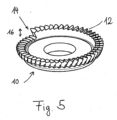
- machining tool 10 An axial tool movement during tooth edge machining on one end face could be dispensed with in a variant not according to the invention if the in Fig. 5 machining tool 10 shown is used. Its toothing 12 rises relative to the axis of rotation Z w in the form of a continuously rising helix and therefore has a height jump 16 at a point 14. A single complete rotation of the machining tool 10 about its axis of rotation results in the profile-forming contact lines being pushed fully over both tooth edges of a tooth gap in the toothing to be machined, which results in particularly time-saving tooth edge machining.
- the continuous helical shape is preferably optional; for example, several stepped areas could also be formed.
- a line element d ⁇ of a cutting edge of the tool is first considered in a simplified manner, which lies on a tooth edge of the toothing of the machining tool, i.e. in a plane orthogonal to the axis of rotation Z w of the machining tool.
- the direction vector of the cutting edge element d ⁇ can be described, for example, by (cos ⁇ , sin ⁇ , 0) where ⁇ represents the angle that the orientation of the cutting edge element d ⁇ has with a radial axis, for example the axis X w in the snapshot Rest system of the machining tool (X w , Y w , Z w ).
- a movement along the orientation of the cutting edge itself does not cause any cutting compared to a stationary workpiece, and the cutting edge element d ⁇ always moves in the plane orthogonal to the axis of rotation Z w .
- this is the basic machine axis constellation of power skiving, in which, based on the image of the tooth flank surfaces that have already been completed by power skiving in maximum radial infeed, the cutting direction is in the relative movement to the one that is also rotating and is to be machined Gearing must not have any component orthogonal to the tooth flank.
- the axis of rotation Z w in the spatially fixed system is also pivoted about the axis Y, namely by an angle of inclination ⁇ .
- the axis cross angle ⁇ which is different from zero, ensures that a cutting direction component that runs perpendicular to the tooth flank can be implemented, into which the sine of the additional inclination angle also enters in the preferred embodiment.
- the majority of the component of the cutting direction perpendicular to the tooth flank of the toothing to be machined is dependent on the factor sin ⁇ * sin ⁇ .
Description
Die Erfindung betrifft ein Verfahren zum Bearbeiten der zwischen einer Stirnseite und den Zahnflanken einer Verzahnung ausgebildeten Zahnkanten sowie eine dazu ausgelegte Bearbeitungsstation und eine eine solche Bearbeitungsstation aufweisende Verzahnungsmaschine.The invention relates to a method for processing the tooth edges formed between an end face and the tooth flanks of a tooth system, as well as a processing station designed for this purpose and a gear cutting machine having such a processing station.
Derartige Verfahren sind in der Technik bekannt, beispielsweise durch die
Um diesen Nachteilen entgegenzutreten, sind in der Technik mehrere Verfahren entwickelt worden. Ein solches Verfahren, das beispielsweise in der
Alternativ zu diesem Anfasen durch plastisches Drücken besteht die Möglichkeit, eine Fase an der Zahnkante durch Schneiden zu erzeugen. Gemäß der
Der vorliegenden Erfindung liegt dabei die Aufgabe zugrunde, ein Verfahren der eingangs genannten Art insbesondere im Hinblick auf eine höhere Flexibilität auch betreffend der Form der die Verzahnung tragenden, zu bearbeitenden Werkstücke zu verbessern.The present invention is based on the object of improving a method of the type mentioned at the outset, particularly with regard to greater flexibility, also with regard to the shape of the workpieces to be machined that carry the toothing.
Diese Aufgabe wird von der Erfindung in verfahrenstechnischer Hinsicht durch eine Weiterbildung des eingangs genannten Verfahrens mit den Merkmalen von Anspruch 1 gebildet.This object is achieved by the invention in terms of procedural engineering through a development of the method mentioned at the beginning with the features of
Der Erfindung liegt somit eine gegenüber dem oben mit Bezug auf
Durch den Achskreuzwinkel wird somit ein Schneidmechanismus erzeugt, bei dem die Schnittgeschwindigkeit von dem Achskreuzwinkel und auch der Drehzahl des Bearbeitungswerkzeugs abhängt. Die Schneidkanten des Werkzeugs sind durch die Kanten der Werkzeugverzahnung gebildet.The axis cross angle thus creates a cutting mechanism in which the cutting speed depends on the axis cross angle and also the speed of the processing tool. The cutting edges of the tool are formed by the edges of the tool teeth.
So kann die Schnittrichtung der Schneidbewegung eine durch den von Null verschiedenen Achskreuzwinkel bewirkte Richtungskomponente aufweisen, die entlang der an der bearbeiteten Zahnkante anschließenden Zahnflanke in Zahnbreitenrichtung verläuft.The cutting direction of the cutting movement can therefore have a directional component caused by the non-zero axis cross angle, which runs along the tooth flank adjoining the machined tooth edge in the tooth width direction.
Um der Schnittrichtung der Schneidbewegung eine orthogonal zur Zahnflanke verlaufende Richtungskomponente zu verleihen, wird erfindungsgemäß ein von Null verschiedener Neigungswinkel der Rotationsachse des Bearbeitungswerkzeugs gegenüber einer orthogonal zur Verbindungsrichtung zwischen den Zentren von Verzahnung und Bearbeitungswerkzeug stehenden Ebene eingestellt. Das Werkzeug wird somit in Richtung auf die Werkstückachse Z hin gekippt (
Die dadurch bestimmte gegenseitige Achslage im Bearbeitungseingriff läßt sich daher (ausgehend von parallelen Achsen) durch Drehung um zwei linear unabhängige Drehachsen einstellen. Es kann aber auch ein Achskreuzwinkel durch Drehung um nur eine Achse eingestellt werden und dazu eine Verschiebung mit Verschiebungskomponente senkrecht zur Verbindungsachse der Zentren (bisheriges Gemeinlot) und senkrecht zu einer von den Rotationsachsen von Verzahnung und Bearbeitungswerkzeug durchgeführt werden. Eine solcheVerschiebung erkennt man an einem von Null verschiedenen Offset zwischen dem in Projektion gesehenen Achskreuzpunkt und dem Eingriffsbereich (Berührpunkt) der Bearbeitung. Der ursprünglich eingestellte Achskreuzwinkel läßt sich nach dieser Verschiebung als Zerlegung in einen effektiven Achskreuzwinkel und den Neigungswinkel ansehen.The resulting mutual axis position in the machining engagement can therefore be adjusted (starting from parallel axes) by rotating about two linearly independent axes of rotation. However, an axis cross angle can also be set by rotating about only one axis and a displacement with a displacement component can be carried out perpendicular to the connecting axis of the centers (previous common plumb line) and perpendicular to one of the rotation axes of the gearing and machining tool. Such a shift can be recognized by a non-zero offset between the axis cross point seen in the projection and the intervention area (touch point) of the machining. After this shift, the originally set axis cross angle can be viewed as a decomposition into an effective axis cross angle and the inclination angle.
Bei der Verbindungsrichtung zwischen den Zentren handelt es sich zudem um eine Radialrichtung, die in dem Verfahren auch als Zustellachsrichtung nutzbar ist, für eine reine Zustellung oder für einen Tauchvorschub.The connection direction between the centers is also a radial direction, which can also be used as an infeed axis direction in the method, for pure infeed or for a plunge feed.
Bevorzugt beträgt der Achskreuzwinkel wenigstens 4°, weiter bevorzugt wenigstens 8°, insbesondere wenigstens 12°. Im Übrigen sollte der Achskreuzwinkel zweckmäßig nicht mehr als 45° betragen, bevorzugt nicht mehr als 35°, insbesondere nicht mehr als 25°. Dies führt zu ausreichend hohen Schnittgeschwindigkeiten bei gleichzeitig nicht zu hohen Anforderungen an die Auslegung des Bearbeitungswerkzeugs.The axis cross angle is preferably at least 4°, more preferably at least 8°, in particular at least 12°. Furthermore, the axis cross angle should expediently not be more than 45°, preferably not more than 35°, in particular not more than 25°. This leads to sufficiently high cutting speeds while at the same time not placing too high demands on the design of the machining tool.
Hinsichtlich des Neigungswinkels wird es bevorzugt, daß dieser weinigstens 8°, bevorzugt wenigstens 16°, insbesondere wenigstens 24° beträgt. Andererseits sollte er 80° nicht übersteigen, bevorzugt höchstens 60°, insbesondere höchstens 40° betragen. Diese Neigungswinkeleinstellung sorgt, insbesondere in Kombination mit der obigen Achskreuzwinkeleinstellung, für einen geeigneten Verlauf der profilbildenden Kontaktlinien.With regard to the angle of inclination, it is preferred that this is at least 8°, preferably at least 16°, in particular at least 24°. On the other hand, it should not exceed 80°, preferably at most 60°, in particular at most 40°. This inclination angle adjustment, especially in combination with the above axis cross angle adjustment, ensures a suitable course of the profile-forming contact lines.
Wie oben bereits erläutert ist ein die Schnittgeschwindigkeit mitbestimmender Faktor die Drehzahl für die Drehung des Bearbeitungswerkzeugs um seine Rotationsachse. Diese wird bei festgelegter Einstellung der übrigen Bewegungsachsen bevorzugt so eingestellt, daß die Schnittgeschwindigkeit wenigstens 10 m/min, bevorzugt wenigstens 30 m/min, insbesondere wenigstens 50 m/min beträgt. Als Obergrenze für die Schnittgeschwindigkeit ist 450 m/min, bevorzugt höchstens 300 m/min, insbesondere höchstens 200 m/min, auch 150 m/min vorgesehen. Damit wird ein geeigneter Kompromiß zwischen nicht zu hohen Bearbeitungszeiten einerseits und einer ausreichenden Werkzeugstandzeit andererseits erreicht.As already explained above, a factor that determines the cutting speed is the speed for rotation of the machining tool around its axis of rotation. With the remaining axes of movement set, this is preferably set so that the cutting speed is at least 10 m/min, preferably at least 30 m/min, in particular at least 50 m/min. The upper limit for the cutting speed is 450 m/min, preferably at most 300 m/min, in particular at most 200 m/min, also 150 m/min. This achieves a suitable compromise between machining times that are not too long on the one hand and sufficient tool life on the other.
Damit die Zahnflanken jedenfalls zwischen Fuß- und Kopfflanken einer vollständigen Bearbeitung unterliegen, sind insoweit die profilbildenden Kontaktlinien über diesen gesamten Zahnkantenbereich einer Zahnlücke zu schieben. Dazu sieht die Erfindung grundsätzlich mehrere Möglichkeiten vor.So that the tooth flanks are subject to complete machining, at least between the foot and head flanks, the profile-forming contact lines must be pushed over this entire tooth edge area of a tooth gap. The invention basically provides several options for this.
Zum einen kann man das Bearbeitungswerkzeug und die zu bearbeitende Verzahnung eine Relativbewegung mit einer zur Verzahnungsachse der zu bearbeitenden Verzahnung parallelen Richtungskomponente ausführen lassen. Diese kann, ähnlich wie beim Wälzschälen, z.B. eine Bewegung längs der Verzahnungsachse oder längs der Werkzeugachse sein. Diese Variante ist insbesondere bei großen Neigungswinkeln vorteilhaft. Es ist dabei denkbar, daß einige Zahnkanten der zu bearbeitenden Verzahnung, jedenfalls einige Bereiche dieser Zahnkanten mit einigen Bereichen der an den beispielsweise Zahnkanten der Verzahnung des Bearbeitungswerkzeugs vorgesehenen Schneidkantenbereichen überhaupt nicht in Berührung kommen.On the one hand, the machining tool and the toothing to be machined can be allowed to carry out a relative movement with a directional component that is parallel to the toothing axis of the toothing to be machined. Similar to skiving, this can be, for example, a movement along the gear axis or along the tool axis. This variant is particularly advantageous for large angles of inclination. It is conceivable that some tooth edges of the toothing to be machined, at least some areas of these tooth edges, do not come into contact at all with some areas of the cutting edge areas provided on the tooth edges of the toothing of the machining tool, for example.
Andererseits muß das Bearbeitungswerkzeug, auch wenn dies eine bevorzugte Variante darstellt, nicht voll verzahnt sein. Grundsätzlich würde ein einzelner mit Schneidkante versehener Zahn ausreichen. In diesem Fall wäre die axiale Vorschubbewegungsgeschwindigkeit entsprechend gering zu wählen.On the other hand, the machining tool does not have to be fully toothed, even if this represents a preferred variant. In principle, a single tooth with a cutting edge would be sufficient. In this case, the axial feed movement speed would have to be chosen correspondingly low.
Gemäß einer nicht erfindungsgemäßen Variante läßt sich auch eine diese Wirkung entfaltende Struktur in das Bearbeitungswerkzeug selbst einarbeiten. Genaueres hierzu wird weiter unten anhand der Vorrichtungsansprüche erläutert.According to a variant not according to the invention, a structure that develops this effect can also be incorporated into the processing tool itself. More details on this will be explained below based on the device claims.
Bei dieser Variante kann unter Umständen vollständig auf eine z.B. parallel zur Verzahnungsachse oder Werkzeugachse geführte Vörschubbewegung verzichtet werden. Dies ist insbesondere dann vorteilhaft, wenn das die zu bearbeitende Verzahnung aufweisende Werkstück noch eine nahegelegene Schulter aufweist, die durch die Zahnkantenbearbeitung nicht beeinträchtigt werden darf. Mehrere unterschiedliche Zähne des Werkzeugs kommen dann in Eingriff mit einer jeweiligen Lücke und bearbeiten dabei (segmentweise) die beiden Zahnkanten einer jeden Lücke (Überrollung).With this variant, it may be possible to completely dispense with a feed movement parallel to the gear axis or tool axis, for example. This is particularly advantageous if the workpiece containing the toothing to be machined also has a nearby shoulder that must not be affected by the tooth edge machining. Several different teeth of the tool then come into engagement with a respective gap and process (in segments) the two tooth edges of each gap (rollover).
In vorrichtungstechnischer Hinsicht stellt die Erfindung eine Bearbeitungsstation zur Bearbeitung der zwischen jeder Stirnseite und den Zahnflanken einer Verzahnung ausgebildeten Zahnkanten mit den Merkmalen von Anspruch 8 bereit. Wälzeingriff zwischen der zu bearbeitenden Verzahnung und einer Verzahnung des Bearbeitungswerkzeugs steuert.In terms of device technology, the invention provides a processing station for processing the tooth edges formed between each end face and the tooth flanks of a toothing with the features of claim 8. Rolling engagement between the toothing to be machined and a toothing of the machining tool controls.
Die Vorteile der erfindungsgemäßen Bearbeitungsstation ergeben sich aus den Vorteilen des erfindungsgemäßen Verfahrens. So kann die Bearbeitungsstation bevorzugt eine der Zustellung dienende Linearachse, insbesondere erste Maschinenachse mit einer Richtungskomponente, insbesondere radial zur Werkstückspindelachse, aufweisen. Zweckmäßig ist auch eine Maschinenachse vorgesehen, mit der eine Relativbewegung zwischen Werkstückspindel und Werkzeugspindel mit Bewegungskomponente parallel zur Werkstückspindelachse wirken kann. Damit läßt sich zum einen eine axiale Vorschubbewegung realisieren. Zum anderen läßt sich die axiale Position des Bearbeitungswerkzeugs verändern, was insbesondere bei der Bearbeitung von Werkstücken unterschiedlicher Verzahnungsbreite zweckmäßig ist, im Übrigen auch zur axialen gegenseitigen Positionierung zwischen der Bearbeitung der Zahnkanten an einer Stirnseite und der der anderen Stirnseite einsetzbar ist. Des Weiteren erfindungsgemäß ein von Null verschiedener Neigungswinkel der Werkzeugspindelachse gegenüber einer orthogonal zur Verbindungsrichtung zwischen den Zentren von Verzahnung und Bearbeitungswerkzeug stehenden Ebene einstellbar.The advantages of the processing station according to the invention result from the advantages of the method according to the invention. The processing station can thus preferably have a linear axis used for delivery, in particular a first machine axis with a directional component, in particular radially to the workpiece spindle axis. A machine axis is also expediently provided, with which a relative movement between the workpiece spindle and tool spindle with a movement component can act parallel to the workpiece spindle axis. On the one hand, this makes it possible to realize an axial feed movement. On the other hand, the axial position of the machining tool can be changed, which is particularly useful when machining workpieces with different tooth widths, and can also be used for axial mutual positioning between the machining of the tooth edges on one end face and that of the other end face. Furthermore, according to the invention, a non-zero inclination angle of the tool spindle axis can be adjusted relative to a plane that is orthogonal to the connecting direction between the centers of the toothing and the machining tool.
In einer denkbaren Ausführungsform ist eine weitere Maschinendrehachse vorgesehen, die eine zur der Einstellung des Achskreuzwinkels dienende Achse und zur Werkstückspindelachse orthogonale Achskomponente aufweist. Dadurch werden Achskreuzwinkel und Neigungswinkel über zwei Maschinendrehachsen eingestellt.In a conceivable embodiment, a further machine rotation axis is provided, which has an axis used to adjust the axis cross angle and an axis component orthogonal to the workpiece spindle axis. This means that the axis cross angle and inclination angle are adjusted via two machine rotation axes.
In einer anderen, nochmals bevorzugteren Ausführungsform ist allerdings eine zweite Maschinenachse vorgesehen, die eine Komponente in einer orthogonal zur Werkstückspindelachse laufenden Ebene aufweist, welche von einer Projektion der ersten Maschinenachse auf diese Ebene linear unabhängig ist. In einer zweckmäßigen Gestaltung kann dies ein Kreuzschlitten mit radialer Zustellrichtung X einerseits und dazu der auch zur Werkstückspindelachse orthogonalen Bewegungsrichtung (Y) andererseits sein. Ein ursprünglich durch Drehung um die Radialachse (X) eingestellter Achskreuzwinkel erhält durch die Verschiebung des Shift-Schlittens in Y-Richtung letztlich eine Neigungskomponente η, da sich die Werkzeugspindelachsorientierung während der Verschiebung nicht ändert, wohl aber die Verbindungsachse zwischen den Zentren von Werkstück und Werkzeug.In another, even more preferred embodiment, however, a second machine axis is provided which has a component in a plane running orthogonally to the workpiece spindle axis, which is linearly independent of a projection of the first machine axis onto this plane. In an expedient design, this can be a cross slide with a radial feed direction An axis cross angle originally set by rotation about the radial axis (X) ultimately receives an inclination component η due to the displacement of the shift slide in the Y direction, since the tool spindle axis orientation does not change during the displacement, but the connecting axis between the centers of the workpiece and tool does .
Hinsichtlich der Werkzeugform kann das Bearbeitungswerkzeug bevorzugt scheibenförmig sein, insbesondere mit einer axialen Abmessung von nicht größer als 10 cm, bevorzugt nicht größer als 7 cm, insbesondere nicht größer als 4 cm. Die Verzahnung des Bearbeitungswerkzeugs ist zweckmäßig im Treppenschliff geschliffen, weist somit eine Grundform auf, die gerne auch beim Power-Skiving herangezogen wird.With regard to the tool shape, the processing tool can preferably be disk-shaped, in particular with an axial dimension of not larger than 10 cm, preferably not larger than 7 cm, in particular not larger than 4 cm. The teeth of the machining tool are suitably ground with a step grinding pattern and therefore have a basic shape that is also often used for power skiving.
Des Weiteren kann das Bearbeitungswerkzeug eine die Wirkung einer Vorschubbewegung parallel zur Werkzeugachse entfaltende Struktur eingearbeitet haben. Dies wird bevorzugt dadurch erreicht, daß das Bearbeitungswerkzeug Bereiche mit gemessen an seiner Rotationsachse unterschiedlichen Höhen seiner (Spanflächen-)Verzahnung aufweist. Da die Verzahnung die Spanflächen mit den Schneidkanten trägt, offenbart die Erfindung somit ebenfalls als eigenständig schutzfähig ein Bearbeitungswerkzeug zur Bearbeitung der zwischen jeder Stirnseite und den Zahnflanken einer Verzahnung ausgebildeten Zahnkanten durch schneidende Materialabtragung von den Zahnkanten, bei der die dazu vorgesehenen, an die Schneiden des Bearbeitungswerkzeugs angrenzenden Spanflächen der jeweiligen Zähne des Bearbeitungswerkzeugs gemessen an der Rotationsachse des Bearbeitungswerkzeugs unterschiedlichen Höhen aufweisen.Furthermore, the machining tool can have a structure that develops the effect of a feed movement parallel to the tool axis. This is preferably achieved in that the machining tool has areas with different heights of its (rake face) teeth measured on its axis of rotation. Since the toothing carries the rake surfaces with the cutting edges, the invention also discloses a machining tool that can be protected independently for machining the tooth edges formed between each end face and the tooth flanks of a toothing by cutting material removal from the tooth edges, in which the intended ones are attached to the cutting edges of the Machining tool adjacent rake surfaces of the respective teeth of the machining tool measured on the axis of rotation of the machining tool have different heights.
In einer diesbezüglich speziellen Ausführungsform des Bearbeitungswerkzeugs steigen die Spanflächen desselben wenigstens teilweise wendelförmig an. Die Grundform der Spanflächen kann zudem durch Treppenschliff ausgebildet sein.In a special embodiment of the machining tool in this regard, the rake surfaces of the machining tool rise at least partially in a helical manner. The basic shape of the cutting surfaces can also be formed by step grinding.
Die durch das Ansteigen in einem Umlauf gewonnene Ganghöhe ist dann neben der Relativlage zwischen den Rotationsachsen von Bearbeitungswerkzeug und Verzahnung mitbestimmend für die ohne zusätzlichen Vorschub gebildete Ausdehnung des Kantenbereichs, über den die profilbildenden Kontaktlinien verlaufen. Sie entspricht bevorzugt dem sich beim Durchlaufen einer Zahnlücke ergebenden Zahnbreitenversatz einer Profillinie.The pitch gained by increasing in one revolution is then, in addition to the relative position between the axes of rotation of the machining tool and the toothing, a determining factor for the expansion of the edge area formed without additional feed, over which the profile-forming contact lines run. It preferably corresponds to the tooth width offset of a profile line that occurs when passing through a tooth gap.
Des Weiteren wird von der Erfindung bereitgestellt eine Verzahnungsmaschine zur Bearbeitung von Verzahnungen mit einer solchen Bearbeitungsstation. Diese kann insbesondere mit einer weiteren Arbeitsstation versehen sein, welche zur Erzeugung der zu bearbeitenden Verzahnung im Weichbearbeitungsverfahren dient, beispielsweise zum Wälzfräsen, Wälzstoßen oder Power-Skiving (Wälzschälen). Des Weiteren ist das erfindungsgemäße Verfahren auch in Form eines Steuerprogramms unter Schutz gestellt.Furthermore, the invention provides a gear cutting machine for processing gears with such a processing station. This can in particular be provided with a further work station, which is used to produce the toothing to be machined using the soft machining process, for example for hobbing, gear shaping or power skiving (gear skiving). Furthermore, the method according to the invention is also protected in the form of a control program.
Das erfindungsgemäße Verfahren läßt sich sowohl für die Zahnkantenbearbeitung von Innenverzahnungen wie auch die von Außenverzahnungen anwenden.The method according to the invention can be used for the tooth edge processing of internal gears as well as external gears.
Weitere Merkmale, Einzelheiten und Vorteile der Erfindung ergeben sich aus der nachfolgenden Beschreibung mit Bezug auf die beiliegenden Figuren, von denen
- Fig. 1
- eine schematische Darstellung der Eingriffsverhältnisse zwischen Bearbeitungswerkzeug und bearbeiteter Verzahnung aus einer ersten Blickrichtung zeigt,
- Fig. 2
- den in
Fig. 1 dargestellten Eingriff schematisch aus einer zweiten Blickrichtung zeigt, - Fig. 3a
- eine bei der Zahnkantenbearbeitung eingesetzte Achslage in Vergleich zu einer in
- Fig. 3b
- gezeigten, beim Power-Skiving eingesetzten Achslage zeigt,
- Fig. 4
- das Profil eines Zahnkantenbearbeitungswerkzeugs in Vergleich mit einem Profil eines die zugrunde liegende Verzahnung mittels Power-Skiving herstellenden Werkzeugs zeigt, und
- Fig. 5
- eine spezielle Form eines Bearbeitungswerkzeugs zeigt.
- Fig. 1
- shows a schematic representation of the engagement relationships between the machining tool and the machined gearing from a first viewing direction,
- Fig. 2
- the in
Fig. 1 shows the intervention shown schematically from a second viewing direction, - Fig. 3a
- an axis position used in tooth edge machining compared to an in
- Fig. 3b
- shown axle position used in power skiving,
- Fig. 4
- shows the profile of a tooth edge processing tool in comparison with a profile of a tool producing the underlying toothing using power skiving, and
- Fig. 5
- shows a special form of a machining tool.
In
In
Grundsätzlich besteht sowohl die Möglichkeit, von innen nach außen (aus der Lücke) zu schneiden oder umgekehrt (in die Lücke). Für einen Wechsel zwischen diesen beiden Schneidarten ist die Drehrichtung entsprechend umzudrehen.Basically, it is possible to cut from the inside out (out of the gap) or vice versa (into the gap). To switch between these two cutting types, the direction of rotation must be reversed accordingly.
Wie oben bereits erläutert, ist zur Einstellung der jeweiligen Achslage eine zweite Maschinendrehachse nicht erforderlich. Vielmehr kann, ausgehend von der in
In
Auf eine axiale Werkzeugbewegung während der Zahnkantenbearbeitung an einer Stirnseite könnte in einer nicht erfindungsgemäßen Variante verzichtet werden, wenn das in
Grundsätzlich ist nach dieser Bearbeitung durch schneidendes Erzeugen der Fase an den Zahnkanten ein zweiter Schnitt anders als bei durch Drücken erzeugten Fasen nicht erforderlich. Die Bearbeitungszeit der Werkstücke wird dadurch verringert.In principle, after this machining by cutting to create the chamfer on the tooth edges, a second cut is not necessary, unlike chamfers created by pressing. This reduces the processing time of the workpieces.
Zur weiteren Erläuterung der Erfindung wird im Folgenden noch ein primär der Anschauung dienendes Verständnis der Schneidverhältnisse gegeben, die dem erfindungsgemäßen Verfahren zugrunde liegen.To further explain the invention, a primarily illustrative understanding of the cutting conditions on which the method according to the invention is based is given below.
Dazu wird zunächst vereinfachend ein Linienelement d< einer Schneidkante des Werkzeugs betrachtet, das auf einer Zahnkante der Verzahnung des Bearbeitungswerkzeugs liegt, also in einer Ebene orthogonal zur Rotationsachse Zw des Bearbeitungswerkzeugs. In einer Momentaufnahme läßt sich der Richtungsvektor des Schneidkantenelements d< beispielhaft beschreiben durch (cos θ, sin θ, 0) wobei θ den Winkel darstellt, den die Orientierung des Schneidkantenelements d< mit einer radialen Achse, in der Momentaufnahme beispielsweise der Achse Xw des Ruhesystems des Bearbeitungswerkzeugs (Xw, Yw, Zw) einnimmt.For this purpose, a line element d < of a cutting edge of the tool is first considered in a simplified manner, which lies on a tooth edge of the toothing of the machining tool, i.e. in a plane orthogonal to the axis of rotation Z w of the machining tool. In a snapshot, the direction vector of the cutting edge element d< can be described, for example, by (cos θ, sin θ, 0) where θ represents the angle that the orientation of the cutting edge element d< has with a radial axis, for example the axis X w in the snapshot Rest system of the machining tool (X w , Y w , Z w ).
Eine Bewegung entlang der Orientierung der Schneidkante selbst bewirkt gegenüber einem unbewegten Werkstück kein Schneiden, und das Schneidkantenelement d< bewegt sich immer in der orthogonal zur Rotationsachse Zw stehenden Ebene. Zu Erläuterungszwecken wird daher im Folgenden von einer (absoluten) Schnittrichtung ausgegangen, die in dieser Ebene liegt und orthogonal zum Schneidkantenelement d< verläuft, mithin einer Schnittrichtung im Ruhesystem des Bearbeitungswerkzeugs von sw=(-sin θ, cos θ, 0).A movement along the orientation of the cutting edge itself does not cause any cutting compared to a stationary workpiece, and the cutting edge element d< always moves in the plane orthogonal to the axis of rotation Z w . For explanatory purposes, an (absolute) cutting direction is assumed below that lies in this plane and runs orthogonally to the cutting edge element d<, i.e. a cutting direction in the rest system of the machining tool of s w = (-sin θ, cos θ, 0).
Betrachtet man zunächst nur den zwischen den Rotationsachsen eingestellten Achskreuzwinkel Σ, so entspricht dies einer Verkippung des Werkzeugs um die Zustellachse X, so daß sich die Schnittrichtung noch ohne Neigung η aber mit Achskreuzwinkel Σ im raumfesten Koordinatensystem (X, Y, Z) darstellen läßt als sΣ= (-sin θ, cos θ cos Σ, cos θ sin Σ).If one initially only considers the axis cross angle Σ set between the rotation axes, this corresponds to a tilting of the tool about the feed axis s Σ = (-sin θ, cos θ cos Σ, cos θ sin Σ).
Aus der dritten Komponente dieser Schnittrichtung ist im Übrigen erkennbar die Abhängigkeit der Schnittrichtungskomponente parallel zur Verzahnungsachse vom Achskreuzwinkel.From the third component of this cutting direction, the dependence of the cutting direction component parallel to the gear axis on the axis cross angle can also be seen.
Bleibt man bei dem Bild des Achskreuzwinkels Σ ohne zusätzlichen Neigungswinkel η, ist dies die grundlegende Maschinenachskonstellation des Power-Skivings, bei der ausgehend vom Bild der bereits durch Power-Skiving in maximaler Radialzustellung fertiggestellten Zahnflankenflächen die Schnittrichtung in der Relativbewegung gegenüber der ebenfalls rotierenden zu bearbeitenden Verzahnung keine Komponente orthogonal zur Zahnflanke aufweisen darf. Simuliert man dies bezüglich einer Momentaufnahme dahin gehend, daß in einem um die Verzahnungsachse Z gedrehten Koordinatensystem die erste Komponente der Schnittrichtung die (verschwindende) Komponente orthogonal zur (dann raumfesten) Zahnflanke und die zweite Komponente entlang der Zahnflanke in Zahnhöhenrichtung darstellt, ist eine Drehung um den Winkel χ erforderlich, so daß für sΣ die erste Komponente verschwindet, also eine Drehung, die die Beziehung tan χ= tan θ/cos Σ erfüllt.If one remains with the image of the axis cross angle Σ without an additional inclination angle η, this is the basic machine axis constellation of power skiving, in which, based on the image of the tooth flank surfaces that have already been completed by power skiving in maximum radial infeed, the cutting direction is in the relative movement to the one that is also rotating and is to be machined Gearing must not have any component orthogonal to the tooth flank. If you simulate this with respect to a snapshot in such a way that in a coordinate system rotated about the gear axis Z, the first component of the cutting direction represents the (disappearing) component orthogonal to the (then fixed) tooth flank and the second component along the tooth flank in the tooth height direction, is a rotation the angle χ is required, so that for s Σ the first component disappears, i.e. a rotation that satisfies the relationship tan χ= tan θ/cos Σ.
Bei der bevorzugten Ausführungsform der Erfindung ist jedoch die Rotationsachse Zw im raumfesten System zusätzlich noch um die Achse Y verschwenkt, und zwar um Neigungswinkel η. Im raumfesten System (X, Y, Z) nimmt der Vektor der (absoluten) Schnittrichtung somit die Form an ![]()
![]()
Wechselt man in das um χ gedrehte System, in dem die Schnittrichtung die anschaulichere Form sΣ,η,χ= (s⊥, si, sZ annimmt, erhält man für die Komponente senkrecht zur Zahnflanke dann ![]()
![]()
Man erhält somit eine von Null verschiedende Schnittrichtungskomponente für s⊥, die dafür sorgt, daß die Profillinien über die Zahnkante geschoben werden. Setzt man zur einfacheren Deutung θ = 0 ein, so vereinfacht sich das Ergebnis für s⊥ zu ![]()
![]()
Anschaulich gesehen sorgt somit der von Null verschiedene Achskreuzwinkel Σ für die Realisierbarkeit einer senkrecht zur Zahnflanke verlaufenden Schneidrichtungskomponente, in die in der bevorzugten Ausführungsform ebenfalls der Sinus des zusätzlichen Neigungswinkels eingeht. In dieser bevorzugten Ausführungsform ist somit der überwiegende Bestandteil der Komponente der Schnittrichtung senkrecht zur Zahnflanke der zu bearbeitenden Verzahnung abhängig von dem Faktor sin Σ * sin η.Seen clearly, the axis cross angle Σ, which is different from zero, ensures that a cutting direction component that runs perpendicular to the tooth flank can be implemented, into which the sine of the additional inclination angle also enters in the preferred embodiment. In this preferred embodiment, the majority of the component of the cutting direction perpendicular to the tooth flank of the toothing to be machined is dependent on the factor sin Σ * sin η.
Im Übrigen ist die Erfindung nicht auf die in der Figurenbeschreibung beschriebenen Ausführungsbeispiele beschränkt.Furthermore, the invention is not limited to the exemplary embodiments described in the description of the figures.
Claims (15)
- A method for machining the tooth edges formed between a face side (3) and the tooth flanks of toothing (2), wherein a machining tool (1) provided with a blade removes material from the tooth edges of the toothing (2) by means of a cutting action, which toothing rotates about its toothing axis (Z) and thus produces a bevel on the tooth edges,the machining tool being toothed and, for the material removal, rotating about its toothing axis (Zw), being brought into rolling engagement with the toothing that is to be machined at an axis-crossing angle (Σ) different from zero between the rotary axes (Z, Zw) of the machining tool and the toothing (2) that is to be machined,characterised in that the cutting direction (s) of the cutting movement has a directional component running orthogonally to the tooth flank resulting from an angle of inclination (η) of the rotary axis of the machining tool which is different from zero relative to a plane extending orthogonally to the connecting direction between the centres of the toothing and the machining tool and in that one allows the machining tool (1) and the toothing (2) to be machined to perform a relative movement with a directional component parallel to the toothing axis (Z) of the toothing to be machined, said relative movement serving to completely machine the tooth edges and realizing an axial advance feed motion.
- The method according to Claim 1, wherein the cutting direction (5) of the cutting movement has a directional component resulting from the axis-crossing angle different from zero and which runs along the tooth flank adjoining the machined tooth edge in the direction of the tooth width.
- The method according to any of the preceding claims, wherein the axis-crossing angle (Σ) is at least 4°, preferably at least 8°, in particular at least 12°, and/or the axis-crossing angle is at most 45°, preferably at most 35°, in particular at most 25°.
- The method according to any of the preceding claims, wherein the angle of inclination (11) is at least 8°, preferably at least 16°, in particular at least 24°, and/or the angle of inclination is at most 80°, preferably at most 60°, in particular at most 40°.
- The method according to any of the preceding claims, wherein the cutting speed is at least 10 m/min, preferably at least 20 m/min, in particular at least 50m/min, and/or at most 450 m/min, preferably at most 300 m/min, even more preferably at most 200 m/min, in particular at most 150 m/min.
- The method according to any of the preceding claims, wherein the machining tool is configured with a structure resulting in machining with an enlarged machining area of the tooth edges.
- A control programme which, when implemented on a control device of a machining station and/or a toothing machine, controls the latter such that it implements a method according to any of Claims 1 to 6.
- A machining station for machining the tooth edges formed between each face side (3) and the tooth flanks of toothing (2), comprisinga workpiece spindle that can be driven rotationally to hold a workpiece that has the toothing to be machined,a workpiece spindle that can be driven rotationally to hold a machining tool, an axis-crossing angle (Σ) different from zero being able to be set between the tool spindle axis and the workpiece spindle axis (Z), and a control apparatus being provided which controls the spindle rotations for rolling engagement between the toothing (2) to be machined and toothing of the machining tool (1) at an axis-crossing angle set to be different from zero, characterised in that an angle of inclination (η) different from zero of the tool spindle axis can be set with respect to a plane that extends orthogonally to the connecting direction between the centres of the toothing and the machining tool, and that the control apparatus is equipped with a control programme according to Claim 7, and so controls the machining station to implement a method according to any of the claims 1 to 6, and wherein a machine axis resulting in a relative movement between the workpiece spindle and the tool spindle with a movement component parallel to the workpiece spindle axis is provided.
- The machining station according to Claim 8, having a linear axis serving to deliver, in particular a first machine axis (X) with a directional component radial to the workpiece spindle axis, in particular running radially to the workpiece spindle axis.
- The machining station according to any of Claims 8 or 9, wherein a further rotary machine axis is provided which comprises a rotary axis serving to set the axis-crossing angle (Σ) as well as an axis component orthogonal to the workpiece spindle axis.
- The machining station according to any of Claims 8 to 10, wherein a second linear machine axis is provided which comprises a component in a plane running orthogonally to the workpiece spindle axis, this component being linearly independent of a projection of the first machine axis onto this plane.
- The machining station according to any of Claims 8 to 11, wherein the machining tool is disc-shaped.
- The machining station according to any of Claims 8 to 12, wherein the machining tool has a stepped contour.
- The machining station according to any of Claims 8 to 13, wherein the machining tool (10) is configured with a structure resulting in machining with an enlarged machining area of the tooth edges of a face side.
- A toothing machine for machining toothing, comprising a machining station according to any of Claims 8 to 14, in particular with a further work station for producing the toothing to be machined by the soft-machining process, for example by hobbing, gear shaping or power skiving.
Applications Claiming Priority (2)
| Application Number | Priority Date | Filing Date | Title |
|---|---|---|---|
| DE102013012797.1A DE102013012797A1 (en) | 2013-07-31 | 2013-07-31 | Process for machining tooth edges and designed processing station |
| PCT/EP2014/001930 WO2015014448A2 (en) | 2013-07-31 | 2014-07-15 | Method for machining tooth edges and machining station designed for this purpose |
Publications (3)
| Publication Number | Publication Date |
|---|---|
| EP3027345A2 EP3027345A2 (en) | 2016-06-08 |
| EP3027345B1 EP3027345B1 (en) | 2017-11-08 |
| EP3027345B2 true EP3027345B2 (en) | 2023-12-13 |
Family
ID=51260823
Family Applications (1)
| Application Number | Title | Priority Date | Filing Date |
|---|---|---|---|
| EP14745075.3A Active EP3027345B2 (en) | 2013-07-31 | 2014-07-15 | Method for machining tooth edges and machining station designed for this purpose |
Country Status (8)
| Country | Link |
|---|---|
| US (1) | US9878383B2 (en) |
| EP (1) | EP3027345B2 (en) |
| JP (1) | JP6487435B2 (en) |
| KR (1) | KR101956916B1 (en) |
| CN (1) | CN105431246B (en) |
| DE (2) | DE102013012797A1 (en) |
| HU (1) | HUE038139T2 (en) |
| WO (1) | WO2015014448A2 (en) |
Families Citing this family (22)
| Publication number | Priority date | Publication date | Assignee | Title |
|---|---|---|---|---|
| DE102012022439A1 (en) * | 2012-11-16 | 2014-05-22 | Marcel Sobczyk | Method for determining the free surface contour of a Wälzschälwerkzeuges, Wälzschälwerkzeug and its use |
| DE102014019817B3 (en) * | 2014-09-10 | 2018-02-22 | Felsomat Gmbh & Co. Kg | Device for hobbing and hobbing machining of a workpiece for producing a chamfer and associated operating method |
| DE102014218082B4 (en) * | 2014-09-10 | 2016-11-10 | Felsomat Gmbh & Co. Kg | Device for hobbing machining of a workpiece for producing a chamfer and associated operating method |
| DE102014019740B4 (en) | 2014-09-10 | 2016-11-10 | Felsomat Gmbh & Co. Kg | Device for hobbing a workpiece for producing a bevel with a rotatable tool spindle holder and associated operating method |
| DE102014018328B4 (en) | 2014-12-10 | 2023-03-02 | Gleason-Pfauter Maschinenfabrik Gmbh | METHOD OF MACHINING A GEAR, TOOL ASSEMBLY AND GEAR MACHINE |
| DE102015104242A1 (en) * | 2015-03-20 | 2016-09-22 | Profilator Gmbh & Co. Kg | Gear cutting with tooth finishing |
| DE102015013497A1 (en) * | 2015-10-16 | 2017-04-20 | Gleason-Pfauter Maschinenfabrik Gmbh | METHOD FOR PROCESSING A BRAKING AND ARRANGEMENT THEREFOR |
| JP2017087389A (en) * | 2015-11-16 | 2017-05-25 | いすゞ自動車株式会社 | Gear shaving processing method |
| DE102015121821A1 (en) * | 2015-12-15 | 2017-06-22 | Profilator Gmbh & Co. Kg | Device and method for producing a chamfer on a toothed wheel |
| DE102017000260A1 (en) * | 2017-01-12 | 2018-07-12 | Gleason-Pfauter Maschinenfabrik Gmbh | METHOD FOR THE HARDWARE PROCESSING OF CUTTING, IN PARTICULAR INSIDE AND MACHINE TOOLS SUITABLE THEREOF |
| DE102017003648A1 (en) * | 2017-04-13 | 2018-10-18 | Liebherr-Verzahntechnik Gmbh | Method for tooth machining a workpiece |
| DE102017213361B4 (en) | 2017-08-02 | 2019-05-09 | Felsomat Gmbh & Co. Kg | A hobbing machine, comprising a Wälzfrässchlitten and a Anfasschlitten on a common rail system |
| DE102017011978A1 (en) | 2017-12-22 | 2019-06-27 | Gleason-Pfauter Maschinenfabrik Gmbh | Method for machining toothings and gear cutting machine |
| DE102018112865B3 (en) * | 2018-05-29 | 2019-10-17 | Hartmetall-Werkzeugfabrik Paul Horn Gmbh | Wälzschälwerkzeug |
| DE102020001428A1 (en) | 2020-03-05 | 2021-09-09 | Gleason-Pfauter Maschinenfabrik Gmbh | Process for tooth edge processing |
| DE102020118384A1 (en) | 2020-07-13 | 2022-01-13 | Profilator Gmbh & Co. Kg | Device and method for producing chamfers on tooth flanks of gears |
| DE102020004346A1 (en) | 2020-07-20 | 2022-01-20 | Gleason-Pfauter Maschinenfabrik Gmbh | Process for gear processing |
| DE102021002704A1 (en) | 2021-05-25 | 2021-07-29 | Gleason-Pfauter Maschinenfabrik Gmbh | PROCEDURES FOR GEAR MACHINING, IN PARTICULAR FOR TOOTH EDGE MACHINING |
| CN113695684A (en) * | 2021-07-28 | 2021-11-26 | 浙江双环传动机械股份有限公司 | Large-modulus gear tooth surface polishing equipment and polishing process |
| CN114043013B (en) * | 2021-10-28 | 2022-12-09 | 西安交通大学 | High-speed continuous cutting machining method for profile chamfer of gear end face |
| CN115026354B (en) * | 2022-06-27 | 2023-09-19 | 江苏大学 | Reverse enveloping design method for complex tooth-shaped turning tool |
| DE102022117192A1 (en) | 2022-07-11 | 2024-01-11 | Präwema Antriebstechnik GmbH | Tool and method for machining deburring and/or chamfering of a workpiece toothing comprising a plurality of workpiece teeth |
Citations (17)
| Publication number | Priority date | Publication date | Assignee | Title |
|---|---|---|---|---|
| DE243514C (en) † | 1910-03-01 | 1912-02-16 | George Adams | METHOD OF CUTTING VAN GEARS USING A GEAR-LIKE CUTTING TOOL WITH CUTTING EDGES ON THE FACE SURFACES OF THE TEETH |
| US2295148A (en) † | 1936-01-28 | 1942-09-08 | Gleason Works | Tool for finishing gears |
| US3264940A (en) † | 1964-06-05 | 1966-08-09 | Wildhaber Ernest | Rotary gear-shaped tool |
| EP0107826A2 (en) † | 1982-10-29 | 1984-05-09 | Wera-Werk Hermann Werner GmbH & Co. | Machine tool for simultaneously milling several surfaces at the free ends of a work piece |
| DE3312984C2 (en) † | 1983-04-12 | 1985-02-21 | Präwema Präzisionswerkzeugmaschinenfabrik KG Maschinenkontor GmbH & Co, 3440 Eschwege | Milling machine for processing tooth edges |
| DE3734653C1 (en) † | 1987-10-13 | 1988-09-08 | Hurth Masch Zahnrad Carl | Process for fine machining the tooth flanks of especially hardened gears |
| JPS6451224A (en) † | 1987-08-21 | 1989-02-27 | Mitsubishi Motors Corp | Shaving cutter for removing burr at end surface |
| DE4319326A1 (en) † | 1993-06-11 | 1994-12-15 | Werner Hermann Wera Werke | Method and device for toothing and flanking tooth flanks |
| DE102006019325B3 (en) † | 2006-04-24 | 2007-09-06 | Felsomat Gmbh & Co. Kg | Machine tool for gear cutting of workpieces comprises a rotary holder rotating about a main axis which runs in the horizontal direction |
| DE102007015357A1 (en) † | 2007-03-30 | 2008-10-02 | Profilator Gmbh & Co. Kg | Toothing device for fabricating inner or outer toothed gear wheels, where revs of tool spindle matches a multiple of the workpiece spindle |
| WO2009017248A2 (en) † | 2007-08-02 | 2009-02-05 | Honda Motor Co., Ltd. | Gear machining apparatus and machining method |
| EP1495824B1 (en) † | 2003-07-05 | 2010-09-15 | Fette GmbH | Process and device for the production of a gear wheel and deburring tool for deburring a gear wheel blank |
| DE102009003601A1 (en) † | 2009-03-11 | 2010-09-16 | Profilator Gmbh & Co. Kg | Apparatus and method for manufacturing a bevel gear, in particular a crown wheel |
| DE102009018405A1 (en) † | 2009-04-22 | 2010-10-28 | The Gleason Works | Method and device for eliminating a secondary burr on a front-toothed workpiece wheel |
| EP2246138A1 (en) † | 2009-04-29 | 2010-11-03 | GLEASON-PFAUTER, Maschinenfabrik GmbH | Method and device for processing the cog edges of machining wheels with frontal cogs |
| EP2520391A1 (en) † | 2011-05-06 | 2012-11-07 | Klingelnberg AG | Method for hob peeling and corresponding device with hob peeling tool |
| WO2012159942A1 (en) † | 2011-05-26 | 2012-11-29 | Klingelnberg Ag | Method for hob peeling external teeth and device having a corresponding hob peeling tool |
Family Cites Families (23)
| Publication number | Priority date | Publication date | Assignee | Title |
|---|---|---|---|---|
| US1966172A (en) * | 1930-02-11 | 1934-07-10 | Firm W Ferd Klingelnberg Sohne | Method of and apparatus for lapping gears |
| DE588952C (en) * | 1930-02-11 | 1933-11-30 | Klingelnberg Soehne Ferd | Process for grinding the tooth flanks of unhardened and hardened gears |
| US2165386A (en) * | 1934-07-11 | 1939-07-11 | Carborundum Co | Means and method of lapping the curved surface of gears and the like |
| GB474505A (en) * | 1936-01-08 | 1937-11-02 | Georg Preis | Improvements in and relating to spur gears |
| US2683399A (en) * | 1949-11-05 | 1954-07-13 | Fellows Gear Shaper Co | Tool for and method of chamfering gear teeth and method of forming such tool |
| GB818135A (en) | 1957-04-22 | 1959-08-12 | Nat Broach & Mach | Gear tooth chamfering tool |
| FR1447376A (en) * | 1965-06-16 | 1966-07-29 | Tallavignes Deloche & Cie | Cutting process in continuous generation of internal and external gears using helical pinion tools |
| DE1527164A1 (en) * | 1965-10-01 | 1969-06-12 | Zahnradfabrik Friedrichshafen | Gear hobbing machine |
| DE1627379A1 (en) * | 1967-04-08 | 1970-05-14 | Zahnradfabrik Friedrichshafen | Gear hobbing machine |
| JPS5120755B1 (en) * | 1969-08-20 | 1976-06-28 | ||
| DE2157619C2 (en) | 1971-11-20 | 1973-05-10 | Carl Hurth, Maschinen- und Zahnradfabrik, 8000 München | Device for deburring or breaking the edges of gears with a gear-shaped cutting tool |
| US4066001A (en) * | 1974-11-12 | 1978-01-03 | Kabushiki Kaisha Komatsu Seisakusho | Skiving cutter for use in cutting internal spur gear |
| JPS618221A (en) | 1984-06-21 | 1986-01-14 | Mitsubishi Heavy Ind Ltd | Shaving cutter having chamfering edge |
| DE4122460C1 (en) * | 1991-07-06 | 1992-04-23 | Praewema Werkzeugmaschinenfabrik Gmbh, 3440 Eschwege, De | |
| US20030212996A1 (en) | 1996-02-08 | 2003-11-13 | Wolzien Thomas R. | System for interconnection of audio program data transmitted by radio to remote vehicle or individual with GPS location |
| JP2000005932A (en) * | 1998-06-26 | 2000-01-11 | Mitsubishi Heavy Ind Ltd | Method for shaping gear |
| JP2002103139A (en) * | 2000-09-29 | 2002-04-09 | Komatsu Ltd | Gear grinding method, turret head for gear grinding, and gear grinding tool |
| DE10129853C1 (en) * | 2001-06-21 | 2003-01-09 | Gleason Works | Tool for chamfering and deburring the front tooth edges of gear wheels |
| DE102009025945A1 (en) * | 2009-06-10 | 2010-12-16 | Profilator Gmbh & Co. Kg | Apparatus and method for skiving internal gear teeth and associated peeling wheel |
| DE102011009027A1 (en) * | 2011-01-20 | 2012-07-26 | Gleason-Pfauter Maschinenfabrik Gmbh | Method for machining a workpiece and machine tool designed for this purpose |
| EP2537615B1 (en) * | 2011-06-21 | 2014-11-26 | Klingelnberg AG | Robust method for skiving |
| JP6212876B2 (en) * | 2013-02-15 | 2017-10-18 | アイシン精機株式会社 | Gear machining method and gear machining cutter |
| DE102015121821A1 (en) * | 2015-12-15 | 2017-06-22 | Profilator Gmbh & Co. Kg | Device and method for producing a chamfer on a toothed wheel |
-
2013
- 2013-07-31 DE DE102013012797.1A patent/DE102013012797A1/en active Pending
- 2013-07-31 DE DE202013012505.5U patent/DE202013012505U1/en not_active Expired - Lifetime
-
2014
- 2014-07-15 KR KR1020167001171A patent/KR101956916B1/en active IP Right Grant
- 2014-07-15 JP JP2016530373A patent/JP6487435B2/en active Active
- 2014-07-15 HU HUE14745075A patent/HUE038139T2/en unknown
- 2014-07-15 CN CN201480043129.9A patent/CN105431246B/en active Active
- 2014-07-15 US US14/907,576 patent/US9878383B2/en active Active
- 2014-07-15 WO PCT/EP2014/001930 patent/WO2015014448A2/en active Application Filing
- 2014-07-15 EP EP14745075.3A patent/EP3027345B2/en active Active
Patent Citations (18)
| Publication number | Priority date | Publication date | Assignee | Title |
|---|---|---|---|---|
| DE243514C (en) † | 1910-03-01 | 1912-02-16 | George Adams | METHOD OF CUTTING VAN GEARS USING A GEAR-LIKE CUTTING TOOL WITH CUTTING EDGES ON THE FACE SURFACES OF THE TEETH |
| US2295148A (en) † | 1936-01-28 | 1942-09-08 | Gleason Works | Tool for finishing gears |
| US3264940A (en) † | 1964-06-05 | 1966-08-09 | Wildhaber Ernest | Rotary gear-shaped tool |
| EP0107826A2 (en) † | 1982-10-29 | 1984-05-09 | Wera-Werk Hermann Werner GmbH & Co. | Machine tool for simultaneously milling several surfaces at the free ends of a work piece |
| DE3312984C2 (en) † | 1983-04-12 | 1985-02-21 | Präwema Präzisionswerkzeugmaschinenfabrik KG Maschinenkontor GmbH & Co, 3440 Eschwege | Milling machine for processing tooth edges |
| JPS6451224A (en) † | 1987-08-21 | 1989-02-27 | Mitsubishi Motors Corp | Shaving cutter for removing burr at end surface |
| DE3734653C1 (en) † | 1987-10-13 | 1988-09-08 | Hurth Masch Zahnrad Carl | Process for fine machining the tooth flanks of especially hardened gears |
| DE4319326A1 (en) † | 1993-06-11 | 1994-12-15 | Werner Hermann Wera Werke | Method and device for toothing and flanking tooth flanks |
| EP1495824B1 (en) † | 2003-07-05 | 2010-09-15 | Fette GmbH | Process and device for the production of a gear wheel and deburring tool for deburring a gear wheel blank |
| DE102006019325B3 (en) † | 2006-04-24 | 2007-09-06 | Felsomat Gmbh & Co. Kg | Machine tool for gear cutting of workpieces comprises a rotary holder rotating about a main axis which runs in the horizontal direction |
| DE102007015357A1 (en) † | 2007-03-30 | 2008-10-02 | Profilator Gmbh & Co. Kg | Toothing device for fabricating inner or outer toothed gear wheels, where revs of tool spindle matches a multiple of the workpiece spindle |
| WO2009017248A2 (en) † | 2007-08-02 | 2009-02-05 | Honda Motor Co., Ltd. | Gear machining apparatus and machining method |
| DE102009003601A1 (en) † | 2009-03-11 | 2010-09-16 | Profilator Gmbh & Co. Kg | Apparatus and method for manufacturing a bevel gear, in particular a crown wheel |
| DE102009018405A1 (en) † | 2009-04-22 | 2010-10-28 | The Gleason Works | Method and device for eliminating a secondary burr on a front-toothed workpiece wheel |
| EP2246138A1 (en) † | 2009-04-29 | 2010-11-03 | GLEASON-PFAUTER, Maschinenfabrik GmbH | Method and device for processing the cog edges of machining wheels with frontal cogs |
| EP2520391A1 (en) † | 2011-05-06 | 2012-11-07 | Klingelnberg AG | Method for hob peeling and corresponding device with hob peeling tool |
| WO2012152660A1 (en) † | 2011-05-06 | 2012-11-15 | Klingelnberg Ag | Method for hob peeling and corresponding device having a hob peeling tool |
| WO2012159942A1 (en) † | 2011-05-26 | 2012-11-29 | Klingelnberg Ag | Method for hob peeling external teeth and device having a corresponding hob peeling tool |
Non-Patent Citations (1)
| Title |
|---|
| THOMAS BAUSCH: "Innovative Zahnradfertigung", vol. 3, 2006, EXPERT -VERLAG, article "Verfahren und Maschinen", pages: 322,325 † |
Also Published As
| Publication number | Publication date |
|---|---|
| WO2015014448A2 (en) | 2015-02-05 |
| KR101956916B1 (en) | 2019-03-12 |
| HUE038139T2 (en) | 2018-10-29 |
| EP3027345A2 (en) | 2016-06-08 |
| CN105431246A (en) | 2016-03-23 |
| JP6487435B2 (en) | 2019-03-20 |
| WO2015014448A3 (en) | 2015-04-23 |
| JP2016525455A (en) | 2016-08-25 |
| US9878383B2 (en) | 2018-01-30 |
| DE202013012505U1 (en) | 2017-01-30 |
| EP3027345B1 (en) | 2017-11-08 |
| US20160158861A1 (en) | 2016-06-09 |
| KR20160037163A (en) | 2016-04-05 |
| DE102013012797A1 (en) | 2015-02-19 |
| CN105431246B (en) | 2018-09-18 |
Similar Documents
| Publication | Publication Date | Title |
|---|---|---|
| EP3027345B2 (en) | Method for machining tooth edges and machining station designed for this purpose | |
| EP2385885B2 (en) | Device and method for cutting teeth in workpieces | |
| EP1987919B1 (en) | Method and grinding machine for profiling a grinding tool | |
| EP2895290B1 (en) | Method for modifying the flanks of a tooth of a gear wheel with the aid of a tool | |
| EP3191248B1 (en) | Apparatus for skiving machining of a workpiece for production of a chamfer and related operating method | |
| EP2665574B1 (en) | Method for machining a workpiece and machine tool designed therefor | |
| EP1577041B1 (en) | Bevel gear cutting machine and method for chamfering and/or deburring tooth edges of a bevel gear | |
| EP2246138B1 (en) | Method and device for processing the cog edges of machining wheels with frontal cogs | |
| EP3188868B1 (en) | Toothing machining arrangement, method for machining a toothing, a tool for machining and a machine tool | |
| EP3230001B1 (en) | Method for machining a set of teeth, tool arrangement, and tooth-cutting machine | |
| EP2036673B1 (en) | Method for dressing a tool used for fine machining of gears | |
| WO2017174187A1 (en) | Method for producing a removal of material on a tooth end edge and device designed therefor | |
| EP3388179A1 (en) | Method for machining the teeth of a workpiece | |
| EP2961552B1 (en) | Method for cutting or machining gear teeth and gear-cutting machine | |
| EP4114604A1 (en) | Method for machining a tooth flank region of a workpiece tooth arrangement, chamfering tool, control program having control instructions for carrying out the method, and gear-cutting machine | |
| DE102007043402B4 (en) | Method of dressing a tool intended for fine machining the teeth of a gear | |
| EP3651924B1 (en) | Method for machining a toothing and toothing machine designed for same, as well as computer program product for same | |
| WO2017063730A1 (en) | Method for machining a toothing, and arrangement, machining tool, and machine tool for this purpose | |
| EP4208308B1 (en) | Method for grinding a toothing or a profile of a workpiece | |
| DE102011015989A1 (en) | Method for processing clearance angle of blades arranged on rotating insert holder, involves driving insert holder around its longitudinal axis in rotating manner for processing work pieces | |
| EP2446999B1 (en) | Method for processing a workpiece using a grinding wheel | |
| WO2022106420A1 (en) | Method for machining a toothing and tool designed therefor, and control program and tooth honing machine therefor | |
| WO2022248211A1 (en) | Method for machining a tooth flank region of a workpiece tooth arrangement, chamfering tool, control program having control instructions for carrying out the method, and gear-cutting machine | |
| WO2004002666A1 (en) | Method for the shaving of gearwheels and device for carrying out said method |
Legal Events
| Date | Code | Title | Description |
|---|---|---|---|
| PUAI | Public reference made under article 153(3) epc to a published international application that has entered the european phase |
Free format text: ORIGINAL CODE: 0009012 |
|
| 17P | Request for examination filed |
Effective date: 20160114 |
|
| AK | Designated contracting states |
Kind code of ref document: A2 Designated state(s): AL AT BE BG CH CY CZ DE DK EE ES FI FR GB GR HR HU IE IS IT LI LT LU LV MC MK MT NL NO PL PT RO RS SE SI SK SM TR |
|
| AX | Request for extension of the european patent |
Extension state: BA ME |
|
| DAX | Request for extension of the european patent (deleted) | ||
| GRAP | Despatch of communication of intention to grant a patent |
Free format text: ORIGINAL CODE: EPIDOSNIGR1 |
|
| STAA | Information on the status of an ep patent application or granted ep patent |
Free format text: STATUS: GRANT OF PATENT IS INTENDED |
|
| INTG | Intention to grant announced |
Effective date: 20170807 |
|
| GRAS | Grant fee paid |
Free format text: ORIGINAL CODE: EPIDOSNIGR3 |
|
| GRAA | (expected) grant |
Free format text: ORIGINAL CODE: 0009210 |
|
| STAA | Information on the status of an ep patent application or granted ep patent |
Free format text: STATUS: THE PATENT HAS BEEN GRANTED |
|
| AK | Designated contracting states |
Kind code of ref document: B1 Designated state(s): AL AT BE BG CH CY CZ DE DK EE ES FI FR GB GR HR HU IE IS IT LI LT LU LV MC MK MT NL NO PL PT RO RS SE SI SK SM TR |
|
| REG | Reference to a national code |
Ref country code: GB Ref legal event code: FG4D Free format text: NOT ENGLISH |
|
| REG | Reference to a national code |
Ref country code: CH Ref legal event code: EP Ref country code: AT Ref legal event code: REF Ref document number: 943677 Country of ref document: AT Kind code of ref document: T Effective date: 20171115 |
|
| REG | Reference to a national code |
Ref country code: IE Ref legal event code: FG4D Free format text: LANGUAGE OF EP DOCUMENT: GERMAN |
|
| REG | Reference to a national code |
Ref country code: CH Ref legal event code: NV Representative=s name: WERNER FENNER PATENTANWALT, CH |
|
| REG | Reference to a national code |
Ref country code: DE Ref legal event code: R096 Ref document number: 502014006155 Country of ref document: DE |
|
| REG | Reference to a national code |
Ref country code: NL Ref legal event code: MP Effective date: 20171108 |
|
| REG | Reference to a national code |
Ref country code: LT Ref legal event code: MG4D |
|
| PG25 | Lapsed in a contracting state [announced via postgrant information from national office to epo] |
Ref country code: ES Free format text: LAPSE BECAUSE OF FAILURE TO SUBMIT A TRANSLATION OF THE DESCRIPTION OR TO PAY THE FEE WITHIN THE PRESCRIBED TIME-LIMIT Effective date: 20171108 Ref country code: SE Free format text: LAPSE BECAUSE OF FAILURE TO SUBMIT A TRANSLATION OF THE DESCRIPTION OR TO PAY THE FEE WITHIN THE PRESCRIBED TIME-LIMIT Effective date: 20171108 Ref country code: LT Free format text: LAPSE BECAUSE OF FAILURE TO SUBMIT A TRANSLATION OF THE DESCRIPTION OR TO PAY THE FEE WITHIN THE PRESCRIBED TIME-LIMIT Effective date: 20171108 Ref country code: FI Free format text: LAPSE BECAUSE OF FAILURE TO SUBMIT A TRANSLATION OF THE DESCRIPTION OR TO PAY THE FEE WITHIN THE PRESCRIBED TIME-LIMIT Effective date: 20171108 Ref country code: NO Free format text: LAPSE BECAUSE OF FAILURE TO SUBMIT A TRANSLATION OF THE DESCRIPTION OR TO PAY THE FEE WITHIN THE PRESCRIBED TIME-LIMIT Effective date: 20180208 Ref country code: NL Free format text: LAPSE BECAUSE OF FAILURE TO SUBMIT A TRANSLATION OF THE DESCRIPTION OR TO PAY THE FEE WITHIN THE PRESCRIBED TIME-LIMIT Effective date: 20171108 |
|
| PG25 | Lapsed in a contracting state [announced via postgrant information from national office to epo] |
Ref country code: RS Free format text: LAPSE BECAUSE OF FAILURE TO SUBMIT A TRANSLATION OF THE DESCRIPTION OR TO PAY THE FEE WITHIN THE PRESCRIBED TIME-LIMIT Effective date: 20171108 Ref country code: BG Free format text: LAPSE BECAUSE OF FAILURE TO SUBMIT A TRANSLATION OF THE DESCRIPTION OR TO PAY THE FEE WITHIN THE PRESCRIBED TIME-LIMIT Effective date: 20180208 Ref country code: LV Free format text: LAPSE BECAUSE OF FAILURE TO SUBMIT A TRANSLATION OF THE DESCRIPTION OR TO PAY THE FEE WITHIN THE PRESCRIBED TIME-LIMIT Effective date: 20171108 Ref country code: IS Free format text: LAPSE BECAUSE OF FAILURE TO SUBMIT A TRANSLATION OF THE DESCRIPTION OR TO PAY THE FEE WITHIN THE PRESCRIBED TIME-LIMIT Effective date: 20180308 Ref country code: HR Free format text: LAPSE BECAUSE OF FAILURE TO SUBMIT A TRANSLATION OF THE DESCRIPTION OR TO PAY THE FEE WITHIN THE PRESCRIBED TIME-LIMIT Effective date: 20171108 Ref country code: GR Free format text: LAPSE BECAUSE OF FAILURE TO SUBMIT A TRANSLATION OF THE DESCRIPTION OR TO PAY THE FEE WITHIN THE PRESCRIBED TIME-LIMIT Effective date: 20180209 |
|
| REG | Reference to a national code |
Ref country code: SK Ref legal event code: T3 Ref document number: E 26517 Country of ref document: SK |
|
| REG | Reference to a national code |
Ref country code: DE Ref legal event code: R026 Ref document number: 502014006155 Country of ref document: DE |
|
| PG25 | Lapsed in a contracting state [announced via postgrant information from national office to epo] |
Ref country code: DK Free format text: LAPSE BECAUSE OF FAILURE TO SUBMIT A TRANSLATION OF THE DESCRIPTION OR TO PAY THE FEE WITHIN THE PRESCRIBED TIME-LIMIT Effective date: 20171108 Ref country code: CY Free format text: LAPSE BECAUSE OF FAILURE TO SUBMIT A TRANSLATION OF THE DESCRIPTION OR TO PAY THE FEE WITHIN THE PRESCRIBED TIME-LIMIT Effective date: 20171108 Ref country code: EE Free format text: LAPSE BECAUSE OF FAILURE TO SUBMIT A TRANSLATION OF THE DESCRIPTION OR TO PAY THE FEE WITHIN THE PRESCRIBED TIME-LIMIT Effective date: 20171108 |
|
| PLBI | Opposition filed |
Free format text: ORIGINAL CODE: 0009260 |
|
| PLBI | Opposition filed |
Free format text: ORIGINAL CODE: 0009260 |
|
| PLAX | Notice of opposition and request to file observation + time limit sent |
Free format text: ORIGINAL CODE: EPIDOSNOBS2 |
|
| PG25 | Lapsed in a contracting state [announced via postgrant information from national office to epo] |
Ref country code: PL Free format text: LAPSE BECAUSE OF FAILURE TO SUBMIT A TRANSLATION OF THE DESCRIPTION OR TO PAY THE FEE WITHIN THE PRESCRIBED TIME-LIMIT Effective date: 20171108 Ref country code: RO Free format text: LAPSE BECAUSE OF FAILURE TO SUBMIT A TRANSLATION OF THE DESCRIPTION OR TO PAY THE FEE WITHIN THE PRESCRIBED TIME-LIMIT Effective date: 20171108 Ref country code: SM Free format text: LAPSE BECAUSE OF FAILURE TO SUBMIT A TRANSLATION OF THE DESCRIPTION OR TO PAY THE FEE WITHIN THE PRESCRIBED TIME-LIMIT Effective date: 20171108 |
|
| 26 | Opposition filed |
Opponent name: PROFILATOR GMBH CO. KG Effective date: 20180727 |
|
| 26 | Opposition filed |
Opponent name: FELSOMAT GMBH CO. KG Effective date: 20180803 |
|
| PG25 | Lapsed in a contracting state [announced via postgrant information from national office to epo] |
Ref country code: MT Free format text: LAPSE BECAUSE OF FAILURE TO SUBMIT A TRANSLATION OF THE DESCRIPTION OR TO PAY THE FEE WITHIN THE PRESCRIBED TIME-LIMIT Effective date: 20171108 |
|
| REG | Reference to a national code |
Ref country code: HU Ref legal event code: AG4A Ref document number: E038139 Country of ref document: HU |
|
| PG25 | Lapsed in a contracting state [announced via postgrant information from national office to epo] |
Ref country code: SI Free format text: LAPSE BECAUSE OF FAILURE TO SUBMIT A TRANSLATION OF THE DESCRIPTION OR TO PAY THE FEE WITHIN THE PRESCRIBED TIME-LIMIT Effective date: 20171108 |
|
| PLBB | Reply of patent proprietor to notice(s) of opposition received |
Free format text: ORIGINAL CODE: EPIDOSNOBS3 |
|
| GBPC | Gb: european patent ceased through non-payment of renewal fee |
Effective date: 20180715 |
|
| PG25 | Lapsed in a contracting state [announced via postgrant information from national office to epo] |
Ref country code: LU Free format text: LAPSE BECAUSE OF NON-PAYMENT OF DUE FEES Effective date: 20180715 Ref country code: MC Free format text: LAPSE BECAUSE OF FAILURE TO SUBMIT A TRANSLATION OF THE DESCRIPTION OR TO PAY THE FEE WITHIN THE PRESCRIBED TIME-LIMIT Effective date: 20171108 |
|
| REG | Reference to a national code |
Ref country code: BE Ref legal event code: MM Effective date: 20180731 |
|
| REG | Reference to a national code |
Ref country code: IE Ref legal event code: MM4A |
|
| PG25 | Lapsed in a contracting state [announced via postgrant information from national office to epo] |
Ref country code: GB Free format text: LAPSE BECAUSE OF NON-PAYMENT OF DUE FEES Effective date: 20180715 Ref country code: IE Free format text: LAPSE BECAUSE OF NON-PAYMENT OF DUE FEES Effective date: 20180715 Ref country code: FR Free format text: LAPSE BECAUSE OF NON-PAYMENT OF DUE FEES Effective date: 20180731 |
|
| PG25 | Lapsed in a contracting state [announced via postgrant information from national office to epo] |
Ref country code: BE Free format text: LAPSE BECAUSE OF NON-PAYMENT OF DUE FEES Effective date: 20180731 |
|
| PGFP | Annual fee paid to national office [announced via postgrant information from national office to epo] |
Ref country code: SK Payment date: 20190618 Year of fee payment: 6 |
|
| PGFP | Annual fee paid to national office [announced via postgrant information from national office to epo] |
Ref country code: HU Payment date: 20190624 Year of fee payment: 6 |
|
| PG25 | Lapsed in a contracting state [announced via postgrant information from national office to epo] |
Ref country code: TR Free format text: LAPSE BECAUSE OF FAILURE TO SUBMIT A TRANSLATION OF THE DESCRIPTION OR TO PAY THE FEE WITHIN THE PRESCRIBED TIME-LIMIT Effective date: 20171108 |
|
| PG25 | Lapsed in a contracting state [announced via postgrant information from national office to epo] |
Ref country code: PT Free format text: LAPSE BECAUSE OF FAILURE TO SUBMIT A TRANSLATION OF THE DESCRIPTION OR TO PAY THE FEE WITHIN THE PRESCRIBED TIME-LIMIT Effective date: 20171108 |
|
| PG25 | Lapsed in a contracting state [announced via postgrant information from national office to epo] |
Ref country code: MK Free format text: LAPSE BECAUSE OF NON-PAYMENT OF DUE FEES Effective date: 20171108 |
|
| PG25 | Lapsed in a contracting state [announced via postgrant information from national office to epo] |
Ref country code: AL Free format text: LAPSE BECAUSE OF FAILURE TO SUBMIT A TRANSLATION OF THE DESCRIPTION OR TO PAY THE FEE WITHIN THE PRESCRIBED TIME-LIMIT Effective date: 20171108 |
|
| REG | Reference to a national code |
Ref country code: CH Ref legal event code: NV Representative=s name: SERAINA FENNER, CH |
|
| REG | Reference to a national code |
Ref country code: SK Ref legal event code: MM4A Ref document number: E 26517 Country of ref document: SK Effective date: 20200715 |
|
| PG25 | Lapsed in a contracting state [announced via postgrant information from national office to epo] |
Ref country code: HU Free format text: LAPSE BECAUSE OF NON-PAYMENT OF DUE FEES Effective date: 20200716 |
|
| PG25 | Lapsed in a contracting state [announced via postgrant information from national office to epo] |
Ref country code: SK Free format text: LAPSE BECAUSE OF NON-PAYMENT OF DUE FEES Effective date: 20200715 |
|
| APBM | Appeal reference recorded |
Free format text: ORIGINAL CODE: EPIDOSNREFNO |
|
| APBP | Date of receipt of notice of appeal recorded |
Free format text: ORIGINAL CODE: EPIDOSNNOA2O |
|
| APAH | Appeal reference modified |
Free format text: ORIGINAL CODE: EPIDOSCREFNO |
|
| APBM | Appeal reference recorded |
Free format text: ORIGINAL CODE: EPIDOSNREFNO |
|
| APBP | Date of receipt of notice of appeal recorded |
Free format text: ORIGINAL CODE: EPIDOSNNOA2O |
|
| APBQ | Date of receipt of statement of grounds of appeal recorded |
Free format text: ORIGINAL CODE: EPIDOSNNOA3O |
|
| APBQ | Date of receipt of statement of grounds of appeal recorded |
Free format text: ORIGINAL CODE: EPIDOSNNOA3O |
|
| P01 | Opt-out of the competence of the unified patent court (upc) registered |
Effective date: 20230516 |
|
| PGFP | Annual fee paid to national office [announced via postgrant information from national office to epo] |
Ref country code: CZ Payment date: 20230623 Year of fee payment: 10 |
|
| APBU | Appeal procedure closed |
Free format text: ORIGINAL CODE: EPIDOSNNOA9O |
|
| PGFP | Annual fee paid to national office [announced via postgrant information from national office to epo] |
Ref country code: IT Payment date: 20230720 Year of fee payment: 10 Ref country code: CH Payment date: 20230802 Year of fee payment: 10 Ref country code: AT Payment date: 20230621 Year of fee payment: 10 |
|
| PUAH | Patent maintained in amended form |
Free format text: ORIGINAL CODE: 0009272 |
|
| STAA | Information on the status of an ep patent application or granted ep patent |
Free format text: STATUS: PATENT MAINTAINED AS AMENDED |
|
| PGFP | Annual fee paid to national office [announced via postgrant information from national office to epo] |
Ref country code: DE Payment date: 20230727 Year of fee payment: 10 |
|
| 27A | Patent maintained in amended form |
Effective date: 20231213 |
|
| AK | Designated contracting states |
Kind code of ref document: B2 Designated state(s): AL AT BE BG CH CY CZ DE DK EE ES FI FR GB GR HR HU IE IS IT LI LT LU LV MC MK MT NL NO PL PT RO RS SE SI SK SM TR |
|
| REG | Reference to a national code |
Ref country code: DE Ref legal event code: R102 Ref document number: 502014006155 Country of ref document: DE |