EP2246138A1 - Method and device for processing the cog edges of machining wheels with frontal cogs - Google Patents
Method and device for processing the cog edges of machining wheels with frontal cogs Download PDFInfo
- Publication number
- EP2246138A1 EP2246138A1 EP10002012A EP10002012A EP2246138A1 EP 2246138 A1 EP2246138 A1 EP 2246138A1 EP 10002012 A EP10002012 A EP 10002012A EP 10002012 A EP10002012 A EP 10002012A EP 2246138 A1 EP2246138 A1 EP 2246138A1
- Authority
- EP
- European Patent Office
- Prior art keywords
- tool
- axis
- rotation
- machining
- work
- Prior art date
- Legal status (The legal status is an assumption and is not a legal conclusion. Google has not performed a legal analysis and makes no representation as to the accuracy of the status listed.)
- Granted
Links
Images
Classifications
-
- B—PERFORMING OPERATIONS; TRANSPORTING
- B23—MACHINE TOOLS; METAL-WORKING NOT OTHERWISE PROVIDED FOR
- B23F—MAKING GEARS OR TOOTHED RACKS
- B23F19/00—Finishing gear teeth by other tools than those used for manufacturing gear teeth
- B23F19/10—Chamfering the end edges of gear teeth
- B23F19/102—Chamfering the end edges of gear teeth by milling
-
- Y—GENERAL TAGGING OF NEW TECHNOLOGICAL DEVELOPMENTS; GENERAL TAGGING OF CROSS-SECTIONAL TECHNOLOGIES SPANNING OVER SEVERAL SECTIONS OF THE IPC; TECHNICAL SUBJECTS COVERED BY FORMER USPC CROSS-REFERENCE ART COLLECTIONS [XRACs] AND DIGESTS
- Y10—TECHNICAL SUBJECTS COVERED BY FORMER USPC
- Y10T—TECHNICAL SUBJECTS COVERED BY FORMER US CLASSIFICATION
- Y10T29/00—Metal working
- Y10T29/49—Method of mechanical manufacture
- Y10T29/49462—Gear making
- Y10T29/49467—Gear shaping
- Y10T29/49476—Gear tooth cutting
-
- Y—GENERAL TAGGING OF NEW TECHNOLOGICAL DEVELOPMENTS; GENERAL TAGGING OF CROSS-SECTIONAL TECHNOLOGIES SPANNING OVER SEVERAL SECTIONS OF THE IPC; TECHNICAL SUBJECTS COVERED BY FORMER USPC CROSS-REFERENCE ART COLLECTIONS [XRACs] AND DIGESTS
- Y10—TECHNICAL SUBJECTS COVERED BY FORMER USPC
- Y10T—TECHNICAL SUBJECTS COVERED BY FORMER US CLASSIFICATION
- Y10T29/00—Metal working
- Y10T29/51—Plural diverse manufacturing apparatus including means for metal shaping or assembling
- Y10T29/5147—Plural diverse manufacturing apparatus including means for metal shaping or assembling including composite tool
-
- Y—GENERAL TAGGING OF NEW TECHNOLOGICAL DEVELOPMENTS; GENERAL TAGGING OF CROSS-SECTIONAL TECHNOLOGIES SPANNING OVER SEVERAL SECTIONS OF THE IPC; TECHNICAL SUBJECTS COVERED BY FORMER USPC CROSS-REFERENCE ART COLLECTIONS [XRACs] AND DIGESTS
- Y10—TECHNICAL SUBJECTS COVERED BY FORMER USPC
- Y10T—TECHNICAL SUBJECTS COVERED BY FORMER US CLASSIFICATION
- Y10T29/00—Metal working
- Y10T29/51—Plural diverse manufacturing apparatus including means for metal shaping or assembling
- Y10T29/5176—Plural diverse manufacturing apparatus including means for metal shaping or assembling including machining means
-
- Y—GENERAL TAGGING OF NEW TECHNOLOGICAL DEVELOPMENTS; GENERAL TAGGING OF CROSS-SECTIONAL TECHNOLOGIES SPANNING OVER SEVERAL SECTIONS OF THE IPC; TECHNICAL SUBJECTS COVERED BY FORMER USPC CROSS-REFERENCE ART COLLECTIONS [XRACs] AND DIGESTS
- Y10—TECHNICAL SUBJECTS COVERED BY FORMER USPC
- Y10T—TECHNICAL SUBJECTS COVERED BY FORMER US CLASSIFICATION
- Y10T409/00—Gear cutting, milling, or planing
- Y10T409/10—Gear cutting
- Y10T409/101113—Gear chamfering or deburring
-
- Y—GENERAL TAGGING OF NEW TECHNOLOGICAL DEVELOPMENTS; GENERAL TAGGING OF CROSS-SECTIONAL TECHNOLOGIES SPANNING OVER SEVERAL SECTIONS OF THE IPC; TECHNICAL SUBJECTS COVERED BY FORMER USPC CROSS-REFERENCE ART COLLECTIONS [XRACs] AND DIGESTS
- Y10—TECHNICAL SUBJECTS COVERED BY FORMER USPC
- Y10T—TECHNICAL SUBJECTS COVERED BY FORMER US CLASSIFICATION
- Y10T409/00—Gear cutting, milling, or planing
- Y10T409/10—Gear cutting
- Y10T409/101431—Gear tooth shape generating
- Y10T409/10159—Hobbing
- Y10T409/101749—Process
-
- Y—GENERAL TAGGING OF NEW TECHNOLOGICAL DEVELOPMENTS; GENERAL TAGGING OF CROSS-SECTIONAL TECHNOLOGIES SPANNING OVER SEVERAL SECTIONS OF THE IPC; TECHNICAL SUBJECTS COVERED BY FORMER USPC CROSS-REFERENCE ART COLLECTIONS [XRACs] AND DIGESTS
- Y10—TECHNICAL SUBJECTS COVERED BY FORMER USPC
- Y10T—TECHNICAL SUBJECTS COVERED BY FORMER US CLASSIFICATION
- Y10T409/00—Gear cutting, milling, or planing
- Y10T409/10—Gear cutting
- Y10T409/101431—Gear tooth shape generating
- Y10T409/105883—Using rotary cutter
- Y10T409/106201—Plural rotary cutters
-
- Y—GENERAL TAGGING OF NEW TECHNOLOGICAL DEVELOPMENTS; GENERAL TAGGING OF CROSS-SECTIONAL TECHNOLOGIES SPANNING OVER SEVERAL SECTIONS OF THE IPC; TECHNICAL SUBJECTS COVERED BY FORMER USPC CROSS-REFERENCE ART COLLECTIONS [XRACs] AND DIGESTS
- Y10—TECHNICAL SUBJECTS COVERED BY FORMER USPC
- Y10T—TECHNICAL SUBJECTS COVERED BY FORMER US CLASSIFICATION
- Y10T409/00—Gear cutting, milling, or planing
- Y10T409/10—Gear cutting
- Y10T409/107791—Using rotary cutter
- Y10T409/10795—Process
-
- Y—GENERAL TAGGING OF NEW TECHNOLOGICAL DEVELOPMENTS; GENERAL TAGGING OF CROSS-SECTIONAL TECHNOLOGIES SPANNING OVER SEVERAL SECTIONS OF THE IPC; TECHNICAL SUBJECTS COVERED BY FORMER USPC CROSS-REFERENCE ART COLLECTIONS [XRACs] AND DIGESTS
- Y10—TECHNICAL SUBJECTS COVERED BY FORMER USPC
- Y10T—TECHNICAL SUBJECTS COVERED BY FORMER US CLASSIFICATION
- Y10T409/00—Gear cutting, milling, or planing
- Y10T409/10—Gear cutting
- Y10T409/107791—Using rotary cutter
- Y10T409/108586—Plural rotary cutters
Definitions
- the invention relates to a method for machining the tooth edges formed between each end face and the tooth flanks of front-toothed work wheels, wherein a cutting tool having a cutting edge and rotationally driven about a tool axis of rotation in a cutting direction, the work gear rotationally driven about a Maschinenradcardachse successively in two the tooth edges delivered to both end sides associated processing positions, and to a suitable apparatus for performing this method.
- the invention has for its object to provide a method of the type mentioned, which allows a more flexible process management and shortening of the processing time, as well as to provide a device suitable for carrying out the method.
- this object is achieved with respect to the method in that between the two machining positions, the tool rotation axis is pivoted about an orthogonal to its pivot axis between two pivot positions in which the cutting directions are opposite to each other in relation to the workpiece.
- the tool rotation axis of the machining tool is available as an independently adjustable axis.
- the diameter of the machining tool can be selected freely, in particular relatively small, which helps prevent collision collisions.
- the cutting directions of the machining tool are opposite to each other in the two pivot positions with the same direction of rotation of the drive of the machining tool, so that in the two processing positions at the two front ends of the teeth, the cut can be done from the inside out.
- the machining tool may have only one or more cutting edges.
- the machining tool can be designed for chamfering and / or deburring the tooth edges.
- the face toothing is preferably produced by hobbing or milling.
- hobbing can then be performed parallel to the main time machining on one of the two end faces, the machining during hobbing.
- the rotational movements of its two tool axes of rotation are coupled to the rotational movement of the Maschinenradcardachse.
- the machining tool can be designed with one or more cutting edges. It can be designed as a short hob with a helical pitch or as a universal cutter.
- the synchronization between the rotational movements of the work wheel and of the machining tool required for the correct engagement between the cutting edge or edges of the machining tool and the tooth edges is effected by a correspondingly programmed control.
- the spur toothing is first completed on a copy of a work gear and the control of the rotational and Zustellierien of the machining tool in response to the rotational position of the work gear by a teach-in procedure is programmed.
- the machining tool is manually retracted into a tooth gap of the finished toothed wheel and scanned the left and right tooth flank. Similarly, the determined by the rotational position of the machining tool position of its cutting edge is detected with respect to the end face of the work wheel. By transferring this acquisition data to the controller, the latter is programmed for the specific processing task.
- the machining tool can be configured as a chamfering and / or deburring tool.
- the device according to the invention is designed such that in a space occupied by the tool spindle space in the direction of rotation of the Maschinenradcardachse offset space a rolling gear with the work gear engageable Wälzfräswerkmaschinezeug is arranged through which the spur gear teeth of the work gear can be produced.
- the machining tool is completely independent of the hobbing tool.
- the diameter of the former may be chosen to be smaller than the diameter of the latter in order to avoid tension co-alignments.
- no alignment of the machining tool for Wälzfrästechnikmaschinezeug is required. In particular, no reduction of the tensionable length of the Wälzfrästechnikmaschinemaschines occurs.
- parallel to the machining time for example deburring and / or chamfering, can be performed on one of the two end-side toothing ends, while the milling cutter tool is in machining engagement with the work gear.
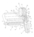
- a first linear motion unit 4 and a second linear motion unit 5 each have a slide carrier 6 or 7 and a first slide 10 and second slide 11 movable along a first linear motion axis 8 and a second linear motion axis 9, respectively.
- the drive of the first and second carriage 10, 11 along its first and second linear movement axis 8, 9 takes place by spindle drives whose drive motors 12 and 13 are also shown schematically in the drawing:
- the slide carrier 7 of the second linear motion unit 5 is arranged on a side surface of the column 1 which is parallel to the longitudinal direction of the machine bed, so that the second linear motion axis 9 runs vertically parallel to the work wheel axis of rotation 3.
- the slide carrier 6 of the first linear motion unit 4 is fixed by means of a cross member 14 on the second carriage 11 such that the first linear motion axis 8 of the first linear motion unit 4 is aligned in the direction of the work gear 2 and orthogonal to the second linear motion axis 9.
- the first carriage 10 carries a pivoting movement device 15 whose pivot axis 16 extends parallel to the first linear movement axis 8.
- a tool spindle 18 is supported with its rotary drive 19 such that its tool axis of rotation 20 orthogonal to the pivot axis 16 extends and this intersects.
- a substantially cylindrical machining tool which is designed as Anfastechnikmaschine 21, clamped, which has at least one cutting edge and is driven in rotation by the tool spindle 18 in a cutting direction.
- the Anfaswerkmaschine 21 is moved away by means of the first linear motion unit 4 of the work gear 2 and moved by the second linear motion unit 5 in a vertical upper processing position in which it by means of the first linear motion unit 4 to the upper end face 24 of the work gear 2 adjacent upper tooth edge 25 is delivered to effect their chamfering.
- the tool spindle 18 is pivoted by means of the pivoting movement device 15 in such a way that the radial end face of the chamfering tool 21 facing the left tooth flanks 26 points to the right tooth flanks 27 after pivoting.
- the cutting direction with respect to the workpiece 2 runs from bottom to top.
- a support not shown in the drawing, for a hobbing tool is arranged adjacent to its side facing away from the column 1. The latter is brought into machining engagement with the work gear 2 in a known manner for producing the toothing.
Landscapes
- Engineering & Computer Science (AREA)
- Mechanical Engineering (AREA)
- Gear Processing (AREA)
- Milling Processes (AREA)
Abstract
Description
Die Erfindung bezieht sich auf ein Verfahren zum Bearbeiten der zwischen jeder Stirnseite und den Zahnflanken stirnverzahnter Werkräder ausgebildeten Zahnkanten, bei dem ein eine Schneide aufweisendes und um eine Werkzeugdrehachse in einer Schneidrichtung drehend angetriebenes Bearbeitungswerkzeug dem um eine Werkraddrehachse drehend angetriebenen Werkrad nacheinander in zwei den Zahnkanten der beiden Stirnseiten zugeordneten Bearbeitungsstellungen zugestellt wird, und auf eine zur Durchführung dieses Verfahrens geeignete Vorrichtung.The invention relates to a method for machining the tooth edges formed between each end face and the tooth flanks of front-toothed work wheels, wherein a cutting tool having a cutting edge and rotationally driven about a tool axis of rotation in a cutting direction, the work gear rotationally driven about a Werkraddrehachse successively in two the tooth edges delivered to both end sides associated processing positions, and to a suitable apparatus for performing this method.
Bei einer derartigen bekannten Vorrichtung (
Der Erfindung liegt die Aufgabe zugrunde, ein Verfahren der eingangs genannten Art zu schaffen, das eine flexiblere Verfahrensführung und eine Verkürzung der Bearbeitungszeit ermöglicht, sowie eine zur Durchführung des Verfahrens geeignete Vorrichtung anzugeben.The invention has for its object to provide a method of the type mentioned, which allows a more flexible process management and shortening of the processing time, as well as to provide a device suitable for carrying out the method.
Erfindungsgemäß wird diese Aufgabe hinsichtlich des Verfahrens dadurch gelöst, daß zwischen den beiden Bearbeitungsstellungen die Werkzeugdrehachse um eine zu ihr orthogonale Schwenkachse zwischen zwei Schwenkstellungen verschwenkt wird, in denen die Schneidrichtungen in Bezug auf das Werkrad einander entgegengesetzt sind.According to the invention this object is achieved with respect to the method in that between the two machining positions, the tool rotation axis is pivoted about an orthogonal to its pivot axis between two pivot positions in which the cutting directions are opposite to each other in relation to the workpiece.
Bei dem erfindungsgemäßen Verfahren steht die Werkzeugdrehachse des Bearbeitungswerkzeuges als unabhängig verstellbare Achse zur Verfügung. Dadurch kann der Durchmesser des Bearbeitungswerkzeuges frei, insbesondere verhältnismäßig klein, gewählt werden, was Aufspannungskollisionen vermeiden hilft. Ferner sind in den beiden Schwenkstellungen bei gleichbleibender Drehrichtung des Antriebes des Bearbeitungswerkzeugs die Schneidrichtungen des Bearbeitungswerkzeuges einander entgegengesetzt, so daß in den beiden Bearbeitungsstellungen an den beiden stirnseitigen Enden der Verzahnung der Schnitt von innen nach außen erfolgen kann. Das Bearbeitungswerkzeug kann nur eine oder auch mehrere Schneiden aufweisen. Insbesondere kann das Bearbeitungswerkzeug zum Anfasen und/oder Entgraten der Zahnkanten ausgebildet sein. Weiterhin kann es durch eine geeignete Formgebung seiner Schneide/Schneiden und/oder Kinematik seiner Werkzeugdrehachse für eine einfiankige oder eine zweiflankige Bearbeitung des Werkrades ausgebildet sein. Im erstgenannten Fall werden die linke und die rechte Zahnkante einer Zahnlücke nacheinander bearbeitet, im zweitgenannten Fall gleichzeitig.In the method according to the invention, the tool rotation axis of the machining tool is available as an independently adjustable axis. As a result, the diameter of the machining tool can be selected freely, in particular relatively small, which helps prevent collision collisions. Furthermore, the cutting directions of the machining tool are opposite to each other in the two pivot positions with the same direction of rotation of the drive of the machining tool, so that in the two processing positions at the two front ends of the teeth, the cut can be done from the inside out. The machining tool may have only one or more cutting edges. In particular, the machining tool can be designed for chamfering and / or deburring the tooth edges. Furthermore, it can by a suitable shaping of its cutting / cutting and / or Kinematics of its tool axis for a einfiankige or a two-sided machining of the work gear be formed. In the former case, the left and the right tooth edge of a tooth gap are processed one after the other, in the second case at the same time.
Vorzugsweise wird bei dem erfindungsgemäßen Verfahren die Stirnverzahnung durch Wälzfräsen oder Formfräsen erzeugt. Beim Wälzfräsen kann dann bereits an einer der beiden Stirnseiten die Bearbeitung während des Wälzfräsens hauptzeitparallel ausgeführt werden. Bei der hauptzeitparallelen Verwendung des Fräswerkzeugs und des Bearbeitungswerkzeuges sind die Drehbewegungen ihrer beiden Werkzeugdrehachsen mit der Drehbewegung der Werkraddrehachse gekoppelt.In the method according to the invention, the face toothing is preferably produced by hobbing or milling. When hobbing can then be performed parallel to the main time machining on one of the two end faces, the machining during hobbing. In the main time parallel use of the milling tool and the machining tool, the rotational movements of its two tool axes of rotation are coupled to the rotational movement of the Werkraddrehachse.
Das Bearbeitungswerkzeug kann ein- oder mehrschneidig ausgeführt sein. Es kann wie ein kurzer Wälzfräser mit helikaler Steigung oder wie ein universeller Fräser ausgebildet sein. Die für den lagerichtigen Eingriff zwischen der oder den Schneiden des Bearbeitungswerkzeugs und den Zahnkanten erforderliche Synchronisierung zwischen den Drehbewegungen des Werkrades und des Bearbeitungswerkzeuges erfolgt durch eine entsprechend programmierte Steuerung. Hierfür ist in einer vorteilhaften Ausführungsform vorgesehen, daß zunächst an einem Exemplar eines Werkrades die Stirnverzahnung fertiggestellt und die Steuerung der Dreh- und Zustellbewegungen des Bearbeitungswerkzeuges in Abhängigkeit von der Drehstellung des Werkrades durch ein Teach-in-Verfahren programmiert wird. Beispielsweise wird hierfür das Bearbeitungswerkzeug manuell in eine Verzahnungslücke des fertig verzahnten Werkrades eingefahren und die linke und rechte Zahnflanke abgetastet. Auf ähnliche Weise wird die durch die Drehstellung des Bearbeitungswerkzeuges bestimmte Lage seiner Schneide in Bezug auf die Stirnseite des Werkrades erfaßt. Durch die Übernahme dieser Erfassungsdaten in die Steuerung wird letztere für die konkrete Bearbeitungsaufgabe programmiert.The machining tool can be designed with one or more cutting edges. It can be designed as a short hob with a helical pitch or as a universal cutter. The synchronization between the rotational movements of the work wheel and of the machining tool required for the correct engagement between the cutting edge or edges of the machining tool and the tooth edges is effected by a correspondingly programmed control. For this purpose, it is provided in an advantageous embodiment that the spur toothing is first completed on a copy of a work gear and the control of the rotational and Zustellbewegungen of the machining tool in response to the rotational position of the work gear by a teach-in procedure is programmed. For example, for this purpose, the machining tool is manually retracted into a tooth gap of the finished toothed wheel and scanned the left and right tooth flank. Similarly, the determined by the rotational position of the machining tool position of its cutting edge is detected with respect to the end face of the work wheel. By transferring this acquisition data to the controller, the latter is programmed for the specific processing task.
Eine zur Durchführung des erfindungsgemäßen Verfahrens geeignete Vorrichtung zum Bearbeiten der zwischen jeder Stirnseite und den Zahnflanken stirnverzahnter Werkräder ausgebildeten Zahnkanten, mit einer um eine Werkraddrehachse drehend antreibbaren Werkradaufnahme, auf der das Werkrad aufspannbar ist, einer um eine Werkzeugdrehachse drehend antreibbaren Werkzeugspindel, auf der ein eine Schneide aufweisendes Bearbeitungswerkzeug zur Drehung in einer Schneidrichtung aufspannbar ist, einer eine erste Linearbewegungsachse aufweisenden ersten Linearbewegungseinheit, durch die das Bearbeitungswerkzeug dem Werkrad zustellbar ist, und einer eine zweite Linearbewegungsachse aufweisenden zweiten Linearbewegungseinheit, durch die das BearbeitungsWerkzeug zwischen zwei den Zahnkanten der beiden Stirnseiten zugeordneten Bearbeitungsstellungen verstellbar ist, zeichnet sich erfindungsgemäß dadurch aus, daß eine eine zur Werkzeugdrehachse orthogonale Schwenkachse aufweisende Schwenkbewegungseinrichtung vorgesehen ist, durch die zwischen den beiden Bearbeitungssteilungen die Werkzeugdrehachse zwischen zwei Schwenkstellungen verschwenkbar ist, in denen die Schneidrichtungen in Bezug auf das Werkrad einander entgegengesetzt sind.A device suitable for carrying out the method according to the invention for processing the toothed edges formed between each end face and the tooth flanks toothed wheels, with an about a Werkraddrehachse rotationally driven Werkradaufnahme on which the work is clamped, one about a tool rotation axis rotatably driven tool spindle, on a a Cutting tool having for rotation in a cutting direction can be clamped, a first linear movement axis having a first linear motion unit, by which the machining tool is deliverable to the workwheel, and a second linear motion axis having second linear motion unit, through which the machining tool is adjustable between two the tooth edges of the two end faces associated processing positions, according to the invention characterized in that an orthogonal to the tool axis of rotation pivot axis having pivoting means is provided, between the two machining pitches the tool rotation axis between two pivot positions is pivotable, in which the cutting directions in relation on the work gear are opposed to each other.
Durch diese Verschwenkbarkeit der Werkzeugdrehachse wird erreicht, daß bei gleichbleibender Drehrichtung des Antriebs der Werkzeugspindel die Schneidrichtungen des Bearbeitungswerkzeugs in den beiden Schwenkstellungen bezüglich des Werkrades zueinander gegenläufig sind. Daher werden die Fasen an den beiden einander entgegengesetzten Enden der Verzahnung in zueinander entgegengesetzten Richtungen geschnitten, beispielsweise in Richtungen, die von der axialen Mitte der Verzahnung zu den beiden Stirnseiten hin gerichtet sind, also von innen nach außen. Hierzu ist nur ein einziges Bearbeitungswerkzeug erforderlich. Dieses kann nur eine oder auch mehrere Schneiden aufweisen. Insbesondere kann das Bearbeitungswerkzeug als Anfas- und/oder Entgratwerkzeug ausgebildet sein.By this pivoting of the tool axis of rotation is achieved that with the same direction of rotation of the drive of the tool spindle, the cutting directions of the machining tool in the two pivot positions with respect to the work gear are opposite to each other. Therefore, the chamfers are cut at the two opposite ends of the teeth in mutually opposite directions, for example, in directions which are directed from the axial center of the toothing to the two end faces, ie from the inside to the outside. For this purpose, only a single machining tool is required. This can have only one or more cutting edges. In particular, the machining tool can be configured as a chamfering and / or deburring tool.
Vorzugsweise ist die erfindungsgemäße Vorrichtung derart ausgebildet, daß in einem gegenüber einem von der Werkzeugspindel eingenommenen Raumbereich in der Umlaufrichtung der Werkraddrehachse versetzten Raumbereich ein mit dem Werkrad wälzend in Eingriff bringbares Wälzfräswerkzeug angeordnet ist, durch das die Stirnverzahnung des Werkrades herstellbar ist. Das Bearbeitungswerkzeug ist dabei von dem Wälzfräswerkzeug völlig unabhängig. Beispielsweise kann der Durchmesser des ersteren kleiner als der Durchmesser des letzteren gewählt werden, um Aufspannungskoilisionen zu vermeiden. Auch ist keine Ausrichtung des Bearbeitungswerkzeugs zum Wälzfräswerkzeug erforderlich. Insbesondere tritt keine Verringerung der spannbaren Länge des Wälzfräswerkzeugs ein. Schließlich kann hauptzeitparallel das Bearbeiten, beispielsweise Entgraten und/oder Anfasen, an einem der beiden stirnseitigen Verzahnungsenden durchgeführt werden, während sich das Wätzfräswerkzeug mit dem Werkrad im Bearbeitungseingriff befindet.Preferably, the device according to the invention is designed such that in a space occupied by the tool spindle space in the direction of rotation of the Werkraddrehachse offset space a rolling gear with the work gear engageable Wälzfräswerkzeug is arranged through which the spur gear teeth of the work gear can be produced. The machining tool is completely independent of the hobbing tool. For example, the diameter of the former may be chosen to be smaller than the diameter of the latter in order to avoid tension co-alignments. Also, no alignment of the machining tool for Wälzfräswerkzeug is required. In particular, no reduction of the tensionable length of the Wälzfräswerkzeugs occurs. Finally, parallel to the machining time, for example deburring and / or chamfering, can be performed on one of the two end-side toothing ends, while the milling cutter tool is in machining engagement with the work gear.
Weitere vorteilhafte Ausgestaltungen der Vorrichtung sind in den abhängigen Ansprüchen 9 bis 15 angegeben.Further advantageous embodiments of the device are specified in the
Nachstehend wird die Erfindung anhand eines Ausführungsbeispiels unter Bezugnahme auf die Zeichnung näher erläutert.The invention will be explained in more detail with reference to an embodiment with reference to the drawing.
Auf einem in der Zeichnung nicht dargestellten, horizontalen Maschinenbett sind in dessen Längsrichtung nebeneinander eine ebenfalls nicht dargestellte Werkradaufnahme und eine sich in ihrer Längsrichtung vertikal erstreckende Säule 1 abgestützt. Auf der Werkradaufnahme ist ein mit einer Stirnverzahnung zu versehendes Werkrad 2 um eine vertikale Werkraddrehachse 3 drehend aufspannbar. Der hierfür erforderliche Drehantrieb der Werkradaufnahme ist ebenfalls nicht dargestellt. Die vorstehend als nicht dargestellt bezeichneten Teile können in einer Weise ausgebildet sein, wie sie dem Fachmann von herkömmlichen Wfälzfräsmaschinen bekannt ist.On a horizontal machine bed, not shown in the drawing, a Werkradaufnahme also not shown and a vertically extending in its
Eine erste Linearbewegungseinheit 4 und eine zweite Linearbewegunaseinheit 5 weisen jeweils einen Schlittenträger 6 bzw. 7 und einen daran längs einer ersten Linearbewegungsachse 8 bzw. einer zweiten Linearbewegungsachse 9 bewegbaren ersten Schlitten 10 bzw. zweiten Schlitten 11 auf. Der Antrieb des ersten und zweiten Schlittens 10, 11 längs seiner ersten bzw. zweiten Linearbewegungsachse 8, 9 erfolgt durch Spindeltriebe, deren Antriebsmotore 12 bzw. 13 in der Zeichnung ebenfalls schematisch dargestellt sind:A first linear motion unit 4 and a second linear motion unit 5 each have a slide carrier 6 or 7 and a
Der Schlittenträger 7 der zweiten Linearbewegungseinheit 5 ist an einer zur Längsrichtung des Maschinenbettes parallelen Seitenfläche der Säule 1 angeordnet, so daß die zweite Linearbewegungsachse 9 parallel zur Werkraddrehachse 3 vertikal verläuft. Der Schlittenträger 6 der ersten Linearbewegungseinheit 4 ist mittels eines Querträgers 14 an dem zweiten Schlitten 11 derart festgelegt, daß die erste Linearbewegungsachse 8 der ersten Linearbewegungseinheit 4 in Richtung auf das Werkrad 2 ausgerichtet ist und orthogonal zur zweiten Linearbewegungsachse 9 verläuft.The slide carrier 7 of the second linear motion unit 5 is arranged on a side surface of the
Der erste Schlitten 10 trägt eine Schwenkbewegungseinrichtung 15, deren Schwenkachse 16 parallel zur ersten Linearbewegungsachse 8 verläuft. Auf einem um diese Schwenkachse 16 drehbaren Schwenkkopf 17 der Schwenkbewegungseinrichtung 15 ist eine Werkzeugspindel 18 mit ihrem Drehantrieb 19 derart abgestützt, daß sich ihre Werkzeugdrehachse 20 orthogonal zur Schwenkachse 16 erstreckt und diese schneidet.The
Auf der Werkzeugspindel 18 ist ein im wesentlichen zylinderförmiges Bearbeitungswerkzeug, das als Anfaswerkzeug 21 ausgebildet ist, aufgespannt, das mindestens eine Schneide aufweist und von der Werkzeugspindel 18 in einer Schneidrichtung drehend angetrieben wird.On the
In dem in der Zeichnung dargestellten Zustand ist das Anfaswerkzeug 21 mittels der zweiten Linearbevvegungseinheit 9 in eine vertikal untere Bearbeitungsstellung verfahren worden und wird in dieser Stellung mittels der ersten Linearbewegungseinheit 8 dem Werkrad 2 derart radial zugestellt, daß es mit dessen an die untere Stirnseite 22 des Werkrades 2 angrenzenden Zahnkanten 23 in einen Bearbeitungseingriff gelangt, durch den dort eine Fase erzeugt wird. Dabei verläuft die Schneidrichtung in Bezug auf das Werkrad 2 von oben nach unten. Nachdem das Anfasen der unteren Zahnkanten 23 erfolg ist, wird das Anfaswerkzeug 21 mittels der ersten Linearbewegungseinheit 4 von dem Werkrad 2 abgerückt und mittels der zweiten Linearbewegungseinheit 5 in eine vertikal obere Bearbeitungsstellung verfahren, in der es mittels der ersten Linearbewegungseinheit 4 den an die obere Stirnseite 24 des Werkrades 2 angrenzenden oberen Zahnkanten 25 zugestellt wird, um deren Anfasung zu bewirken. Bevor diese Zustellung erfolgt, wird jedoch die Werkzeugspindel 18 mittels der Schwenkbewegungseinrichtung 15 derart verschwenkt, daß die zu den linken Zahnflanken 26 weisende radiale Stirnseite des Anfaswerkzeuges 21 nach der Verschwenkung zu den rechten Zahnflanken 27 weist. Dadurch verläuft die Schneidrichtung in Bezug auf das Werkrad 2 von unten nach oben.In the state shown in the drawing, the Anfaswerkzeug 21 is moved by means of the second Linearbevvegungseinheit 9 in a vertically lower processing position has been and in this position by means of the first linear motion unit 8 the
In der Längsrichtung des Maschinenbettes neben dem Werkrad 2 ist benachbart zu seiner der Säule 1 abgewandten Seite ein in der Zeichnung nicht dargestellter Träger für ein Wälzfräswerkzeug angeordnet. Letzteres wird mit dem Werkrad 2 in bekannter Weise zur Herstellung der Verzahnung in Bearbeitungseingriff gebracht.In the longitudinal direction of the machine bed next to the
Verzeichnis der BezugszeichenList of reference numbers
- 11
- Säulepillar
- 22
- Werkradwork wheel
- 33
- WerkraddrehachseWerkraddrehachse
- 44
- erste Linearbewegungseinheitfirst linear motion unit
- 55
- zweite Linearbewegungseinheitsecond linear motion unit
- 6, 76, 7
- Schlittenträgercarriage support
- 8,98.9
- LinearbewegungsachsenLinear motion axes
- 10,1110.11
- Schlittencarriage
- 12,1312.13
- Antriebsmotoredrive motors
- 1414
- Querträgercrossbeam
- 1515
- SchwenkbewegungseinrichtungSwivel movement device
- 1616
- Schwenkachseswivel axis
- 1717
- Schwenkkopfswivel head
- 1818
- Werkzeugspindeltool spindle
- 1919
- Drehantriebrotary drive
- 2020
- WerkzeugdrehachseTool rotation axis
- 2121
- Anfaswerkzeugchamfering tool
- 2222
- untere Stirnseitelower front side
- 2323
- Zahnkantentooth edges
- 2424
- obere Stirnseiteupper end side
- 2525
- obere Zahnkantenupper tooth edges
- 2626
- linke Zahnflankenleft tooth flanks
- 2727
- rechte Zahnflankeright tooth flank
Claims (15)
Applications Claiming Priority (1)
| Application Number | Priority Date | Filing Date | Title |
|---|---|---|---|
| DE102009019433A DE102009019433A1 (en) | 2009-04-29 | 2009-04-29 | Method and device for machining the tooth edges of spur-toothed work wheels |
Publications (2)
| Publication Number | Publication Date |
|---|---|
| EP2246138A1 true EP2246138A1 (en) | 2010-11-03 |
| EP2246138B1 EP2246138B1 (en) | 2012-03-21 |
Family
ID=42352501
Family Applications (1)
| Application Number | Title | Priority Date | Filing Date |
|---|---|---|---|
| EP10002012A Active EP2246138B1 (en) | 2009-04-29 | 2010-02-26 | Method and device for processing the cog edges of machining wheels with frontal cogs |
Country Status (7)
| Country | Link |
|---|---|
| US (1) | US8769820B2 (en) |
| EP (1) | EP2246138B1 (en) |
| JP (1) | JP2010260171A (en) |
| KR (1) | KR101718330B1 (en) |
| CN (1) | CN101875140B (en) |
| AT (1) | ATE550126T1 (en) |
| DE (1) | DE102009019433A1 (en) |
Cited By (2)
| Publication number | Priority date | Publication date | Assignee | Title |
|---|---|---|---|---|
| EP3027345B1 (en) | 2013-07-31 | 2017-11-08 | Gleason-Pfauter Maschinenfabrik GmbH | Method for machining tooth edges and machining station designed for this purpose |
| US10226830B2 (en) | 2014-09-10 | 2019-03-12 | Felsomat Gmbh & Co. Kg | Method for skiving machining of a workpiece for production of a chamfer |
Families Citing this family (17)
| Publication number | Priority date | Publication date | Assignee | Title |
|---|---|---|---|---|
| DE102011118312A1 (en) | 2011-11-11 | 2013-05-16 | Liebherr-Verzahntechnik Gmbh | Method and device for processing tooth edges |
| DE102013003288A1 (en) * | 2013-02-26 | 2014-08-28 | Gleason-Pfauter Maschinenfabrik Gmbh | Method for machining or machining an internal toothing, movement changing device and machine tool |
| DE102013003804B4 (en) | 2013-03-05 | 2015-02-26 | Emag Holding Gmbh | Method and device for deburring and chamfering toothed workpieces |
| DE102014014132A1 (en) | 2014-09-30 | 2016-05-25 | Liebherr-Verzahntechnik Gmbh | Method and device for chamfering and deburring toothed workpieces |
| DE102014018328B4 (en) | 2014-12-10 | 2023-03-02 | Gleason-Pfauter Maschinenfabrik Gmbh | METHOD OF MACHINING A GEAR, TOOL ASSEMBLY AND GEAR MACHINE |
| DE102015013497A1 (en) | 2015-10-16 | 2017-04-20 | Gleason-Pfauter Maschinenfabrik Gmbh | METHOD FOR PROCESSING A BRAKING AND ARRANGEMENT THEREFOR |
| DE102015121821A1 (en) * | 2015-12-15 | 2017-06-22 | Profilator Gmbh & Co. Kg | Device and method for producing a chamfer on a toothed wheel |
| DE102016004112A1 (en) | 2016-04-05 | 2017-10-05 | Gleason-Pfauter Maschinenfabrik Gmbh | METHOD FOR PRODUCING A DEPOSITION ON A TOOTHED EDGE AND DEVICE DESIGNATED THEREFOR |
| DE102017112450A1 (en) | 2017-06-06 | 2018-12-06 | Liebherr-Verzahntechnik Gmbh | Apparatus and method for chamfering an internally toothed workpiece |
| DE102017112416A1 (en) | 2017-06-06 | 2018-12-06 | Liebherr-Verzahntechnik Gmbh | Apparatus and method for chamfering an internally toothed workpiece |
| CN107717136A (en) * | 2017-09-30 | 2018-02-23 | 广东星光传动股份有限公司 | A kind of gear chamfering device |
| CN108296573B (en) * | 2018-01-26 | 2020-01-21 | 宁波海蔓汽车科技有限公司 | Automobile gear periphery grinding device |
| WO2019226503A1 (en) | 2018-05-25 | 2019-11-28 | The Gleason Works | Multi-tool chamfering device for toothed workpieces |
| CN110936163B (en) * | 2019-10-10 | 2021-04-27 | 淄博格尔齿轮有限公司 | Cogging method for machining gear by numerical control machine tool |
| DE102020001428A1 (en) | 2020-03-05 | 2021-09-09 | Gleason-Pfauter Maschinenfabrik Gmbh | Process for tooth edge processing |
| CN111761448B (en) * | 2020-06-28 | 2021-05-04 | 浙江三欢齿轮有限公司 | Gear hobbing machine |
| DE102021002704A1 (en) | 2021-05-25 | 2021-07-29 | Gleason-Pfauter Maschinenfabrik Gmbh | PROCEDURES FOR GEAR MACHINING, IN PARTICULAR FOR TOOTH EDGE MACHINING |
Citations (2)
| Publication number | Priority date | Publication date | Assignee | Title |
|---|---|---|---|---|
| EP0282046A2 (en) * | 1987-03-10 | 1988-09-14 | Liebherr-Verzahntechnik GmbH | Machine tool for finishing the tooth flanks of roughly cut gears |
| DE4328801A1 (en) * | 1993-08-27 | 1995-03-02 | Praewema Werkzeugmaschinenfabr | Modular-construction machine tool |
Family Cites Families (13)
| Publication number | Priority date | Publication date | Assignee | Title |
|---|---|---|---|---|
| US2451447A (en) * | 1942-02-13 | 1948-10-12 | Barber Colman Co | Hobbing machine |
| JPS6376420U (en) * | 1986-11-05 | 1988-05-20 | ||
| JP3017503B2 (en) * | 1989-04-28 | 2000-03-13 | トヨタ自動車株式会社 | Universal gear chamfering machine |
| JP2641303B2 (en) * | 1989-09-20 | 1997-08-13 | 新キャタピラー三菱株式会社 | Gear tooth shaping device |
| DE4323935C1 (en) * | 1993-07-16 | 1994-10-06 | Hurth Maschinen Werkzeuge | Machine for the fine machining of tooth flanks of gear-shaped workpieces with an internally toothed tool |
| DE19639081C2 (en) * | 1996-09-24 | 2003-06-18 | Herzing & Schroth Gmbh & Co Kg | Device for producing a workpiece with a cylindrical profiled wall |
| DE19907363A1 (en) * | 1999-02-20 | 2000-08-24 | Reishauer Ag | Topological profiling process for continuous tooth grinding worms, involving using tool with required topology in distorted form on simple basic geometry |
| JP2002254244A (en) * | 2001-03-02 | 2002-09-10 | Yutaka Seimitsu Kogyo Ltd | Deburring tool, deburring method and device for umbrella-shaped gear wheel |
| DE10230148C5 (en) * | 2002-07-04 | 2015-10-22 | Liebherr-Verzahntechnik Gmbh | Method for machining gears produced by hobbing |
| DE10249039B4 (en) * | 2002-10-22 | 2005-09-01 | Wera-Werk Hermann Werner Gmbh & Co. Kg | Device for gear cutting and reworking of workpieces |
| DE10330474B4 (en) | 2003-07-05 | 2009-03-05 | Fette Gmbh | Device for producing a gear from a gear blank |
| DE10342495B4 (en) * | 2003-09-12 | 2017-02-02 | Reishauer Ag | Method and device for centering of pre-toothed workpieces on gear finishing machines |
| DE102005054237A1 (en) * | 2005-11-14 | 2007-05-16 | Weigl Engineering Gmbh | Production process for top surfaces and chamfers of gear wheels involves having at least one of axes of rotation able to be turned against other |
-
2009
- 2009-04-29 DE DE102009019433A patent/DE102009019433A1/en active Pending
-
2010
- 2010-02-26 AT AT10002012T patent/ATE550126T1/en active
- 2010-02-26 EP EP10002012A patent/EP2246138B1/en active Active
- 2010-04-08 US US12/756,402 patent/US8769820B2/en active Active
- 2010-04-13 KR KR1020100033758A patent/KR101718330B1/en active IP Right Grant
- 2010-04-28 CN CN2010101744754A patent/CN101875140B/en active Active
- 2010-04-28 JP JP2010102834A patent/JP2010260171A/en active Pending
Patent Citations (2)
| Publication number | Priority date | Publication date | Assignee | Title |
|---|---|---|---|---|
| EP0282046A2 (en) * | 1987-03-10 | 1988-09-14 | Liebherr-Verzahntechnik GmbH | Machine tool for finishing the tooth flanks of roughly cut gears |
| DE4328801A1 (en) * | 1993-08-27 | 1995-03-02 | Praewema Werkzeugmaschinenfabr | Modular-construction machine tool |
Cited By (3)
| Publication number | Priority date | Publication date | Assignee | Title |
|---|---|---|---|---|
| EP3027345B1 (en) | 2013-07-31 | 2017-11-08 | Gleason-Pfauter Maschinenfabrik GmbH | Method for machining tooth edges and machining station designed for this purpose |
| EP3027345B2 (en) † | 2013-07-31 | 2023-12-13 | Gleason-Pfauter Maschinenfabrik GmbH | Method for machining tooth edges and machining station designed for this purpose |
| US10226830B2 (en) | 2014-09-10 | 2019-03-12 | Felsomat Gmbh & Co. Kg | Method for skiving machining of a workpiece for production of a chamfer |
Also Published As
| Publication number | Publication date |
|---|---|
| JP2010260171A (en) | 2010-11-18 |
| ATE550126T1 (en) | 2012-04-15 |
| DE102009019433A1 (en) | 2010-11-04 |
| CN101875140B (en) | 2013-11-27 |
| EP2246138B1 (en) | 2012-03-21 |
| KR101718330B1 (en) | 2017-03-21 |
| US20100278605A1 (en) | 2010-11-04 |
| US8769820B2 (en) | 2014-07-08 |
| CN101875140A (en) | 2010-11-03 |
| KR20100118940A (en) | 2010-11-08 |
Similar Documents
| Publication | Publication Date | Title |
|---|---|---|
| EP2246138B1 (en) | Method and device for processing the cog edges of machining wheels with frontal cogs | |
| EP2385885B2 (en) | Device and method for cutting teeth in workpieces | |
| EP2364231B1 (en) | Hob peeling method and use | |
| EP3271100B1 (en) | Tooth-forming method having tooth finishing, and combination tool therefor | |
| EP2732895B1 (en) | Machine tool for manufacturing profiles | |
| EP3546101B1 (en) | Method and device for gear cutting work wheels by means of gear skiving | |
| EP3388179A1 (en) | Method for machining the teeth of a workpiece | |
| EP2786824A2 (en) | Device and method for chamfering a workpiece | |
| EP3552743B1 (en) | Device and method for chamfering a toothed workpiece | |
| EP2271455A1 (en) | Machining head | |
| EP3061554A1 (en) | Processing head for a gear cutting machine and method for gear cutting a workpiece, in particular a worm shaft or gear rack | |
| EP2505291A2 (en) | Gear cutting machine | |
| DE102011110911A1 (en) | Milling machine for milling work pieces, particularly gears, has rotary mounted machine table, which has two work piece spindles, where processing unit is provided for milling work piece clamped in former work piece spindle | |
| DE10230148B4 (en) | Method for machining gears produced by hobbing | |
| DE102013003964A1 (en) | Gear cutting machine with double machining head | |
| DE102007039959B4 (en) | Method for cold rolling of longitudinal gears and profiles for long shaft-shaped workpieces and profile rolling machine for this purpose | |
| WO2014206902A1 (en) | Hobbing machine having a pivoting arm, on which a chamfering device and at least one cutting tool are arranged | |
| EP3386670A1 (en) | Method for creating or machining gears and gear-cutting machine designed therefor | |
| EP0453875B1 (en) | Machine for metal cutting | |
| DE10127973C2 (en) | Device for milling locking grooves and switching stops on the tooth flanks of individual teeth of sliding sleeves for manual transmissions | |
| DE1966960B2 (en) | Hobbing device as an additional device for automatic lathes | |
| EP3013506B1 (en) | Hobbing machine comprising a hobber head and two chamfering devices on a common carriage | |
| WO1995019239A1 (en) | Miller for machining crest edges of the faces of the teeth of a toothed wheel | |
| EP2754517B1 (en) | Machining tool for a multi-spindle machine tool and machine tool with same | |
| DE1284257B (en) | Device for machining and thread cutting on pipe ends |
Legal Events
| Date | Code | Title | Description |
|---|---|---|---|
| PUAI | Public reference made under article 153(3) epc to a published international application that has entered the european phase |
Free format text: ORIGINAL CODE: 0009012 |
|
| 17P | Request for examination filed |
Effective date: 20100226 |
|
| AK | Designated contracting states |
Kind code of ref document: A1 Designated state(s): AT BE BG CH CY CZ DE DK EE ES FI FR GB GR HR HU IE IS IT LI LT LU LV MC MK MT NL NO PL PT RO SE SI SK SM TR |
|
| AX | Request for extension of the european patent |
Extension state: AL BA RS |
|
| GRAP | Despatch of communication of intention to grant a patent |
Free format text: ORIGINAL CODE: EPIDOSNIGR1 |
|
| RIC1 | Information provided on ipc code assigned before grant |
Ipc: B23F 19/10 20060101AFI20110830BHEP |
|
| GRAS | Grant fee paid |
Free format text: ORIGINAL CODE: EPIDOSNIGR3 |
|
| GRAA | (expected) grant |
Free format text: ORIGINAL CODE: 0009210 |
|
| AK | Designated contracting states |
Kind code of ref document: B1 Designated state(s): AT BE BG CH CY CZ DE DK EE ES FI FR GB GR HR HU IE IS IT LI LT LU LV MC MK MT NL NO PL PT RO SE SI SK SM TR |
|
| REG | Reference to a national code |
Ref country code: GB Ref legal event code: FG4D Free format text: NOT ENGLISH |
|
| REG | Reference to a national code |
Ref country code: CH Ref legal event code: EP |
|
| REG | Reference to a national code |
Ref country code: IE Ref legal event code: FG4D Free format text: LANGUAGE OF EP DOCUMENT: GERMAN |
|
| REG | Reference to a national code |
Ref country code: CH Ref legal event code: NV Representative=s name: WERNER FENNER PATENTANWALT |
|
| REG | Reference to a national code |
Ref country code: AT Ref legal event code: REF Ref document number: 550126 Country of ref document: AT Kind code of ref document: T Effective date: 20120415 |
|
| REG | Reference to a national code |
Ref country code: DE Ref legal event code: R096 Ref document number: 502010000526 Country of ref document: DE Effective date: 20120516 |
|
| REG | Reference to a national code |
Ref country code: NL Ref legal event code: VDEP Effective date: 20120321 |
|
| PG25 | Lapsed in a contracting state [announced via postgrant information from national office to epo] |
Ref country code: NO Free format text: LAPSE BECAUSE OF FAILURE TO SUBMIT A TRANSLATION OF THE DESCRIPTION OR TO PAY THE FEE WITHIN THE PRESCRIBED TIME-LIMIT Effective date: 20120621 Ref country code: HR Free format text: LAPSE BECAUSE OF FAILURE TO SUBMIT A TRANSLATION OF THE DESCRIPTION OR TO PAY THE FEE WITHIN THE PRESCRIBED TIME-LIMIT Effective date: 20120321 Ref country code: LT Free format text: LAPSE BECAUSE OF FAILURE TO SUBMIT A TRANSLATION OF THE DESCRIPTION OR TO PAY THE FEE WITHIN THE PRESCRIBED TIME-LIMIT Effective date: 20120321 |
|
| LTIE | Lt: invalidation of european patent or patent extension |
Effective date: 20120321 |
|
| PG25 | Lapsed in a contracting state [announced via postgrant information from national office to epo] |
Ref country code: GR Free format text: LAPSE BECAUSE OF FAILURE TO SUBMIT A TRANSLATION OF THE DESCRIPTION OR TO PAY THE FEE WITHIN THE PRESCRIBED TIME-LIMIT Effective date: 20120622 Ref country code: FI Free format text: LAPSE BECAUSE OF FAILURE TO SUBMIT A TRANSLATION OF THE DESCRIPTION OR TO PAY THE FEE WITHIN THE PRESCRIBED TIME-LIMIT Effective date: 20120321 Ref country code: LV Free format text: LAPSE BECAUSE OF FAILURE TO SUBMIT A TRANSLATION OF THE DESCRIPTION OR TO PAY THE FEE WITHIN THE PRESCRIBED TIME-LIMIT Effective date: 20120321 |
|
| PG25 | Lapsed in a contracting state [announced via postgrant information from national office to epo] |
Ref country code: CY Free format text: LAPSE BECAUSE OF FAILURE TO SUBMIT A TRANSLATION OF THE DESCRIPTION OR TO PAY THE FEE WITHIN THE PRESCRIBED TIME-LIMIT Effective date: 20120321 |
|
| PG25 | Lapsed in a contracting state [announced via postgrant information from national office to epo] |
Ref country code: SI Free format text: LAPSE BECAUSE OF FAILURE TO SUBMIT A TRANSLATION OF THE DESCRIPTION OR TO PAY THE FEE WITHIN THE PRESCRIBED TIME-LIMIT Effective date: 20120321 Ref country code: RO Free format text: LAPSE BECAUSE OF FAILURE TO SUBMIT A TRANSLATION OF THE DESCRIPTION OR TO PAY THE FEE WITHIN THE PRESCRIBED TIME-LIMIT Effective date: 20120321 Ref country code: EE Free format text: LAPSE BECAUSE OF FAILURE TO SUBMIT A TRANSLATION OF THE DESCRIPTION OR TO PAY THE FEE WITHIN THE PRESCRIBED TIME-LIMIT Effective date: 20120321 Ref country code: SE Free format text: LAPSE BECAUSE OF FAILURE TO SUBMIT A TRANSLATION OF THE DESCRIPTION OR TO PAY THE FEE WITHIN THE PRESCRIBED TIME-LIMIT Effective date: 20120321 Ref country code: IS Free format text: LAPSE BECAUSE OF FAILURE TO SUBMIT A TRANSLATION OF THE DESCRIPTION OR TO PAY THE FEE WITHIN THE PRESCRIBED TIME-LIMIT Effective date: 20120721 Ref country code: CZ Free format text: LAPSE BECAUSE OF FAILURE TO SUBMIT A TRANSLATION OF THE DESCRIPTION OR TO PAY THE FEE WITHIN THE PRESCRIBED TIME-LIMIT Effective date: 20120321 Ref country code: PL Free format text: LAPSE BECAUSE OF FAILURE TO SUBMIT A TRANSLATION OF THE DESCRIPTION OR TO PAY THE FEE WITHIN THE PRESCRIBED TIME-LIMIT Effective date: 20120321 |
|
| PG25 | Lapsed in a contracting state [announced via postgrant information from national office to epo] |
Ref country code: PT Free format text: LAPSE BECAUSE OF FAILURE TO SUBMIT A TRANSLATION OF THE DESCRIPTION OR TO PAY THE FEE WITHIN THE PRESCRIBED TIME-LIMIT Effective date: 20120723 Ref country code: SK Free format text: LAPSE BECAUSE OF FAILURE TO SUBMIT A TRANSLATION OF THE DESCRIPTION OR TO PAY THE FEE WITHIN THE PRESCRIBED TIME-LIMIT Effective date: 20120321 |
|
| PLBE | No opposition filed within time limit |
Free format text: ORIGINAL CODE: 0009261 |
|
| STAA | Information on the status of an ep patent application or granted ep patent |
Free format text: STATUS: NO OPPOSITION FILED WITHIN TIME LIMIT |
|
| PG25 | Lapsed in a contracting state [announced via postgrant information from national office to epo] |
Ref country code: DK Free format text: LAPSE BECAUSE OF FAILURE TO SUBMIT A TRANSLATION OF THE DESCRIPTION OR TO PAY THE FEE WITHIN THE PRESCRIBED TIME-LIMIT Effective date: 20120321 Ref country code: NL Free format text: LAPSE BECAUSE OF FAILURE TO SUBMIT A TRANSLATION OF THE DESCRIPTION OR TO PAY THE FEE WITHIN THE PRESCRIBED TIME-LIMIT Effective date: 20120321 |
|
| 26N | No opposition filed |
Effective date: 20130102 |
|
| REG | Reference to a national code |
Ref country code: DE Ref legal event code: R097 Ref document number: 502010000526 Country of ref document: DE Effective date: 20130102 |
|
| PG25 | Lapsed in a contracting state [announced via postgrant information from national office to epo] |
Ref country code: ES Free format text: LAPSE BECAUSE OF FAILURE TO SUBMIT A TRANSLATION OF THE DESCRIPTION OR TO PAY THE FEE WITHIN THE PRESCRIBED TIME-LIMIT Effective date: 20120702 |
|
| PG25 | Lapsed in a contracting state [announced via postgrant information from national office to epo] |
Ref country code: BG Free format text: LAPSE BECAUSE OF FAILURE TO SUBMIT A TRANSLATION OF THE DESCRIPTION OR TO PAY THE FEE WITHIN THE PRESCRIBED TIME-LIMIT Effective date: 20120621 |
|
| BERE | Be: lapsed |
Owner name: GLEASON-PFAUTER, MASCHINENFABRIK G.M.B.H. Effective date: 20130228 |
|
| PG25 | Lapsed in a contracting state [announced via postgrant information from national office to epo] |
Ref country code: MC Free format text: LAPSE BECAUSE OF NON-PAYMENT OF DUE FEES Effective date: 20130228 |
|
| REG | Reference to a national code |
Ref country code: FR Ref legal event code: ST Effective date: 20131031 |
|
| REG | Reference to a national code |
Ref country code: IE Ref legal event code: MM4A |
|
| PG25 | Lapsed in a contracting state [announced via postgrant information from national office to epo] |
Ref country code: FR Free format text: LAPSE BECAUSE OF NON-PAYMENT OF DUE FEES Effective date: 20130228 Ref country code: IE Free format text: LAPSE BECAUSE OF NON-PAYMENT OF DUE FEES Effective date: 20130226 Ref country code: BE Free format text: LAPSE BECAUSE OF NON-PAYMENT OF DUE FEES Effective date: 20130228 |
|
| PG25 | Lapsed in a contracting state [announced via postgrant information from national office to epo] |
Ref country code: MT Free format text: LAPSE BECAUSE OF FAILURE TO SUBMIT A TRANSLATION OF THE DESCRIPTION OR TO PAY THE FEE WITHIN THE PRESCRIBED TIME-LIMIT Effective date: 20120321 |
|
| GBPC | Gb: european patent ceased through non-payment of renewal fee |
Effective date: 20140226 |
|
| PG25 | Lapsed in a contracting state [announced via postgrant information from national office to epo] |
Ref country code: GB Free format text: LAPSE BECAUSE OF NON-PAYMENT OF DUE FEES Effective date: 20140226 |
|
| PG25 | Lapsed in a contracting state [announced via postgrant information from national office to epo] |
Ref country code: SM Free format text: LAPSE BECAUSE OF FAILURE TO SUBMIT A TRANSLATION OF THE DESCRIPTION OR TO PAY THE FEE WITHIN THE PRESCRIBED TIME-LIMIT Effective date: 20120321 |
|
| PG25 | Lapsed in a contracting state [announced via postgrant information from national office to epo] |
Ref country code: TR Free format text: LAPSE BECAUSE OF FAILURE TO SUBMIT A TRANSLATION OF THE DESCRIPTION OR TO PAY THE FEE WITHIN THE PRESCRIBED TIME-LIMIT Effective date: 20120321 |
|
| PG25 | Lapsed in a contracting state [announced via postgrant information from national office to epo] |
Ref country code: HU Free format text: LAPSE BECAUSE OF FAILURE TO SUBMIT A TRANSLATION OF THE DESCRIPTION OR TO PAY THE FEE WITHIN THE PRESCRIBED TIME-LIMIT; INVALID AB INITIO Effective date: 20100226 Ref country code: LU Free format text: LAPSE BECAUSE OF NON-PAYMENT OF DUE FEES Effective date: 20130226 Ref country code: MK Free format text: LAPSE BECAUSE OF FAILURE TO SUBMIT A TRANSLATION OF THE DESCRIPTION OR TO PAY THE FEE WITHIN THE PRESCRIBED TIME-LIMIT Effective date: 20120321 |
|
| REG | Reference to a national code |
Ref country code: AT Ref legal event code: MM01 Ref document number: 550126 Country of ref document: AT Kind code of ref document: T Effective date: 20150226 |
|
| PG25 | Lapsed in a contracting state [announced via postgrant information from national office to epo] |
Ref country code: AT Free format text: LAPSE BECAUSE OF NON-PAYMENT OF DUE FEES Effective date: 20150226 |
|
| REG | Reference to a national code |
Ref country code: CH Ref legal event code: NV Representative=s name: SERAINA FENNER, CH |
|
| PGFP | Annual fee paid to national office [announced via postgrant information from national office to epo] |
Ref country code: CH Payment date: 20230307 Year of fee payment: 14 |
|
| PGFP | Annual fee paid to national office [announced via postgrant information from national office to epo] |
Ref country code: IT Payment date: 20230221 Year of fee payment: 14 Ref country code: DE Payment date: 20230223 Year of fee payment: 14 |
|
| P01 | Opt-out of the competence of the unified patent court (upc) registered |
Effective date: 20230516 |