EP0282046A2 - Machine tool for finishing the tooth flanks of roughly cut gears - Google Patents
Machine tool for finishing the tooth flanks of roughly cut gears Download PDFInfo
- Publication number
- EP0282046A2 EP0282046A2 EP88103747A EP88103747A EP0282046A2 EP 0282046 A2 EP0282046 A2 EP 0282046A2 EP 88103747 A EP88103747 A EP 88103747A EP 88103747 A EP88103747 A EP 88103747A EP 0282046 A2 EP0282046 A2 EP 0282046A2
- Authority
- EP
- European Patent Office
- Prior art keywords
- tool
- worm
- grinding
- polishing
- workpiece
- Prior art date
- Legal status (The legal status is an assumption and is not a legal conclusion. Google has not performed a legal analysis and makes no representation as to the accuracy of the status listed.)
- Granted
Links
Images


Classifications
-
- B—PERFORMING OPERATIONS; TRANSPORTING
- B23—MACHINE TOOLS; METAL-WORKING NOT OTHERWISE PROVIDED FOR
- B23F—MAKING GEARS OR TOOTHED RACKS
- B23F21/00—Tools specially adapted for use in machines for manufacturing gear teeth
- B23F21/005—Tools specially adapted for use in machines for manufacturing gear teeth with plural tools on a common axis
-
- B—PERFORMING OPERATIONS; TRANSPORTING
- B23—MACHINE TOOLS; METAL-WORKING NOT OTHERWISE PROVIDED FOR
- B23F—MAKING GEARS OR TOOTHED RACKS
- B23F21/00—Tools specially adapted for use in machines for manufacturing gear teeth
- B23F21/02—Grinding discs; Grinding worms
- B23F21/026—Grinding worms
-
- B—PERFORMING OPERATIONS; TRANSPORTING
- B23—MACHINE TOOLS; METAL-WORKING NOT OTHERWISE PROVIDED FOR
- B23F—MAKING GEARS OR TOOTHED RACKS
- B23F21/00—Tools specially adapted for use in machines for manufacturing gear teeth
- B23F21/03—Honing tools
- B23F21/035—Honing worms
-
- B—PERFORMING OPERATIONS; TRANSPORTING
- B23—MACHINE TOOLS; METAL-WORKING NOT OTHERWISE PROVIDED FOR
- B23F—MAKING GEARS OR TOOTHED RACKS
- B23F5/00—Making straight gear teeth involving moving a tool relatively to a workpiece with a rolling-off or an enveloping motion with respect to the gear teeth to be made
- B23F5/02—Making straight gear teeth involving moving a tool relatively to a workpiece with a rolling-off or an enveloping motion with respect to the gear teeth to be made by grinding
- B23F5/04—Making straight gear teeth involving moving a tool relatively to a workpiece with a rolling-off or an enveloping motion with respect to the gear teeth to be made by grinding the tool being a grinding worm
-
- Y—GENERAL TAGGING OF NEW TECHNOLOGICAL DEVELOPMENTS; GENERAL TAGGING OF CROSS-SECTIONAL TECHNOLOGIES SPANNING OVER SEVERAL SECTIONS OF THE IPC; TECHNICAL SUBJECTS COVERED BY FORMER USPC CROSS-REFERENCE ART COLLECTIONS [XRACs] AND DIGESTS
- Y10—TECHNICAL SUBJECTS COVERED BY FORMER USPC
- Y10T—TECHNICAL SUBJECTS COVERED BY FORMER US CLASSIFICATION
- Y10T409/00—Gear cutting, milling, or planing
- Y10T409/10—Gear cutting
- Y10T409/101431—Gear tooth shape generating
- Y10T409/10159—Hobbing
Definitions
- the invention relates to a machine tool for fine machining the tooth flanks of pre-toothed gears, with a tool spindle carrying a grinding worm, which can be rotatably driven with rolling coupling with the workpiece carrier, and which is mounted in a reciprocating tool slide arrangement, by means of which the grinding worm has a working stroke and a relative to the workpiece subsequent return stroke can be issued.
- the tooth profile is created by envelope cuts, i.e. the tooth flank is not formed exactly, but is approximated in a faceted manner by a finite number of envelope cuts.
- envelope cuts i.e. the tooth flank is not formed exactly, but is approximated in a faceted manner by a finite number of envelope cuts.
- Each envelope cut of the envelope cut profile touches the theoretical involute profile at one point, all other points deviate from the involute profile.
- the feed markings that result from the axial feed of the tool overlap the envelope cut markings in the profile direction. These markings, which are oriented in the longitudinal direction of the teeth, interfere with the rolling or rolling of gear pairs and lead to undesirable noise generation.
- a number of fine machining processes such as honing or lapping, are known with which these deviations from the involute shape can be eliminated. These processes are known as processes for fine machining, which are subordinate to fine machining processes such as generating grinding or skiving. Typically, through these processes for fine machining reduce the surface roughness of the flanks of the gear wheel to below 4 micrometers.
- the grinding worms used for grinding cause a relatively large surface roughness, which moreover has an unfavorable orientation and which this leads to a relatively high level of noise.
- This problem can only be remedied either by using a smaller grit, but this reduces the performance in uninteresting areas, or by polishing or honing the gears again after grinding. Polishing is usually carried out on separate machines, the kinematics of which in turn corresponds to the known hobbing: - or hobbing machines.
- the workpieces must be clamped separately in these machines and re-synchronized. The necessary changeover and idle times add up to a value that is not acceptable in modern gear manufacturing.
- a helical tool for honing gears which consists of a soft-elastic plastic with embedded abrasive particles. Honing differs from grinding in that only the tool is driven during honing and the workpiece is carried along accordingly, whereby inevitably only one flank can be machined.
- a soft-elastic honing or polishing tool has the advantage that an improvement in the surface roughness can be achieved without having to make too high demands on the accuracy of the synchronization gears.
- An elastic tool is also able to adapt to certain desired profile deviations or to compensate for them.
- the present invention has for its object to achieve the piece times in the manufacture of ground and polished gears compared to the previously further lowering values.
- the essence of the invention consists in the use of a new type of tool in the framework of a gear grinding machine known in principle, the tool being characterized in that it has a grinding worm and a polishing worm, the tooth profile of which is essentially the same, one behind the other on one and the same tool spindle correspond and whose turns run along a common, uninterrupted helix.
- the gear wheel to be machined can come into engagement with the grinding worm and polishing worm one after the other without having to clamp and thread again.
- the functions of these two tools can be clearly separated, i.e. that no more material is removed by the polishing screw.
- the polishing screw can be made so soft that it actually only improves the surface roughness and adapts perfectly to the existing flank geometry.
- tooth profile of the polishing worm should be essentially the same as that of the grinding worm, deviations are possible, for example in order to generate an increased flank pressure between the tool and the workpiece.
- the elasticity of the polishing worm used makes it possible to improve the surface roughness of the workpiece flank without requiring additional machine movements and without having to change the flank geometry of the tool.
- the further advantage is that the theoretical point of contact between the workpiece and the tool is increased in a contact area. Within this area, there are relative movements of the abrasive material with respect to the workpiece flank, which do not have the same direction of the markings that were generated in the previous finishing. These markings or grooves can be processed practically better.
- the tool i.e. the polishing screw preferably consists of a metallic sleeve in order to enable a firm clamping on the tool spindle.
- a thermoplastic can be used as the plastic material; the abrasive can be silicon carbide, high-grade corundum or any other suitable material.
- the optimum particle size distribution and the degree of filler in the plastic matrix can be determined in simple test series depending on the application.
- the elasticity (Shore hardness) of the material must be selected so that the flanks of the tool can compensate for a roughness of the pre-machined gear wheel of approximately + -30 micrometers.
- a hard-faced master wheel as is known for dressing grinding wheels and other tools, is suitable for dressing the tool.
- the plastic material and the abrasive can preferably be coordinated with one another in such a way that a self-sharpening effect occurs.
- This dressing method has the advantage that the tool geometry is automatically adapted to the workpiece geometry without the need for a special dressing device.
- the machine on which the polishing screw is used can be, for example, an generating grinding machine shown in FIG. 1.
- Continuous generating grinding machines are equipped with a grinding worm as a tool.
- the process which is also known as gear hobbing, is identical to the known hobbing.
- the stationary workpiece table is located on the machine bed, on which a pre-toothed gearwheel is clamped with a corresponding clamping device with a vertical axis.
- the workpiece can be rotated around its vertical axis with the tool worm for coupling. The movement is symbolized by the arrow labeled 2.
- the radially displaceable main stand (the radial infeed direction is symbolized by the arrow denoted by 3) carries a tangential slide for the tangential displacement of the tool worm (this displacement direction is indicated by the arrow denoted by 5).
- the tangential slide can also be moved axially (arrow 4) and swiveled around a horizontal axis (arrow 6).
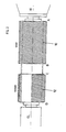
- a grinding worm 10 is firmly clamped in front of a polishing worm 12 on the tool or tangential slide on the tool spindle between the counter bearing (GL) and the main bearing (HL).
- a short distance bushing is arranged between the grinding worm and the polishing worm to ensure that one of the worms is properly extended and the other is retracted.
- the grinding worm 10 is a rigid worm with, for example, a urea coating.
- the flank geometry of the grinding worm preferably changes over its axial length in order to effect corresponding flank corrections when passing through the tooth gap.
- the polishing screw on the other hand, consists of an elastic plastic material.
- the tooth profile of the screw turns remains the same over the axial length. Otherwise, the screws correspond in terms of diameter, number of gears and pitch angle, slight deviations in diameter and pitch angle being possible.
- FIG. 3 shows the path / time diagram of the tool spindle relative to the tool.
- the three coordinate axes indicate the speed in tangential, axial and radial directions.
- the workpiece is changed and the grinding worm is threaded into a tooth gap of the pre-toothed work wheel.
- the diagonal stroke begins with a tangential and an axial speed component from A to B.
- the path covered is not exactly straight, but is slightly curved to produce a certain crowning of the tooth flanks. This curved path is indicated by a dashed line.
- Arrived at point B the tool spindle is disengaged followed by a short axial movement and a renewed radial immersion, whereby the first turns of the polishing worm come into engagement with the corresponding tooth gaps on the work wheel.
- all tooth gaps of the work wheel are applied, i.e. polished.
- the polishing worm only reduces the surface roughness.
- the method according to the invention was carried out, for example, on a gearwheel with 35 teeth, a helix angle of 33 °, a module of 2 mm and a tooth width of 14.7 mm.
- the screw diameter was 140 mm.
- the gear still had an allowance of 0.12 mm per flank.
- the speed of the tool spindle can be 10900 revolutions per minute, which results in a peripheral speed of 80 m / s.
- the speed of the workpiece table is 312 revolutions per minute.
- the path feed per workpiece revolution is 1 mm, a total of 6 seconds are required for the grinding process.
Abstract
Description
Die Erfindung betrifft eine Werkzeugmaschine zum Feinbearbeiten der Zahnflanken von vorverzahnten Zahnrädern, mit einer eine Schleifschnecke tragenden, unter Wälzkopplung mit dem Werkstückträger drehantreibbare Werkzeugspindel, die in einer hin- und herbewegbaren Werkzeugschlittenanordnung gelagert ist, mittels welcher der Schleifschnecke bezüglich des Werkstückes ein Arbeitshub und ein sich daran anschließender Rückhub erteilbar ist.The invention relates to a machine tool for fine machining the tooth flanks of pre-toothed gears, with a tool spindle carrying a grinding worm, which can be rotatably driven with rolling coupling with the workpiece carrier, and which is mounted in a reciprocating tool slide arrangement, by means of which the grinding worm has a working stroke and a relative to the workpiece subsequent return stroke can be issued.
Bei Verzahnverfahren, die im Wälzverfahren arbeiten, entsteht das Zahnprofil durch Hüllschnitte, d.h. die Zahnflanke wird nicht exakt ausgebildet, sondern durch eine endliche Anzahl von Hüllschnitten facettenartig angenähert. Jeder Hüllschnitt des Hüllschnittprofils berührt das theoretische Evolventenprofil in einem Punkt, alle übrigen Punkte weichen vom Evolventenprofil ab. Die aus dem Axialvorschub des Werkzeugs entstehenden Vorschubmarkierungen überlagern sich den Hüllschnittmarkierungen in Profilrichtung. Diese in Zahnlängsrichtung orientierten Markierungen stören beim Abrollen bzw. Abwälzen von Zahnradpaarungen und führen zu einer unerwünschten Geräuschentwicklung.In toothing processes that work in the generating process, the tooth profile is created by envelope cuts, i.e. the tooth flank is not formed exactly, but is approximated in a faceted manner by a finite number of envelope cuts. Each envelope cut of the envelope cut profile touches the theoretical involute profile at one point, all other points deviate from the involute profile. The feed markings that result from the axial feed of the tool overlap the envelope cut markings in the profile direction. These markings, which are oriented in the longitudinal direction of the teeth, interfere with the rolling or rolling of gear pairs and lead to undesirable noise generation.
Es sind eine Reihe von Feinbearbeitungsverfahren, wie beispielsweise das Honen oder Läppen bekannt, mit welchen diese Abweichungen von der Evolventenform beseitigt werden können. Man bezeichnet diese Verfahren als Verfahren zur Feinstbearbeitung, die den Feinbearbeitungsverfahren, wie dem Wälzschleifen oder Schälwälzfräsen nachgeordnet sind. In typischer Weise wird durch diese Verfahren zur Feinstbearbeitung die Oberflächenrauhigkeit der Flanken des Zahnrades auf unter 4 Mikrometer vermindert.A number of fine machining processes, such as honing or lapping, are known with which these deviations from the involute shape can be eliminated. These processes are known as processes for fine machining, which are subordinate to fine machining processes such as generating grinding or skiving. Typically, through these processes for fine machining reduce the surface roughness of the flanks of the gear wheel to below 4 micrometers.
Aus der US-PS 2,214,225 ist es bereits bekannt, zwei Schabräder mit unterschiedlichen Wirkeigenschaften auf einer gemeinsamen Spindel axial hintereinander anzuordnen, wobei das zu bearbeitende Zahnrad durch eine Axialverschiebung des Werkzeugs zunächst mit dem einen Schabrad und danach mit dem anderen Schabrad beaufschlagt wird. Um beim Umschalten einen Eingriff zwischen Werkzeug und Werkstück aufrechtzuerhalten, ist zwischen den Schabrädern ein kleineres Blindrad angeordnet, das beim Umschalten dafür sorgt, daß die Relativstellung von Werkzeug und Werkstück erhalten bleibt. Das Schaben von Zahnrädern ist ein Verfahren, das wirkungsvoll nur im ungehärteten Zustand der Zahnräder eingesetzt werden kann, wodurch Verzugsfehler beim Härten die Endqualität verschlechtern.From US Pat. No. 2,214,225 it is already known to arrange two shaving wheels with different active properties axially one behind the other on a common spindle, the toothed wheel to be machined being acted upon first by an axial displacement of the tool with one shaving wheel and then with the other shaving wheel. In order to maintain an engagement between the tool and the workpiece when switching, a smaller idler wheel is arranged between the shaving wheels, which ensures that the relative position of the tool and workpiece is maintained when switching. The scraping of gears is a process that can only be used effectively when the gears are not hardened, whereby warping errors during hardening deteriorate the final quality.
In neuerer Zeit setzt sich zur Feinbearbeitung von vorverzahnten Zahnrädern das Wälzschleifen mehr und mehr durch, bei dem nach dem Prinzip des Wälzfräsens eine Schleifschnecke auf den Zahnflanken des nachzubearbeitenden Zahnrades abgewälzt wird. Derartige Schleifmaschinen sind bekannt, eine typische Konstruktion ist unter der Bezeichnung RZ 300E in der Werbeschrift der Firma Reishauer (Kd. 1 182 200) beschrieben und dargestellt.In recent times, hobbing has become more and more common for fine machining of pre-toothed gears, in which, according to the principle of hobbing, a grinding worm is rolled on the tooth flanks of the gear to be reworked. Such grinding machines are known, a typical construction is described and shown under the designation RZ 300E in the advertising brochure of the company Reishauer (Kd. 1 182 200).
Die zum Schleifen verwendeten Schleifschnecken verursachen eine relativ große Oberflächenrauhigkeit, die überdies eine ungünstige Orientierung aufweist und die dadurch zu einer relativ hohen Geräuschentwicklung führt. Dieses Problem läßt sich nur dadurch abstellen, daß entweder ein kleineres Korn verwendet wird, wodurch aber die Leistung in uninteressante Bereiche absinkt, oder aber die Zahnräder nach dem Schleifen nochmals poliert oder gehont werden. Das Polieren erfolgt üblicherweise auf gesonderten Maschinen, deren Kinematik wiederum den bekannten Wälzfräs:- bzw. Wälzschleifmaschinen entspricht. Die Werkstücke mussen allerdings in diese Maschinen separat eingespannt und neu synchronisiert werden. Die dafür erforderlichen Umrüst- und Nebenzeiten summieren sich zu einem in der modernen Zahnradfertigung nicht akzeptablen Wert auf.The grinding worms used for grinding cause a relatively large surface roughness, which moreover has an unfavorable orientation and which this leads to a relatively high level of noise. This problem can only be remedied either by using a smaller grit, but this reduces the performance in uninteresting areas, or by polishing or honing the gears again after grinding. Polishing is usually carried out on separate machines, the kinematics of which in turn corresponds to the known hobbing: - or hobbing machines. However, the workpieces must be clamped separately in these machines and re-synchronized. The necessary changeover and idle times add up to a value that is not acceptable in modern gear manufacturing.
Aus der DOS 23 01 312 ist ein schneckenförmiges Werkzeug zum Honen von Zahnrädern bekannt, das aus einem weich-elastischen Kunststoff mit eingelagerten Schleifmittelteilchen besteht. Das Honen unterscheidet sich vom Schleifen insofern, als beim Honen nur das Werkzeug angetrieben wird und das Werkstück entsprechend mitgeschleppt wird, wobei zwangsläufig immer nur eine Flanke bearbeitet werden kann. Ganz generell hat ein weich-elastisches Hon- oder Polierwerkzeug den Vorteil, daß eine Verbesserung der Oberflächenrauhigkeit erzielbar ist, ohne daß zu hohe Anforderungen an die Exaktheit der Synchronisationsgetriebe gestellt werden müssen. Ein elastisches Werkzeug ist außerdem in der Lage, sich bestimmten gewollten Profilabweichungen anzupassen bzw. diese zu kompensieren.From DOS 23 01 312 a helical tool for honing gears is known, which consists of a soft-elastic plastic with embedded abrasive particles. Honing differs from grinding in that only the tool is driven during honing and the workpiece is carried along accordingly, whereby inevitably only one flank can be machined. In general, a soft-elastic honing or polishing tool has the advantage that an improvement in the surface roughness can be achieved without having to make too high demands on the accuracy of the synchronization gears. An elastic tool is also able to adapt to certain desired profile deviations or to compensate for them.
Der vorliegenden Erfindung liegt die Aufgabe zugrunde, die Stückzeiten bei der Herstellung von geschliffenen und polierten Zahnrädern gegenüber den bisher erreich baren Werten weiter zu senken.The present invention has for its object to achieve the piece times in the manufacture of ground and polished gears compared to the previously further lowering values.
Erfindungsgemäß wird diese Aufgabe durch die Merkmale des Hauptanspruchs gelöst. Der Kern der Erfindung besteht in der Verwendung eines neuartigen Werkzeugs im Rahmen einer im Prinzip bekannten Wälzschleifmaschine, wobei sich das Werkzeug dadurch auszeichnet, daß es hintereinander mit axialem Abstand auf ein- und derselben Werkzeugspindel eine Schleifschnecke und eine Polierschnecke aufweist, deren Zahnprofil sich im wesentlichen entsprechen und deren Windungen entlang einer gemeinsamen, nicht unterbrochenen Schraubenlinie verlaufen. Einmal synchronisiert, kann das zu bearbeitende Zahnrad hintereinander mit der Schleifschnecke und Polierschnecke in Eingriff kommen, ohne daß erneut eingespannt und eingefädelt werden muß.According to the invention, this object is achieved by the features of the main claim. The essence of the invention consists in the use of a new type of tool in the framework of a gear grinding machine known in principle, the tool being characterized in that it has a grinding worm and a polishing worm, the tooth profile of which is essentially the same, one behind the other on one and the same tool spindle correspond and whose turns run along a common, uninterrupted helix. Once synchronized, the gear wheel to be machined can come into engagement with the grinding worm and polishing worm one after the other without having to clamp and thread again.
Durch die Kombination Schleifschnecke und Polierschnecke können die Funktionen dieser beiden Werkzeuge klar getrennt werden, d.h. daß durch die Polierschnecke keinerlei Materialabtragung mehr erfolgt. Die Polierschnecke kann so weich ausgebildet werden, daß sie tatsächlich nur noch die Oberflächenrauhigkeit verbessert und sich der vorhandenen Flankengeometrie perfekt anpaßt.By combining the grinding worm and polishing worm, the functions of these two tools can be clearly separated, i.e. that no more material is removed by the polishing screw. The polishing screw can be made so soft that it actually only improves the surface roughness and adapts perfectly to the existing flank geometry.
Von Bedeutung ist weiterhin, daß sich die Schraubenflächen bzw. der Windungsverlauf der Schleifschnecke ohne Unterbrechung kontinuierlich in der Polierschnecke fortsetzt, wobei das axiale Distanzstück zwischen Schleif- und Polierschnecke durch ein "gedachtes" Windungsstück überbrückt wird. Nur dadurch wird erreicht, daß eine erneute Synchronisation beim Eintauchen der Polierschnecke in das Zahnrad entfallen kann.It is also important that the screw surfaces or the course of the turns of the grinding worm continuously continue in the polishing worm without interruption, the axial spacer between the grinding and polishing worms being bridged by a “thought” winding piece. This is the only way to ensure that there is no need for renewed synchronization when the polishing screw is immersed in the gearwheel.
Obwohl das Zahnprofil der Polierschnecke im wesentlichen gleich dem der Schleifschnecke sein soll, sind Abweichungen möglich, um beispielsweise einen erhöhten Flankendruck zwischen Werkzeug und Werkstück zu erzeugen.Although the tooth profile of the polishing worm should be essentially the same as that of the grinding worm, deviations are possible, for example in order to generate an increased flank pressure between the tool and the workpiece.
Die Elastizität der verwendeten Polierschnecke erlaubt es, die Oberflächenrauhigkeit der Werkstückflanke zu verbessern, ohne daß dafür zusätzliche Maschinenbewegungen erforderlich wären und ohne daß die Flankengeometrie des Werkzeugs geändert werden müßte.The elasticity of the polishing worm used makes it possible to improve the surface roughness of the workpiece flank without requiring additional machine movements and without having to change the flank geometry of the tool.
Die besonderen Vorteile der Verwendung einer weichelastischen Polierschnecke werden u.a. auch darin gesehen, daß temperaturbedingte Verlagerungen des Werkzeugs gegenüber dem Werkstück in der Größenordnung von etwa 20 Mikrometer ausgeglichen werden, so daß immer ein sicherer Kontakt zwischen Werkstück und Werkzeug besteht.The special advantages of using a soft elastic polishing screw are among others also seen in the fact that temperature-related displacements of the tool relative to the workpiece are compensated in the order of magnitude of about 20 micrometers, so that there is always a reliable contact between the workpiece and the tool.
Gegenüber einer feinen, jedoch harten Schleifschnecke besteht der weitere Vorteil darin, daß der theoretische Berührpunkt zwischen Werkstück und Werkzeug in eine Beruhrfläche vergrößert wird. Innerhalb dieser Fläche treten Relativbewegungen des Schleifmaterials gegenüber der Werkstückflanke auf, die nicht die gleiche Richtung der Markierungen aufweisen, die bei der vorausgegangenen Feinbearbeitung erzeugt wurden. Diese Markierungen oder auch Riefen können dadurch praktisch besser bearbeitet werden.Compared to a fine but hard grinding worm, the further advantage is that the theoretical point of contact between the workpiece and the tool is increased in a contact area. Within this area, there are relative movements of the abrasive material with respect to the workpiece flank, which do not have the same direction of the markings that were generated in the previous finishing. These markings or grooves can be processed practically better.
Das Werkzeug, d.h. die Polierschnecke besteht vorzugsweise aus einer metallischen Büchse, um eine feste Aufspannung auf der Werkzeugspindel zu ermöglichen. Die eigentlichen Schneckenwindungen bestehen aus einem elastischen Kunststoffmaterial, in welches das Schleifmittel eingebettet ist. Als Kunststoffmaterial kommt ein Thermoplast in Frage, das Schleifmittel kann Siliziumcarbid, Edelkorund oder auch jedes andere geeignete Material sein. Die optimale Korngrößenverteilung und der Füllstoffgrad in der Kunststoffmatrix können je nach Anwendung in einfachen Versuchsreihen festgestellt werden.The tool, i.e. the polishing screw preferably consists of a metallic sleeve in order to enable a firm clamping on the tool spindle. The actual screw turns consist of an elastic plastic material in which the abrasive is embedded. A thermoplastic can be used as the plastic material; the abrasive can be silicon carbide, high-grade corundum or any other suitable material. The optimum particle size distribution and the degree of filler in the plastic matrix can be determined in simple test series depending on the application.
Die Elastizität (Shore-Härte) des Materials muß so ausgewählt werden, daß die Flanken des Werkzeugs einer Rauhigkeit des vorbearbeiteten Zahnrades von etwa +-30 Mikrometer kompensieren können.The elasticity (Shore hardness) of the material must be selected so that the flanks of the tool can compensate for a roughness of the pre-machined gear wheel of approximately + -30 micrometers.
Zum Abrichten des Werkzeugs eignet sich zum Beispiel ein hartstoffbelegtes Meisterrad, wie es zum Abrichten von Schleifscheiben und anderen Werkzeugen bekannt ist. Vorzugsweise kann jedoch das Kunststoffmaterial und das Schleifmittel so aufeinander abgestimmt sein, daß ein Selbstschärfeffekt auftritt. Diese Abrichtmethode hat den Vorteil, daß eine selbsttätige Anpassung der Werkzeuggeometrie an die Werkstückgeometrie erfolgt, ohne daß dazu eine spezielle Abrichteinrichtung erforderlich wäre.For example, a hard-faced master wheel, as is known for dressing grinding wheels and other tools, is suitable for dressing the tool. However, the plastic material and the abrasive can preferably be coordinated with one another in such a way that a self-sharpening effect occurs. This dressing method has the advantage that the tool geometry is automatically adapted to the workpiece geometry without the need for a special dressing device.
Weitere vorteilhafte Weiterbildungen der Erfindung sind in den Unteransprüchen beschrieben.Further advantageous developments of the invention are described in the subclaims.
Nachfolgend wird ein Ausführungsbeispiel der Erfindung anhand der beigefügten Zeichnung beispielsweise beschrieben. Darin zeigen:
- Fig. 1 die schematische Darstellung einer Wälzschleifmaschine,
- Fig. 2 die schematische Darstellung einer Werkzeugspindel, auf der eine Polierschnecke und eine Schleifschnecke hintereinander angeordnet sind,
- Fig. 3 ein Wegdiagramm der Werkzeugspindel nach Fig. 2 beim Durchfahren einer Zahnlücke im Diagonal-Abwälzverfahren.
- 1 is a schematic representation of a generating grinding machine,
- 2 shows the schematic representation of a tool spindle on which a polishing screw and a grinding screw are arranged one behind the other,
- Fig. 3 is a path diagram of the tool spindle according to Fig. 2 when driving through a tooth gap in the diagonal hobbing process.
Die Maschine, auf welcher die Polierschnecke zum Einsatz kommt, kann beispielsweise eine in Fig. 1 gezeigte Wälzschleifmaschine sein. Kontinuierlich arbeitende Wälzschleifmaschinen sind mit einer Schleifschnecke als Werkzeug ausgestattet. Das Verfahren, das man auch als Schraubwälzschleifen bezeichnet, ist identisch mit dem bekannten Wälzfräsen.The machine on which the polishing screw is used can be, for example, an generating grinding machine shown in FIG. 1. Continuous generating grinding machines are equipped with a grinding worm as a tool. The process, which is also known as gear hobbing, is identical to the known hobbing.
Auf dem Maschinenbett befindet sich der ortsfeste Werkstücktisch, auf dem ein vorverzahntes Zahnrad mit einer entsprechenden Aufspannvorrichtung mit senkrechter Achse festgespannt wird. Das Werkstück kann zur Wälzkopplung mit der Werkzeugschnecke um seine senkrechte Achse gedreht werden. Die Bewegung ist durch den mit 2 bezeichneten Pfeil symbolisiert.The stationary workpiece table is located on the machine bed, on which a pre-toothed gearwheel is clamped with a corresponding clamping device with a vertical axis. The workpiece can be rotated around its vertical axis with the tool worm for coupling. The movement is symbolized by the arrow labeled 2.
Der radial verschiebbare Hauptständer (die radiale Zustellrichtung ist mit dem durch 3 bezeichneten Pfeil symbolisiert) trägt einen Tangentialschlitten zur tangentialen Verschiebung der Werkzeugschnecke (diese Verschieberichtung ist mit dem mit 5 bezeichneten Pfeil gekennzeichnet). Der Tangentialschlitten kann darüberhinaus axial verfahren werden (Pfeil 4) und um eine horizontale Achse verschwenkt werden (Pfeil 6).The radially displaceable main stand (the radial infeed direction is symbolized by the arrow denoted by 3) carries a tangential slide for the tangential displacement of the tool worm (this displacement direction is indicated by the arrow denoted by 5). The tangential slide can also be moved axially (arrow 4) and swiveled around a horizontal axis (arrow 6).
Auf dem Werkzeug- bzw. Tangentialschlitten ist auf der Werkzeugspindel zwischen dem Gegenlager (GL) und dem Hauptlager (HL) eine Schleifschnecke 10 vor einer Polierschnecke 12 fest eingespannt. Zwischen Schleifschnecke und Polierschnecke ist eine kurze Distanzbüchse angeordnet, um das saubere Ausfahren der einen und das Einfahren der anderen Schnecke sicherzustellen.A grinding
Bei der Schleifschnecke 10 handelt es sich um eine starre Schnecke mit beispielsweise einer Harstoffbeschichtung. Vorzugsweise ändert sich die Flankengeometrie der Schleifschnecke über ihre axiale Länge, um beim Durchfahren der Zahnlücke entsprechende Flankenkorrekturen zu bewirken.The grinding
Die Polierschnecke dagegen besteht aus einem elastischen Kunststoffmaterial. Das Zahnprofil der Schneckenwindungen bleibt über die axiale Länge gleich. Im übrigen entsprechen sich die Schnecken hinsichtlich Durchmesser, Gangzahl und Steigungswinkel, wobei geringe Abweichungen von Durchmesser und Steigungswinkel möglich sind.The polishing screw, on the other hand, consists of an elastic plastic material. The tooth profile of the screw turns remains the same over the axial length. Otherwise, the screws correspond in terms of diameter, number of gears and pitch angle, slight deviations in diameter and pitch angle being possible.
In Fig. 3 ist das Weg/Zeit-Diagramm der Werkzeugspindel gegenüber dem Werkzeug dargestellt. Die drei Koordinatenachsen bezeichnen die Geschwindigkeit in tangentialer, axialer und radialer Richtung.3 shows the path / time diagram of the tool spindle relative to the tool. The three coordinate axes indicate the speed in tangential, axial and radial directions.
Von Dʹ nach Aʹ erfolgt der Werkstückwechsel und das Einfädeln der Schleifschnecke in eine Zahnlücke des vorverzahnten Werkrades. Nach radialer Zustellung von Aʹ bis A beginnt der Diagonalhub mit einer tangentialen und einer axialen Geschwindigkeitskomponente von A nach B. Tatsächlich ist der zurückgelegte Weg nicht genau geradlinig, sondern zur Erzeugung einer gewissen Breitenballigkeit der Zahnflanken leicht gekrümmt. Diese gekrümmte Bahn ist durch eine gestrichelte Linie angedeutet. Im Punkt B angekommen, erfolgt ein Ausrücken der Werkzeugspindel gefolgt von einer kurzen axialen Bewegung und einem erneuten radialen Eintauchen, wodurch die ersten Windungen der Polierschnecke mit den entsprechenden Zahnlücken des Werkrades in Eingriff kommen. Beim Reversieren des Werkzeugschlittens von C nach D werden sämtliche Zahnlücken des Werkrades beaufschlagt, d.h. poliert.From Dʹ to Aʹ, the workpiece is changed and the grinding worm is threaded into a tooth gap of the pre-toothed work wheel. After radial infeed from Aʹ to A, the diagonal stroke begins with a tangential and an axial speed component from A to B. In fact, the path covered is not exactly straight, but is slightly curved to produce a certain crowning of the tooth flanks. This curved path is indicated by a dashed line. Arrived at point B, the tool spindle is disengaged followed by a short axial movement and a renewed radial immersion, whereby the first turns of the polishing worm come into engagement with the corresponding tooth gaps on the work wheel. When reversing the tool slide from C to D, all tooth gaps of the work wheel are applied, i.e. polished.
Während die Schleifschnecke infolge ihrer abrasiven Wirkung und ihrer über die axiale Länge unterschiedlichen Flankengeometrie entsprechende Korrekturen und Abträge am Werkrad vornimmt, erfolgt bei der Polierschnecke nur noch eine Verminderung der Oberflächenrauhigkeit.While the grinding worm makes corresponding corrections and abrasion on the work wheel due to its abrasive effect and its flank geometry which varies over the axial length, the polishing worm only reduces the surface roughness.
Das erfindungsgemäße Verfahren wurde beispielsweise bei einem Zahnrad mit der Zähnezahl 35, einem Schrägungswinkel von 33°, einem Modul von 2 mm und einer Zahnbreite von 14,7 mm durchgeführt. Der Schneckendurchmesser betrug 140 mm. Das Zahnrad wies noch ein Aufmaß von 0,12 mm pro Flanke auf.The method according to the invention was carried out, for example, on a gearwheel with 35 teeth, a helix angle of 33 °, a module of 2 mm and a tooth width of 14.7 mm. The screw diameter was 140 mm. The gear still had an allowance of 0.12 mm per flank.
Die Drehzahl der Werkzeugspindel kann 10900 Umdrehungen pro Minute betragen, was eine Umfangsgeschwindigkeit von 80 m/s ergibt. Die Drehzahl des Werkstücktisches beträgt 312 Umdrehungen pro Minute.The speed of the tool spindle can be 10900 revolutions per minute, which results in a peripheral speed of 80 m / s. The speed of the workpiece table is 312 revolutions per minute.
Der Bahnvorschub pro Werkstückumdrehung beträgt 1 mm, fur den Schleifvorgang werden insgesamt 6 Sekunden benötigt.The path feed per workpiece revolution is 1 mm, a total of 6 seconds are required for the grinding process.
Für das Polieren beim Rückhub werden die gleichen Geschwindigkeiten gefahren, lediglich der Vorschub pro Werkstückumdrehung wird auf 0,8 mm verringert. Für das Schleifen werden insgesamt 8 Sekunden benötigt. Die Nebenzeiten betragen im beschriebenen Fall 4 Sekunden, so daß die Gesamtbearbeitungszeit des Zahnrades bei 18 Sekunden liegt.The same speeds are used for the polishing on the return stroke, only the feed per workpiece revolution is reduced to 0.8 mm. A total of 8 seconds are required for grinding. The idle times are 4 seconds in the case described, so that the total machining time of the gear is 18 seconds.
Die vorstehend angegebenen Werte sind selbstverständlich nur ein Beispiel. Je nach Art des Werkstoffs und je nach den Abmessungen des Zahnrades müssen andere Parameter eingestellt werden.The values given above are of course only an example. Depending on the type of material and the dimensions of the gear, other parameters must be set.
Claims (7)
dadurch gekennzeichnet, daß auf der Werkzeugspindel axial zur Schleifschnecke (10) versetzt, eine Polierschnecke (12) angeordnet ist, und daß der Rückhub (C, D) der Werkzeugschlittenanordnung als Arbeitshub der Polierschnecke (12) unter Beibehaltung der Wälzkopplung ausführbar ist, so daß eine erneute Synchronisation zwischen Werkzeug und Werkstuck entfällt.1. Machine tool for the fine machining of the tooth flanks of pre-toothed gears, with a tool spindle carrying a grinding worm, which can be rotatably driven by rolling coupling with the workpiece carrier, and which is mounted in a reciprocating tool slide arrangement, by means of which the grinding worm produces a working stroke and a subsequent one with respect to the workpiece Return stroke can be issued,
characterized in that a polishing worm (12) is arranged on the tool spindle axially to the grinding worm (10), and that the return stroke (C, D) of the tool slide arrangement can be carried out as a working stroke of the polishing screw (12) while maintaining the roller coupling, so that there is no need for a new synchronization between the tool and the workpiece.
dadurch gekennzeichnet, daß sich an die Schleifschnecke (10) ein axiales Distanzstück mit reduziertem Durchmesser anschließt, dem eine Polierschnecke (12) mit mehreren Windungen folgt, die aus einem weich-elastischen Kunststoffmaterial mit eingebetteten Hartstoffkörnern besteht und daß die Windungen der Schleif- und Polierschnecke hinsichtlich Steigung und Profil einander entsprechen.2. Tool for the fine machining of the tooth flanks of pre-toothed gears in the gear-cutting process, consisting of a grinding worm with several turns, which has a steel base body which is coated with hard material grains,
characterized in that the grinding worm (10) is followed by an axial spacer with a reduced diameter, followed by a polishing worm (12) with several turns, which consists of a soft-elastic plastic material with embedded hard material grains, and in that the turns of the grinding and polishing worm correspond to each other in terms of slope and profile.
dadurch gekennzeichnet, daß die Polierschnecke (12) und die Schleifschnecke (10) ein im wesentlichen gleiches Zahnprofil aufweisen.3. Tool according to claim 2,
characterized in that the polishing worm (12) and the grinding worm (10) have an essentially identical tooth profile.
dadurch gekennzeichnet, daß es eine metallische Büchse, vorzugsweise aus Stahl, zur Aufnahme der Werkzeugspindel aufweist.4. Tool according to claim 2 or 3,
characterized in that it has a metallic sleeve, preferably made of steel, for receiving the tool spindle.
dadurch gekennzeichnet, daß der Kunststoff ein Thermoplast ist.5. Tool according to one of claims 2 to 4,
characterized in that the plastic is a thermoplastic.
dadurch gekennzeichnet, daß das Schleifmaterial Siliziumcarbid, Wolframcarbid oder Edelkorund ist.6. Tool according to one of claims 2 to 5,
characterized in that the grinding material is silicon carbide, tungsten carbide or high-grade corundum.
dadurch gekennzeichnet, daß die Härte und die Verschleißeigenschaften des Kunststoffs so ausgewählt werden, daß durch den Verschleiß ein Selbstschärfeffekt auftritt.7. Tool according to one or more of claims 2 to 6,
characterized in that the hardness and wear properties of the plastic are selected so that a self-sharpening effect occurs due to wear.
Applications Claiming Priority (2)
| Application Number | Priority Date | Filing Date | Title |
|---|---|---|---|
| DE3707664 | 1987-03-10 | ||
| DE3707664A DE3707664C1 (en) | 1987-03-10 | 1987-03-10 | Machine tool for fine machining the tooth flanks of pre-toothed gears |
Publications (3)
| Publication Number | Publication Date |
|---|---|
| EP0282046A2 true EP0282046A2 (en) | 1988-09-14 |
| EP0282046A3 EP0282046A3 (en) | 1990-08-08 |
| EP0282046B1 EP0282046B1 (en) | 1993-06-02 |
Family
ID=6322692
Family Applications (1)
| Application Number | Title | Priority Date | Filing Date |
|---|---|---|---|
| EP88103747A Expired - Lifetime EP0282046B1 (en) | 1987-03-10 | 1988-03-09 | Machine tool for finishing the tooth flanks of roughly cut gears |
Country Status (4)
| Country | Link |
|---|---|
| US (1) | US4961289A (en) |
| EP (1) | EP0282046B1 (en) |
| JP (1) | JPS63306819A (en) |
| DE (2) | DE3707664C1 (en) |
Cited By (14)
| Publication number | Priority date | Publication date | Assignee | Title |
|---|---|---|---|---|
| FR2651705A1 (en) * | 1989-09-11 | 1991-03-15 | Hurth Masch Zahnrad Carl | METHOD FOR FINISHING FLANGES OF TOOTHED WHEELS, ESPECIALLY TEMPERED, AND TOOL FOR IMPLEMENTING SAID METHOD |
| WO2009013012A1 (en) * | 2007-07-25 | 2009-01-29 | Schuster Präzision Werkzeug- Und Maschinenbau Gmbh | Tool for machining a work piece and method for machining a work piece |
| EP2246138A1 (en) * | 2009-04-29 | 2010-11-03 | GLEASON-PFAUTER, Maschinenfabrik GmbH | Method and device for processing the cog edges of machining wheels with frontal cogs |
| DE102011117155A1 (en) * | 2011-10-28 | 2013-05-02 | Emag Holding Gmbh | Machine tool for processing of workpieces, has tools, machine frame with two distant side walls, where motor spindle is arranged at machine frame, and is moved within certain level in two directions |
| CN104889502A (en) * | 2015-05-13 | 2015-09-09 | 秦川机床工具集团股份公司 | Large gear grinding machine grinding wheel rack rotation device and rotation control method thereof |
| CN105817717A (en) * | 2015-01-23 | 2016-08-03 | 利勃海尔齿轮技术股份有限公司 | Method and device for gear cutting a workpiece by means of a diagonal generating method |
| DE102015004017B3 (en) * | 2015-03-25 | 2016-08-11 | Emag Holding Gmbh | Machine tool for producing toothings |
| WO2016150674A1 (en) * | 2015-03-24 | 2016-09-29 | Profilator Gmbh & Co. Kg | Method and device for precision-machining toothed and hardened work wheels |
| EP3241640A1 (en) * | 2016-05-02 | 2017-11-08 | Kapp Werkzeugmaschinen GmbH | Method for precision grinding of the teeth of a gearwheel or a profile of a workpiece similar to a gearwheel |
| WO2018024356A1 (en) * | 2016-08-03 | 2018-02-08 | Audi Ag | Method and device for hard-fine machining internally toothed gearwheels by means of a toothed honing machine |
| CN109663990A (en) * | 2018-12-26 | 2019-04-23 | 益阳康益机械发展有限公司 | Internal messing positive motion chain tumbling mill is driven telescoping mechanism |
| EP3753675A1 (en) * | 2019-06-06 | 2020-12-23 | Kapp Niles GmbH & Co. KG | Method for manufacturing a workpiece provided with toothing or profiling |
| CN112720175A (en) * | 2021-01-22 | 2021-04-30 | 浙江铂动工贸有限公司 | Mirror surface deep processing device |
| WO2022084199A1 (en) * | 2020-10-19 | 2022-04-28 | Gleason-Hurth Tooling Gmbh | Method for cutting a gear, gear-cutting tool and gear-cutting machine |
Families Citing this family (40)
| Publication number | Priority date | Publication date | Assignee | Title |
|---|---|---|---|---|
| US5174699A (en) * | 1989-05-17 | 1992-12-29 | Hermann Pfauter Gmbh & Co. | Method for finishing gears via skiving |
| DE4012432C1 (en) * | 1990-04-19 | 1991-07-04 | Hermann Pfauter Gmbh & Co, 7140 Ludwigsburg, De | |
| WO1994019135A1 (en) * | 1993-02-18 | 1994-09-01 | Caterpillar Inc. | Grinding and finishing worm |
| DE19517358C1 (en) * | 1995-05-11 | 1996-10-24 | Klingelnberg Soehne | Process for finishing the hardened toothing of a bevel gear |
| US6146253A (en) * | 1996-04-23 | 2000-11-14 | Mcdonnell Douglas Helicopter Company | Apparatus and method for precision grinding face gear |
| DE19625520C1 (en) * | 1996-06-26 | 1997-06-12 | Reishauer Ag | Precision finishing process for spur wheel gear clamped on workpiece spindle |
| US6257963B1 (en) * | 2000-05-12 | 2001-07-10 | Reishauer Ag | Grinding worm for the continuous generating grinding of gear wheels |
| US6585457B2 (en) * | 2000-12-27 | 2003-07-01 | Delphi Technologies, Inc. | Abrasive generation of non-metallic gear |
| US6517772B1 (en) * | 2001-09-26 | 2003-02-11 | Federal-Mogul World Wide, Inc. | Apparatus and method for forming powder metal gears |
| DE10162823A1 (en) * | 2001-12-14 | 2003-08-28 | Gleason Pfauter Maschinenfabri | Process for machining essentially cylindrical, internally or externally toothed gears |
| US6757949B2 (en) * | 2002-03-27 | 2004-07-06 | New Venture Gear, Inc. | Combination gear hobber, chamfer/debur and shaver apparatus and method |
| DE10330474B4 (en) * | 2003-07-05 | 2009-03-05 | Fette Gmbh | Device for producing a gear from a gear blank |
| DE102004057596B4 (en) | 2004-04-22 | 2009-06-04 | Reishauer Ag | Profiling gear and method for profiling a grinding worm |
| DE102004020364B4 (en) * | 2004-04-23 | 2008-07-03 | Sew-Eurodrive Gmbh & Co. Kg | Tool for grinding |
| JP4220944B2 (en) * | 2004-07-15 | 2009-02-04 | 三菱重工業株式会社 | Gear grinding machine |
| JP4202306B2 (en) * | 2004-07-29 | 2008-12-24 | 三菱重工業株式会社 | Gear grinding machine |
| US20060174464A1 (en) * | 2005-02-04 | 2006-08-10 | Fitzgerald Brian M | Multiple operation gear manufacturing apparatus with common work axis |
| US20090060672A1 (en) * | 2005-02-04 | 2009-03-05 | Fitzgerald Brian M | Multiple Operation Gear Manufacturing Apparatus With Common Work Axis |
| DE102007036000B4 (en) * | 2007-07-30 | 2015-12-31 | Jahnel-Kestermann Getriebewerke Gmbh & Co. Kg | Tooth flank polishing tool |
| DE102007041530A1 (en) * | 2007-08-31 | 2009-03-05 | Robert Bosch Gmbh | Plastic gear, gear with a plastic wheel and manufacturing process |
| DE102008016497A1 (en) * | 2008-03-31 | 2009-10-01 | Liebherr-Verzahntechnik Gmbh | processing head |
| ITBO20090478A1 (en) * | 2009-07-23 | 2011-01-24 | Samp Spa Con Unico Socio | OPERATING MACHINE FOR GEAR PRODUCTION |
| IT1395020B1 (en) * | 2009-07-23 | 2012-09-05 | Samp Spa Con Unico Socio | GEAR MACHINE FOR PRODUCTION OF GEARS |
| DE102009043677A1 (en) * | 2009-10-01 | 2011-04-14 | Kapp Gmbh | Hard finishing machine for hard finishing of a workpiece |
| DE102009043678A1 (en) * | 2009-10-01 | 2011-04-07 | Kapp Gmbh | Hard finishing machine for hard finishing of a workpiece |
| DE102009043676A1 (en) * | 2009-10-01 | 2011-07-07 | KAPP GmbH, 96450 | Hard finishing machine for hard finishing of a workpiece |
| KR20150020617A (en) * | 2012-05-29 | 2015-02-26 | 베이징 버팔로 트랜스미션 테크놀로지 컴퍼니 리미티드 | Multi-use, large-module gear milling machine |
| JP2014009789A (en) * | 2012-07-02 | 2014-01-20 | Jtekt Corp | Electric power steering apparatus |
| EP2732895B1 (en) | 2012-11-14 | 2015-10-21 | Burri Werkzeugmaschinen GmbH & Co. KG | Machine tool for manufacturing profiles |
| DE102013001197A1 (en) * | 2013-01-24 | 2014-07-24 | Liebherr-Verzahntechnik Gmbh | Tool for grinding toothed workpieces with collision contour |
| EP2810728A1 (en) * | 2013-06-03 | 2014-12-10 | LMT Fette Werkzeugtechnik GmbH & Co. KG | Hobbing tool for producing an internal toothing on a workpiece |
| DE102015000907A1 (en) * | 2015-01-23 | 2016-07-28 | Liebherr-Verzahntechnik Gmbh | Method for tooth processing a workpiece by a diagonal rolling process |
| DE102015008972A1 (en) * | 2015-07-10 | 2017-01-12 | Liebherr-Verzahntechnik Gmbh | Method for producing one or more workpieces |
| CN107538088A (en) * | 2017-10-12 | 2018-01-05 | 贵州群建精密机械有限公司 | A kind of tandem fine module gear solid hob and its processing method and application method |
| CN109865898A (en) * | 2019-03-22 | 2019-06-11 | 威世特汽车部件(常州)有限公司 | Automobile gear and the fine gear-grinding process of automobile gear |
| DE102019209201A1 (en) * | 2019-06-26 | 2020-03-12 | Zf Friedrichshafen Ag | Method of manufacturing a gear component and gear grinding machine |
| JP7298099B2 (en) * | 2019-08-29 | 2023-06-27 | 株式会社ノリタケカンパニーリミテド | Multi-layer whetstone for gear grinding |
| CN111002165B (en) * | 2019-12-12 | 2021-02-02 | 江苏盛安传动股份公司 | Tooth surface polishing device for non-involute variable-thickness gear |
| CN111618377B (en) * | 2020-06-08 | 2021-09-07 | 香河凯华齿轮有限公司 | Gear grinding device |
| EP3932600B1 (en) * | 2020-06-30 | 2024-02-14 | 3M Innovative Properties Company | Process of grinding and polishing gear wheels |
Citations (8)
| Publication number | Priority date | Publication date | Assignee | Title |
|---|---|---|---|---|
| US2214225A (en) * | 1937-06-14 | 1940-09-10 | Robert S Drummond | Apparatus for finishing gears |
| US3169349A (en) * | 1961-01-12 | 1965-02-16 | Textron Inc | Gear finishing apparatus |
| US3561321A (en) * | 1969-05-26 | 1971-02-09 | Gearcraft Inc | Gear finishing machine |
| DE2301312A1 (en) * | 1973-01-11 | 1974-07-25 | Kashifuji Tekkosho Kk | AUGER HONING TOOL, METHOD OF MANUFACTURING THE HONING TOOL AND APPLICATION OF THE HONING TOOL FOR GEAR HONING |
| GB2008995A (en) * | 1977-11-30 | 1979-06-13 | Junker E | Method and apparatus for the manufacture of gears |
| GB2113584A (en) * | 1982-01-28 | 1983-08-10 | Kapp And Co Werkzeugmaschinenf | Tool for producing outer profiles |
| GB2145186A (en) * | 1983-08-09 | 1985-03-20 | Honda Motor Co Ltd | Workpiece engaging apparatus in grinding machines |
| JPS6244310A (en) * | 1985-08-19 | 1987-02-26 | Mitsubishi Heavy Ind Ltd | Combination hob |
Family Cites Families (10)
| Publication number | Priority date | Publication date | Assignee | Title |
|---|---|---|---|---|
| DE1168742B (en) * | 1955-10-31 | 1964-04-23 | Nat Broach & Mach | Method for manufacturing a gear-like honing tool for finishing gearwheels |
| DE1150961B (en) * | 1959-06-12 | 1963-07-04 | Columbia Nat Corp | Process for the production of zirconium dioxide |
| GB1210828A (en) * | 1966-12-15 | 1970-11-04 | Honda Motor Co Ltd | Improvements in or relating to methods of grinding gears |
| US3764193A (en) * | 1972-01-14 | 1973-10-09 | Bausch & Lomb | Lens supporting structure for a dual power microscope |
| US3743377A (en) * | 1972-01-14 | 1973-07-03 | Bausch & Lomb | Dual power microscope |
| JPS5028097A (en) * | 1973-07-17 | 1975-03-22 | ||
| SU662327A1 (en) * | 1977-11-26 | 1979-05-15 | Предприятие П/Я А-1665 | Work-finishing device |
| JPS5738361A (en) * | 1980-08-14 | 1982-03-03 | Shikoku Kaken Kogyo Kk | Lightweight composition |
| CH650183A5 (en) * | 1981-01-27 | 1985-07-15 | Reishauer Ag | METHOD FOR MACHINING A GEAR WITH A ROTATING TOOL. |
| JPS60161024A (en) * | 1984-02-01 | 1985-08-22 | Mitsubishi Heavy Ind Ltd | Gear shape grinding tool |
-
1987
- 1987-03-10 DE DE3707664A patent/DE3707664C1/en not_active Expired
-
1988
- 1988-03-09 DE DE8888103747T patent/DE3881415D1/en not_active Expired - Fee Related
- 1988-03-09 EP EP88103747A patent/EP0282046B1/en not_active Expired - Lifetime
- 1988-03-10 JP JP63055067A patent/JPS63306819A/en active Pending
-
1989
- 1989-09-20 US US07/410,015 patent/US4961289A/en not_active Expired - Fee Related
Patent Citations (8)
| Publication number | Priority date | Publication date | Assignee | Title |
|---|---|---|---|---|
| US2214225A (en) * | 1937-06-14 | 1940-09-10 | Robert S Drummond | Apparatus for finishing gears |
| US3169349A (en) * | 1961-01-12 | 1965-02-16 | Textron Inc | Gear finishing apparatus |
| US3561321A (en) * | 1969-05-26 | 1971-02-09 | Gearcraft Inc | Gear finishing machine |
| DE2301312A1 (en) * | 1973-01-11 | 1974-07-25 | Kashifuji Tekkosho Kk | AUGER HONING TOOL, METHOD OF MANUFACTURING THE HONING TOOL AND APPLICATION OF THE HONING TOOL FOR GEAR HONING |
| GB2008995A (en) * | 1977-11-30 | 1979-06-13 | Junker E | Method and apparatus for the manufacture of gears |
| GB2113584A (en) * | 1982-01-28 | 1983-08-10 | Kapp And Co Werkzeugmaschinenf | Tool for producing outer profiles |
| GB2145186A (en) * | 1983-08-09 | 1985-03-20 | Honda Motor Co Ltd | Workpiece engaging apparatus in grinding machines |
| JPS6244310A (en) * | 1985-08-19 | 1987-02-26 | Mitsubishi Heavy Ind Ltd | Combination hob |
Non-Patent Citations (7)
| Title |
|---|
| K. BERG et al.: "Encylopedie van de materialenkennis", 3. Teil P-Z, 1963, Seite 85, Agon Elsevier, Amsterdam, NL * |
| K. BERG et al.: "Encylopedie van de materialenkennis", derde deel P-Z, 1963, Seite 85, Agon Elsevier, Amsterdam, NL * |
| MACHINERY AND PRODUCTION ENGINERING, Band 143, Nr. 3680, Oktober 1985, Seiten 40-41, Horton Kirby, Kent, GB; "CNC adds a touch of flexibility" * |
| MACHINES AND TOOLING, Band 35, Nr. 8, August 1964, Seiten 40-41; S.I. ZHITNITSKII et al.: "Chamfering gear teeth with multi-ribbed grinding wheel" * |
| PATENT ABSTRACTS OF JAPAN, Band 10, Nr. 187 (M-493)[2243], 2. Juli 1986; JP-A-61 030 321 (MITSUBISHI HEAVY IND. LTD) 12-02-1986 * |
| PATENT ABSTRACTS OF JAPAN, Band 11, Nr. 228 (M-610)[2675], 24. Juli 1987; & JP-A-62 044 310 (MITSUBISHI HEAVY IND. LTD) 26-02-1987 * |
| V.D.I. ZEITSCHRIFT, Band 125, Nr. 17, September 1983, Seiten 657-660, Düsseldorf, DE; R. KOCH: "Zahnradhonen - ein konkurrenzfähiges Feinbearbeitungsverfahren" * |
Cited By (24)
| Publication number | Priority date | Publication date | Assignee | Title |
|---|---|---|---|---|
| FR2651705A1 (en) * | 1989-09-11 | 1991-03-15 | Hurth Masch Zahnrad Carl | METHOD FOR FINISHING FLANGES OF TOOTHED WHEELS, ESPECIALLY TEMPERED, AND TOOL FOR IMPLEMENTING SAID METHOD |
| WO2009013012A1 (en) * | 2007-07-25 | 2009-01-29 | Schuster Präzision Werkzeug- Und Maschinenbau Gmbh | Tool for machining a work piece and method for machining a work piece |
| US8647033B2 (en) | 2007-07-25 | 2014-02-11 | Gleanson-Pfauter Maschinenfabrik GmbH | Tool for machining a work piece and method for machining a work piece |
| EP2246138A1 (en) * | 2009-04-29 | 2010-11-03 | GLEASON-PFAUTER, Maschinenfabrik GmbH | Method and device for processing the cog edges of machining wheels with frontal cogs |
| US8769820B2 (en) | 2009-04-29 | 2014-07-08 | Gleason-Pfauter Maschinenfabrik Gmbh | Method for machining the tooth edges of end-cut work wheels |
| DE102011117155A1 (en) * | 2011-10-28 | 2013-05-02 | Emag Holding Gmbh | Machine tool for processing of workpieces, has tools, machine frame with two distant side walls, where motor spindle is arranged at machine frame, and is moved within certain level in two directions |
| CN105817717B (en) * | 2015-01-23 | 2019-02-15 | 利勃海尔齿轮技术股份有限公司 | For the method and apparatus by diagonal line generating to the gear manufacture machinery processing of workpiece |
| CN105817717A (en) * | 2015-01-23 | 2016-08-03 | 利勃海尔齿轮技术股份有限公司 | Method and device for gear cutting a workpiece by means of a diagonal generating method |
| WO2016150674A1 (en) * | 2015-03-24 | 2016-09-29 | Profilator Gmbh & Co. Kg | Method and device for precision-machining toothed and hardened work wheels |
| US10610940B2 (en) | 2015-03-24 | 2020-04-07 | Profilator Gmbh & Co. Kg | Method and device for precision machining of toothed and hardened work wheels |
| DE102015004017B3 (en) * | 2015-03-25 | 2016-08-11 | Emag Holding Gmbh | Machine tool for producing toothings |
| CN104889502A (en) * | 2015-05-13 | 2015-09-09 | 秦川机床工具集团股份公司 | Large gear grinding machine grinding wheel rack rotation device and rotation control method thereof |
| CN104889502B (en) * | 2015-05-13 | 2017-07-07 | 秦川机床工具集团股份公司 | Large-scale gear grinding machines grinding carriage slewing equipment and its revolving-control method |
| EP3241640B1 (en) | 2016-05-02 | 2018-11-28 | Kapp Werkzeugmaschinen GmbH | Method for precision grinding of the teeth of a gearwheel or a profile of a workpiece similar to a gearwheel |
| EP3241640A1 (en) * | 2016-05-02 | 2017-11-08 | Kapp Werkzeugmaschinen GmbH | Method for precision grinding of the teeth of a gearwheel or a profile of a workpiece similar to a gearwheel |
| US10507538B2 (en) | 2016-05-02 | 2019-12-17 | KAPP Werkzeugmaschinen GmbH | Method for hard fine machining of the toothing of a gear or of a gear-like profile of a workpiece |
| WO2018024356A1 (en) * | 2016-08-03 | 2018-02-08 | Audi Ag | Method and device for hard-fine machining internally toothed gearwheels by means of a toothed honing machine |
| CN109475955A (en) * | 2016-08-03 | 2019-03-15 | 奥迪股份公司 | Hardened gear face method for finishing manufactured and equipment are carried out to the gear with internal tooth by means of gear honing machine |
| CN109475955B (en) * | 2016-08-03 | 2021-05-14 | 奥迪股份公司 | Method and device for hard tooth surface finishing of gears with internal teeth by means of a gear honing machine |
| CN109663990A (en) * | 2018-12-26 | 2019-04-23 | 益阳康益机械发展有限公司 | Internal messing positive motion chain tumbling mill is driven telescoping mechanism |
| EP3753675A1 (en) * | 2019-06-06 | 2020-12-23 | Kapp Niles GmbH & Co. KG | Method for manufacturing a workpiece provided with toothing or profiling |
| US11407048B2 (en) | 2019-06-06 | 2022-08-09 | KAPP NILES GmbH & Co. KG | Method for producing a workpiece provided with a toothing or profiling |
| WO2022084199A1 (en) * | 2020-10-19 | 2022-04-28 | Gleason-Hurth Tooling Gmbh | Method for cutting a gear, gear-cutting tool and gear-cutting machine |
| CN112720175A (en) * | 2021-01-22 | 2021-04-30 | 浙江铂动工贸有限公司 | Mirror surface deep processing device |
Also Published As
| Publication number | Publication date |
|---|---|
| EP0282046B1 (en) | 1993-06-02 |
| JPS63306819A (en) | 1988-12-14 |
| DE3707664C1 (en) | 1988-10-13 |
| EP0282046A3 (en) | 1990-08-08 |
| US4961289A (en) | 1990-10-09 |
| DE3881415D1 (en) | 1993-07-08 |
Similar Documents
| Publication | Publication Date | Title |
|---|---|---|
| EP0282046B1 (en) | Machine tool for finishing the tooth flanks of roughly cut gears | |
| EP3274120B1 (en) | Method and device for precision-machining toothed and hardened work wheels | |
| EP0633820B1 (en) | Method and device for grinding grooved external surfaces of a workpiece | |
| EP1987920B1 (en) | Grinding machine for grinding a gear wheel | |
| EP3386669B1 (en) | Device and method for roughing and fine-machining gears | |
| EP0485339B1 (en) | Process and apparatus for shaping grinding wheels | |
| DE3930322C1 (en) | ||
| EP1784282B1 (en) | Grinding wheel for producing external or internal ball threads on workpieces | |
| EP3325203B1 (en) | Method for honing gears | |
| WO2013083231A2 (en) | Method for grinding toothed workpieces and apparatus designed therefor | |
| DE19840738C2 (en) | Process for the semi-finishing or finishing of surfaces of rotationally symmetrical sections of workpieces made of hard or hardened material and turning tool for carrying out the process | |
| DE3035635A1 (en) | METHOD FOR DRESSING GRINDING WHEELS | |
| DE10220513B4 (en) | Process for dressing or profiling a cylindrical or essentially cylindrical grinding worm | |
| EP3753675B1 (en) | Method for manufacturing a workpiece provided with toothing or profiling | |
| DE3447389A1 (en) | Method and arrangement for machining the tooth flanks of a rotating, toothed workpiece | |
| EP3326753B1 (en) | Method of dressing a grinding worm by means of a dressing tool | |
| EP4066974A1 (en) | Method for creating constraints on the tooth flanks of an internally cogged workpiece | |
| DE3236440C2 (en) | ||
| EP3756809A1 (en) | Method for producing a toothing component and a toothing grinding machine | |
| DE3336593C1 (en) | Method for producing a gear, rack or worm-shaped tool for fine machining the tooth flanks of especially hardened gears | |
| CH660566A5 (en) | METHOD AND DEVICE FOR CHECKING ABRASION AND PROCESSING A GRINDING WHEEL. | |
| DD297357A5 (en) | METHOD AND DEVICE FOR ADJUSTING CYLINDRICAL UNIVERSAL AND MULTIPLE GRINDING CUTS | |
| DE102019124696A1 (en) | Method of grinding a bevel gear | |
| EP0447996A1 (en) | Broaching tool | |
| CH513697A (en) | Method and device for dressing grinding wheels |
Legal Events
| Date | Code | Title | Description |
|---|---|---|---|
| PUAI | Public reference made under article 153(3) epc to a published international application that has entered the european phase |
Free format text: ORIGINAL CODE: 0009012 |
|
| AK | Designated contracting states |
Kind code of ref document: A2 Designated state(s): DE FR GB IT SE |
|
| PUAL | Search report despatched |
Free format text: ORIGINAL CODE: 0009013 |
|
| AK | Designated contracting states |
Kind code of ref document: A3 Designated state(s): DE FR GB IT SE |
|
| 17P | Request for examination filed |
Effective date: 19901107 |
|
| 17Q | First examination report despatched |
Effective date: 19910425 |
|
| GRAA | (expected) grant |
Free format text: ORIGINAL CODE: 0009210 |
|
| AK | Designated contracting states |
Kind code of ref document: B1 Designated state(s): DE FR GB IT SE |
|
| GBT | Gb: translation of ep patent filed (gb section 77(6)(a)/1977) |
Effective date: 19930607 |
|
| REF | Corresponds to: |
Ref document number: 3881415 Country of ref document: DE Date of ref document: 19930708 |
|
| ITF | It: translation for a ep patent filed |
Owner name: STUDIO ING. ALFREDO RAIMONDI |
|
| ET | Fr: translation filed | ||
| PGFP | Annual fee paid to national office [announced via postgrant information from national office to epo] |
Ref country code: GB Payment date: 19940221 Year of fee payment: 7 |
|
| PGFP | Annual fee paid to national office [announced via postgrant information from national office to epo] |
Ref country code: SE Payment date: 19940307 Year of fee payment: 7 Ref country code: FR Payment date: 19940307 Year of fee payment: 7 |
|
| PLBE | No opposition filed within time limit |
Free format text: ORIGINAL CODE: 0009261 |
|
| STAA | Information on the status of an ep patent application or granted ep patent |
Free format text: STATUS: NO OPPOSITION FILED WITHIN TIME LIMIT |
|
| PGFP | Annual fee paid to national office [announced via postgrant information from national office to epo] |
Ref country code: DE Payment date: 19940415 Year of fee payment: 7 |
|
| 26N | No opposition filed | ||
| EAL | Se: european patent in force in sweden |
Ref document number: 88103747.7 |
|
| PG25 | Lapsed in a contracting state [announced via postgrant information from national office to epo] |
Ref country code: GB Effective date: 19950309 |
|
| PG25 | Lapsed in a contracting state [announced via postgrant information from national office to epo] |
Ref country code: SE Effective date: 19950310 |
|
| GBPC | Gb: european patent ceased through non-payment of renewal fee |
Effective date: 19950309 |
|
| PG25 | Lapsed in a contracting state [announced via postgrant information from national office to epo] |
Ref country code: FR Free format text: LAPSE BECAUSE OF NON-PAYMENT OF DUE FEES Effective date: 19951130 |
|
| PG25 | Lapsed in a contracting state [announced via postgrant information from national office to epo] |
Ref country code: DE Effective date: 19951201 |
|
| EUG | Se: european patent has lapsed |
Ref document number: 88103747.7 |
|
| REG | Reference to a national code |
Ref country code: FR Ref legal event code: ST |
|
| PG25 | Lapsed in a contracting state [announced via postgrant information from national office to epo] |
Ref country code: IT Free format text: LAPSE BECAUSE OF NON-PAYMENT OF DUE FEES Effective date: 20050309 |