EP2810728A1 - Hobbing tool for producing an internal toothing on a workpiece - Google Patents
Hobbing tool for producing an internal toothing on a workpiece Download PDFInfo
- Publication number
- EP2810728A1 EP2810728A1 EP13002858.2A EP13002858A EP2810728A1 EP 2810728 A1 EP2810728 A1 EP 2810728A1 EP 13002858 A EP13002858 A EP 13002858A EP 2810728 A1 EP2810728 A1 EP 2810728A1
- Authority
- EP
- European Patent Office
- Prior art keywords
- wälzfräswerkzeug
- inserts
- cutting
- carrier profile
- cutting plates
- Prior art date
- Legal status (The legal status is an assumption and is not a legal conclusion. Google has not performed a legal analysis and makes no representation as to the accuracy of the status listed.)
- Withdrawn
Links
Images


Classifications
-
- B—PERFORMING OPERATIONS; TRANSPORTING
- B23—MACHINE TOOLS; METAL-WORKING NOT OTHERWISE PROVIDED FOR
- B23F—MAKING GEARS OR TOOTHED RACKS
- B23F21/00—Tools specially adapted for use in machines for manufacturing gear teeth
- B23F21/12—Milling tools
- B23F21/16—Hobs
- B23F21/163—Hobs with inserted cutting elements
- B23F21/166—Hobs with inserted cutting elements in exchangeable arrangement
Definitions
- the invention relates to a Wälzfräswerkmaschine for producing an internal toothing on a workpiece.
- Out DE 124 786 (B ) is a doppelkegliger, helical hob for the production of straight and helical, involute psychology leopardkränzen known.
- For the production of an internal toothing of the hob is equipped on the lateral surface of its double-cone shape with fixed cutting tools.
- DE 1 083 620 describes a further hob for the production of an internal toothing, in which the teeth are formed integrally with the tool.
- the teeth of the tool correspond within the engagement region of a formable tooth shape per flank side only one point or a sector of the engagement line, the engagement pitch and the pressure angle of the target Radiereflanke.
- Out CN 101066568 is a ellipsenformiger hob for the production of internal toothing has become known, in which the cutting edges are arranged on an elliptical sprocket.
- a disadvantage of the known hobs for the production of internal gears is the limited possibility of adapting the tool cutting edges with respect to different tooth profiles to be produced.
- repair and repair fixed tool cutting are particularly complex and expensive.
- the invention has for its object to provide a Wälzfräswerkmaschine for producing an internal toothing, which can be easily and inexpensively repaired. At the same time a simple way to create the Wälzfräswerkmaschine adapted to different edge shapes of the internal teeth to be produced.
- a plurality of exchangeable cutting plates are provided, each with at least one cutting edge.
- the length the cutting edges of at least some inserts is shorter than the tooth height of the internal teeth to be produced.
- the inserts are arranged on a collar-like carrier profile, the carrier profile, forming at least one passage, runs along a helical line on the circumference of a main body of the hobbing tool.
- inserts there are different types of inserts provided and the carrier profile along the helix n sections with each with respect to their angular position and / or their radial distance from the axis of rotation or longitudinal axis of the body differently positioned cutting plates, so that along the carrier profile, the shape of the through the cutting plates the sections each changes formed Hüllitese.
- more sections are provided than types of inserts.
- the carrier profile has in particular a trapezoidal shape.
- At least some of the inserts are indexable inserts, each having more than one cutting edge.
- the cutting plate can be detached from the carrier profile and re-assembled for use with another cutting edge in a changed position.
- at least some of the cutting plates each have two cutting edges.
- interchangeable inserts for hobbing an internal toothing has the advantage that a higher cutting speed and a higher productivity can be achieved thereby.
- the cutting plates each have a substrate or a chip breaker for discharging milling chips.
- At least some inserts are arranged on the carrier profile in flute pitch.
- Fasteners are provided for mounting the inserts on the carrier profile.
- the inserts are fastened by means of screws on the carrier profile.
- the cutting plates are each attached tangentially to the carrier profile and in its apex region. Furthermore, at least some cutting plates in the foot area, i. be attached in the lower region of the carrier profile.
- the cutting edges of the cutting plates along the support profile cover the line of engagement between the hobbing tool and the workpiece.
- the intended shape of a tooth gap of the toothing to be produced is shown only by the superimposition of the envelope sections of all sections of the carrier profile.
- the arc length of the carrier profile is at least the Simple, preferably at least one-and-a-half times or at least twice the circumference of the basic body.
- roughing and / or finishing inserts are provided on the hobbing tool.
- the pre-machining and finishing can be done by a tool.
- the hobbing tool has ten or less than ten or six or less than six different types of inserts.
- the hobbing tool has five or less than five or four or less than four different types of inserts.
- the different types of inserts may differ in the choice of material, substrate, hardness or other material properties. Further, the types may differ by their shape or size.
- the combination of roughing and finishing inserts provides for ten or fewer than ten or six or less than six different types of inserts. A design is conceivable in which the number of types of roughing inserts is smaller by two than the number of size inserts.
- the hobbing tool exclusively includes sizing inserts, with five or less than five different types of inserts being provided. It is also conceivable that the Wälzfrästechnikmaschine mecanic exclusively has roughing inserts.
- the inserts preferably have chip-breaking and / or chip-conducting structures.
- the structures can be designed in particular as a chip breaker. Such structures enable the controlled breaking of chips during machining of the workpiece.
- the cutting plates are arranged at a distance from the axis of rotation or longitudinal axis of the base body, wherein reduced in the carrier profile direction of the respective distance for at least one group of successive inserts.
- a group of cutting plates is arranged on a first side of the carrier profile.
- a group is arranged on a first side of a corridor of the carrier profile.
- At least some of the cutting plates are tunable in their angular position and / or in their radial distance from the axis of rotation or longitudinal axis of the main body.
- the axis of rotation and the longitudinal axis of the basic body coincide.
- the pitch angle of the cutting plates or the cutting edges along the carrier profile can be varied.
- the radial distance to the axis of rotation or to the longitudinal axis is, in particular, the distance between the axis of rotation or the longitudinal axis and the beginning of the cutting edge of a cutting plate viewed in the radial direction. Due to the tunability of the inserts, e.g. Manufacturing and / or assembly tolerances are compensated.
- the angular position and / or the distance of the cutting plates to the axis of rotation or to the longitudinal axis of the base body can be tuned in particular by shims and / or tuning plates.
- the shims are each provided for mounting between the carrier profile and the inserts.
- the tuning plates are each for mounting radially below the inserts intended. Due to the configuration of each adjacent to the cutting surfaces bearing surfaces of the shims or tuning plates, the inserts can be matched in their position with respect to the rotational or longitudinal axis of the body.
- the position of the cutting plates can furthermore be determined by the configuration of the underside of the shim bordering the carrier profile in the mounted position.
- the design of the bearing surfaces can be predetermined for example by the removal of material or by the use of shims or tuning plates with an oversize.
- the processing of the tuning plates and shims can be done by known types of material processing such as straight or angled grinding or the like.
- the carrier profile is divided into sections, wherein the sections are arranged on arc segments and wherein the arc segments on the periphery of the body can be fastened.
- This has the advantage of a simple and cost-exchangeable worn or damaged sections of the carrier profile.
- the sections with the arc segments by means of screws on the tool body can be fastened. It is also conceivable that the arc segments are not detachably connected to the body.
- the arc segments and / or the base body means and / or markings, with which at least some arc segments are assigned to a position provided on the base body.
- At least some of the cutting plates of adjacent gears are arranged offset from one another in such a way that they can be fastened to the adjacent gear by a gap formed in a chip chamber of a gear of the carrier profile.
- at least some of the inserts are in crest-near region of the carrier profile arranged such that they can be fastened through a gap in an adjacent chip chamber to the carrier profile.
- For attachment can serve in particular a straight shaft of a screwdriver or the like.
- bores may be provided in the passages of the carrier profile, via which the cutting plates of adjacent passages can be reached.
- the cutting plates preferably have at least one, in particular arranged perpendicular to its base bore. Deviating from this, at least one bore can be provided at an angle, obliquely to the base surface of the cutting plate, at least in some of the cutting plates. About an angled bore an insert can be easily fixed with a commercial tool with a straight tool blade from an oblique direction to the support section.
- the sizing inserts are at least partially arranged in the same angular position.
- the angular position relates, for example, to the axis of rotation or the longitudinal axis of the main body or an imaginary line which is perpendicular to the axis of rotation or on the longitudinal axis of the body or to an imaginary line at a distance parallel to the axis of rotation or to the longitudinal axis of the body runs.
- the sizing inserts are at least partially arranged at the same pitch angle.
- FIG. 1 shows a Wälzfräswerkmaschine 2 with an approximately cylindrical base body 4, which has a collar-like carrier profile 6 on its lateral surface.
- the carrier profile 6 has a starting from the lateral surface of the base body 4 and approximately radially outwardly facing, tapering shape and winds in the circumferential direction in a helical line around the base body 4. Through this course, the support profile 6 forms adjacent to the circumference of the base body 4 Wreaths or gears 11.
- the cross section of the carrier profile 6, seen in the direction of rotation, forms approximately a trapezoid with a rounded vertex shape.
- the carrier profile 6 is distributed along its lateral flanks and in the region of its apex with cutting plates 7, 8, 9. Chip chambers 5 are assigned to the cutting plates 7, 8, 9.
- the chip chambers 5 are the cutting plates 7, 8, 9 upstream seen in the rolling direction.
- Spanking chamber gaps which extend continuously between two adjacent flanks of a carrier profile passage, are formed in particular at the chip chambers 5 at the vertex of the carrier profile 6.
- FIG. 1 is exemplified as the Wälzfrästechnikmaschine 2 engages in an internal toothing 14 of a workpiece 12 to be produced.
- an arc segment of a workpiece 12 is shown, which is arranged in a semicircle around the internal hobbing tool 2.
- Clearly visible is the partially already formed teeth 14 in perspective right of Wälzfräswerkmaschines 2 and the raw body shape of the workpiece 12 without teeth 14 in perspective left of Wälzfräswerkmaschines second
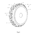
- FIG. 2 shows the hobbing tool 2 from Fig. 1 in a perspective Representation without the workpiece 12. It can be clearly seen how the carrier profile 6 is arranged in a helical line on the lateral surface of the base body 4.
- the carrier profile 6 forms along the base body 4 three courses 11.
- the cutting plates 7, 8, 9 are arranged on the flanks and at the apex of the carrier profile 6.
- the distance of a group of consecutive in the direction of the carrier profile 6 cutting plates 7, 8, 9 increases in one or decreases in the other direction, so that the flanks of the toothing 14 to be produced during a rotation of the Wälzfräswerkmaschines 2 completely by the cutting plates. 7 , 8, 9 are covered.
- the successively increasing or decreasing distance of the cutting plates 7, 8, 9 is in Fig. 1 shown by an example on the support profile 6, to its apex or to its base, extending band.
- FIG. 3 shows a segment of the Wälzfräswerkmaschines 2 in a perspective detail view.
- the cutting plates 7, 8, 9, which are arranged in the top and on the flanks of the carrier profile 6.
- the cutting plates 7, 8, 9 are preceded by chip chambers 5.
- the tapering shape of the cross section of the carrier profile 6 can be clearly seen.
- At 11, three gears formed by the helical course of the carrier profile 6 of the Wälzfrästechnikmaschines 2 can be seen.
- FIG. 4 shows a sectional view of the collar-like carrier profile 6 in the circumferential direction of the base body 4th
- FIG. 5 shows a hobbing tool 2 with a first arrangement inserts 7 in a side view.
- the only difference to the hobbing tool 2 off Fig. 1 is that fewer types of cutting plates are provided.
- FIG. 6 shows a hobbing tool 2 with a second arrangement inserts 8, 9 in a side view.
- the only difference to the hobbing tool 2 off Fig. 1 is that fewer types of cutting plates are provided.
- FIG. 7 shows the hobbing tool 2 from Fig. 1 with a combination of the arrangement of cutting plates 7, 8, 9 made Fig. 5 and Fig. 6 ,
- FIGS. 8 and 9 each show an insert 8, which has a, on the side facing away from the perspective, approximately rectangular, flat base (not shown). In the direction perpendicular to the base surface, a bulge of material forms a total of approximately cuboid base body. On the opposite side of the base surface of the base body of the cutting plate 8 is rounded at two opposite edges. At least one of the edge lying transversely to the rounded edges forms a cutting edge 16.
- a preferably aligned perpendicular to the base bore 18 extends approximately centrally through the body through. Alternatively, the bore 18 may extend at an angle, oblique to the base by the body.
- the cutting plate 8 by means of a screw on the support section 6 of the Wälzfräswerkmaschines 2 (not shown) can be fastened.
- a chip breaker 20 is arranged.
- the chip breaker 20 is inserted as a channel-like depression in the located below the cutting edge 16 side surface of the body and extends at a distance at least in a portion approximately parallel to the cutting edge sixteenth
- FIGS. 10 and 11 show in perspective in each case an insert 7, 8, 9 with a shim 22 and a tuning plate 24th Fig. 10 shows the components in an assembled arrangement, as intended for mounting on a support profile 6 (not shown).
- Fig. 11 shows the arrangement Fig. 10 in an exploded view.
- the shim 22 has an approximately strip-shaped, flat basic shape, wherein a first elongated end of the strip shape tapers into a truncated tip shape.
- the tuning plate 24 has an approximately cuboidal basic shape and has an approximately centrally disposed through hole for attachment to the support section 6 (not shown) by means of a screw 26.
- the Unterlegplatte 22 three through holes are provided, wherein one of the holes for the attachment of the shim 22 to the support section 6 (not shown) is provided by means of a screw 26. In each case via a further bore, the cutting plate 7, 8, 9 and the tuning plate 24 by means of a screw 26 on the support section 6 (not shown) fastened.
- the shim 22 is provided for mounting between the carrier profile 6 (not shown) and the cutting plate 7, 8, 9 with the tuning plate 24. As in Fig. 10 can be seen, are the cutting plate 8, 7, 9 and the tuning plate 24 in the mounted position, each with its base surface on the Unterlegplatte 22.
- the tuning plate 24 is arranged, which rests in the mounted position with a lateral support surface on one side of the cutting plate 7, 8, 9.
- the angular position of the cutting plate 7, 8, 9 with respect to the rotational or longitudinal axis of the base body (not shown) is tunable by the shape of the shim 22 and the shape of the tuning plate 24.
- the angular position of the cutting plate 7, 8, 9 may be specified in particular by a beveled top or bottom of the shim 22 and / or by a tapered bearing surface of the tuning plate 24.
Abstract
Die Erfindung betrifft ein Wälzfräswerkzeug zur Herstellung einer Innenverzahnung an einem Werkstück, wobei eine Mehrzahl von wechselbaren Schneidplatten mit jeweils mindestens einer Schneidkante vorgesehen ist, die Länge der Schneidkanten zumindest einiger Schneidplatten kürzer ist, als die Zahnhöhe der herzustellenden Innenverzahnung, die Schneidplatten an einem kragenartigen Trägerprofil angeordnet sind, wobei das Trägerprofil, mindestens einen Gang bildend, entlang einer Schraubenlinie am Umfang eines Grundkörpers des Wälzfräswerkzeugs verläuft, unterschiedliche Typen von Schneidplatten vorgesehen sind und das Trägerprofil entlang der Schraubenlinie n Abschnitte mit jeweils bezüglich ihrer Winkellage und/oder ihrem radialen Abstand zur Drehachse des Grundkörpers unterschiedlich positionierten Schneidplatten aufweist, so dass sich entlang des Trägerprofils die Form der durch die Schneidplatten der Abschnitte jeweils ausgebildeten Hüllschnitte ändert und wobei mehr Abschnitte vorgesehen sind als Typen von Schneidplatten.The invention relates to a Wälzfräswerkzeug for producing an internal toothing on a workpiece, wherein a plurality of exchangeable cutting plates is provided with at least one cutting edge, the length of the cutting edges of at least some inserts is shorter than the tooth height of the internal teeth to be produced, the inserts on a collar-like carrier profile are arranged, wherein the carrier profile, forming at least one course, along a helical line on the circumference of a base body of Wälzfräswerkzeugs, different types of inserts are provided and the carrier profile along the helix n sections, each with respect to their angular position and / or their radial distance from the axis of rotation the base body has differently positioned cutting plates, so that along the carrier profile, the shape of the formed by the cutting plates of the sections each Hüllschnitte changes and wherein more Sections are provided as types of inserts.
Description
Die Erfindung betrifft ein Wälzfräswerkzeug zur Herstellung einer Innenverzahnung an einem Werkstück.The invention relates to a Wälzfräswerkzeug for producing an internal toothing on a workpiece.
Die Herstellung von Innenverzahnungen in der Weichbearbeitung erfolgt herkömmlich durch Wälzstoßen, Räumen und Formfräsen mit einem oder mehreren parallelen Werkzeugen (Duplex - Triplex Fräser) sowie Innenwälzfräsen (reine Fertigbearbeitung) mit einteiligen Werkzeugen aus einem homogenem Schneidstoff.The production of internal teeth in the soft machining is done conventionally by Wälzstoßen, broaching and form milling with one or more parallel tools (Duplex - Triplex cutter) and internal hobbing (pure finishing) with one-piece tools made of a homogeneous cutting material.
Als Werkzeuge mit Wendeschneidplatten sind bekannt Wälzstoßen mit Stoßrad sowie Formfräser mit Wendeschneidplatten.As tools with indexable inserts are known Wälzstoßen with impeller and form cutter with indexable inserts.
Aus
Aus
Aus
Nachteilig bei den bekannten Wälzfräsern zur Herstellung von Innenverzahnungen ist die eingeschränkte Anpassungsmöglichkeit der Werkzeugschneiden bezüglich unterschiedlicher herzustellender Zahnprofile. Außerdem sind Reparatur und Instandsetzung feststehender Werkzeugschneiden besonders aufwendig und kostenintensiv.A disadvantage of the known hobs for the production of internal gears is the limited possibility of adapting the tool cutting edges with respect to different tooth profiles to be produced. In addition, repair and repair fixed tool cutting are particularly complex and expensive.
Der Erfindung liegt die Aufgabe zugrunde, ein Wälzfräswerkzeug zur Herstellung einer Innenverzahnung bereitzustellen, das einfach und kostengünstig instandgesetzt werden kann. Gleichzeitig soll eine einfache Möglichkeit geschaffen werden, das Wälzfräswerkzeug auf unterschiedliche Flankenformen der herzustellenden Innenverzahnung abzustimmen.The invention has for its object to provide a Wälzfräswerkzeug for producing an internal toothing, which can be easily and inexpensively repaired. At the same time a simple way to create the Wälzfräswerkzeug adapted to different edge shapes of the internal teeth to be produced.
Diese Aufgabe wird durch ein Werkzeug mit den Merkmalen des Anspruchs 1 gelöst.This object is achieved by a tool having the features of claim 1.
Bei dem erfindungsgemäßen Wälzfräswerkzeug zur Herstellung einer Innenverzahnung an einem Werkstück sind eine Mehrzahl von wechselbaren Schneidplatten mit jeweils mindestens einer Schneidkante vorgesehen. Die Länge der Schneidkanten zumindest einiger Schneidplatten ist kürzer, als die Zahnhöhe der herzustellenden Innenverzahnung. Die Schneidplatten sind an einem kragenartigen Trägerprofil angeordnet, wobei das Trägerprofil, mindestens einen Gang bildend, entlang einer Schraubenlinie am Umfang eines Grundkörpers des Wälzfräswerkzeugs verläuft. Es sind unterschiedliche Typen von Schneidplatten vorgesehen und das Trägerprofil weist entlang der Schraubenlinie n Abschnitte mit jeweils bezüglich ihrer Winkellage und/oder ihrem radialen Abstand zur Drehachse oder Längsachse des Grundkörpers unterschiedlich positionierten Schneidplatten auf, so dass sich entlang des Trägerprofils die Form der durch die Schneidplatten der Abschnitte jeweils ausgebildeten Hüllschnitte ändert. Erfindungsgemäß sind mehr Abschnitte vorgesehen als Typen von Schneidplatten. Das Trägerprofil hat insbesondere eine Trapezform. Durch den Einsatz wechselbarer Schneidplatten kann das Schneidprofil des Werkzeugs bei gleichbleibendem Trägerprofil auf unterschiedliche Formen bzw. Typen der herzustellenden Verzahnung angepasst werden. Die auf die herzustellende Verzahnung angepasste Ersatzgeometrie des Werkzeugs kann auf einfache Weise durch die wechselbaren Schneidplatten abgebildet werden.In the hobbing tool according to the invention for producing an internal toothing on a workpiece, a plurality of exchangeable cutting plates are provided, each with at least one cutting edge. The length the cutting edges of at least some inserts is shorter than the tooth height of the internal teeth to be produced. The inserts are arranged on a collar-like carrier profile, the carrier profile, forming at least one passage, runs along a helical line on the circumference of a main body of the hobbing tool. There are different types of inserts provided and the carrier profile along the helix n sections with each with respect to their angular position and / or their radial distance from the axis of rotation or longitudinal axis of the body differently positioned cutting plates, so that along the carrier profile, the shape of the through the cutting plates the sections each changes formed Hüllschnitte. According to the invention, more sections are provided than types of inserts. The carrier profile has in particular a trapezoidal shape. Through the use of exchangeable cutting plates, the cutting profile of the tool can be adapted to different shapes or types of toothing to be produced while the carrier profile remains the same. The replacement geometry of the tool adapted to the toothing to be produced can be imaged in a simple manner by the exchangeable inserts.
Vorzugsweise sind zumindest einige der Schneidplatten Wendeschneidplatten, die jeweils mehr als eine Schneidkante aufweisen. Bei Verschleiß oder Beschädigung einer Schneidkante kann die Schneidplatte vom Trägerprofil gelöst und für den Einsatz mit einer anderen Schneidkante in einer geänderten Stellung wieder montiert werden. Bevorzugt weisen zumindest einige der Schneidplatten jeweils zwei Schneidkanten auf.Preferably, at least some of the inserts are indexable inserts, each having more than one cutting edge. In case of wear or damage of a cutting edge, the cutting plate can be detached from the carrier profile and re-assembled for use with another cutting edge in a changed position. Preferably, at least some of the cutting plates each have two cutting edges.
Der erfindungsgemäße Einsatz von wechselbaren Schneidplatten für das Wälzfräsen einer Innenverzahnung hat den Vorteil, dass dadurch eine höhere Schnittgeschwindigkeit und eine höhere Produktivität erzielt werden kann. Darüber hinaus wird durch die Verwendung wechselbarer Schneidplatten die Möglichkeit geschaffen, die Teilungs- und Profilgenauigkeit der herzustellenden Verzahnung gegenüber Formfäsern mit Schneidplatten zu verbessern. Vorzugsweise weisen zumindest einige der Schneidplatten jeweils ein Substrat bzw. eine Spanleitstufe zur Ableitung von Frässpänen auf.The use according to the invention of interchangeable inserts for hobbing an internal toothing has the advantage that a higher cutting speed and a higher productivity can be achieved thereby. In addition, the possibility of using exchangeable inserts created to improve the pitch and profile accuracy of the toothing to be produced compared to molded fibers with inserts. Preferably, at least some of the cutting plates each have a substrate or a chip breaker for discharging milling chips.
Weiter bevorzugt sind zumindest einige Schneidplatten an dem Trägerprofil in Spannutensteigung angeordnet. Bei dieser Anordnung weisen die Schneidkanten zumindest einiger, entlang der Schraubenlinie des Trägerprofils benachbart liegender, Schneidplatten einen drallförmigen Versatz zu einer Linie auf, die in einem Abstand parallel zur Drehachse oder Längsachse des Werkzeug-Grundkörpers verläuft.More preferably, at least some inserts are arranged on the carrier profile in flute pitch. In this arrangement, the cutting edges of at least some adjacent to the helix of the carrier profile, cutting plates on a spin-shaped offset to a line which extends at a distance parallel to the axis of rotation or longitudinal axis of the tool base body.
Befestigungsmittel sind zur Befestigung der Schneidplatten am Trägerprofil vorgesehen. Vorzugsweise sind die Schneidplatten mittels Schrauben am Trägerprofil befestigbar. Vorzugsweise sind die Schneidplatten jeweils tangential an dem Trägerprofil und in seinem Scheitelbereich befestigt. Des Weiteren können zumindest einige Schneidplatten im Fußbereich, d.h. im unteren Bereich des Trägerprofils befestigt sein.Fasteners are provided for mounting the inserts on the carrier profile. Preferably, the inserts are fastened by means of screws on the carrier profile. Preferably, the cutting plates are each attached tangentially to the carrier profile and in its apex region. Furthermore, at least some cutting plates in the foot area, i. be attached in the lower region of the carrier profile.
Vorzugsweise decken die Schneidkanten der Schneidplatten entlang des Trägerprofils die Eingriffslinie zwischen dem Wälzfräswerkzeug und dem Werkstück ab. Durch diese Anordnung kann jeder Punkt des Flankenprofils der herzustellenden Verzahnung von den Schneidkanten des Werkzeugs erreicht werden.Preferably, the cutting edges of the cutting plates along the support profile cover the line of engagement between the hobbing tool and the workpiece. By this arrangement, each point of the flank profile of the toothing to be produced can be achieved by the cutting edges of the tool.
In einer bevorzugten Ausgestaltung ist die vorgesehene Form einer Zahnlücke der herzustellenden Verzahnung erst durch die Überlagerung der Hüllschnitte aller Abschnitte des Trägerprofils abgebildet.In a preferred embodiment, the intended shape of a tooth gap of the toothing to be produced is shown only by the superimposition of the envelope sections of all sections of the carrier profile.
In einer Ausgestaltung beträgt die Bogenlänge des Trägerprofils mindestens das Einfache, vorzugsweise mindestens das Eineinhalbfache oder mindestens das Zweifache des Umfangs des Grundkörpers.In one embodiment, the arc length of the carrier profile is at least the Simple, preferably at least one-and-a-half times or at least twice the circumference of the basic body.
Vorzugsweise sind an dem Wälzfräswerkzeug Schrupp- und/oder Schlicht-Schneidplatten vorgesehen. Bei einem Werkzeug mit Schrupp- und Schlicht-Schneidplatten kann die Vor- und Fertigbearbeitung durch ein Werkzeug erfolgen. Bei dieser kombinierten Ausführung besteht keine Notwendigkeit, das Werkzeug während der Bearbeitungsschritte auszutauschen oder die Schneidplattentypen des Werkzeugs zu wechseln. Alternativ kann vorgesehen sein, das Werkzeug nur mit Schrupp- oder nur mit Schlicht-Schneidplatten auszustatten. Dies hat den Vorteil einer gezielten, auf das Werkstück abgestimmten Bearbeitung.Preferably, roughing and / or finishing inserts are provided on the hobbing tool. In a tool with roughing and finishing inserts, the pre-machining and finishing can be done by a tool. In this combined embodiment, there is no need to replace the tool during the processing steps or to change the cutting plate types of the tool. Alternatively, it can be provided to equip the tool only with roughing or only with finishing inserts. This has the advantage of a targeted, tailored to the workpiece machining.
In einer bevorzugten Ausgestaltung weist das Wälzfräswerkzeug zehn oder weniger als zehn oder sechs oder weniger als sechs unterschiedliche Typen von Schneidplatten auf. Insbesondere kann vorgesehen sein, dass das Wälzfräswerkzeug fünf oder weniger als fünf oder vier oder weniger als vier unterschiedliche Typen von Schneidplatten aufweist. Die unterschiedlichen Typen von Schneidplatten können sich in der Auswahl des Materials, Substrats, Härtegrad oder anderer Materialeigenschaften unterscheiden. Weiter können sich die Typen durch Ihre Form bzw. Größe unterscheiden. Vorzugsweise sind bei der Kombination von Schrupp- und Schlicht-Schneidplatten zehn oder weniger als zehn oder sechs oder weniger als sechs unterschiedliche Typen von Schneidplatten vorgesehen. Denkbar ist eine Ausgestaltung, bei der die Anzahl der Typen von Schrupp-Schneidplatten um zwei geringer ist, als die Anzahl der Schlicht-Schneidplatten.In a preferred embodiment, the hobbing tool has ten or less than ten or six or less than six different types of inserts. In particular, it may be provided that the hobbing tool has five or less than five or four or less than four different types of inserts. The different types of inserts may differ in the choice of material, substrate, hardness or other material properties. Further, the types may differ by their shape or size. Preferably, the combination of roughing and finishing inserts provides for ten or fewer than ten or six or less than six different types of inserts. A design is conceivable in which the number of types of roughing inserts is smaller by two than the number of size inserts.
In einer Ausgestaltung weist das Wälzfräswerkzeug ausschließlich Schlicht-Schneidplatten auf, wobei fünf oder weniger als fünf unterschiedliche Typen von Schneidplatten vorgesehen sind. Es ist außerdem denkbar, dass das Wälzfräswerkzeug ausschließlich Schrupp-Schneidplatten aufweist.In one embodiment, the hobbing tool exclusively includes sizing inserts, with five or less than five different types of inserts being provided. It is also conceivable that the Wälzfräswerkzeug exclusively has roughing inserts.
Vorzugsweise weisen die Schneidplatten spanbrechende und/oder spanleitende Strukturen auf. Die Strukturen können insbesondere als Spanleitstufe ausgebildet sein. Derartige Strukturen ermöglichen das kontrollierte Brechen bzw. Ableiten von Spänen bei der Bearbeitung des Werkstücks.The inserts preferably have chip-breaking and / or chip-conducting structures. The structures can be designed in particular as a chip breaker. Such structures enable the controlled breaking of chips during machining of the workpiece.
In einer bevorzugten Ausgestaltung sind die Schneidplatten in einem Abstand zur Drehachse oder Längsachse des Grundkörpers angeordnet, wobei sich in Trägerprofilrichtung der jeweilige Abstand für zumindest eine Gruppe aufeinanderfolgender Schneidplatten verringert. Vorzugsweise ist eine Gruppe Schneidplatten an einer ersten Seite des Trägerprofils angeordnet. Insbesondere ist eine Gruppe an einer ersten Seite eines Gangs des Trägerprofils angeordnet.In a preferred embodiment, the cutting plates are arranged at a distance from the axis of rotation or longitudinal axis of the base body, wherein reduced in the carrier profile direction of the respective distance for at least one group of successive inserts. Preferably, a group of cutting plates is arranged on a first side of the carrier profile. In particular, a group is arranged on a first side of a corridor of the carrier profile.
In einer Ausgestaltung sind zumindest einige der Schneidplatten in ihrer Winkellage und/oder in ihrem radialen Abstand zur Drehachse oder Längsachse des Grundkörpers abstimmbar. Vorzugsweise fallen Drehachse und Längsachse des Grundkörpers zusammen. Durch diese Ausgestaltung kann der Steigungswinkel der Schneidplatten bzw. der Schneidkanten entlang des Trägerprofils variiert werden. Der radiale Abstand zur Drehachse bzw. zur Längsachse ist insbesondere der Abstand zwischen der Drehachse bzw. der Längsachse und dem in radialer Richtung gesehene Beginn der Schneidkante einer Schneidplatte. Durch die Abstimmbarkeit der Schneidplatten können z.B. Fertigungs- und/oder Montagetoleranzen ausgeglichen werden.In one embodiment, at least some of the cutting plates are tunable in their angular position and / or in their radial distance from the axis of rotation or longitudinal axis of the main body. Preferably, the axis of rotation and the longitudinal axis of the basic body coincide. By this configuration, the pitch angle of the cutting plates or the cutting edges along the carrier profile can be varied. The radial distance to the axis of rotation or to the longitudinal axis is, in particular, the distance between the axis of rotation or the longitudinal axis and the beginning of the cutting edge of a cutting plate viewed in the radial direction. Due to the tunability of the inserts, e.g. Manufacturing and / or assembly tolerances are compensated.
Die Winkellage und/oder der Abstand der Schneidplatten zur Drehachse oder zur Längsachse des Grundkörpers kann insbesondere durch Unterlegplatten und/oder Abstimmplatten abstimmbar sein. Die Unterlegplatten sind dabei jeweils zur Montage zwischen dem Trägerprofil und den Schneidplatten vorgesehen. Die Abstimmplatten sind jeweils zur Montage radial unterhalb der Schneidplatten vorgesehen. Durch die Ausgestaltung der jeweils an die Schneidplatten grenzenden Auflageflächen der Unterlegplatten bzw. Abstimmplatten können die Schneidplatten in ihrer Lage bezüglich der Dreh- oder Längsachse des Grundkörpers abgestimmt sein. Die Lage der Schneidplatten kann des Weiteren durch die Ausgestaltung der, in der montierten Position an das Trägerprofil angrenzenden Unterseite der Unterlegplatte bestimmt sein. Die Ausgestaltung der Auflageflächen kann z.B. durch das Abtragen von Material bzw. durch die Verwendung von Unterlegplatten bzw. Abstimmplatten mit einem Übermaß vorgegeben sein. Die Bearbeitung der Abstimmplatten und Unterlegplatten kann dabei durch bekannte Arten der Materialbearbeitung wie z.B. gerades oder winkliges Abschleifen oder dergleichen erfolgen.The angular position and / or the distance of the cutting plates to the axis of rotation or to the longitudinal axis of the base body can be tuned in particular by shims and / or tuning plates. The shims are each provided for mounting between the carrier profile and the inserts. The tuning plates are each for mounting radially below the inserts intended. Due to the configuration of each adjacent to the cutting surfaces bearing surfaces of the shims or tuning plates, the inserts can be matched in their position with respect to the rotational or longitudinal axis of the body. The position of the cutting plates can furthermore be determined by the configuration of the underside of the shim bordering the carrier profile in the mounted position. The design of the bearing surfaces can be predetermined for example by the removal of material or by the use of shims or tuning plates with an oversize. The processing of the tuning plates and shims can be done by known types of material processing such as straight or angled grinding or the like.
In einer bevorzugten Ausgestaltung ist das Trägerprofil in Teilstücke unterteilt, wobei die Teilstücke an Bogensegmenten angeordnet sind und wobei die Bogensegmente am Umfang des Grundkörpers befestigbar sind. Dies hat den Vorteil einer einfachen und kostengünstigen Austauschbarkeit verschlissener bzw. beschädigter Teilstücke des Trägerprofils. Vorzugsweise sind die Teilstücke mit den Bogensegmenten mittels Schrauben am Werkzeug-Grundkörper befestigbar. Denkbar ist auch, dass die Bogensegmente mit dem Grundkörper nicht lösbar verbunden sind.In a preferred embodiment, the carrier profile is divided into sections, wherein the sections are arranged on arc segments and wherein the arc segments on the periphery of the body can be fastened. This has the advantage of a simple and cost-exchangeable worn or damaged sections of the carrier profile. Preferably, the sections with the arc segments by means of screws on the tool body can be fastened. It is also conceivable that the arc segments are not detachably connected to the body.
Vorzugsweise weisen die Bogensegmente und/oder der Grundkörper Mittel und/oder Markierungen auf, mit denen zumindest einige Bogensegmente zu einer vorgesehenen Position am Grundkörper zuordenbar sind.Preferably, the arc segments and / or the base body means and / or markings, with which at least some arc segments are assigned to a position provided on the base body.
In einer bevorzugten Ausgestaltung sind zumindest einige der Schneidplatten benachbarter Gänge so versetzt zueinander angeordnet, dass sie durch eine in einer Spankammer eines Gangs des Trägerprofils gebildeten Lücke an dem benachbarten Gang befestigbar sind. Vorzugsweise sind zumindest einige der Schneidplatten im scheitelnahen Bereich des Trägerprofils derart angeordnet, dass sie durch eine Lücke in einer benachbarten Spankammer hindurch an dem Trägerprofil befestigbar sind. Zur Befestigung kann insbesondere ein gerader Schaft eines Schraubendrehers oder dergleichen dienen. Somit sind die jeweiligen Schneidplatten in einfacher Weise unter Zuhilfenahme handelsüblicher bzw. einfach herzustellender Werkzeuge an den Flanken des Trägerprofils befestigbar.In a preferred embodiment, at least some of the cutting plates of adjacent gears are arranged offset from one another in such a way that they can be fastened to the adjacent gear by a gap formed in a chip chamber of a gear of the carrier profile. Preferably, at least some of the inserts are in crest-near region of the carrier profile arranged such that they can be fastened through a gap in an adjacent chip chamber to the carrier profile. For attachment can serve in particular a straight shaft of a screwdriver or the like. Thus, the respective inserts are fastened in a simple manner with the aid of commercially available or easy to produce tools on the flanks of the carrier profile.
Für Schneidplatten, die nicht über Spankammerlücken benachbarter Gänge des Trägerprofils erreichbar sind, kann z.B. der Einsatz eines speziellen Werkzeugs mit einer um 90° abgewinkelten Werkzeugspitze vorgesehen sein. Alternativ oder zusätzlich können Bohrungen in den Gängen des Trägerprofils vorgesehen sein, über die die Schneidplatten benachbarter Gänge erreichbar sind.For inserts which can not be reached via chip gaps of adjacent channels of the carrier profile, e.g. the use of a special tool with a 90 ° angled tool tip be provided. Alternatively or additionally, bores may be provided in the passages of the carrier profile, via which the cutting plates of adjacent passages can be reached.
Für die Befestigung an dem Trägerprofil weisen die Schneidplatten vorzugsweise mindestens eine, insbesondere senkrecht zu ihrer Grundfläche angeordnete Bohrung auf. Abweichend davon kann zumindest bei einigen der Schneidplatten mindestens eine Bohrung in einem Winkel, schräg zur Grundfläche der Schneidplatte vorgesehen sein. Über eine winklige Bohrung kann eine Schneidplatte in einfacher Weise mit einem handelsüblichen Werkzeug mit gerader Werkzeugklinge aus einer schrägen Richtung an dem Trägerprofil befestigt werden.For attachment to the carrier profile, the cutting plates preferably have at least one, in particular arranged perpendicular to its base bore. Deviating from this, at least one bore can be provided at an angle, obliquely to the base surface of the cutting plate, at least in some of the cutting plates. About an angled bore an insert can be easily fixed with a commercial tool with a straight tool blade from an oblique direction to the support section.
In einer weiteren Ausgestaltung sind die Schlicht-Schneidplatten zumindest abschnittsweise in gleicher Winkellage angeordnet. Die Winkellage bezieht sich beispielsweise auf die Drehachse oder die Längsachse des Grundkörpers bzw. eine gedachte Linie, die senkrecht auf der Drehachse oder auf der Längsachse des Grundkörpers steht bzw. auf eine gedachte Linie, die in einem Abstand parallel zur Drehachse oder zur Längsachse des Grundkörpers verläuft. In dieser Ausgestaltung sind die Schlicht-Schneidplatten zumindest abschnittsweise im gleichen Teilungswinkel angeordnet.In a further embodiment, the sizing inserts are at least partially arranged in the same angular position. The angular position relates, for example, to the axis of rotation or the longitudinal axis of the main body or an imaginary line which is perpendicular to the axis of rotation or on the longitudinal axis of the body or to an imaginary line at a distance parallel to the axis of rotation or to the longitudinal axis of the body runs. In this embodiment, the sizing inserts are at least partially arranged at the same pitch angle.
Nachfolgend ist die Erfindung in bevorzugten Ausführungsformen anhand von Zeichnungen näher erläutert. Es zeigen:
- Fig. 1
- ein erfindungsgemäßes Wälzfräswerkzeug in einer schematischen und perspektivischen Darstellung im Eingriff mit einem Werkstück,
- Fig. 2
- das erfindungsgemäße Wälzfräswerkzeug aus
Fig. 1 in einer perspektivischen Gesamtansicht, - Fig. 3
- eine Detailansicht des Wälzfräswerkzeugs aus
Fig. 1 in einer perspektivischen Darstellung, - Fig. 4
- eine Schnittdarstellung im Bereich des Trägerprofils des Wälzfräswerkzeugs aus
Fig. 1 , - Fig. 5
- ein erfindungsgemäßes Wälzfräswerkzeug mit einer ersten Anordnung Schneidplatten in einer Seitenansicht,
- Fig. 6
- ein erfindungsgemäßes Wälzfräswerkzeug mit einer zweiten Anordnung Schneidplatten in einer Seitenansicht,
- Fig. 7
- das Wälzfräswerkzeug aus
Fig. 1 mit einer kombinierten Anordnung Schneidplatten gemäßFig. 5 und Fig. 6 in einer Seitenansicht, - Fig. 8
- eine Schneidplatte in schematisch perspektivischer Darstellung,
- Fig. 9
- eine Schneidplatte aus
Fig. 8 mit zusätzlicher Spanleitstufe in schematisch perspektivischer Darstellung,
- Fig. 10
- eine Schneidplatte aus
Fig. 8 in einer Anordnung mit einer Unterlegplatte und einer Abstimmplatte, - Fig. 11
- eine Explosionsdarstellung der Anordnung aus
Fig. 10 .
- Fig. 1
- an inventive hobbing tool in a schematic and perspective view in engagement with a workpiece,
- Fig. 2
- the Wälzfräswerkzeug invention
Fig. 1 in a perspective overall view, - Fig. 3
- a detailed view of the Wälzfräswerkzeugs
Fig. 1 in a perspective view, - Fig. 4
- a sectional view in the region of the carrier profile of the Wälzfräswerkzeugs
Fig. 1 . - Fig. 5
- an inventive hobbing tool with a first arrangement inserts in a side view,
- Fig. 6
- an inventive hobbing tool with a second arrangement inserts in a side view,
- Fig. 7
- from the hobbing tool
Fig. 1 with a combined arrangement inserts according toFig. 5 and Fig. 6 in a side view, - Fig. 8
- an insert in a schematic perspective view,
- Fig. 9
- an insert
Fig. 8 with additional chip breaker in a schematic perspective view,
- Fig. 10
- an insert
Fig. 8 in an assembly with a shim and a tuning plate, - Fig. 11
- an exploded view of the arrangement
Fig. 10 ,
Claims (17)
Priority Applications (1)
| Application Number | Priority Date | Filing Date | Title |
|---|---|---|---|
| EP13002858.2A EP2810728A1 (en) | 2013-06-03 | 2013-06-03 | Hobbing tool for producing an internal toothing on a workpiece |
Applications Claiming Priority (1)
| Application Number | Priority Date | Filing Date | Title |
|---|---|---|---|
| EP13002858.2A EP2810728A1 (en) | 2013-06-03 | 2013-06-03 | Hobbing tool for producing an internal toothing on a workpiece |
Publications (1)
| Publication Number | Publication Date |
|---|---|
| EP2810728A1 true EP2810728A1 (en) | 2014-12-10 |
Family
ID=48576183
Family Applications (1)
| Application Number | Title | Priority Date | Filing Date |
|---|---|---|---|
| EP13002858.2A Withdrawn EP2810728A1 (en) | 2013-06-03 | 2013-06-03 | Hobbing tool for producing an internal toothing on a workpiece |
Country Status (1)
| Country | Link |
|---|---|
| EP (1) | EP2810728A1 (en) |
Citations (9)
| Publication number | Priority date | Publication date | Assignee | Title |
|---|---|---|---|---|
| DE1083620B (en) | 1959-10-07 | 1960-06-15 | Rohde & Doerrenberg | Hobbing cutter for internal gearing |
| DE1124786B (en) | 1958-12-16 | 1962-03-01 | Fritz Kleinstueck | Double-conical, helical hobbing cutter or grinding body for the production of straight and helical-toothed, involute-shaped internal gear rims |
| DE2827145A1 (en) | 1977-06-22 | 1979-01-04 | Masato Prof Ainoura | BALL-SHAPED HOLLOW MILL FOR THE PRODUCTION OF GEAR WHEELS |
| DE3707664C1 (en) * | 1987-03-10 | 1988-10-13 | Liebherr Verzahntech Gmbh | Machine tool for fine machining the tooth flanks of pre-toothed gears |
| DE202006001112U1 (en) * | 2006-01-25 | 2006-03-23 | Fette Gmbh | hobs |
| CN101066568A (en) | 2007-06-01 | 2007-11-07 | 燕山大学 | Ellipsoidal ring gear hob |
| EP2260964A1 (en) | 2009-06-04 | 2010-12-15 | Vereinigte Pignons Fabriken AG | Method and device for manufacturing an internal gear |
| US20120207553A1 (en) * | 2011-02-11 | 2012-08-16 | Sandvik Intellectual Property Ab | Milling Tool for Gear Milling |
| US20120257935A1 (en) * | 2011-04-08 | 2012-10-11 | Sture Sjoeoe | Milling tool, and milling insert kit |
-
2013
- 2013-06-03 EP EP13002858.2A patent/EP2810728A1/en not_active Withdrawn
Patent Citations (10)
| Publication number | Priority date | Publication date | Assignee | Title |
|---|---|---|---|---|
| DE1124786B (en) | 1958-12-16 | 1962-03-01 | Fritz Kleinstueck | Double-conical, helical hobbing cutter or grinding body for the production of straight and helical-toothed, involute-shaped internal gear rims |
| DE1083620B (en) | 1959-10-07 | 1960-06-15 | Rohde & Doerrenberg | Hobbing cutter for internal gearing |
| DE2827145A1 (en) | 1977-06-22 | 1979-01-04 | Masato Prof Ainoura | BALL-SHAPED HOLLOW MILL FOR THE PRODUCTION OF GEAR WHEELS |
| US4202222A (en) | 1977-06-22 | 1980-05-13 | Masato Ainoura | Method for preparation of spherical hob for generation of gear |
| DE3707664C1 (en) * | 1987-03-10 | 1988-10-13 | Liebherr Verzahntech Gmbh | Machine tool for fine machining the tooth flanks of pre-toothed gears |
| DE202006001112U1 (en) * | 2006-01-25 | 2006-03-23 | Fette Gmbh | hobs |
| CN101066568A (en) | 2007-06-01 | 2007-11-07 | 燕山大学 | Ellipsoidal ring gear hob |
| EP2260964A1 (en) | 2009-06-04 | 2010-12-15 | Vereinigte Pignons Fabriken AG | Method and device for manufacturing an internal gear |
| US20120207553A1 (en) * | 2011-02-11 | 2012-08-16 | Sandvik Intellectual Property Ab | Milling Tool for Gear Milling |
| US20120257935A1 (en) * | 2011-04-08 | 2012-10-11 | Sture Sjoeoe | Milling tool, and milling insert kit |
Similar Documents
| Publication | Publication Date | Title |
|---|---|---|
| DE10330474B4 (en) | Device for producing a gear from a gear blank | |
| EP2243582B1 (en) | Method and device for removing a secondary device on a frontally cogged workpiece wheel | |
| DE102009016257B4 (en) | hobs | |
| EP0085176B1 (en) | Cutter-head for gear-cutting machine | |
| DE202011050054U1 (en) | Skiving tool with knife bars | |
| DE102015106354A1 (en) | Wälzschälverfahren and cutting tool for producing at least partially rounded tooth heads | |
| DE102007015357A1 (en) | Toothing device for fabricating inner or outer toothed gear wheels, where revs of tool spindle matches a multiple of the workpiece spindle | |
| EP2629917A1 (en) | Tooth milling cutter and method for milling the teeth of toothed gear elements | |
| DE102011055210B4 (en) | Threading tool | |
| EP3287221B1 (en) | Method for processing the tooth flanks of plane coupling workpieces in semi-completing single part method | |
| EP2419234B1 (en) | Milling cutter with an internal coolant/lubricant supply | |
| EP3694670B1 (en) | Skiving tool | |
| EP1967307B1 (en) | Method for manufacturing a rotor hub element with grooves | |
| DE20320294U1 (en) | Manufacture of pinion gears used cutting tool that has main milling cutter and a deburring tool | |
| DE3633553A1 (en) | EXTERNAL THREADING TOOL | |
| EP4076808A1 (en) | Tool and method for machining a workpiece | |
| EP2514692A1 (en) | Spoked wheel | |
| EP3512663A1 (en) | Milling tool and production method for a milling tool | |
| EP3141327B1 (en) | Method of dressing a multi-thread grinding worm | |
| EP2537616A1 (en) | Robust method for skiving and corresponding device with skiving tool | |
| EP3477127B1 (en) | Screw for screwing into a hole | |
| WO2015082029A1 (en) | Milling tool and circumferential milling method | |
| DE102010025148A1 (en) | Machining tool i.e. end milling cutter, for machining e.g. rust-free steel, has T-slots arranged between peripheral-sided and front-sided cutting edges, where unequal partition of front-sided cutting edges is provided | |
| EP2810728A1 (en) | Hobbing tool for producing an internal toothing on a workpiece | |
| AT504993A1 (en) | CUTTING PLATE FOR WHEEL SET MACHINING TOOLS |
Legal Events
| Date | Code | Title | Description |
|---|---|---|---|
| PUAI | Public reference made under article 153(3) epc to a published international application that has entered the european phase |
Free format text: ORIGINAL CODE: 0009012 |
|
| 17P | Request for examination filed |
Effective date: 20130603 |
|
| AK | Designated contracting states |
Kind code of ref document: A1 Designated state(s): AL AT BE BG CH CY CZ DE DK EE ES FI FR GB GR HR HU IE IS IT LI LT LU LV MC MK MT NL NO PL PT RO RS SE SI SK SM TR |
|
| AX | Request for extension of the european patent |
Extension state: BA ME |
|
| R17P | Request for examination filed (corrected) |
Effective date: 20150609 |
|
| RBV | Designated contracting states (corrected) |
Designated state(s): AL AT BE BG CH CY CZ DE DK EE ES FI FR GB GR HR HU IE IS IT LI LT LU LV MC MK MT NL NO PL PT RO RS SE SI SK SM TR |
|
| GRAP | Despatch of communication of intention to grant a patent |
Free format text: ORIGINAL CODE: EPIDOSNIGR1 |
|
| INTG | Intention to grant announced |
Effective date: 20180322 |
|
| STAA | Information on the status of an ep patent application or granted ep patent |
Free format text: STATUS: THE APPLICATION IS DEEMED TO BE WITHDRAWN |
|
| 18D | Application deemed to be withdrawn |
Effective date: 20180802 |