EP0453875B1 - Machine for metal cutting - Google Patents
Machine for metal cutting Download PDFInfo
- Publication number
- EP0453875B1 EP0453875B1 EP91105712A EP91105712A EP0453875B1 EP 0453875 B1 EP0453875 B1 EP 0453875B1 EP 91105712 A EP91105712 A EP 91105712A EP 91105712 A EP91105712 A EP 91105712A EP 0453875 B1 EP0453875 B1 EP 0453875B1
- Authority
- EP
- European Patent Office
- Prior art keywords
- tool
- carrier
- axis
- workpiece
- machine according
- Prior art date
- Legal status (The legal status is an assumption and is not a legal conclusion. Google has not performed a legal analysis and makes no representation as to the accuracy of the status listed.)
- Expired - Lifetime
Links
- 238000005520 cutting process Methods 0.000 title claims abstract description 12
- 239000002184 metal Substances 0.000 title description 2
- 238000003801 milling Methods 0.000 claims abstract description 10
- 238000006073 displacement reaction Methods 0.000 claims description 7
- 230000001360 synchronised effect Effects 0.000 claims description 4
- 238000003754 machining Methods 0.000 abstract description 7
- 238000000034 method Methods 0.000 abstract description 3
- 238000013461 design Methods 0.000 description 2
- 238000011161 development Methods 0.000 description 1
- 230000018109 developmental process Effects 0.000 description 1
- 238000005553 drilling Methods 0.000 description 1
- 238000003780 insertion Methods 0.000 description 1
- 230000037431 insertion Effects 0.000 description 1
- 238000009434 installation Methods 0.000 description 1
- 238000003622 knife milling Methods 0.000 description 1
- 238000004519 manufacturing process Methods 0.000 description 1
- 238000012805 post-processing Methods 0.000 description 1
- 238000007781 pre-processing Methods 0.000 description 1
- 238000002360 preparation method Methods 0.000 description 1
- 238000002203 pretreatment Methods 0.000 description 1
- 238000012545 processing Methods 0.000 description 1
- 230000001105 regulatory effect Effects 0.000 description 1
Images


Classifications
-
- B—PERFORMING OPERATIONS; TRANSPORTING
- B23—MACHINE TOOLS; METAL-WORKING NOT OTHERWISE PROVIDED FOR
- B23F—MAKING GEARS OR TOOTHED RACKS
- B23F15/00—Methods or machines for making gear wheels of special kinds not covered by groups B23F7/00 - B23F13/00
-
- B—PERFORMING OPERATIONS; TRANSPORTING
- B23—MACHINE TOOLS; METAL-WORKING NOT OTHERWISE PROVIDED FOR
- B23C—MILLING
- B23C3/00—Milling particular work; Special milling operations; Machines therefor
- B23C3/28—Grooving workpieces
- B23C3/30—Milling straight grooves, e.g. keyways
-
- B—PERFORMING OPERATIONS; TRANSPORTING
- B23—MACHINE TOOLS; METAL-WORKING NOT OTHERWISE PROVIDED FOR
- B23F—MAKING GEARS OR TOOTHED RACKS
- B23F23/00—Accessories or equipment combined with or arranged in, or specially designed to form part of, gear-cutting machines
- B23F23/006—Equipment for synchronising movement of cutting tool and workpiece, the cutting tool and workpiece not being mechanically coupled
-
- Y—GENERAL TAGGING OF NEW TECHNOLOGICAL DEVELOPMENTS; GENERAL TAGGING OF CROSS-SECTIONAL TECHNOLOGIES SPANNING OVER SEVERAL SECTIONS OF THE IPC; TECHNICAL SUBJECTS COVERED BY FORMER USPC CROSS-REFERENCE ART COLLECTIONS [XRACs] AND DIGESTS
- Y10—TECHNICAL SUBJECTS COVERED BY FORMER USPC
- Y10T—TECHNICAL SUBJECTS COVERED BY FORMER US CLASSIFICATION
- Y10T29/00—Metal working
- Y10T29/51—Plural diverse manufacturing apparatus including means for metal shaping or assembling
- Y10T29/5104—Type of machine
- Y10T29/5109—Lathe
-
- Y—GENERAL TAGGING OF NEW TECHNOLOGICAL DEVELOPMENTS; GENERAL TAGGING OF CROSS-SECTIONAL TECHNOLOGIES SPANNING OVER SEVERAL SECTIONS OF THE IPC; TECHNICAL SUBJECTS COVERED BY FORMER USPC CROSS-REFERENCE ART COLLECTIONS [XRACs] AND DIGESTS
- Y10—TECHNICAL SUBJECTS COVERED BY FORMER USPC
- Y10T—TECHNICAL SUBJECTS COVERED BY FORMER US CLASSIFICATION
- Y10T409/00—Gear cutting, milling, or planing
- Y10T409/30—Milling
- Y10T409/304536—Milling including means to infeed work to cutter
- Y10T409/305544—Milling including means to infeed work to cutter with work holder
- Y10T409/305656—Milling including means to infeed work to cutter with work holder including means to support work for rotation during operation
- Y10T409/305712—Milling including means to infeed work to cutter with work holder including means to support work for rotation during operation and including means to infeed cutter toward work axis
-
- Y—GENERAL TAGGING OF NEW TECHNOLOGICAL DEVELOPMENTS; GENERAL TAGGING OF CROSS-SECTIONAL TECHNOLOGIES SPANNING OVER SEVERAL SECTIONS OF THE IPC; TECHNICAL SUBJECTS COVERED BY FORMER USPC CROSS-REFERENCE ART COLLECTIONS [XRACs] AND DIGESTS
- Y10—TECHNICAL SUBJECTS COVERED BY FORMER USPC
- Y10T—TECHNICAL SUBJECTS COVERED BY FORMER US CLASSIFICATION
- Y10T82/00—Turning
- Y10T82/13—Pattern section
Definitions
- the invention relates to a fly cutter milling machine according to the preamble of the main claim.
- Such a machine is known from DE-OS 26 50 955, the tool carrier carrying an impact knife for simultaneous milling of several grooves in a rotating workpiece.
- Machines for the production of gearwheels, in which the tool is designed as a hobbing head, are also known.
- To design the positive-running device between the tool spindle and workpiece spindle as an "electronic gear” is known, for. B. from wt Maschinenstattechnik 79/1989, page 677.
- high-precision synchronous operation between a leading axis and several following axes is ensured by electronic regulating and control units.
- a disadvantage of known machines is their limited usability. These machines are only suitable for gearing the workpieces or only for turning. It is therefore not possible, for example, to carry out turning work on the rotating workpiece on a generic machine, since the workpiece speed cannot be adjusted to the height required for the necessary cutting speed. Due to the forced movement between the tool holder and the workpiece holder, the latter always runs slower than the tool holder by the number of teeth on the workpiece. A pre-treatment and post-treatment of the workpieces by turning or the like requires another processing machine.
- the invention is therefore based on the object of specifying a generic machine in which, in addition to milling, the workpiece can also be machined by other machining methods.
- a generic machine for machining metal which is particularly suitable for pre- or post-processing of gears by means of turning, drilling or finger milling.
- the supplementary tool in order to first preform a blank to be toothed, it can be machined with the supplementary tool sitting on the tool slide and carried by a carrier.
- the supplementary tool can be brought into the working position by a relative movement of the supplementary tool carrier and can be delivered to the workpiece in the directions of displacement of the tool carrier.
- the relative movement can take place, for example, by shifting an adjustment slide of the supplementary tool carrier, the supplementary tool being fastened on the adjustment slide.
- the tool carrier moves into a rear-shifted position and can be decoupled from the electronic forced-running device and, for example, stand still.
- the supplementary tool is preferably carried by the housing of the tool holder chuck, so that it can be moved on the tool carriage while sitting on it.
- the supplementary tool is designed as a turning tool.
- the speed of the workpiece carrier can be varied within a wide range when machining with the supplementary tool, with the tool carrier stationary, so that the high cutting speeds required for turning on the workpiece that is clamped in the tool carrier are achieved can be.
- the workpiece carrier speed can be set, for example, in a range from 0 to about 3000 rpm.
- the additional axial displaceability of the tool carrier (in the direction of its extension axis) ensures optimal infeed, for example of a turning tool. All axial displacements (linear displacements) of the machine can preferably be controlled electronically and synchronized with the workpiece rotation. This also enables non-circular profiles to be turned.
- the usability of the machine is further increased by the fact that several turning tools are provided and the supplementary tool carrier is designed as a tool changing device.
- the latter is preferably designed as a revolver.
- the design of the workpiece carrier drive as decouplable from the electronic positive-running device further enables the step-by-step control of the workpiece spindle.
- the supplementary tool is preferably designed as a milling cutter or drill.
- the supplementary tool can be moved in the three spatial directions by displacing the tool carrier.
- the rotating tool is designed as a hobbing cutter or fly knife
- This allows Narrow gear wheels can also be produced using hobbing or, in the case of fly cutter milling, a helical profile.
- the axial displaceability of the tool slide proves to be particularly advantageous since several tools, which may also be different, can thereby be arranged axially offset from one another.
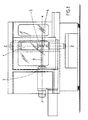
- the machine shown in FIGS. 1-4 has a rotating, stationary workpiece carrier 2, which is driven by an electric individual drive 7.
- the workpiece 3 is clamped at one end in the chuck of the workpiece carrier 2. At its other end, the workpiece 3 is held by a bearing block 8.
- the axis of rotation of workpiece carrier 2 and workpiece 3 forms the x-axis.
- the striking knives 4 are arranged on a tool carrier 5 rotating about the z-axis.
- the tool carrier 5 is clamped in a tool carrier chuck 25 at one end. With its other end, the tool carrier 5 is clamped in a bearing block 9.
- the tool holder chuck 25 is mounted in a housing 1.
- Housing 1 tool holder 5 and bearing block 9 are assigned to a tool slide 16 which can be displaced in the z direction 11.
- the tool carrier 5 is driven by an electric individual drive 6.
- the individual electric drives 6, 7 for the tool holder 5 and for the workpiece holder 2 are positively controlled by an electronic synchronizing device 13.
- the tool can be advanced in the y-direction 10 to advance the tool 4 during gear cutting work on the workpiece.
- a feed carriage 15 is provided, which can be moved by an electric drive.
- the feed carriage 15 is mounted on a drive-in carriage 14 which can also be displaced in the x direction by an electric drive 24.
- a swivel support 17 is arranged on the feed carriage 15 and can be swiveled about the y-axis running perpendicular to the x and z axes.
- the tool slide 16, which is the carrier of the tool carrier chuck 25 and the bearing block 9, is arranged in a rotationally fixed manner with the pivot carrier 17, but can also be displaced thereon in the z direction 11 by an electric drive.
- the x-axis and y-axis are skewed to one another, the z-axis being pivotable about an axis y which perpendicularly intersects both the x and z axes.
- the tool carrier 5 has several impact knives 4 which are axially separated from one another in the z direction. This makes it easy to change the flyknives used.
- the tool carriage 16 only needs to be displaced in the z direction in such a way that another fly knife 4 is brought into the use position. The position of the axes x, y, relative to one another does not change at all with this shift. Only the tool is changed.
- the tool carriage 16 can be displaced independently in the z and y directions, a supplementary tool 21 seated thereon can be advanced in the plane spanned by the y and z axes.
- the supplementary tool 21 is designed as a lathe chisel which is clamped in a clamping device 20 which is fixedly mounted on an adjusting slide 19.
- the adjustment slide 19 can be displaced longitudinally displaceably on a support block.
- the supplementary tool carrier 18, which consists of the support frame, adjusting slide 19 and tool clamping device 20, is fastened with its support frame to the housing 1 of the tool holder chuck 25 (see FIGS. 1-4) by displacing the longitudinally displaceable adjusting slide 19 in the z direction the turning tool 21 can be brought into its working position, in which it cuts the rotating workpiece 3.
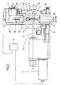
- Figures 5 and 6 show a further embodiment of the supplementary tool holder 18, which is mounted on the housing 1 of the tool holder chuck 25, as a tool changer 22, which is designed as a turret and each has four tool positions offset by 90 °, three of which have turning tools 21 are equipped.
- a tool changer 22 which is designed as a turret and each has four tool positions offset by 90 °, three of which have turning tools 21 are equipped.
- the rotation of the tool carrier 5 is stopped, the electrical drive 6 of the tool and the electrical drive 7 of the workpiece being decoupled from the synchronizing device 13.
- the electric drive 7 of the workpiece carrier 2 now runs so that the high cutting speeds required for turning can be achieved.
- the turning tool 21 is fed to the workpiece 3.
- the turning of the turning tool in the x direction takes place by moving the entry slide 14.
- a workpiece 3 toothed by means of a knife 4 can thus be deburred in a simple manner on the end faces of the toothing.
- the workpiece carrier 2, which rotates slower than the tool carrier 5 in the toothing by the number of teeth of the workpiece, is uncoupled from the positive running device 13 after the toothing, so that it can be controlled directly via the individual drive 7.
- the speed of the workpiece 3 no longer depends on the maximum speed of the tool carrier 5 and can therefore be increased in such a way that the high cutting speeds necessary for turning are achieved.
- the electric drives of feed carriage 15, entry carriage 14 and tool carriage 16 can be synchronized with the individual drive 7. Such a configuration makes it possible to rotate non-round profiles.
- the tool drive 6 is also uncoupled from the positive-running device and stands still.
- the supplementary tool will be a drill or a end mill.
- the supplementary tool can be assigned to a tool changer.
Landscapes
- Engineering & Computer Science (AREA)
- Mechanical Engineering (AREA)
- Turning (AREA)
- Machine Tool Units (AREA)
- Automatic Tool Replacement In Machine Tools (AREA)
- Electrical Discharge Machining, Electrochemical Machining, And Combined Machining (AREA)
Abstract
Description
Die Erfindung betrifft eine Schlagmesser-Fräsmaschine gemäß Oberbegriff des Hauptanspruchs.The invention relates to a fly cutter milling machine according to the preamble of the main claim.
Eine derartige Maschine ist aus der DE-OS 26 50 955 bekannt, wobei der Werkzeugträger ein Schlagmesser trägt, zum gleichzeitigen Einfräsen mehrerer Nuten in ein umlaufendes Werkstück. Weiterhin bekannt sind Maschinen zur Herstellung von Zahnrädern, bei denen das Werkzeug als Wälzfräskopf ausgebildet ist. Die Zwanglaufeinrichtung zwischen Werkzeugspindel und Werkstückspindel als "elektronisches Getriebe" auszugestalten, ist bekannt z. B. aus wt Werkstattechnik 79 /1989, Seite 677. Hierbei wird ein hochgenauer Synchronlauf zwischen einer Leitachse und mehreren Folgenachsen durch elektronische Regel- und Steuereinheiten gewährleistet.Such a machine is known from DE-OS 26 50 955, the tool carrier carrying an impact knife for simultaneous milling of several grooves in a rotating workpiece. Machines for the production of gearwheels, in which the tool is designed as a hobbing head, are also known. To design the positive-running device between the tool spindle and workpiece spindle as an "electronic gear" is known, for. B. from wt Werkstattechnik 79/1989, page 677. Here, high-precision synchronous operation between a leading axis and several following axes is ensured by electronic regulating and control units.
Nachteilhaft an bekannten Maschinen ist jedoch ihre beschränkte Einsatzfähigkeit. Diese Maschinen sind nur zur Verzahnung der Werkstücke geeignet oder nur zur Drehbearbeitung. Es ist daher zum Beispiel nicht möglich, an einer gattungsgemäßen Maschine Dreharbeiten am rotierenden Werkstück durchzuführen, da die Werkstückdrehzahl nicht auf die für die nötige Schnittgeschwindigkeit benötigte Höhe einstellbar ist. Durch den Zwanglauf zwischen Werkzeugträger und Werkstückträger läuft letzterer immer um die Anzahl der Zähne des Werkstückes langsamer als der Werkzeugträger. Eine Vor- und Nachbehandlung der Werkstücke durch Drehen oder ähnliches erfordert eine weitere Bearbeitungsmaschine.A disadvantage of known machines, however, is their limited usability. These machines are only suitable for gearing the workpieces or only for turning. It is therefore not possible, for example, to carry out turning work on the rotating workpiece on a generic machine, since the workpiece speed cannot be adjusted to the height required for the necessary cutting speed. Due to the forced movement between the tool holder and the workpiece holder, the latter always runs slower than the tool holder by the number of teeth on the workpiece. A pre-treatment and post-treatment of the workpieces by turning or the like requires another processing machine.
Der Erfindung liegt daher die Aufgabe zugrunde, eine gattungsgemäße Maschine anzugeben, bei der neben Fräsbearbeiten das Werkstück auch durch andere spanabhebende Bearbeitungsweisen bearbeitet werden kann.The invention is therefore based on the object of specifying a generic machine in which, in addition to milling, the workpiece can also be machined by other machining methods.
Gelöst wird diese Aufgabe durch die kennzeichnenden Merkmale des Hauptanspruchs. Die Unteransprüche stellen vorteilhafte Weiterbildungen dar.This task is solved by the characteristic features of the main claim. The subclaims represent advantageous developments.
Zufolge der erfindungsgemäßen Ausgestaltung ist eine gattungsgemäße Maschine zur spanenden Metallbearbeitung gegeben, die sich insbesondere zur Vor- oder Nachbearbeitung von Zahnrädern mittels Drehen, Bohren oder Fingerfräsen eignet. Um z.B. einen zu verzahnenden Rohling zunächst vorzuformen, kann dieser mit dem auf dem Werkzeugschlitten sitzenden, von einem Träger getragenen Ergänzungswerkzeug bearbeitet werden. Es ist aber auch möglich, ein bereits verzahntes Werkstück nachträglich durch Drehen oder Fräsen, ohne erneutes Ein- und Ausspannen von Werkzeugen weiterzubearbeiten. Hierzu ist das Ergänzungswerkzeug durch eine Relativbewegung des Ergänzungswerkzeug-Trägers in Arbeitsstellung bringbar und in den Verlagerungsrichtungen des Werkzeugträgers dem Werkstück zustellbar. Die Relativbewegung kann z.B. durch eine Verschiebung eines Einstellschlittens des Ergänzungswerkzeug-Trägers erfolgen, wobei das Ergänzungswerkzeug auf dem Einstellschlitten befestigt ist. Hierzu tritt der Werkzeugträger in eine rückverlagerte Stellung und kann von der elektronischen Zwanglaufeinrichtung abgekoppelt sein und beispielsweise stillstehen. Bevorzugt wird das Ergänzungswerkzeug vom Gehäuse des Werkzeugträgerspannfutters getragen, daß auf dem Werkzeugschlitten sitzend mit diesem zusammen verlagerbar ist. Gemäß einer weiteren bevorzugten Ausgestaltung der Erfindung ist das Ergänzungswerkzeug als Drehmeißel ausgestaltet. Durch die Abkoppelbarkeit der elektronischen Einzelantriebe von Werkzeugträger und Werkstückträger kann bei der Bearbeitung mit dem Ergänzungswerkzeug, bei stillstehendem Werkzeugträger die Drehzahl des Werkstückträgers in einem großen Bereich variiert werden, so daß die zur Drehbearbeitung notwendigen hohen Schnittgeschwindigkeiten am Werkstück, das im Werkzeugträger eingespannt ist,erreicht werden können. Die Werkstückträgerdrehzahl kann dabei beispielsweise in einem Bereich von 0 bis etwa 3000 U/min eingestellt werden. Durch die zusätzliche axiale Verlagerbarkeit des Werkzeugträgers (in Richtung seiner Erstreckungsachse) ist ein optimales Zustellen z.B. eines Drehmeißels gewährleistet. Vorzugsweise sind sämtliche axialen Verlagerungen (lineare Verschiebungen) der Maschine elektronisch ansteuerbar und mit der Werkstückdrehung synchronisierbar. Hierdurch ist auch das Drehen von unrunden Profilen ermöglicht. Die Einsatzfähigkeit der Maschine wird weiterhin dadurch erhöht, daß mehrere Drehmeißel vorgesehen sind und der Ergänzungswerkzeug-Träger als Werkzeugwechselvorrichtung gestaltet ist. Vorzugsweise ist letzterer als Revolver ausgestaltet. Die Verlagerbarkeit des Werkzeugträgers - im Wege der Werkzeugschlittenverschiebung - in Richtung seiner schwenkbaren Erstreckungsachse zusätzlich zur Verlagerbarkeit des Einfahrschlittens des Werkzeugträgers senkrecht zur Werkstückachse gewährleistet, daß der Drehmeißel immer im vorgeschriebenen Anstellwinkel zustellbar ist. Die Ausgestaltung des Werkstückträger-Antriebs als von der elektronischen Zwanglaufeinrichtung abkoppelbar ermöglicht weiterhin die schrittweise Steuerung der Werkstückspindel. Vorzugsweise ist bei diesem Betrieb das Ergänzungswerkzeug als Fingerfräser oder Bohrer ausgebildet. Bei diesem Betrieb mit stillstehendem Werkstück ist zur Bearbeitung das Ergänzungswerkzeug über Verlagerungen des Werkzeugträgers in den drei Raumrichtungen bewegbar. Gemäß einer weiteren vorteilhaften Ausgestaltung, bei der das umlaufende Werkzeug als Wälzfräskopf oder Schlagmesser ausgebildet ist, stehen nicht nur die beiden Einzelantriebe von Werkzeugträger und Werkstückträger in Zwanglauf zueinander, sondern auch mit dem Verlagerungsantrieb des Werkzeugträgers in der Werkstückdrehachse. Hierdurch können mittels Wälzfräsen auch breite Zahnräder hergestellt werden oder im Falle des Schlagmesserfräsens eine schraubenförmige Profilierung. Beim Wälz- oder Schlagmesserfräsen erweist sich insbesondere die axiale Verschiebbarkeit des Werkzeugschlittens von Vorteil, da hierdurch mehrere unter Umständen auch verschiedene Werkzeuge axial versetzt voneinander angeordnet sein können. Es ist somit möglich, bei automatischer Werkstückzu- und Abführung, die Intervalle zwischen dem Ein- und Ausbau der Werkzeuge zu erhöhen, da in einfacher Weise durch axiale Verlagerung des Werkzeugschlittens ein Werkzeugwechsel erzielt werden kann. Der axiale Werkzeugwechsel erweist sich auch dann von Vorteil, wenn verschiedenartige Verzahnungen an einem Werkstück vorgenommen werden sollen. Es können dann verschiedenartige Werkzeuge in axialem Abstand am Werkzeugträger angeordnet sein.As a result of the configuration according to the invention, there is a generic machine for machining metal, which is particularly suitable for pre- or post-processing of gears by means of turning, drilling or finger milling. For example, in order to first preform a blank to be toothed, it can be machined with the supplementary tool sitting on the tool slide and carried by a carrier. However, it is also possible to further process an already toothed workpiece by turning or milling, without having to re-clamp and re-clamp tools. For this purpose, the supplementary tool can be brought into the working position by a relative movement of the supplementary tool carrier and can be delivered to the workpiece in the directions of displacement of the tool carrier. The relative movement can take place, for example, by shifting an adjustment slide of the supplementary tool carrier, the supplementary tool being fastened on the adjustment slide. For this purpose, the tool carrier moves into a rear-shifted position and can be decoupled from the electronic forced-running device and, for example, stand still. The supplementary tool is preferably carried by the housing of the tool holder chuck, so that it can be moved on the tool carriage while sitting on it. According to a further preferred embodiment of the invention, the supplementary tool is designed as a turning tool. Due to the fact that the electronic individual drives of the tool carrier and workpiece carrier can be disconnected, the speed of the workpiece carrier can be varied within a wide range when machining with the supplementary tool, with the tool carrier stationary, so that the high cutting speeds required for turning on the workpiece that is clamped in the tool carrier are achieved can be. The workpiece carrier speed can be set, for example, in a range from 0 to about 3000 rpm. The additional axial displaceability of the tool carrier (in the direction of its extension axis) ensures optimal infeed, for example of a turning tool. All axial displacements (linear displacements) of the machine can preferably be controlled electronically and synchronized with the workpiece rotation. This also enables non-circular profiles to be turned. The usability of the machine is further increased by the fact that several turning tools are provided and the supplementary tool carrier is designed as a tool changing device. The latter is preferably designed as a revolver. The displaceability of the tool carrier - by way of the tool slide displacement - in the direction of its pivotable extension axis, in addition to the displaceability of the insertion slide of the tool carrier perpendicular to the workpiece axis, ensures that the turning tool can always be set at the prescribed angle of attack. The design of the workpiece carrier drive as decouplable from the electronic positive-running device further enables the step-by-step control of the workpiece spindle. In this operation, the supplementary tool is preferably designed as a milling cutter or drill. In this operation with the workpiece stationary, the supplementary tool can be moved in the three spatial directions by displacing the tool carrier. According to a further advantageous embodiment, in which the rotating tool is designed as a hobbing cutter or fly knife, not only are the two individual drives of the tool carrier and workpiece carrier in positive rotation with one another, but also with the displacement drive of the tool carrier in the workpiece axis of rotation. This allows Narrow gear wheels can also be produced using hobbing or, in the case of fly cutter milling, a helical profile. In the case of hobbing or chopping knife milling, the axial displaceability of the tool slide proves to be particularly advantageous since several tools, which may also be different, can thereby be arranged axially offset from one another. It is thus possible to increase the intervals between the installation and removal of the tools in the case of automatic workpiece supply and removal, since a tool change can be achieved in a simple manner by axially displacing the tool slide. The axial tool change also proves to be advantageous when different types of toothing are to be carried out on a workpiece. Different types of tools can then be arranged at an axial distance on the tool carrier.
In den nachstehenden Zeichnungen wird die Erfindung anhand von Ausführungsbeispielen erläutert. Es zeigt:
- Fig. 1 eine Gesamtansicht einer gattungsgemäßen Maschine,
- Fig. 2 eine schematische Darstellung der Antriebe einer erfindungsgemäßen Maschine in Ansicht,
- Fig. 3 eine Darstellung gemäß Fig. 2 in Seitenansicht,
- Fig. 4 eine Darstellung gemäß Fig. 2 in Draufsicht,
- Fig. 5 die Detailansicht eines Werkzeugträgers einer weiteren Ausführungsform und
- Fig. 6 eine Seitenansicht gemäß Fig. 5.
- 1 is an overall view of a generic machine,
- 2 shows a schematic representation of the drives of a machine according to the invention,
- 3 is an illustration according to FIG. 2 in side view,
- 4 is a view according to FIG. 2 in plan view,
- 5 shows the detailed view of a tool carrier of a further embodiment and
- 6 is a side view of FIG .. 5
Die in Figur 1-4 dargestellte Maschine weist einen rotierenden, ortsfesten Werkstückträger 2 auf, der von einem elektrischen Einzelantrieb 7 angetrieben wird. In dem Spannfutter des Werkstückträgers 2 ist das Werkstück 3 an seinem einen Ende eingespannt. An seinem anderen Ende ist das Werkstück 3 durch einen Lagerbock 8 gehaltert. Die Rotationsachse von Werkstückträger 2 und Werkstück 3 bildet die x-Achse. Von der x-Achse beabstandet befinden sich Schlagmesser 4. Die Schlagmesser 4 sind an einem um die z-Achse rotierenden Werkzeugträger 5 angeordnet.Der Werkzeugträger 5 ist in einem Werkzeugträgerspannfutter 25 mit seinem einen Ende eingespannt. Mit seinem anderen Ende ist der Werkzeugträger 5 in einem Lagerbock 9 eingespannt. Das Werkzeugträgerspannfutter 25 lagert in einem Gehäuse 1. Gehäuse 1, Werkzeugträger 5 und Lagerbock 9 sind einem in z-Richtung 11 verlagerbaren Werkzeugschlitten 16 zugeordnet. Der Werkzeugträger 5 wird von einem elektrischen Einzelantrieb 6 angetrieben. Die elektrischen Einzelantriebe 6, 7 für den Werkzeugträger 5 und für den Werkstückträger 2 werden von einer elektronischen Synchronisiereinrichtung 13 zwangsgesteuert.The machine shown in FIGS. 1-4 has a rotating,
Zur Zustellung des Werkzeuges 4 bei Verzahnarbeiten am Werkstück kann das Werkzeug in der y-Richtung 10 zugestellt werden. Hierzu ist ein Vorschubschlitten 15 vorgesehen, der von einem elektrischen Antrieb bewegt werden kann. Der Vorschubschlitten 15 lagert auf einem Einfahrschlitten 14, der in x-Richtung ebenfalls durch einen elektrischen Antrieb 24 verlagerbar ist. Auf dem Vorschubschlitten 15 ist ein Schwenkträger 17 angeordnet, der um die senkrecht zur x- und zur z-Achse verlaufenden y-Achse schwenkbar ist. Drehfest mit dem Schwenkträger 17 verbunden, auf diesem jedoch in z-Richtung 11 ebenfalls durch einem elektrischen Antrieb verlagerbar, ist der Werkzeug-Schlitten 16 angeordnet, der Trägervon Werkzeugträgerspannfutter 25 und Lagerbock 9 ist. X-Achse und y-Achse stehen windschief zueinander, wobei die z-Achse um eine Achse y schwenkbar ist, die senkrecht sowohl x- als auch z-Achse schneidet.The tool can be advanced in the y-
Soweit beschrieben, lassen sich mit dieser Maschine Verzahnungen in bekannter Weise durchführen. Der Werkzeugträger 5 weist mehrere in z-Richtung axial voneinander getrennte Schlagmesser 4 auf. Dieses ermöglicht ein einfaches Wechseln der verwendeten Schlagmesser. DerWerkzeug-Schlitten 16 braucht lediglich in der z-Richtung derart verlagert werden, daß ein anderes Schlagmesser 4 in die Einsatzposition gebracht wird. An der Stellung der Achsen x, y , relativ zueinander ändert sich bei dieserverlagerung überhaupt nichts. Es wird lediglich das Werkzeug gewechselt.As far as described, gearing can be carried out in a known manner with this machine. The
Durch die unabhängige Verlagerbarkeit in z- und y-Richtung des Werkzeugschlittens 16 ist eine Zustellung eines darauf sitzenden Ergänzungswerkzeuges 21 in der von der y- und z-Achse aufgespannten Ebene möglich. Das Ergänzungswerkzeug 21 ist in diesem Ausführungsbeispiel als Drehmeißel ausgestaltet, das in einer Einspannvorrichtung 20 eingespannt ist, die fest auf einem Einstellschlitten 19 montiert ist. Der Einstellschlitten 19 ist auf einem Trägerbock längsverschieblich verlagerbar. Der Ergänzungswerkzeug-Träger 18, der aus Trägerbock, Einstellschlitten 19 und Werkzeugeinspannvorrichtung 20 besteht, ist mit seinem Trägerbock auf dem Gehäuse 1 des Werkzeugträgerspannfutter 25 befestigt (vgl. Fig. 1-4) Durch Verlagern des längsverschieblich montierten Einstellschlitten 19 in z-Richtung ist der Drehmeißel 21 in seine Arbeitsstellung bringbar, in welcher er spanabhebend am rotierenden Werkstück 3 angreift.Because the
Die Figuren 5 und 6 zeigen eine weitere Ausgestaltung des Ergänzungswerkzeugträgers 18, der auf dem Gehäuse 1 des Werkzeugträgerspannfutters 25 montiert ist, als einen Werkzeugwechsler 22, der als Revolver ausgestaltet ist und jeweils um 90° versetzt vier Werkzeug positionen aufweist, von denen drei mit Drehmeißeln 21 bestückt sind. Durch Drehung des Werkzeugwechslers um seine Drehachse um jeweils 90° kann einer der drei Drehmeißel 21 in die Arbeitsstellung gebracht werden, die während des Verzahnens von der freien Werkzeugposition 23 eingenommen wird. Die freie Werkzeugposition 23 ist während des Verzahnens in Richtung des Werkzeugträgers 5 so ausgerichtet, daß bei den Verzahnarbeiten kein störender Drehmeißel in den Bearbeitungsraum einragt. Durch Rotation des Werkzeugwechsters (Revolvers) 22 können die Drehmeißel in Position 23 gebracht werden, wobei dann der Drehmeißel dem Werkstück 3 zustellbar ist durch Verlagerung des Vorschubschlittens 15 in y-Richtung und Werkzeugschlitten in z-Richtung.Figures 5 and 6 show a further embodiment of the
Zum Vor- bzw. Nacharbeiten von Zahnrädern mittels Drehen wird die Rotation des Werkzeugträgers 5 stillgelegt, wobei der elektrische Antrieb 6 des Werkzeugs und der elektrische Antrieb 7 des Werkstücks von der Synchronisiereinrichtung 13 abgekoppelt werden. Der elektrische Antrieb 7 des Werkstückträgers 2 läuft nunmehr so, daß die zum Drehen benötigten hohen Schnittgeschwindigkeiten erreicht werden können. Durch Verlagerung von Vorschubschlitten 15 und Werkzeugschlitten 16 in y- bzw. z-Richtung wird der Drehmeißel 21 dem Werkstück 3 zugestellt. Die Verlagerung des Drehmeißels in x-Richtung erfolgt durch die Verlagerung des Einfahrtschlitten 14.For the preparation or reworking of gears by turning, the rotation of the
Ein mittels Schlagmesser 4 verzahntes Werkstück 3 kann somit in einfacher Weise an den Stirnflächen der Verzahnung entgratet werden. Der bei der Verzahnung um die Anzahl der Zähne des Werkstückes langsamer als der Werkzeugträger 5 drehende Werkstückträger 2 wird nach dem Verzahnen von der Zwanglaufeinrichtung 13 abgekuppelt, so daß sie über den Einzelantrieb 7 direkt angesteuert werden kann. Die Drehzahl des Werkstücks 3 hängt nun nicht mehr von der maximalen Drehzahl des Werkzeugträgers 5 ab und kann deshalb derart erhöht werden , daß die zum Abdrehen notwendigen hohen Schnittgeschwindigkeiten erreicht werden. Es ist vorgesehen, daß die elektrischen Antriebe von Vorschubschlitten 15, Einfahrschlitten 14 und Werkzeugschlitten 16 mit dem Einzelantrieb 7 synchronisierbar sind. Eine solche Ausgestaltung ermöglicht es, unrunde Profile zu drehen. Während der Dreharbeiten ist auch der Werkzeugantrieb 6 von der Zwanglaufeinrichtung abgekoppelt und steht still.A
Es ist ebenfalls vorgesehen, daß das Ergänzungswerkzeug ein Bohrer oder ein Fingerfräser ist. Auch hierbei kann das Ergänzungswerkzeug einem Werkzeugwechsler zugeordnet sein. Bei der Bearbeitung eines Werkstückes 3 mit letztgenannten Werkzeugen ist vorgesehen, daß der Werkstückträger 2 sich nicht kontinuierlich dreht, sondern schritttweise weitergedreht wird. Die Bearbeitung des Werkstückes erfolgt dann bei stillstehendem Werkstück.It is also contemplated that the supplementary tool will be a drill or a end mill. Here too, the supplementary tool can be assigned to a tool changer. When machining a
Claims (15)
Priority Applications (1)
| Application Number | Priority Date | Filing Date | Title |
|---|---|---|---|
| AT91105712T ATE91934T1 (en) | 1990-04-26 | 1991-04-11 | METAL CUTTING MACHINE. |
Applications Claiming Priority (2)
| Application Number | Priority Date | Filing Date | Title |
|---|---|---|---|
| DE4013327 | 1990-04-26 | ||
| DE4013327A DE4013327C2 (en) | 1990-04-26 | 1990-04-26 | Metal cutting machine |
Publications (3)
| Publication Number | Publication Date |
|---|---|
| EP0453875A1 EP0453875A1 (en) | 1991-10-30 |
| EP0453875B1 true EP0453875B1 (en) | 1993-07-28 |
| EP0453875B2 EP0453875B2 (en) | 2002-05-15 |
Family
ID=6405149
Family Applications (1)
| Application Number | Title | Priority Date | Filing Date |
|---|---|---|---|
| EP91105712A Expired - Lifetime EP0453875B2 (en) | 1990-04-26 | 1991-04-11 | Machine for metal cutting |
Country Status (4)
| Country | Link |
|---|---|
| US (1) | US5159741A (en) |
| EP (1) | EP0453875B2 (en) |
| AT (1) | ATE91934T1 (en) |
| DE (2) | DE4013327C2 (en) |
Families Citing this family (8)
| Publication number | Priority date | Publication date | Assignee | Title |
|---|---|---|---|---|
| DE9110812U1 (en) * | 1991-05-02 | 1992-08-27 | Wera-Werk Hermann Werner Gmbh & Co, 5600 Wuppertal | Machine for machining rotating workpieces |
| DE4225509A1 (en) * | 1992-08-01 | 1994-02-03 | Werner Hermann Wera Werke | Machine tool |
| TW301619B (en) * | 1994-10-07 | 1997-04-01 | Toshiba Machine Co Ltd | |
| DE4446475C2 (en) * | 1994-12-23 | 2000-06-21 | Boehringer Werkzeugmaschinen | Method and machine for machining workpieces |
| JP3950476B2 (en) * | 1995-06-06 | 2007-08-01 | ヴィディア ゲゼルシャフト ミット ベシュレンクテル ハフツング | Milling cutting method for cutting cylindrical contour body and cutting apparatus for performing the milling method |
| WO2003084702A1 (en) * | 2002-04-05 | 2003-10-16 | Beier Entgrattechnik Spezial - Entgrat Werkzeuge | Deburring tool for deburring on the interior and/or exterior |
| CN105817683B (en) * | 2016-03-30 | 2018-06-22 | 上海运良转向节有限公司 | Circular groove milling cutter device |
| DE102017115089B4 (en) * | 2017-07-06 | 2019-04-25 | Klaus Union Gmbh & Co. Kg | Method of manufacturing a rotor for a screw pump |
Family Cites Families (10)
| Publication number | Priority date | Publication date | Assignee | Title |
|---|---|---|---|---|
| US2689498A (en) * | 1950-02-06 | 1954-09-21 | Gisholt Machine Co | Rotary tool turning |
| US3803679A (en) * | 1971-05-27 | 1974-04-16 | R Eckhardt | Center maintaining rotary feeding system |
| DE2553216A1 (en) * | 1975-11-27 | 1977-06-08 | Werner Fa Hermann | MULTI-EDGE LATHE |
| DE2650955C2 (en) * | 1976-11-08 | 1985-06-27 | Hermann Werner Gmbh & Co, 5600 Wuppertal | Fly cutter milling machine |
| JPS5939241B2 (en) * | 1978-12-26 | 1984-09-21 | セイコーエプソン株式会社 | Polygon processing method |
| JPS57211419A (en) * | 1981-05-29 | 1982-12-25 | Fanuc Ltd | Numerical control machine tool |
| DE3222991A1 (en) * | 1982-06-19 | 1983-12-22 | H.Ley & M.Schmidt Ingenieurbüro für Entwicklung + Konstruktion Friedenthal, 5223 Nümbrecht | METHOD FOR PRODUCING WORKPIECES WITH POLYGONAL EXTERNAL AND / OR INTERNAL CONTOURS AND DEVICE FOR IMPLEMENTING THE METHOD |
| CH658813A5 (en) * | 1983-04-18 | 1986-12-15 | Micafil Ag | DEVICE ON A SLOT MILLING MACHINE. |
| DE3328327C2 (en) * | 1983-08-05 | 1985-10-10 | Index-Werke Kg Hahn & Tessky, 7300 Esslingen | Device for machining a workpiece as well as NC-controlled lathe for carrying out such a process |
| DE3843795A1 (en) * | 1988-12-24 | 1990-06-28 | Gildemeister Ag | NUMERICALLY CONTROLLED LATHE WITH SLIDING SPINDLE BOX |
-
1990
- 1990-04-26 DE DE4013327A patent/DE4013327C2/en not_active Expired - Fee Related
-
1991
- 1991-04-11 AT AT91105712T patent/ATE91934T1/en not_active IP Right Cessation
- 1991-04-11 EP EP91105712A patent/EP0453875B2/en not_active Expired - Lifetime
- 1991-04-11 DE DE9191105712T patent/DE59100219D1/en not_active Expired - Fee Related
- 1991-04-19 US US07/688,926 patent/US5159741A/en not_active Expired - Fee Related
Also Published As
| Publication number | Publication date |
|---|---|
| DE4013327A1 (en) | 1991-10-31 |
| US5159741A (en) | 1992-11-03 |
| ATE91934T1 (en) | 1993-08-15 |
| DE4013327C2 (en) | 1999-12-30 |
| EP0453875A1 (en) | 1991-10-30 |
| DE59100219D1 (en) | 1993-09-02 |
| EP0453875B2 (en) | 2002-05-15 |
Similar Documents
| Publication | Publication Date | Title |
|---|---|---|
| DE68909889T2 (en) | MACHINE TOOL FOR MULTIPLE MACHINING TYPES AND FOR THE COMPLEX MACHINING OF LONG WORKPIECES. | |
| DE3328327C2 (en) | Device for machining a workpiece as well as NC-controlled lathe for carrying out such a process | |
| DE60304646T2 (en) | Multipurpose machine tool and machining method in a multipurpose machine tool | |
| EP1418019B2 (en) | Machine tool with at least two tool turrets comprising each a workholder | |
| EP1027955B1 (en) | Machine tool | |
| DE2535135C2 (en) | ||
| EP3552743B1 (en) | Device and method for chamfering a toothed workpiece | |
| EP3412393B1 (en) | Device and method for chamfering an internally cogged workpiece | |
| DE2739087A1 (en) | MACHINE TOOL | |
| EP3061554A1 (en) | Processing head for a gear cutting machine and method for gear cutting a workpiece, in particular a worm shaft or gear rack | |
| EP3388179A1 (en) | Method for machining the teeth of a workpiece | |
| DE4101749A1 (en) | MOBILE STEEL TUBE MILLING MACHINE | |
| DE19806608A1 (en) | Workpiece processing with grinding tool | |
| DE3420531C2 (en) | Automatic lathe | |
| DE3237587A1 (en) | Device for producing threaded connections on large pipes | |
| DE19919645A1 (en) | Machine tool for drilling and cutting, has turning tool mounted in clamp separate from spindle | |
| DE4236866A1 (en) | Lathe with slide carriage bed in machine frame - has slide carriage bed and two guides in specified configuration and mounting for tool holder vertical motion | |
| EP0453875B1 (en) | Machine for metal cutting | |
| EP0360953B1 (en) | Machine for finishing the tooth flanks of toothed work pieces | |
| EP2036638B1 (en) | Device for processing in particular large diameters of a workpiece | |
| DE3136372A1 (en) | Planer-type grinding machine | |
| DE3516100A1 (en) | Method for cutting machining of turned parts, preferably of shafts, in particular of crankshafts, as well as device for carrying out such a method | |
| WO2006010709A1 (en) | Gear cutting machine | |
| DE4427010C1 (en) | Machine for finishing teeth on bevel gears | |
| DE10127973C2 (en) | Device for milling locking grooves and switching stops on the tooth flanks of individual teeth of sliding sleeves for manual transmissions |
Legal Events
| Date | Code | Title | Description |
|---|---|---|---|
| PUAI | Public reference made under article 153(3) epc to a published international application that has entered the european phase |
Free format text: ORIGINAL CODE: 0009012 |
|
| AK | Designated contracting states |
Kind code of ref document: A1 Designated state(s): AT BE CH DE DK ES FR GB GR IT LI LU NL SE |
|
| 17P | Request for examination filed |
Effective date: 19911114 |
|
| 17Q | First examination report despatched |
Effective date: 19921221 |
|
| GRAA | (expected) grant |
Free format text: ORIGINAL CODE: 0009210 |
|
| AK | Designated contracting states |
Kind code of ref document: B1 Designated state(s): AT BE CH DE DK ES FR GB GR IT LI LU NL SE |
|
| PG25 | Lapsed in a contracting state [announced via postgrant information from national office to epo] |
Ref country code: DK Effective date: 19930728 Ref country code: NL Effective date: 19930728 Ref country code: GR Free format text: LAPSE BECAUSE OF FAILURE TO SUBMIT A TRANSLATION OF THE DESCRIPTION OR TO PAY THE FEE WITHIN THE PRESCRIBED TIME-LIMIT Effective date: 19930728 Ref country code: BE Effective date: 19930728 Ref country code: SE Effective date: 19930728 |
|
| REF | Corresponds to: |
Ref document number: 91934 Country of ref document: AT Date of ref document: 19930815 Kind code of ref document: T |
|
| ET | Fr: translation filed | ||
| GBT | Gb: translation of ep patent filed (gb section 77(6)(a)/1977) |
Effective date: 19930727 |
|
| REF | Corresponds to: |
Ref document number: 59100219 Country of ref document: DE Date of ref document: 19930902 |
|
| ITF | It: translation for a ep patent filed | ||
| NLV1 | Nl: lapsed or annulled due to failure to fulfill the requirements of art. 29p and 29m of the patents act | ||
| PG25 | Lapsed in a contracting state [announced via postgrant information from national office to epo] |
Ref country code: AT Effective date: 19940411 |
|
| PG25 | Lapsed in a contracting state [announced via postgrant information from national office to epo] |
Ref country code: LI Effective date: 19940430 Ref country code: CH Effective date: 19940430 Ref country code: LU Free format text: LAPSE BECAUSE OF NON-PAYMENT OF DUE FEES Effective date: 19940430 |
|
| PLBI | Opposition filed |
Free format text: ORIGINAL CODE: 0009260 |
|
| 26 | Opposition filed |
Opponent name: LIEBHERR-VERZAHNTECHNIK GMBH Effective date: 19940428 |
|
| REG | Reference to a national code |
Ref country code: CH Ref legal event code: PL |
|
| RDAH | Patent revoked |
Free format text: ORIGINAL CODE: EPIDOS REVO |
|
| APAC | Appeal dossier modified |
Free format text: ORIGINAL CODE: EPIDOS NOAPO |
|
| APAE | Appeal reference modified |
Free format text: ORIGINAL CODE: EPIDOS REFNO |
|
| APAE | Appeal reference modified |
Free format text: ORIGINAL CODE: EPIDOS REFNO |
|
| PGFP | Annual fee paid to national office [announced via postgrant information from national office to epo] |
Ref country code: GB Payment date: 20010315 Year of fee payment: 11 |
|
| APAC | Appeal dossier modified |
Free format text: ORIGINAL CODE: EPIDOS NOAPO |
|
| PLAW | Interlocutory decision in opposition |
Free format text: ORIGINAL CODE: EPIDOS IDOP |
|
| REG | Reference to a national code |
Ref country code: GB Ref legal event code: IF02 |
|
| PUAH | Patent maintained in amended form |
Free format text: ORIGINAL CODE: 0009272 |
|
| STAA | Information on the status of an ep patent application or granted ep patent |
Free format text: STATUS: PATENT MAINTAINED AS AMENDED |
|
| PG25 | Lapsed in a contracting state [announced via postgrant information from national office to epo] |
Ref country code: GB Free format text: LAPSE BECAUSE OF NON-PAYMENT OF DUE FEES Effective date: 20020411 |
|
| 27A | Patent maintained in amended form |
Effective date: 20020515 |
|
| AK | Designated contracting states |
Kind code of ref document: B2 Designated state(s): AT BE CH DE DK ES FR GB GR IT LI LU NL SE |
|
| ET3 | Fr: translation filed ** decision concerning opposition | ||
| PG25 | Lapsed in a contracting state [announced via postgrant information from national office to epo] |
Ref country code: ES Free format text: LAPSE BECAUSE OF FAILURE TO SUBMIT A TRANSLATION OF THE DESCRIPTION OR TO PAY THE FEE WITHIN THE PRESCRIBED TIME-LIMIT Effective date: 20020826 |
|
| GBTA | Gb: translation of amended ep patent filed (gb section 77(6)(b)/1977) | ||
| GBPC | Gb: european patent ceased through non-payment of renewal fee |
Effective date: 20020411 |
|
| PGFP | Annual fee paid to national office [announced via postgrant information from national office to epo] |
Ref country code: FR Payment date: 20030401 Year of fee payment: 13 |
|
| PGFP | Annual fee paid to national office [announced via postgrant information from national office to epo] |
Ref country code: DE Payment date: 20030514 Year of fee payment: 13 |
|
| PG25 | Lapsed in a contracting state [announced via postgrant information from national office to epo] |
Ref country code: DE Free format text: LAPSE BECAUSE OF NON-PAYMENT OF DUE FEES Effective date: 20041103 |
|
| PG25 | Lapsed in a contracting state [announced via postgrant information from national office to epo] |
Ref country code: FR Free format text: LAPSE BECAUSE OF NON-PAYMENT OF DUE FEES Effective date: 20041231 |
|
| REG | Reference to a national code |
Ref country code: FR Ref legal event code: ST |
|
| PG25 | Lapsed in a contracting state [announced via postgrant information from national office to epo] |
Ref country code: IT Free format text: LAPSE BECAUSE OF NON-PAYMENT OF DUE FEES;WARNING: LAPSES OF ITALIAN PATENTS WITH EFFECTIVE DATE BEFORE 2007 MAY HAVE OCCURRED AT ANY TIME BEFORE 2007. THE CORRECT EFFECTIVE DATE MAY BE DIFFERENT FROM THE ONE RECORDED. Effective date: 20050411 |
|
| APAH | Appeal reference modified |
Free format text: ORIGINAL CODE: EPIDOSCREFNO |
|
| PG25 | Lapsed in a contracting state [announced via postgrant information from national office to epo] |
Ref country code: ES Free format text: LAPSE BECAUSE OF FAILURE TO SUBMIT A TRANSLATION OF THE DESCRIPTION OR TO PAY THE FEE WITHIN THE PRESCRIBED TIME-LIMIT Effective date: 19940430 |