EP0453875B1 - Machine pour le travail du métal par enlèvement de copeaux - Google Patents
Machine pour le travail du métal par enlèvement de copeaux Download PDFInfo
- Publication number
- EP0453875B1 EP0453875B1 EP91105712A EP91105712A EP0453875B1 EP 0453875 B1 EP0453875 B1 EP 0453875B1 EP 91105712 A EP91105712 A EP 91105712A EP 91105712 A EP91105712 A EP 91105712A EP 0453875 B1 EP0453875 B1 EP 0453875B1
- Authority
- EP
- European Patent Office
- Prior art keywords
- tool
- carrier
- axis
- workpiece
- machine according
- Prior art date
- Legal status (The legal status is an assumption and is not a legal conclusion. Google has not performed a legal analysis and makes no representation as to the accuracy of the status listed.)
- Expired - Lifetime
Links
- 238000005520 cutting process Methods 0.000 title claims abstract description 12
- 239000002184 metal Substances 0.000 title description 2
- 238000003801 milling Methods 0.000 claims abstract description 10
- 238000006073 displacement reaction Methods 0.000 claims description 7
- 230000001360 synchronised effect Effects 0.000 claims description 4
- 238000003754 machining Methods 0.000 abstract description 7
- 238000000034 method Methods 0.000 abstract description 3
- 238000013461 design Methods 0.000 description 2
- 238000011161 development Methods 0.000 description 1
- 230000018109 developmental process Effects 0.000 description 1
- 238000005553 drilling Methods 0.000 description 1
- 238000003780 insertion Methods 0.000 description 1
- 230000037431 insertion Effects 0.000 description 1
- 238000009434 installation Methods 0.000 description 1
- 238000003622 knife milling Methods 0.000 description 1
- 238000004519 manufacturing process Methods 0.000 description 1
- 238000012805 post-processing Methods 0.000 description 1
- 238000007781 pre-processing Methods 0.000 description 1
- 238000002360 preparation method Methods 0.000 description 1
- 238000002203 pretreatment Methods 0.000 description 1
- 238000012545 processing Methods 0.000 description 1
- 230000001105 regulatory effect Effects 0.000 description 1
Images


Classifications
-
- B—PERFORMING OPERATIONS; TRANSPORTING
- B23—MACHINE TOOLS; METAL-WORKING NOT OTHERWISE PROVIDED FOR
- B23F—MAKING GEARS OR TOOTHED RACKS
- B23F15/00—Methods or machines for making gear wheels of special kinds not covered by groups B23F7/00 - B23F13/00
-
- B—PERFORMING OPERATIONS; TRANSPORTING
- B23—MACHINE TOOLS; METAL-WORKING NOT OTHERWISE PROVIDED FOR
- B23C—MILLING
- B23C3/00—Milling particular work; Special milling operations; Machines therefor
- B23C3/28—Grooving workpieces
- B23C3/30—Milling straight grooves, e.g. keyways
-
- B—PERFORMING OPERATIONS; TRANSPORTING
- B23—MACHINE TOOLS; METAL-WORKING NOT OTHERWISE PROVIDED FOR
- B23F—MAKING GEARS OR TOOTHED RACKS
- B23F23/00—Accessories or equipment combined with or arranged in, or specially designed to form part of, gear-cutting machines
- B23F23/006—Equipment for synchronising movement of cutting tool and workpiece, the cutting tool and workpiece not being mechanically coupled
-
- Y—GENERAL TAGGING OF NEW TECHNOLOGICAL DEVELOPMENTS; GENERAL TAGGING OF CROSS-SECTIONAL TECHNOLOGIES SPANNING OVER SEVERAL SECTIONS OF THE IPC; TECHNICAL SUBJECTS COVERED BY FORMER USPC CROSS-REFERENCE ART COLLECTIONS [XRACs] AND DIGESTS
- Y10—TECHNICAL SUBJECTS COVERED BY FORMER USPC
- Y10T—TECHNICAL SUBJECTS COVERED BY FORMER US CLASSIFICATION
- Y10T29/00—Metal working
- Y10T29/51—Plural diverse manufacturing apparatus including means for metal shaping or assembling
- Y10T29/5104—Type of machine
- Y10T29/5109—Lathe
-
- Y—GENERAL TAGGING OF NEW TECHNOLOGICAL DEVELOPMENTS; GENERAL TAGGING OF CROSS-SECTIONAL TECHNOLOGIES SPANNING OVER SEVERAL SECTIONS OF THE IPC; TECHNICAL SUBJECTS COVERED BY FORMER USPC CROSS-REFERENCE ART COLLECTIONS [XRACs] AND DIGESTS
- Y10—TECHNICAL SUBJECTS COVERED BY FORMER USPC
- Y10T—TECHNICAL SUBJECTS COVERED BY FORMER US CLASSIFICATION
- Y10T409/00—Gear cutting, milling, or planing
- Y10T409/30—Milling
- Y10T409/304536—Milling including means to infeed work to cutter
- Y10T409/305544—Milling including means to infeed work to cutter with work holder
- Y10T409/305656—Milling including means to infeed work to cutter with work holder including means to support work for rotation during operation
- Y10T409/305712—Milling including means to infeed work to cutter with work holder including means to support work for rotation during operation and including means to infeed cutter toward work axis
-
- Y—GENERAL TAGGING OF NEW TECHNOLOGICAL DEVELOPMENTS; GENERAL TAGGING OF CROSS-SECTIONAL TECHNOLOGIES SPANNING OVER SEVERAL SECTIONS OF THE IPC; TECHNICAL SUBJECTS COVERED BY FORMER USPC CROSS-REFERENCE ART COLLECTIONS [XRACs] AND DIGESTS
- Y10—TECHNICAL SUBJECTS COVERED BY FORMER USPC
- Y10T—TECHNICAL SUBJECTS COVERED BY FORMER US CLASSIFICATION
- Y10T82/00—Turning
- Y10T82/13—Pattern section
Definitions
- the invention relates to a fly cutter milling machine according to the preamble of the main claim.
- Such a machine is known from DE-OS 26 50 955, the tool carrier carrying an impact knife for simultaneous milling of several grooves in a rotating workpiece.
- Machines for the production of gearwheels, in which the tool is designed as a hobbing head, are also known.
- To design the positive-running device between the tool spindle and workpiece spindle as an "electronic gear” is known, for. B. from wt Maschinenstattechnik 79/1989, page 677.
- high-precision synchronous operation between a leading axis and several following axes is ensured by electronic regulating and control units.
- a disadvantage of known machines is their limited usability. These machines are only suitable for gearing the workpieces or only for turning. It is therefore not possible, for example, to carry out turning work on the rotating workpiece on a generic machine, since the workpiece speed cannot be adjusted to the height required for the necessary cutting speed. Due to the forced movement between the tool holder and the workpiece holder, the latter always runs slower than the tool holder by the number of teeth on the workpiece. A pre-treatment and post-treatment of the workpieces by turning or the like requires another processing machine.
- the invention is therefore based on the object of specifying a generic machine in which, in addition to milling, the workpiece can also be machined by other machining methods.
- a generic machine for machining metal which is particularly suitable for pre- or post-processing of gears by means of turning, drilling or finger milling.
- the supplementary tool in order to first preform a blank to be toothed, it can be machined with the supplementary tool sitting on the tool slide and carried by a carrier.
- the supplementary tool can be brought into the working position by a relative movement of the supplementary tool carrier and can be delivered to the workpiece in the directions of displacement of the tool carrier.
- the relative movement can take place, for example, by shifting an adjustment slide of the supplementary tool carrier, the supplementary tool being fastened on the adjustment slide.
- the tool carrier moves into a rear-shifted position and can be decoupled from the electronic forced-running device and, for example, stand still.
- the supplementary tool is preferably carried by the housing of the tool holder chuck, so that it can be moved on the tool carriage while sitting on it.
- the supplementary tool is designed as a turning tool.
- the speed of the workpiece carrier can be varied within a wide range when machining with the supplementary tool, with the tool carrier stationary, so that the high cutting speeds required for turning on the workpiece that is clamped in the tool carrier are achieved can be.
- the workpiece carrier speed can be set, for example, in a range from 0 to about 3000 rpm.
- the additional axial displaceability of the tool carrier (in the direction of its extension axis) ensures optimal infeed, for example of a turning tool. All axial displacements (linear displacements) of the machine can preferably be controlled electronically and synchronized with the workpiece rotation. This also enables non-circular profiles to be turned.
- the usability of the machine is further increased by the fact that several turning tools are provided and the supplementary tool carrier is designed as a tool changing device.
- the latter is preferably designed as a revolver.
- the design of the workpiece carrier drive as decouplable from the electronic positive-running device further enables the step-by-step control of the workpiece spindle.
- the supplementary tool is preferably designed as a milling cutter or drill.
- the supplementary tool can be moved in the three spatial directions by displacing the tool carrier.
- the rotating tool is designed as a hobbing cutter or fly knife
- This allows Narrow gear wheels can also be produced using hobbing or, in the case of fly cutter milling, a helical profile.
- the axial displaceability of the tool slide proves to be particularly advantageous since several tools, which may also be different, can thereby be arranged axially offset from one another.
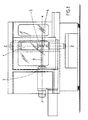
- the machine shown in FIGS. 1-4 has a rotating, stationary workpiece carrier 2, which is driven by an electric individual drive 7.
- the workpiece 3 is clamped at one end in the chuck of the workpiece carrier 2. At its other end, the workpiece 3 is held by a bearing block 8.
- the axis of rotation of workpiece carrier 2 and workpiece 3 forms the x-axis.
- the striking knives 4 are arranged on a tool carrier 5 rotating about the z-axis.
- the tool carrier 5 is clamped in a tool carrier chuck 25 at one end. With its other end, the tool carrier 5 is clamped in a bearing block 9.
- the tool holder chuck 25 is mounted in a housing 1.
- Housing 1 tool holder 5 and bearing block 9 are assigned to a tool slide 16 which can be displaced in the z direction 11.
- the tool carrier 5 is driven by an electric individual drive 6.
- the individual electric drives 6, 7 for the tool holder 5 and for the workpiece holder 2 are positively controlled by an electronic synchronizing device 13.
- the tool can be advanced in the y-direction 10 to advance the tool 4 during gear cutting work on the workpiece.
- a feed carriage 15 is provided, which can be moved by an electric drive.
- the feed carriage 15 is mounted on a drive-in carriage 14 which can also be displaced in the x direction by an electric drive 24.
- a swivel support 17 is arranged on the feed carriage 15 and can be swiveled about the y-axis running perpendicular to the x and z axes.
- the tool slide 16, which is the carrier of the tool carrier chuck 25 and the bearing block 9, is arranged in a rotationally fixed manner with the pivot carrier 17, but can also be displaced thereon in the z direction 11 by an electric drive.
- the x-axis and y-axis are skewed to one another, the z-axis being pivotable about an axis y which perpendicularly intersects both the x and z axes.
- the tool carrier 5 has several impact knives 4 which are axially separated from one another in the z direction. This makes it easy to change the flyknives used.
- the tool carriage 16 only needs to be displaced in the z direction in such a way that another fly knife 4 is brought into the use position. The position of the axes x, y, relative to one another does not change at all with this shift. Only the tool is changed.
- the tool carriage 16 can be displaced independently in the z and y directions, a supplementary tool 21 seated thereon can be advanced in the plane spanned by the y and z axes.
- the supplementary tool 21 is designed as a lathe chisel which is clamped in a clamping device 20 which is fixedly mounted on an adjusting slide 19.
- the adjustment slide 19 can be displaced longitudinally displaceably on a support block.
- the supplementary tool carrier 18, which consists of the support frame, adjusting slide 19 and tool clamping device 20, is fastened with its support frame to the housing 1 of the tool holder chuck 25 (see FIGS. 1-4) by displacing the longitudinally displaceable adjusting slide 19 in the z direction the turning tool 21 can be brought into its working position, in which it cuts the rotating workpiece 3.
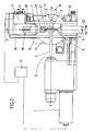
- Figures 5 and 6 show a further embodiment of the supplementary tool holder 18, which is mounted on the housing 1 of the tool holder chuck 25, as a tool changer 22, which is designed as a turret and each has four tool positions offset by 90 °, three of which have turning tools 21 are equipped.
- a tool changer 22 which is designed as a turret and each has four tool positions offset by 90 °, three of which have turning tools 21 are equipped.
- the rotation of the tool carrier 5 is stopped, the electrical drive 6 of the tool and the electrical drive 7 of the workpiece being decoupled from the synchronizing device 13.
- the electric drive 7 of the workpiece carrier 2 now runs so that the high cutting speeds required for turning can be achieved.
- the turning tool 21 is fed to the workpiece 3.
- the turning of the turning tool in the x direction takes place by moving the entry slide 14.
- a workpiece 3 toothed by means of a knife 4 can thus be deburred in a simple manner on the end faces of the toothing.
- the workpiece carrier 2, which rotates slower than the tool carrier 5 in the toothing by the number of teeth of the workpiece, is uncoupled from the positive running device 13 after the toothing, so that it can be controlled directly via the individual drive 7.
- the speed of the workpiece 3 no longer depends on the maximum speed of the tool carrier 5 and can therefore be increased in such a way that the high cutting speeds necessary for turning are achieved.
- the electric drives of feed carriage 15, entry carriage 14 and tool carriage 16 can be synchronized with the individual drive 7. Such a configuration makes it possible to rotate non-round profiles.
- the tool drive 6 is also uncoupled from the positive-running device and stands still.
- the supplementary tool will be a drill or a end mill.
- the supplementary tool can be assigned to a tool changer.
Landscapes
- Engineering & Computer Science (AREA)
- Mechanical Engineering (AREA)
- Turning (AREA)
- Machine Tool Units (AREA)
- Automatic Tool Replacement In Machine Tools (AREA)
- Electrical Discharge Machining, Electrochemical Machining, And Combined Machining (AREA)
Claims (15)
Priority Applications (1)
| Application Number | Priority Date | Filing Date | Title |
|---|---|---|---|
| AT91105712T ATE91934T1 (de) | 1990-04-26 | 1991-04-11 | Maschine zur spanenden metallbearbeitung. |
Applications Claiming Priority (2)
| Application Number | Priority Date | Filing Date | Title |
|---|---|---|---|
| DE4013327 | 1990-04-26 | ||
| DE4013327A DE4013327C2 (de) | 1990-04-26 | 1990-04-26 | Maschine zur spanenden Metallbearbeitung |
Publications (3)
| Publication Number | Publication Date |
|---|---|
| EP0453875A1 EP0453875A1 (fr) | 1991-10-30 |
| EP0453875B1 true EP0453875B1 (fr) | 1993-07-28 |
| EP0453875B2 EP0453875B2 (fr) | 2002-05-15 |
Family
ID=6405149
Family Applications (1)
| Application Number | Title | Priority Date | Filing Date |
|---|---|---|---|
| EP91105712A Expired - Lifetime EP0453875B2 (fr) | 1990-04-26 | 1991-04-11 | Machine pour le travail du métal par enlèvement de copeaux |
Country Status (4)
| Country | Link |
|---|---|
| US (1) | US5159741A (fr) |
| EP (1) | EP0453875B2 (fr) |
| AT (1) | ATE91934T1 (fr) |
| DE (2) | DE4013327C2 (fr) |
Families Citing this family (8)
| Publication number | Priority date | Publication date | Assignee | Title |
|---|---|---|---|---|
| DE4114341C2 (de) * | 1991-05-02 | 1994-04-21 | Werner Hermann Wera Werke | Maschine zur Bearbeitung umlaufender Werkstücke mittels eines in bestimmtem Drehzahlverhältnis synchron dazu umlaufenden Werkzeugs |
| DE4225509A1 (de) * | 1992-08-01 | 1994-02-03 | Werner Hermann Wera Werke | Werkzeugmaschine |
| TW301619B (fr) * | 1994-10-07 | 1997-04-01 | Toshiba Machine Co Ltd | |
| DE4446475C2 (de) * | 1994-12-23 | 2000-06-21 | Boehringer Werkzeugmaschinen | Verfahren und Maschine zum Bearbeiten von Werkstücken |
| WO1996039269A1 (fr) * | 1995-06-06 | 1996-12-12 | Widia Gmbh | Procede d'usinage par enlevement de copeaux de contours cylindriques, dispositif de mise en ×uvre du procede et plaquette de coupe associee |
| JP4113502B2 (ja) * | 2002-04-05 | 2008-07-09 | ハンス−ミハエル バイヤー, | ばり取り工具 |
| CN105817683B (zh) * | 2016-03-30 | 2018-06-22 | 上海运良转向节有限公司 | 圆槽铣刀具装置 |
| DE102017115089B4 (de) * | 2017-07-06 | 2019-04-25 | Klaus Union Gmbh & Co. Kg | Verfahren zur Herstellung eines Rotors für eine Schraubenspindelpumpe |
Family Cites Families (10)
| Publication number | Priority date | Publication date | Assignee | Title |
|---|---|---|---|---|
| US2689498A (en) * | 1950-02-06 | 1954-09-21 | Gisholt Machine Co | Rotary tool turning |
| US3803679A (en) * | 1971-05-27 | 1974-04-16 | R Eckhardt | Center maintaining rotary feeding system |
| DE2553216A1 (de) * | 1975-11-27 | 1977-06-08 | Werner Fa Hermann | Mehrkant-drehmaschine |
| DE2650955C2 (de) * | 1976-11-08 | 1985-06-27 | Hermann Werner Gmbh & Co, 5600 Wuppertal | Schlagmesser-Fräsmaschine |
| JPS5939241B2 (ja) * | 1978-12-26 | 1984-09-21 | セイコーエプソン株式会社 | 多角形加工法 |
| JPS57211419A (en) * | 1981-05-29 | 1982-12-25 | Fanuc Ltd | Numerical control machine tool |
| DE3222991A1 (de) * | 1982-06-19 | 1983-12-22 | H.Ley & M.Schmidt Ingenieurbüro für Entwicklung + Konstruktion Friedenthal, 5223 Nümbrecht | Verfahren zur herstellung von werkstuecken mit polygonaler aussen- und/oder innenkontur und vorrichtung zur durchfuehrung des verfahrens |
| CH658813A5 (de) * | 1983-04-18 | 1986-12-15 | Micafil Ag | Vorrichtung an einer nutenfraesmaschine. |
| DE3328327C2 (de) * | 1983-08-05 | 1985-10-10 | Index-Werke Kg Hahn & Tessky, 7300 Esslingen | Vorrichtung zum spanabhebenden Bearbeiten eines Werkstücks sowie NC-gesteuerte Drehmaschine zur Druchführung eines solchen Verfahrens |
| DE3843795A1 (de) * | 1988-12-24 | 1990-06-28 | Gildemeister Ag | Numerisch gesteuerte drehmaschine mit verschieblichem spindelkasten |
-
1990
- 1990-04-26 DE DE4013327A patent/DE4013327C2/de not_active Expired - Fee Related
-
1991
- 1991-04-11 AT AT91105712T patent/ATE91934T1/de not_active IP Right Cessation
- 1991-04-11 DE DE9191105712T patent/DE59100219D1/de not_active Expired - Fee Related
- 1991-04-11 EP EP91105712A patent/EP0453875B2/fr not_active Expired - Lifetime
- 1991-04-19 US US07/688,926 patent/US5159741A/en not_active Expired - Fee Related
Also Published As
| Publication number | Publication date |
|---|---|
| EP0453875B2 (fr) | 2002-05-15 |
| DE4013327A1 (de) | 1991-10-31 |
| DE59100219D1 (de) | 1993-09-02 |
| ATE91934T1 (de) | 1993-08-15 |
| DE4013327C2 (de) | 1999-12-30 |
| EP0453875A1 (fr) | 1991-10-30 |
| US5159741A (en) | 1992-11-03 |
Similar Documents
| Publication | Publication Date | Title |
|---|---|---|
| DE68909889T2 (de) | Werkzeugmaschine für mehrere bearbeitungsarten und zur komplexen bearbeitung von langen werkstücken. | |
| DE3328327C2 (de) | Vorrichtung zum spanabhebenden Bearbeiten eines Werkstücks sowie NC-gesteuerte Drehmaschine zur Druchführung eines solchen Verfahrens | |
| DE60304646T2 (de) | Mehrzweckwerkzeugmaschine und Bearbeitungsverfahren in einer Mehrzweckwerkzeugmaschine | |
| EP1418019B2 (fr) | Machine-outil avec au moins deux tourettes revolver à outils, comprenant chacune un dispositif porte-pièce | |
| EP1027955B1 (fr) | Machine-outil | |
| DE2535135C2 (fr) | ||
| EP3552743B1 (fr) | Dispositif et procédé de chanfreinage d'une pièce dentée | |
| EP3412393B1 (fr) | Dispositifs et procédé de chanfreinage d'une pièce à denture intérieure | |
| DE2739087A1 (de) | Werkzeugmaschine | |
| EP3061554A1 (fr) | Tete d'usinage pour une machine a tailler les engrenages et procede de taille d'engrenage sur une piece usinee, en particulier d'un arbre a vis sans vin ou cremaillere | |
| DE4101749A1 (de) | Fahrbare stahlrohr-fraesschneidemaschine | |
| EP3388179A1 (fr) | Procédé d'usinage de denture d'une pièce à usiner | |
| DE19806608A1 (de) | Verfahren und Vorrichtung zur fräsenden Bearbeitung von Werkstücken | |
| DE3420531C2 (de) | Drehautomat | |
| DE3237587A1 (de) | Vorrichtung zur herstellung von gewindeanschluessen an grossrohren | |
| DE19919645A1 (de) | Werkzeugmaschine mit Werkzeugspindel und Revolverkopf | |
| DE4236866A1 (de) | Drehmaschine | |
| EP0453875B1 (fr) | Machine pour le travail du métal par enlèvement de copeaux | |
| EP0360953B1 (fr) | Machine pour la finition de flancs de dents de pièces dentées | |
| EP2036638B1 (fr) | Dispositif de traitement en particulier de grands diamètres d'une pièce à usiner | |
| DE3136372A1 (de) | Doppelstaender-portalschleifmaschine | |
| DE3516100A1 (de) | Verfahren zur spanabhebenden bearbeitung von drehteilen, vorzugsweise von wellen, insbesondere von kurbelwellen, sowie vorrichtung zur durchfuehrung eines solchen verfahrens | |
| WO2006010709A1 (fr) | Machine a tailler les engrenages | |
| DE4427010C1 (de) | Maschine zum Bearbeiten der Verzahnung von Kegelrädern | |
| DE10127973C2 (de) | Vorrichtung zum Fräsen von Rastnuten und Schaltanschlägen an den Zahnflanken einzelner Zähne von Schiebemuffen für Schaltgetriebe |
Legal Events
| Date | Code | Title | Description |
|---|---|---|---|
| PUAI | Public reference made under article 153(3) epc to a published international application that has entered the european phase |
Free format text: ORIGINAL CODE: 0009012 |
|
| AK | Designated contracting states |
Kind code of ref document: A1 Designated state(s): AT BE CH DE DK ES FR GB GR IT LI LU NL SE |
|
| 17P | Request for examination filed |
Effective date: 19911114 |
|
| 17Q | First examination report despatched |
Effective date: 19921221 |
|
| GRAA | (expected) grant |
Free format text: ORIGINAL CODE: 0009210 |
|
| AK | Designated contracting states |
Kind code of ref document: B1 Designated state(s): AT BE CH DE DK ES FR GB GR IT LI LU NL SE |
|
| PG25 | Lapsed in a contracting state [announced via postgrant information from national office to epo] |
Ref country code: DK Effective date: 19930728 Ref country code: NL Effective date: 19930728 Ref country code: GR Free format text: LAPSE BECAUSE OF FAILURE TO SUBMIT A TRANSLATION OF THE DESCRIPTION OR TO PAY THE FEE WITHIN THE PRESCRIBED TIME-LIMIT Effective date: 19930728 Ref country code: BE Effective date: 19930728 Ref country code: SE Effective date: 19930728 |
|
| REF | Corresponds to: |
Ref document number: 91934 Country of ref document: AT Date of ref document: 19930815 Kind code of ref document: T |
|
| ET | Fr: translation filed | ||
| GBT | Gb: translation of ep patent filed (gb section 77(6)(a)/1977) |
Effective date: 19930727 |
|
| REF | Corresponds to: |
Ref document number: 59100219 Country of ref document: DE Date of ref document: 19930902 |
|
| ITF | It: translation for a ep patent filed | ||
| NLV1 | Nl: lapsed or annulled due to failure to fulfill the requirements of art. 29p and 29m of the patents act | ||
| PG25 | Lapsed in a contracting state [announced via postgrant information from national office to epo] |
Ref country code: AT Effective date: 19940411 |
|
| PG25 | Lapsed in a contracting state [announced via postgrant information from national office to epo] |
Ref country code: LI Effective date: 19940430 Ref country code: CH Effective date: 19940430 Ref country code: LU Free format text: LAPSE BECAUSE OF NON-PAYMENT OF DUE FEES Effective date: 19940430 |
|
| PLBI | Opposition filed |
Free format text: ORIGINAL CODE: 0009260 |
|
| 26 | Opposition filed |
Opponent name: LIEBHERR-VERZAHNTECHNIK GMBH Effective date: 19940428 |
|
| REG | Reference to a national code |
Ref country code: CH Ref legal event code: PL |
|
| RDAH | Patent revoked |
Free format text: ORIGINAL CODE: EPIDOS REVO |
|
| APAC | Appeal dossier modified |
Free format text: ORIGINAL CODE: EPIDOS NOAPO |
|
| APAE | Appeal reference modified |
Free format text: ORIGINAL CODE: EPIDOS REFNO |
|
| APAE | Appeal reference modified |
Free format text: ORIGINAL CODE: EPIDOS REFNO |
|
| PGFP | Annual fee paid to national office [announced via postgrant information from national office to epo] |
Ref country code: GB Payment date: 20010315 Year of fee payment: 11 |
|
| APAC | Appeal dossier modified |
Free format text: ORIGINAL CODE: EPIDOS NOAPO |
|
| PLAW | Interlocutory decision in opposition |
Free format text: ORIGINAL CODE: EPIDOS IDOP |
|
| REG | Reference to a national code |
Ref country code: GB Ref legal event code: IF02 |
|
| PUAH | Patent maintained in amended form |
Free format text: ORIGINAL CODE: 0009272 |
|
| STAA | Information on the status of an ep patent application or granted ep patent |
Free format text: STATUS: PATENT MAINTAINED AS AMENDED |
|
| PG25 | Lapsed in a contracting state [announced via postgrant information from national office to epo] |
Ref country code: GB Free format text: LAPSE BECAUSE OF NON-PAYMENT OF DUE FEES Effective date: 20020411 |
|
| 27A | Patent maintained in amended form |
Effective date: 20020515 |
|
| AK | Designated contracting states |
Kind code of ref document: B2 Designated state(s): AT BE CH DE DK ES FR GB GR IT LI LU NL SE |
|
| ET3 | Fr: translation filed ** decision concerning opposition | ||
| PG25 | Lapsed in a contracting state [announced via postgrant information from national office to epo] |
Ref country code: ES Free format text: LAPSE BECAUSE OF FAILURE TO SUBMIT A TRANSLATION OF THE DESCRIPTION OR TO PAY THE FEE WITHIN THE PRESCRIBED TIME-LIMIT Effective date: 20020826 |
|
| GBTA | Gb: translation of amended ep patent filed (gb section 77(6)(b)/1977) | ||
| GBPC | Gb: european patent ceased through non-payment of renewal fee |
Effective date: 20020411 |
|
| PGFP | Annual fee paid to national office [announced via postgrant information from national office to epo] |
Ref country code: FR Payment date: 20030401 Year of fee payment: 13 |
|
| PGFP | Annual fee paid to national office [announced via postgrant information from national office to epo] |
Ref country code: DE Payment date: 20030514 Year of fee payment: 13 |
|
| PG25 | Lapsed in a contracting state [announced via postgrant information from national office to epo] |
Ref country code: DE Free format text: LAPSE BECAUSE OF NON-PAYMENT OF DUE FEES Effective date: 20041103 |
|
| PG25 | Lapsed in a contracting state [announced via postgrant information from national office to epo] |
Ref country code: FR Free format text: LAPSE BECAUSE OF NON-PAYMENT OF DUE FEES Effective date: 20041231 |
|
| REG | Reference to a national code |
Ref country code: FR Ref legal event code: ST |
|
| PG25 | Lapsed in a contracting state [announced via postgrant information from national office to epo] |
Ref country code: IT Free format text: LAPSE BECAUSE OF NON-PAYMENT OF DUE FEES;WARNING: LAPSES OF ITALIAN PATENTS WITH EFFECTIVE DATE BEFORE 2007 MAY HAVE OCCURRED AT ANY TIME BEFORE 2007. THE CORRECT EFFECTIVE DATE MAY BE DIFFERENT FROM THE ONE RECORDED. Effective date: 20050411 |
|
| APAH | Appeal reference modified |
Free format text: ORIGINAL CODE: EPIDOSCREFNO |
|
| PG25 | Lapsed in a contracting state [announced via postgrant information from national office to epo] |
Ref country code: ES Free format text: LAPSE BECAUSE OF FAILURE TO SUBMIT A TRANSLATION OF THE DESCRIPTION OR TO PAY THE FEE WITHIN THE PRESCRIBED TIME-LIMIT Effective date: 19940430 |