EP3026699A1 - Anlage zum behandeln eines guts - Google Patents
Anlage zum behandeln eines guts Download PDFInfo
- Publication number
- EP3026699A1 EP3026699A1 EP15003347.0A EP15003347A EP3026699A1 EP 3026699 A1 EP3026699 A1 EP 3026699A1 EP 15003347 A EP15003347 A EP 15003347A EP 3026699 A1 EP3026699 A1 EP 3026699A1
- Authority
- EP
- European Patent Office
- Prior art keywords
- housing
- roller
- support roller
- compensating element
- installation according
- Prior art date
- Legal status (The legal status is an assumption and is not a legal conclusion. Google has not performed a legal analysis and makes no representation as to the accuracy of the status listed.)
- Granted
Links
Images


Classifications
-
- F—MECHANICAL ENGINEERING; LIGHTING; HEATING; WEAPONS; BLASTING
- F27—FURNACES; KILNS; OVENS; RETORTS
- F27B—FURNACES, KILNS, OVENS OR RETORTS IN GENERAL; OPEN SINTERING OR LIKE APPARATUS
- F27B9/00—Furnaces through which the charge is moved mechanically, e.g. of tunnel type; Similar furnaces in which the charge moves by gravity
- F27B9/14—Furnaces through which the charge is moved mechanically, e.g. of tunnel type; Similar furnaces in which the charge moves by gravity characterised by the path of the charge during treatment; characterised by the means by which the charge is moved during treatment
- F27B9/20—Furnaces through which the charge is moved mechanically, e.g. of tunnel type; Similar furnaces in which the charge moves by gravity characterised by the path of the charge during treatment; characterised by the means by which the charge is moved during treatment the charge moving in a substantially straight path
- F27B9/24—Furnaces through which the charge is moved mechanically, e.g. of tunnel type; Similar furnaces in which the charge moves by gravity characterised by the path of the charge during treatment; characterised by the means by which the charge is moved during treatment the charge moving in a substantially straight path being carried by a conveyor
- F27B9/2407—Furnaces through which the charge is moved mechanically, e.g. of tunnel type; Similar furnaces in which the charge moves by gravity characterised by the path of the charge during treatment; characterised by the means by which the charge is moved during treatment the charge moving in a substantially straight path being carried by a conveyor the conveyor being constituted by rollers (roller hearth furnace)
-
- H—ELECTRICITY
- H10—SEMICONDUCTOR DEVICES; ELECTRIC SOLID-STATE DEVICES NOT OTHERWISE PROVIDED FOR
- H10F—INORGANIC SEMICONDUCTOR DEVICES SENSITIVE TO INFRARED RADIATION, LIGHT, ELECTROMAGNETIC RADIATION OF SHORTER WAVELENGTH OR CORPUSCULAR RADIATION
- H10F71/00—Manufacture or treatment of devices covered by this subclass
-
- B—PERFORMING OPERATIONS; TRANSPORTING
- B65—CONVEYING; PACKING; STORING; HANDLING THIN OR FILAMENTARY MATERIAL
- B65G—TRANSPORT OR STORAGE DEVICES, e.g. CONVEYORS FOR LOADING OR TIPPING, SHOP CONVEYOR SYSTEMS OR PNEUMATIC TUBE CONVEYORS
- B65G39/00—Rollers, e.g. drive rollers, or arrangements thereof incorporated in roller-ways or other types of mechanical conveyors
- B65G39/02—Adaptations of individual rollers and supports therefor
-
- F—MECHANICAL ENGINEERING; LIGHTING; HEATING; WEAPONS; BLASTING
- F27—FURNACES; KILNS; OVENS; RETORTS
- F27B—FURNACES, KILNS, OVENS OR RETORTS IN GENERAL; OPEN SINTERING OR LIKE APPARATUS
- F27B9/00—Furnaces through which the charge is moved mechanically, e.g. of tunnel type; Similar furnaces in which the charge moves by gravity
- F27B9/30—Details, accessories or equipment specially adapted for furnaces of these types
-
- F—MECHANICAL ENGINEERING; LIGHTING; HEATING; WEAPONS; BLASTING
- F27—FURNACES; KILNS; OVENS; RETORTS
- F27D—DETAILS OR ACCESSORIES OF FURNACES, KILNS, OVENS OR RETORTS, IN SO FAR AS THEY ARE OF KINDS OCCURRING IN MORE THAN ONE KIND OF FURNACE
- F27D99/00—Subject matter not provided for in other groups of this subclass
- F27D99/0073—Seals
-
- H—ELECTRICITY
- H10—SEMICONDUCTOR DEVICES; ELECTRIC SOLID-STATE DEVICES NOT OTHERWISE PROVIDED FOR
- H10P—GENERIC PROCESSES OR APPARATUS FOR THE MANUFACTURE OR TREATMENT OF DEVICES COVERED BY CLASS H10
- H10P72/00—Handling or holding of wafers, substrates or devices during manufacture or treatment thereof
- H10P72/30—Handling or holding of wafers, substrates or devices during manufacture or treatment thereof for conveying, e.g. between different workstations
- H10P72/32—Handling or holding of wafers, substrates or devices during manufacture or treatment thereof for conveying, e.g. between different workstations between different workstations
- H10P72/3202—Mechanical details, e.g. rollers or belts
-
- H—ELECTRICITY
- H10—SEMICONDUCTOR DEVICES; ELECTRIC SOLID-STATE DEVICES NOT OTHERWISE PROVIDED FOR
- H10P—GENERIC PROCESSES OR APPARATUS FOR THE MANUFACTURE OR TREATMENT OF DEVICES COVERED BY CLASS H10
- H10P72/00—Handling or holding of wafers, substrates or devices during manufacture or treatment thereof
- H10P72/30—Handling or holding of wafers, substrates or devices during manufacture or treatment thereof for conveying, e.g. between different workstations
- H10P72/33—Handling or holding of wafers, substrates or devices during manufacture or treatment thereof for conveying, e.g. between different workstations into and out of processing chamber
- H10P72/3314—Continuous loading and unloading into and out of a processing chamber, e.g. transporting belts within processing chambers
-
- F—MECHANICAL ENGINEERING; LIGHTING; HEATING; WEAPONS; BLASTING
- F27—FURNACES; KILNS; OVENS; RETORTS
- F27D—DETAILS OR ACCESSORIES OF FURNACES, KILNS, OVENS OR RETORTS, IN SO FAR AS THEY ARE OF KINDS OCCURRING IN MORE THAN ONE KIND OF FURNACE
- F27D7/00—Forming, maintaining or circulating atmospheres in heating chambers
- F27D7/06—Forming or maintaining special atmospheres or vacuum within heating chambers
- F27D2007/063—Special atmospheres, e.g. high pressure atmospheres
-
- F—MECHANICAL ENGINEERING; LIGHTING; HEATING; WEAPONS; BLASTING
- F27—FURNACES; KILNS; OVENS; RETORTS
- F27M—INDEXING SCHEME RELATING TO ASPECTS OF THE CHARGES OR FURNACES, KILNS, OVENS OR RETORTS
- F27M2001/00—Composition, conformation or state of the charge
- F27M2001/15—Composition, conformation or state of the charge characterised by the form of the articles
- F27M2001/1504—Ceramic articles
-
- F—MECHANICAL ENGINEERING; LIGHTING; HEATING; WEAPONS; BLASTING
- F27—FURNACES; KILNS; OVENS; RETORTS
- F27M—INDEXING SCHEME RELATING TO ASPECTS OF THE CHARGES OR FURNACES, KILNS, OVENS OR RETORTS
- F27M2001/00—Composition, conformation or state of the charge
- F27M2001/15—Composition, conformation or state of the charge characterised by the form of the articles
- F27M2001/1539—Metallic articles
Definitions
- a furnace for the production of photovoltaic thin-film cells comprising a furnace housing, the wall of which comprises an insulating layer with a gas-tight envelope surrounding the furnace housing, in the interior of which there is a controlled atmosphere, and with a conveyor system comprising a plurality of support rollers, with the substrate plates the furnace housing are conveyable, wherein the connected to the drive means end portions of the support rollers are mounted in a bearing means, which bearing means comprises at least one bearing block, which is supported by a profiled sheet, which stands on a strut of a steel housing connected to the steel structure.
- the in the DE 10 2011 116 136 A1 described plant for the treatment of workpieces, in particular for the treatment of substrates for photovoltaic thin-film cells, has a housing which limits a treatment room in which a controlled atmosphere is present, whereby workpieces are conveyed through a conveyor system with a plurality of support rollers through the treatment room, wherein the Support rollers are mounted outside on the side wall of the housing.
- Object of the present invention is to provide a system for treating a Guts, which is further developed over the prior art, for example, in terms of disadvantages associated with the mentioned wear.
- the thermal load on the bearing device is reduced and increases their durability. Downtime of the system due to wear-related bearing changes arise, can be reduced according to the invention. Since it can be dispensed with a direct fixation of the bearing device on the housing of the system, the arrangement according to the invention enables a simpler assembly and disassembly of the transport rollers.
- the compensation element may be formed such that the at least one bearing device is decoupled from the wall of the housing with respect to the support function for the support roller.
- the wall of the housing for example a furnace side wall, can be constructed less expensively and manufactured more cheaply, e.g. due to generous manufacturing tolerances.
- the compensating element may be advantageous to arrange the compensating element in such a biased manner that the sealing arrangement is pressed in the direction of the at least one bearing device.
- an independent adjustment of the sealing arrangement is made possible, whereby wear and concentricity inaccuracies can be compensated.
- the housing may have one or more passages, which are each associated with a bearing device, wherein the compensation element between the at least one bearing device and the at least one bearing device associated wall of the housing is arranged such that despite an existing offset between the axis Support roller and the axis of the passage for the support roller by the compensation element, the seal is ensured.
- the sealing arrangement may comprise a receiving element, which is formed substantially in the form of a disc, and which extends substantially in a plane perpendicular to the axis of rotation of the support roller.
- the sealing arrangement has a sealing element which is arranged between the compensating element and the receiving element of the sealing arrangement.
- the receiving element may be provided with a groove for receiving the sealing element.
- a particularly reliable arrangement can be provided if the receiving element of the sealing arrangement is designed such that it moves in a kinematical coupling with the support roller during a movement of the support roller, in particular during a rotational movement of the support roller during conveyance of the goods.
- the compensation element may be formed substantially in the form of a tube, in which a portion of the support roller is arranged. In this way a particularly easy change of the carrying roller is made possible.
- the compensation element may be a corrugated pipe.
- the shell of the treatment space, the at least one compensation element and the at least one sealing arrangement may define an atmospheric region in which the controlled atmosphere of the shell interior is present. It may also be expedient that the shell, the at least one compensation element and the at least one sealing arrangement are gas-tight.
- At least a predominant part of the compensating element can be arranged outside the housing. It is advantageous in particular that both the compensation element and the sealing arrangement can be easily checked for condition and function.
- the compensating element is arranged in a passage of the housing.
- Such a particularly compact embodiment of the system can be made possible.
- the support roller has a roller body and a roller axle, wherein the roller body and the roller axle are positively connected with each other. In this way, the ease of maintenance of the system can be improved. A change of the support roller is simplified.
- FIGS. 1 to 7 show in various embodiments an oven provided with the reference numeral 10 as an example of a plant for the treatment of a Guts.
- Equipment for the treatment of a good can be, for example, plants for hardening, firing and / or sintering, heating or drying of goods.
- Goods may be, for example, ceramics for photovoltaics, technical ceramics, electrodes or electronic components, as well as sheets for so-called hot-stamping or composite materials.
- FIGS. 1 to 6 show the FIGS. 1 to 6 a workpiece 12, which is indicated in the drawings as a substrate in the form of a substrate plate for photovoltaic thin-film cells.
- amorphous semiconductor layers can be used, which may be less than ten microns thick.
- the workpieces 12, for example, substrates for photovoltaic thin-film cells can be treated in the furnace 10, for example, in a preferably continuous flow process. But also a clocked operated stove is possible.
- substances can be introduced into the furnace 10 or produced in the furnace 10, which are to be applied to the moving through the furnace 10 workpieces 12.
- a furnace 10 also pure thermal processes without material application, such as e.g. Annealing processes are performed.
- Equipment for the treatment of a good can be shown by way of example, can be used when a good in a treatment room 16 of the system should be treated in a different atmosphere from the normal atmosphere controlled atmosphere.
- a controlled atmosphere has parameters adapted to physical and / or chemical processes taking place in the treatment room 16.
- a controlled atmosphere may have an atmosphere with respect to normal pressure changed pressure and / or an atmosphere with a special gas, in particular a protective or an inert gas be.
- a special atmosphere may be present with comparatively high temperatures, which may be above 600 ° C., for example.
- the furnaces shown by way of example in the figures can have 10 further devices not shown in more detail, such as vacuum pumps or lines, via which a protective gas can be supplied.
- the workpieces 12 to be treated are moved by means of a conveyor system 22 through the treatment space 16.
- a conveyor system 22 By way of example, the figures show a roller of the conveyor system 22 designed as a carrier roller 24 by way of example.
- a conveyor system 22 with a carrying roller 24, as in the FIGS. 1 to 6 usually comprises a plurality of mutually parallel and spaced support rollers 24 made of a suitable, temperature-resistant material.
- a material for the support rollers 24 for example, ceramic, steel and / or silicon carbide, possibly also a silicon carbide composite ceramic can be used.
- a continuous furnace in which a material to be heated is moved by means of carrying rollers 24 through the furnace 10 is also referred to as a roller furnace.
- a drive device 44 for the carrying roller 24 is shown in each case, which can be equipped with a chain 46.
- This chain 46 may for example be formed as a solid chain and be provided in a drive mechanism, as he for example in the DE 693 34 189 T2 is described.
- the support roller 24 may also be coupled with a different kind, not shown in the figures drive device.
- an electric gear motor for such a different type of drive device, an electric gear motor, wherein the electric gear motor is coupled with the aid of a shaft assembly with the support roller 24.
- Such a shaft arrangement can, for example, similar to those in the DE 10 2009 019 127 A1 be designed shaft assembly described, wherein the shaft assembly may preferably have a king shaft.
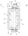
- Fig. 1 shows an oven provided with the reference numeral 10, which is described below as an example of a known per se for treating a property.
- the furnace 10 has a housing 14 defining a treatment space 16, the housing 14 comprising a layer of insulating material 18 and a gas-tight envelope 20.
- the layer with the insulating material 18 on the inside of the shell 20 is arranged.
- a material for the insulating layer for example, mineral wool can be used.
- the controlled atmosphere of the treatment space 16 is through the gas-tight envelope 20 from outside the envelope 20 present atmosphere separated, wherein the shell 20 may be made of sheet metal, for example.
- the shell 20 may be made of sheet metal, for example.
- passages 30 and 32 are provided for the support roller 24.
- roller 24 of the conveyor system 22 has a roller body 50 and a roller shaft 52, wherein the roller shaft 52 is passed through the passages 30, 32 in the side walls 26, 28 of the housing 14.
- bearing means 34 and 36 are arranged for the support roller 24 on the side walls 26, 28 on both sides of the housing 14. These bearings 34 and 36 are connected to the side walls 26 and 28 of the housing 14 and fixed to the side walls.
- An exemplary fixation of the bearing means 34, 46 on the side walls 26 and 28 is in Fig. 1 indicated.
- the roller axis 52 of the support roller 24 is mounted on both sides in areas which protrude beyond the side walls 26, 28 of the housing 14 to the outside, in the storage facilities 34 and 36.
- the arranged in the side walls 26 and 28 passages 30 and 32 for the support roller 24 are not designed gas-tight.
- the storage facilities 34, 36 for the axis of rotation 52 of the support roller 24 are also not formed gas.
- a first end region 54 of the rotation axis 52 and the associated bearing devices 34 beyond the side wall 26 are surrounded by a housing part 38 of the shell 20.
- a second end region 56 of the rotation axis 52 is coupled to the already mentioned drive device 44.
- Fig. 1 are on the second side of the oven 10 at least a part of the second end portion 56 of the axis of rotation 52 and the associated bearing means 36 beyond the side wall 28 of a housing part 40 of the shell 20 is surrounded.
- the housing parts 38, 40 of the shell 20 are designed such that a gas-tight as possible separation between the outside atmosphere and the prevailing inside the shell 20 controlled atmosphere is effected.
- a part of the second end portion 56 of the rotation axis 52 is in Fig. 1 shown example led out of the housing part 40 of the shell 20 and preferably end connected to the drive device 44.
- Fig. 1 shown arrangement which in itself corresponds to the state of the art, are the bearings 34, 36 for the support roller 24 in the prevailing inside the shell 20 controlled atmosphere, the bearings 34, 36 are exposed to high thermal stress.
- the bearing means 34 and 36 are in the prior art embodiments of a furnace 10, as in Fig. 1 indicated, fixed to the side walls 26 and 28 of the housing 14.
- an undesired inclination of the carrying roller 24 may occur.
- Such misalignment of the passages 30, 32 may occur, for example due to inaccuracies in the execution of the furnace openings.
- An inclination of the roller can cause uneven role wear and increase the wear of the support roller 24 and the wear of the bearing means 34 and 36 for the support roller 24.
- Fig. 1 shown furnace 10 is similar in its basic construction Furnaces like the example DE 10 2009 019 127 and the DE 10 2011 116 136 A1 describe, with reference to these documents reference.
- an oven generally designated by the reference numeral 10
- a workpiece 12 is treated in the surrounding of a housing 14 treatment chamber 16 of the furnace 10, wherein in the oven 10 in particular a thermal treatment can be carried out.
- the housing 14 has according to those in the FIGS. 2 to 6 shown, an insulating layer of an insulating material 18 and an outer shell 20 on.
- the shell 20 of the furnace 10 is formed at least largely gas-tight and separates the controlled atmosphere in the treatment room 16 of the plant from the surrounding atmosphere.
- a conveyor system 22 is provided with one or more support rollers 24 for the workpieces 12 to be treated.
- the in the FIGS. 2 to 6 shown support roller 24 is formed for moving the workpiece 12 through the treatment chamber 16 and coupled to the already mentioned drive device 44.
- the housing 14 of the furnace 10 has a plurality of walls. Walls of the housing 14 are e.g. a cover not provided with reference numerals and the side walls 26, 28.
- bearing means 64, 66 are provided for the carrying roller 24, wherein the bearing means 64, 66 spaced from the side walls 26, 28 of the housing 14 are arranged.
- Such storage devices 64, 66 for example, as a conventional bearing and pivot bearings, for example in the form of a rolling bearing or plain bearing formed be.
- the support roller 24 is mounted in the storage facilities 64, 66.
- Support roller 24 shown by way of example comprises a roller body 50 and a roller axle 52.
- the roller axle 52 projects beyond the roller body 52.
- the roller body 50 and the roller axle 52 are preferably connected to one another in a form-fitting manner.
- a lateral axis portion 70 of the roller axis 52 extends from the roller body 50 in the direction of the bearing device 66.
- Fig. 2 shows an embodiment of the support roller 24, in which the roller axle 52 is formed in several parts, the roller body 50 two axle sections 68, 70 of the roller shaft 52 connects.
- the roller body 50 is placed on the roller axle 52, wherein the two axle sections 68, 70 are provided with polygonal shafts 60 and 62, respectively.
- the polygon shafts 60, 62 are each formed as a hexagon.
- the diameter of the roller axis 52 is smaller than the diameter of the roller body 50.
- the diameter of the roller body 50 may be smaller than the diameter of the roller axis 52.
- Other deviating embodiments of the positive connection between roller axle 52 and roller body 50 are possible.
- one of the bearing means 66 facing side wall 28 of the housing 14 of the furnace 10 is provided with a passage 32 for the support roller 24.
- carrying roller 24 extends through passages 30, 32 of the housing 14 of the furnace 10 through and is partially disposed within and partially outside the housing 14.
- a flexible compensating element 78 is provided in the examples of FIGS. 2 to 6 is between the bearing means 66 and the side wall 28, which is associated with the bearing means 66.
- a portion of the support roller 24 is disposed in the compensation element 78 and extends through the preferably at least substantially tubular compensating element 78 therethrough.
- the roll spacings in a conveyor system 22 may be approximately equal to or greater than 75 mm.
- the compensating element 78 can be arranged in such a biased manner that the sealing arrangement 95 is pressed in the direction of the at least one bearing device 66. In this way, an automatic readjustment by means of the compensating element 78 can be made such that wear and concentricity inaccuracies are compensated. In this case, preferably, the force acting on the sealing arrangement 95 force can be adjusted.
- the flexible compensation element is in the examples of FIGS. 2 to 6 designed as a corrugated pipe. Due to its spring action, the corrugated pipe 78 can at least partially compensate for wear of the sealing arrangement 95.
- the flexibility of the compensating element 78 or its elasticity can be defined, for example, by the choice of material, structure and / or geometry.
- a sealing arrangement 95 connected to the compensating element 78 is provided.
- This sealing arrangement 95 separates the bearing device 66 from the atmosphere present inside the shell 20 or in the housing 14 of the furnace 10.
- the sealing arrangement 95 preferably has a receiving element, which is formed substantially in the form of a disc, and which extends substantially in a plane perpendicular to the axis of rotation of the support roller 24.
- a sealing mounting flange 74 is provided, wherein the mounting flange 74 in accordance with Fig. 2 is disposed between the corrugated tube 78 and the side wall 28, wherein a portion of the mounting flange 74 extends into the passage 32.
- FIGS. 2 to 6 shown embodiments of a seal of the roll feedthrough are suitable for a furnace 10 in inert gas operation with overpressure.
- the sheath 20 of the treatment chamber 16, together with the compensating element 78 and the sealing arrangement 95 and including the fastening flange 74 and the sealing element 96 defines an atmospheric region in which the controlled atmosphere of the sheath interior is present.
- the boundaries of this atmospheric region or the elements of the boundary are preferably gas-tight.
- Fig. 2 shows a sealing assembly 95 with a sealing element 86 and a thrust washer 82 as a receiving element for the sealing element 86.
- the thrust washer 82 is kinematically coupled to the support roller 24 and rotates with a rotation of the support roller 24 with this, the thrust washer 82, for example with the Roller axle 52 may be welded.
- the sealing element 86 may be annular and rubs on a movement of the support roller 24 on the thrust washer 82 and the roller shaft 52.
- the sealing element 86 is disposed between the thrust washer 82 and the corrugated tube 78, wherein an end portion of the corrugated tube 78 and a part of Sealing element 86 of a ring member 90 of the sealing assembly 95 are included.
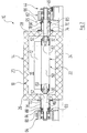
- Fig. 2 shows schematically and by way of example a furnace 10, in which beyond the two side walls 26, 28 of the furnace 10 are each a bearing means 64, 66 outside the housing 14 and at a distance from the side walls 26, 28 is arranged.
- a bearing means 64, 66 outside the housing 14 and at a distance from the side walls 26, 28 is arranged.
- on both sides of the housing 14 for example, designed as a corrugated pipe compensation element 76, 78 and a compensation element 76, 78 connected to the sealing assembly 93, 95 is provided.
- a portion of the shaft portions 68, 70 of the roller shaft 52 of the support roller 24 extends through the provided on the corresponding side of the housing corrugated tube 76 and 78.
- a preferably gas-tight seal is provided, which may be formed for example as a mounting flange 72 and 74, respectively.
- the sealing arrangement 93, 95 according to the in Fig. 2 an example of a respective associated bearing means 64, 66 shielding thrust washer 80, 82, which is connected by mediating at least one sealing element 84, 86 with the corrugated tube 76, 78, further comprising a ring member 88, 90 is provided which an end portion of the corrugated pipe 76, 78 and at least part of the sealing element 84, 86 encloses.
- the functions of supporting the carrying roller 24 and sealing the treatment chamber 16 can be separated from one another, which enables safe operation of the system, in particular at very high temperatures in the region of the passages 30, 32 for the carrier roller 24.
- the bearing devices 64, 66 are decoupled from the housing 14 of the furnace 10 with respect to the support function for the support roller 24.
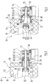
- Fig. 3 shows a furnace 10, in which the roller body 50 of the support roller 24 is shorter than the inner width of the furnace 10.
- the roller axle 52 is for positive entrainment over a Polygon shaft 62 connected to the reel body 50.
- sealing arrangement 95 has a thrust washer 94, which is equipped with a groove for receiving the sealing member 92 formed in the example shown sealing element.
- the sealing arrangement 95 also has a further ring element 90, which is arranged radially outside the sealing ring 92 and the corrugated tube 78.
- the thrust washer 94 may be clamped to the roller axle 52, using, for example, discs and / or sleeves.
- the roller body 50 of the support roller 24 of in Fig. 4 shown oven 10 is longer than the inner width of the furnace 10.
- the roller body 50 protrudes into the compensating element 78 formed in the example as a corrugated tube Fig. 4 shown thrust washer 100 of the seal assembly 95 has a plurality of drive pins 106 which project into the support roller 24.
- the bottom 98 of the roller body 50 may be provided with bores for receiving the driving pins 106.
- the thrust washer 100 further has a groove for receiving the sealing ring 92 of the sealing assembly 95, wherein a further annular element 90 is provided which comprises a part of the sealing ring 92 and a part of the corrugated tube 78.
- Fig. 4 an offset between the axis of the support roller and the axis of the provided in the side wall 28 passage 32 for the support roller 24 can be seen.
- This offset can be compensated by the compensation element 78.
- the corrugated tube 78 is aligned in the example shown deviating from a horizontal axis, wherein the corrugated tube 78 is oriented from the wall of the housing 14 to the bearing device 66 in ascending order. Due to the flexible alignment of the compensating element 78 designed as a corrugated pipe, the seal is ensured despite an existing offset between the axis of the support roller 24 and the axis of the passage 32.
- the compensating element 78 is disposed outside of the housing 14.
- the fastening flange 74 provided between the corrugated tube 78 and the side wall 28 is preferably arranged largely outside the passage 32.
- a sealing element 96 is provided on the side wall 28, which is arranged between the compensating element 78 formed as a corrugated tube 78 and the side wall 28, wherein the sealing element 96 is drawn into the passage 32 of the side wall 28 or preferably to a essential part is disposed within the passage 32.
- sealing arrangements 95 have, similar to the previously described sealing arrangements 95, a sealing ring 92, an outer ring member and a thrust washer 94 with a groove for receiving the sealing ring 92.
- the roller axle 52 of the support roller 24 is positively connected to the roller body 54 by means of a polygonal shaft 62.
- the roller axle 52 of the support roller 24 is provided with a collar 104.
- the roller axle is connected to the roller body 54 via, for example, the collar 104 arranged driver 102.
- the drivers 102 are pin-shaped in the example shown and protrude into the bottom 98 of the roller body 54. Such a configuration may be particularly advantageous for large roles.
- the diameter of the passage 32 and the diameter of the corrugated pipe 78 are usually matched to the size of the support roller 24 used.
- FIGS. 2 to 6 explained exemplary embodiments of the invention are suitable for a system with very high temperatures in the treatment room 16, wherein material selection and design can be adapted to the specific conditions of use.
- One of the advantages of these embodiments is that, in particular, the sealing surfaces that are essential for operation are arranged in a manner that is easier to access and can therefore be controlled relatively simply for their condition and function.
- Another advantage is that the bearings of the storage facilities 64, 66 are better protected from the above high temperatures.
- the present invention relates to a system designed for example as a roller furnace for treating a product, having a treatment space 16 provided with a shell 20 having an atmosphere present in its interior separates from an atmosphere present outside the envelope 20, wherein the atmosphere present within the envelope 20 is a controlled atmosphere, with a housing 14 having walls and bounding the treatment space 16 with at least one support roller 24 at least partially disposed within the treatment space 16 Conveying the Guts, and with one or more storage devices 64, 66 which are arranged outside the walls of the housing 14, and in which the at least one support roller 24 is mounted, wherein between at least one bearing means 64, 66 and a wall of the housing associated therewith 14 a flexible A is provided us stressesselement 78, wherein a connected to the compensating element 78 sealing assembly 93, 95 is provided, which the at least one storage device 64, 66 separates from the atmosphere within the envelope 20. In this way, the load on the storage devices 64, 66 can be reduced and their service
- FIG. 7 is shown in an enlarged detail a modified sealing arrangement 95, wherein already explained components carry the same reference numerals.
- the sealing assembly 95 is formed as a floating seal 108, in which a sealing ring 110 is arranged floating between a thrust washer 112 on the bearing device 66 and a ring member 114 on the compensating element 78.
- the sealing ring 110 has a circular cross-section and its outer circumferential surface 116 bears sealingly against a sealing surface 118 of the thrust washer 112 and against a sealing surface 120 of the annular element 114.
- these sealing surfaces 118 and 120 are curved and have a circular arc in the present embodiment in cross-section.
- the floating seal 110 ensures that the seal is maintained even with a change in position of the compensating element 78, since the components involved can follow a bearing change, without that by the curved surfaces 112, 118, 120 linear sealing contact is interrupted.
- the sealing ring 110 may also have a different cross-section from a circle, in particular a rectangular or square cross-section. Due to the curved mating surfaces 118, 120 a sealing contact with the thrust washer 112 and the ring member 114 is always ensured.
Landscapes
- Engineering & Computer Science (AREA)
- Mechanical Engineering (AREA)
- General Engineering & Computer Science (AREA)
- Tunnel Furnaces (AREA)
- Furnace Details (AREA)
- Rollers For Roller Conveyors For Transfer (AREA)
- Manufacturing & Machinery (AREA)
- Chemical Vapour Deposition (AREA)
Abstract
Description
- Die Erfindung betrifft eine Anlage zum Behandeln eines Guts mit
- a) einem Behandlungsraum, der mit einer Hülle ausgestattet ist, welche eine innerhalb der Hülle vorliegende Atmosphäre von einer außerhalb der Hülle vorliegenden Atmosphäre trennt, wobei die innerhalb der Hülle vorliegende Atmosphäre eine kontrollierte Atmosphäre ist;
- b) einem Gehäuse, welches den Behandlungsraum begrenzt;
- c) mindestens einer zumindest teilweise innerhalb des Behandlungsraums angeordneten Tragrolle zum Fördern des Guts;
- d) einer oder mehreren Lagereinrichtungen, welche außerhalb des Gehäuses angeordnet sind und mittels welchen die mindestens eine Tragrolle gelagert ist.
- Aus der
DE 10 2009 019 127 A1 ist ein Ofen zur Herstellung von photovoltaischen Dünnschichtzellen bekannt, mit einem Ofengehäuse, dessen Wand eine Isolierschicht umfasst, mit einer das Ofengehäuse umgebenden gasdichten Hülle, in deren Innenraum eine kontrollierte Atmosphäre vorliegt, und mit einem eine Vielzahl von Tragrollen umfassenden Fördersystem, mit dem Substratplatten durch das Ofengehäuse förderbar sind, wobei die mit der Antriebseinrichtung verbundenen Endbereiche der Tragrollen in einer Lagereinrichtung gelagert sind, welche Lagereinrichtung mindestens einen Lagerbock umfasst, der durch ein Profilblech getragen wird, welches auf einer Strebe eines mit dem Ofengehäuse verbundenen Stahlbaus steht. - Die in der
DE 10 2011 116 136 A1 beschriebene Anlage zur Behandlung von Werkstücken, insbesondere zur Behandlung von Substraten für photovoltaische Dünnschichtzellen, hat ein Gehäuse, welches einen Behandlungsraum begrenzt, in dem eine kontrollierte Atmosphäre vorliegt, wobei Werkstücke durch ein Fördersystem mit einer Vielzahl von Tragrollen durch den Behandlungsraum förderbar sind, wobei die Tragrollen außen an der Seitenwand des Gehäuses gelagert sind. - Bei bekannten Anlagen unterliegen insbesondere die Tragrollen und die Lagereinrichtungen für die Tragrollen einem verhältnismäßig hohen Verschleiß.
- Aufgabe der vorliegenden Erfindung ist es, eine Anlage zur Behandeln eines Guts bereitzustellen, die gegenüber dem Stand der Technik, beispielsweise im Hinblick auf Nachteile, die mit dem angesprochenen Verschleiß zusammenhängen, weiterentwickelt ist.
- Diese Aufgabe wird bei einer Anlage der eingangs genannten Art, dadurch gelöst, dass
- e) zwischen mindestens einer Lagereinrichtung und einer der Lagereinrichtung zugeordneten Wand des Gehäuses ein flexibles Ausgleichselement vorgesehen ist;
- f) eine mit dem Ausgleichselement verbundene Dichtanordnung vorgesehen ist, welche die mindestens eine Lagereinrichtung von der innerhalb der Hülle vorliegenden Atmosphäre trennt.
- Auf diese Weise wird die thermische Belastung der Lagereinrichtung gemindert und ihre Haltbarkeit erhöht. Ausfallzeiten der Anlage, die durch verschleißbedingte Lagerwechsel entstehen, können erfindungsgemäß reduziert werden. Da auf eine direkte Fixierung der Lagereinrichtung am Gehäuse der Anlage verzichtet werden kann, ermöglicht die erfindungsgemäße Anordnung eine einfachere Montage und Demontage der Transportrollen.
- Vorzugsweise kann das Ausgleichselement derart ausgebildet sein, dass die mindestens eine Lagereinrichtung hinsichtlich der Tragfunktion für die Tragrolle von der Wand des Gehäuses entkoppelt ist. Somit kann die Wand des Gehäuses, beispielsweise eine Ofenseitenwand, weniger aufwendig konstruiert und kostengünstiger gefertigt werden, z.B. auf Grund großzügiger Fertigungstoleranzen.
- Es kann vorteilhaft sein, das Ausgleichselement derart vorgespannt anzuordnen, dass die Dichtanordnung in Richtung der mindestens einen Lagereinrichtung gepresst wird. Derart wird ein selbstständiges Nachstellen der Dichtanordnung ermöglicht, wodurch Verschleiß und Rundlaufungenauigkeiten ausgeglichen werden können.
- In zweckmäßiger Ausgestaltung kann das Gehäuse ein oder mehrere Durchgänge aufweisen, die jeweils einer Lagereinrichtung zugeordnet sind, wobei das Ausgleichselement derart zwischen der mindestens einen Lagereinrichtung und der dieser mindestens einen Lagereinrichtung zugeordneten Wand des Gehäuses angeordnet ist, dass trotz eines bestehenden Versatzes zwischen der Achse der Tragrolle und der Achse des Durchgangs für die Tragrolle durch das Ausgleichselement die Abdichtung gewährleistet ist. Derart können Fluchtungsfehler der Durchgänge des Gehäuses unter Vermittlung des Ausgleichselements kompensiert werden. Somit kann der Verschleiß, insbesondere ein durch eine Schrägstellung der Tragrolle bedingter Verschleiß, reduziert werden. Vorzugsweise kann die Dichtanordnung ein Aufnahmeelement aufweisen, welches im Wesentlichen in Form einer Scheibe ausgebildet ist, und welches sich im Wesentlichen in einer Ebene senkrecht zur Drehachse der Tragrolle erstreckt. Das Vorsehen eines derart ausgebildeten Aufnahmeelements kann gerade beim Einsatz für eine Anlage, welche für einen Schutzgasbetrieb im Überdruck ausgelegt ist, günstig sein.
- Es kann beispielsweise zur Beaufschlagung mit Sperrgas von Vorteil sein, wenn die Dichtanordnung ein Dichtelement aufweist, welches zwischen dem Ausgleichselement und dem Aufnahmeelement der Dichtanordnung angeordnet ist. Dabei kann das Aufnahmeelement mit einer Nut zur Aufnahme des Dichtelements versehen sein.
- Eine besonders betriebssichere Anordnung kann bereitgestellt werden, wenn das Aufnahmeelement der Dichtanordnung derart ausgebildet ist, dass es sich bei einer Bewegung der Tragrolle, insbesondere bei einer Drehbewegung der Tragrolle beim Fördern des Guts, in kinematischer Kopplung mit der Tragrolle bewegt.
- Mit Vorteil kann das Ausgleichselement im Wesentlichen in Form eines Rohrs ausgebildet sein, in welchem ein Teilbereich der Tragrolle angeordnet ist. Derart wird ein besonders leichter Wechsel der Tragrolle ermöglicht.
- In weiter vorteilhafter Ausgestaltung kann das Ausgleichselement ein Wellrohr sein.
- Vorzugsweise können die Hülle des Behandlungsraums, das mindestens eine Ausgleichselement und die mindestens eine Dichtanordnung einen atmosphärischen Bereich begrenzen, in dem die kontrollierte Atmosphäre des Hülleninneren vorliegt. Es kann weiterhin zweckmäßig sein, dass die Hülle, das mindestens eine Ausgleichselement und die mindestens eine Dichtanordnung gasdicht ausgebildet sind.
- Vorzugsweise kann zumindest ein überwiegender Teil des Ausgleichselements außerhalb des Gehäuses angeordnet sein. Vorteilhaft ist hierbei insbesondere, dass sowohl das Ausgleichselement als auch die Dichtanordnung leicht auf Zustand und Funktion kontrolliert werden können.
- Beispielsweise bei beengten Raumvorgaben kann es zweckmäßig sein, wenn zumindest ein Teil des Ausgleichselements in einem Durchgang des Gehäuses angeordnet ist. Derart kann eine besonders kompakte Ausführungsform der Anlage ermöglicht werden.
- In weiterer Ausgestaltung weist die Tragrolle einen Rollenkörper und eine Rollenachse auf, wobei der Rollenkörper und die Rollenachse formschlüssig miteinander verbunden sind. Auf diese Weise kann die Wartungsfreundlichkeit der Anlage verbessert werden. Ein Wechsel der Tragrolle wird dabei vereinfacht.
- Vorzugsweise erstreckt sich die Tragrolle senkrecht zu zwei Seitenwänden des Gehäuses, wobei jenseits der zwei Seitenwände und von den zwei Seitenwänden beabstandet angeordnet jeweils eine Lagereinrichtung mit einem zugehörigen Ausgleichselement und einer zugehörigen Dichtanordnung vorgesehen ist, wobei die Tragrolle in den beiden Lagereinrichtungen gelagert ist. Derart werden beide Lagereinrichtungen thermisch weniger belastet. Die Lebensdauer der Lagereinrichtungen wird erhöht. Weiterhin kann beispielsweise vermieden werden, dass die häufig mit Lagerfett versehenen Lager der Lagereinrichtungen in Kontakt mit einer Atmosphäre kommen, die vergleichsweise hohe Temperaturen aufweist. Weitere vorteilhafte Ausgestaltungen ergeben sich aus der nachfolgenden Beschreibung. Dabei werden Ausführungsbeispiele der Erfindung, ohne hierauf beschränkt zu sein, an Hand der Zeichnungen näher erläutert. Es zeigt, jeweils in vereinfachter, schematischer Darstellung:
- Figur 1
- einen vertikalen Schnitt durch eine Anlage zur Behandlung eines Guts mit einem an und für sich bekannten Ofen gemäß dem Stand der Technik;
- Figur 2
- einen vertikalen Schnitt durch eine Anlage zur Behandlung eines Guts gemäß einem Beispiel der vorliegenden Erfindung;
- Figur 3
- in Detailvergrößerung einen vertikalen Schnitt durch eine Anlage zur Behandlung eines Guts gemäß einem weiteren Beispiel der vorliegenden Erfindung;
- Figur 4
- ein weiteres Beispiel der Erfindung in einer
Figur 3 entsprechenden Ansicht; - Figur 5
- ein weiteres Beispiel der Erfindung in einer
Figur 3 entsprechenden Ansicht; - Figur 6
- ein weiteres Beispiel der Erfindung in einer
Figur 3 entsprechenden Ansicht. - Figur 7
- eine Detailvergrößerung einer abgewandelten Dichtanordnung.
- Die
Figuren 1 bis 7 zeigen in unterschiedlichen Ausgestaltungen einen insgesamt mit dem Bezugszeichen 10 versehenen Ofen als Beispiel für eine Anlage zur Behandlung eines Guts. Anlagen zur Behandlung eines Guts können beispielsweise Anlagen zum Härten, Brennen und/oder Sintern, Aufheizen oder Trocknen von Gütern sein. Dabei können Güter beispielsweise Keramiken für die Photovoltaik, technische Keramiken, Elektroden oder elektronische Bauelemente sowie Bleche für das so genannte Hot-Stamping oder Verbundmaterialien sein. - Als Beispiel für ein Gut, welches in einem Behandlungsraum 16 der Anlage behandelt wird, zeigen die
Figuren 1 bis 6 ein Werkstück 12, das in den Zeichnungen als Substrat in Form einer Substratplatte für photovoltaische Dünnschichtzellen angedeutet ist. Bei derartigen photovoltaischen Dünnschichtzellen können amorphe Halbleiterschichten zur Anwendung kommen, die weniger als zehn Mikron dick sein können. Die Werkstücke 12, z.B. Substrate für photovoltaische Dünnschichtzellen, können beispielsweise in einem vorzugsweise kontinuierlichen Durchlaufverfahren im Ofen 10 behandelt werden. Aber auch ein getaktet betriebener Ofen ist möglich. - Mittels nicht näher dargestellter Einrichtungen können Substanzen in den Ofen 10 eingebracht oder im Ofen 10 erzeugt werden, die auf die durch den Ofen 10 bewegten Werkstücke 12 aufgebracht werden sollen. In einem Ofen 10 können auch reine thermische Prozesse ohne Materialaufbringung, wie z.B. Glühprozesse, durchgeführt werden.
- Anlagen zur Behandlung eines Guts, wie sie in den
Figuren 1 bis 6 beispielhaft gezeigt werden, können dann eingesetzt werden, wenn ein Gut in einem Behandlungsraum 16 der Anlage in einer von der Normalatmosphäre abweichenden kontrollierten Atmosphäre behandelt werden soll. Eine derartige kontrollierte Atmosphäre weist Parameter auf, die an physikalische und/oder chemische Vorgänge angepasst sind, die in dem Behandlungsraum 16 stattfindenden. Eine kontrollierte Atmosphäre kann z.B. eine Atmosphäre mit gegenüber dem Normaldruck verändertem Druck und/oder eine Atmosphäre mit einem besonderen Gas, insbesondere einem Schutz- oder einem Inertgas, sein. In einer kontrollierten Atmosphäre werden z.B. photovoltaische Zellen hergestellt. In den gezeigten Öfen 10 kann beispielsweise eine Sonderatmosphäre vorliegen mit vergleichsweise hohen Temperaturen, die z.B. über 600°C liegen können. - Zur Erzeugung einer innerhalb des Ofens 10 gewünschten kontrollierten Atmosphäre können die beispielhaft in den Figuren gezeigten Öfen 10 weitere nicht näher dargestellte Einrichtungen aufweisen, wie beispielsweise Vakuumpumpen oder Leitungen, über welche ein Schutzgas zugeführt werden kann.
- Die zu behandelnden Werkstücke 12 werden mit Hilfe eines Fördersystems 22 durch den Behandlungsraum 16 bewegt. Die Figuren zeigen beispielhaft jeweils eine als Tragrolle 24 ausgebildete Rolle des Fördersystems 22.
- Ein Fördersystem 22 mit einer Tragrolle 24, wie sie in den
Figuren 1 bis 6 gezeigt wird, umfasst in der Regel eine Vielzahl von parallel zueinander und in Abstand voneinander angeordneten Tragrollen 24 aus einem geeigneten, temperaturbeständigen Material. Als Material für die Tragrollen 24 kann beispielsweise Keramik, Stahl und/oder Siliziumcarbid, ggf. auch eine Siliziumcarbid-Verbundkeramik, verwendet werden. Ein Durchlaufofen, in dem ein zu beheizendes Gut mittels Tragrollen 24 durch den Ofen 10 bewegt wird, wird auch als Rollenofen bezeichnet. - In den
Figuren 1 bis 6 ist jeweils beispielhaft eine Antriebsvorrichtung 44 für die Tragrolle 24 gezeigt, welche mit einer Kette 46 ausgestattet sein kann. Diese Kette 46 kann beispielsweise als durchgezogene Kette ausgebildet sein und in einem Antriebsmechanismus vorgesehen sein, wie er beispielsweise in derDE 693 34 189 T2 beschrieben wird. Die Tragrolle 24 kann auch mit einer anders gearteten, in den Figuren nicht näher dargestellten Antriebsvorrichtung gekoppelt sein. So kann beispielsweise als Antriebsquelle für eine derartige anders geartete Antriebsvorrichtung ein Elektrogetriebemotor vorgesehen sein, wobei der Elektrogetriebemotor unter Zuhilfenahme einer Wellenanordnung mit der Tragrolle 24 gekoppelt ist. Eine derartige Wellenanordnung kann z.B. ähnlich der in derDE 10 2009 019 127 A1 beschriebenen Wellenanordnung ausgestaltet sein, wobei die Wellenanordnung vorzugsweise eine Königswelle aufweisen kann. In weiterhin alternativer Ausgestaltung ist es z.B. möglich, dass ein oder mehrere Tragrollen 24 einer Anlage zur Behandlung eines Guts ohne korrespondierende Antriebsvorrichtung vorgesehen sind. Alternativ oder zusätzlich ist es möglich ein oder mehrere Tragrollen 24 jeweils mit einem Direktantrieb auszustatten. -
Fig. 1 zeigt einen insgesamt mit dem Bezugszeichen 10 versehenen Ofen, der nachfolgend als Beispiel für eine an und für sich bekannte Anlage zur Behandlung eines Guts beschrieben wird. - Der Ofen 10 weist ein Gehäuse 14 auf, welches einen Behandlungsraum 16 begrenzt, wobei das Gehäuse 14 eine Schicht mit einem Isoliermaterial 18 und eine gasdichte Hülle 20 umfasst. Im Beispiel ist die Schicht mit dem Isoliermaterial 18 innenseitig der Hülle 20 angeordnet. Als Material für die Isolierschicht kann beispielsweise Mineralwolle eingesetzt werden.
- In dem Behandlungsraum 16 der als Ofen ausgebildeten Anlage herrscht die vorangehend angesprochene kontrollierte Atmosphäre. Die kontrollierte Atmosphäre des Behandlungsraums 16 wird durch die gasdichte Hülle 20 von der außerhalb der Hülle 20 vorliegenden Atmosphäre getrennt, wobei die Hülle 20 beispielsweise aus Blech gefertigt sein kann. In den Seitenwänden 26 und 28 des Gehäuses 14 sind Durchgänge 30 bzw. 32 für die Tragrolle 24 vorgesehen.
- Die in
Fig. 1 gezeigte Tragrolle 24 des Fördersystems 22 weist einen Rollenkörper 50 und eine Rollenachse 52 auf, wobei die Rollenachse 52 durch die Durchgänge 30, 32 in den Seitenwänden 26, 28 des Gehäuses 14 hindurchgeführt ist. Außerhalb des Gehäuses 14 sind an den Seitenwänden 26, 28 beidseitig des Gehäuses 14 Lagereinrichtungen 34 bzw. 36 für die Tragrolle 24 angeordnet. Diese Lagereinrichtungen 34 und 36 sind mit den Seitenwänden 26 bzw. 28 des Gehäuses 14 verbunden und an den Seitenwänden festgelegt. Eine beispielhafte Fixierung der Lagereinrichtungen 34, 46 an den Seitenwänden 26 bzw. 28 ist inFig. 1 angedeutet. - Die Rollenachse 52 der Tragrolle 24 ist beidseitig in Bereichen, die über die Seitenwände 26, 28 des Gehäuses 14 nach außen vorstehen, in den Lagereinrichtungen 34 und 36 gelagert. Die in den Seitenwänden 26 und 28 angeordneten Durchgänge 30 bzw. 32 für die Tragrolle 24 sind nicht gasdicht ausgeführt. Die Lagereinrichtungen 34, 36 für die Drehachse 52 der Tragrolle 24 sind ebenfalls nicht Gas nicht ausgebildet.
- Auf einer ersten Seite des Ofens 14 sind ein erster Endbereich 54 der Drehachse 52 und die zugeordnete Lagereinrichtungen 34 jenseits der Seitenwand 26 von einem Gehäuseteil 38 der Hülle 20 umgeben.
- Auf einer zweiten Seite des Ofens 14, welche der ersten Seite gegenüberliegt, ist ein zweiter Endbereich 56 der Drehachse 52 mit der bereits erwähnten Antriebsvorrichtung 44 gekoppelt. Gemäß
Fig. 1 sind auf der zweiten Seite des Ofens 10 zumindest ein Teil des zweiten Endbereichs 56 der Drehachse 52 und die zugeordnete Lagereinrichtungen 36 jenseits der Seitenwand 28 von einer Gehäuseteil 40 der Hülle 20 umgeben. Die Gehäuseteile 38, 40 der Hülle 20 sind derart ausgebildet, dass eine möglichst gasdichte Trennung zwischen der Außenatmosphäre und der im Inneren der Hülle 20 herrschenden kontrollierten Atmosphäre bewirkt wird. Ein Teil des zweiten Endbereichs 56 der Drehachse 52 ist inFig. 1 gezeigten Beispiel aus der Gehäuseteil 40 der Hülle 20 herausgeführt und vorzugsweise endseitig mit der Antriebsvorrichtung 44 verbunden. - Entsprechend der in
Fig. 1 gezeigten Anordnung, die an und für sich dem Stand der Technik entspricht, befinden sich die Lagereinrichtungen 34, 36 für die Tragrolle 24 in der im Inneren der Hülle 20 herrschenden kontrollierten Atmosphäre, wobei die Lagereinrichtungen 34, 36 einer hohen thermischen Belastung ausgesetzt sind. - Wie bereits erwähnt sind die Lagereinrichtungen 34 und 36 in dem Stand der Technik entsprechenden Ausführungen eines Ofens 10, wie in der
Fig. 1 angedeutet, an den Seitenwänden 26 bzw. 28 des Gehäuses 14 fixiert. Dadurch bedingt kann es auf Grund von in der Praxis nicht immer vermeidbaren Fluchtungsfehlern der Durchgänge 30, 32 in den Seitenwänden 26 bzw. 28 des Gehäuses 14 zu einer unerwünschten Schrägstellung der Tragrolle 24 kommen. Derartige Fluchtungsfehler der Durchgänge 30, 32 können beispielsweise bedingt durch Ungenauigkeiten bei der Ausführung der Ofendurchbrüche auftreten. Eine Schrägstellung der Rolle kann eine ungleichmäßige Rollenabnutzung bedingen und den Verschleiß der Tragrolle 24 bzw. den Verschleiß der Lagereinrichtungen 34 und 36 für die Tragrolle 24 erhöhen. - Der in
Fig. 1 gezeigte Ofen 10 ähnelt in seinem Grundaufbau Öfen wie sie beispielsweise dieDE 10 2009 019 127 und dieDE 10 2011 116 136 A1 beschreiben, wobei auf diese Druckschriften ergänzend Bezug genommen wird. - Anhand der
Figuren 2 bis 6 werden nachfolgend verschiedene Beispiele der vorliegenden Erfindung beschrieben, wobei ein insgesamt mit dem Bezugszeichen 10 versehener Ofen als Beispiel für eine Anlage zur Behandlung eines Guts beschrieben wird. Dabei wird ein Werkstück 12 in dem von einem Gehäuse 14 umgebenen Behandlungsraum 16 des Ofens 10 behandelt, wobei in dem Ofen 10 insbesondere eine thermische Behandlung erfolgen kann. Das Gehäuse 14 weist gemäß den in denFiguren 2 bis 6 gezeigten Beispielen eine Isolierschicht aus einem Isoliermaterial 18 und eine äußere Hülle 20 auf. Die Hülle 20 des Ofens 10 ist zumindest weitestgehend gasdicht ausgebildet und trennt die kontrollierte Atmosphäre im Behandlungsraum 16 der Anlage von der umgebenden Atmosphäre. - Wie in
Fig. 2 angedeutet ist im Behandlungsraum 16 ein Fördersystems 22 mit ein oder mehreren Tragrollen 24 für die zu behandelnden Werkstücke 12 vorgesehen. Die in denFiguren 2 bis 6 gezeigte Tragrolle 24 ist zum Bewegen des Werkstücks 12 durch den Behandlungsraum 16 ausgebildet und mit der bereits erwähnten Antriebsvorrichtung 44 gekoppelt. - Das Gehäuse 14 des Ofens 10 weist mehrere Wände auf. Wände des Gehäuses 14 sind z.B. eine nicht mit Bezugszeichen versehene Decke und die Seitenwände 26, 28.
- Außerhalb des Gehäuses 14 sind Lagereinrichtungen 64, 66 für die Tragrolle 24 vorgesehen, wobei die Lagereinrichtungen 64, 66 beabstandet von den Seitenwände 26, 28 des Gehäuses 14 angeordnet sind. Derartige Lagereinrichtungen 64, 66 können beispielsweise als herkömmliche Trag- und Drehlager, z.B. in Form eines Wälzlagers oder Gleitlagers, ausgebildet sein. Die Tragrolle 24 ist in den Lagereinrichtungen 64, 66 gelagert.
- Die in den
Figuren 2 bis 6 beispielhaft gezeigte Tragrolle 24 weist einen Rollenkörper 50 und eine Rollenachse 52 auf. In den gezeigten Beispielen ragt die Rollenachse 52 über den Rollenkörper 52 hinaus. Der Rollenkörper 50 und die Rollenachse 52 sind vorzugsweise formschlüssig miteinander verbunden. Ein seitlicher Achsabschnitt 70 der Rollenachse 52 erstreckt sich vom Rollenkörper 50 in Richtung der Lagereinrichtung 66. -
Fig. 2 zeigt eine Ausgestaltung der Tragrolle 24, bei der die Rollenachse 52 mehrteilig ausgebildet ist, wobei der Rollenkörper 50 zwei Achsabschnitte 68, 70 der Rollenachse 52 verbindet. Im gezeigten Beispiel ist der Rollenkörper 50 auf die Rollenachse 52 gesteckt, wobei die zwei Achsabschnitte 68, 70 mit Polygonwellen 60 bzw. 62 versehen sind. Im gezeigten Beispiel sind die Polygonwellen 60, 62 jeweils als Sechskant ausgebildet. Im gezeigten Beispiel ist der Durchmesser der Rollenachse 52 kleiner als der Durchmesser des Rollenkörpers 50. In einer in den Figuren nicht gezeigten, abweichenden Ausgestaltung der Tragrolle 24 kann der Durchmesser des Rollenkörpers 50 kleiner sein als der Durchmesser der Rollenachse 52. Weitere abweichende Ausgestaltungen des Formschlusses zwischen Rollenachse 52 und Rollenkörper 50 sind möglich. - Gemäß den in den
Figuren 2 bis 6 gezeigten Beispielen ist eine der Lagereinrichtung 66 zugewandte Seitenwand 28 des Gehäuses 14 des Ofens 10 mit einem Durchgang 32 für die Tragrolle 24 versehen. Die inFig. 2 gezeigte Tragrolle 24 erstreckt sich durch Durchgänge 30, 32 des Gehäuses 14 des Ofens 10 hindurch und ist teilweise innerhalb und teilweise außerhalb des Gehäuses 14 angeordnet. - In den Beispielen der
Figuren 2 bis 6 ist zwischen der Lagereinrichtung 66 und der Seitenwand 28, welche der Lagereinrichtung 66 zugeordnet ist, ein flexibles Ausgleichselement 78 vorgesehen. Ein Teilbereich der Tragrolle 24 ist in dem Ausgleichselement 78 angeordnet bzw. erstreckt sich durch das vorzugsweise zumindest im Wesentlichen rohrförmig ausgebildete Ausgleichselement 78 hindurch. Derart ist ein leichter Wechsel einzelner Ofenrollen, z.B. der Tragrollen 24 eines Fördersystems 22 (sieheFig. 2 ), möglich. Die Rollenabstände in einem Fördersystem 22 können beispielsweise ungefähr gleich oder größer 75 mm sein. - Das Ausgleichselement 78 kann derart vorgespannt angeordnet werden, dass die Dichtanordnung 95 in Richtung der mindestens einen Lagereinrichtung 66 gepresst wird. Auf diese Weise kann ein automatisches Nachstellen mittels des Ausgleichselements 78 derart erfolgen, dass Verschleiß und Rundlaufungenauigkeiten ausgeglichen werden. Dabei kann vorzugsweise die auf die Dichtanordnung 95 wirkende Kraft eingestellt werden. Das flexible Ausgleichselement ist in den Beispielen der
Figuren 2 bis 6 als Wellrohr ausgebildet. Durch seine Federwirkung kann das Wellrohr 78 Abnutzungen der Dichtanordnung 95 zumindest teilweise kompensieren. Grundsätzlich kann die Flexibilität des Ausgleichselements 78 bzw. seine Elastizität beispielsweise durch Wahl von Material, Struktur und/oder Geometrie definiert werden. - Weiterhin ist in den Beispielen der
Figuren 2 bis 6 eine mit dem Ausgleichselement 78 verbundene Dichtanordnung 95 vorgesehen. Diese Dichtanordnung 95 trennt die Lagereinrichtung 66 von der innerhalb der Hülle 20 bzw. im Gehäuse 14 des Ofens 10 vorliegenden Atmosphäre. Dazu weist die Dichtanordnung 95 vorzugsweise ein Aufnahmeelement auf, welches im Wesentlichen in Form einer Scheibe ausgebildet ist, und welches sich im Wesentlichen in einer Ebene senkrecht zur Drehachse der Tragrolle 24 erstreckt. - Auf der dem Gehäuse 14 zugewandten Seite des beispielsweise als Wellrohr 78 ausgebildeten Ausgleichselements 78 ist ein dichtender Befestigungsflansch 74 vorgesehen, wobei der Befestigungsflansch 74 gemäß
Fig. 2 zwischen dem Wellrohr 78 und der Seitenwand 28 angeordnet ist, wobei sich ein Teil des Befestigungsflanschs 74 in den Durchgang 32 erstreckt. - Die in den Beispielen der
Figuren 2 bis 6 gezeigten Ausgestaltungen einer Abdichtung der Rollendurchführung sind für einen Ofen 10 im Schutzgasbetrieb mit Überdruck geeignet. Dabei begrenzt die Hülle 20 des Behandlungsraums 16 gemeinsam mit dem Ausgleichselement 78 und der Dichtanordnung 95 und unter Einbeziehung des Befestigungsflanschs 74 bzw. des Dichtelements 96 einen atmosphärischen Bereich, in dem die kontrollierte Atmosphäre des Hülleninneren vorliegt. Die Begrenzungen dieses atmosphärischen Bereichs bzw. die Elemente der Begrenzung sind dabei vorzugsweise gasdicht ausgebildet. -
Fig. 2 zeigt eine Dichtanordnung 95 mit einem Dichtelement 86 und mit einer Anlaufscheibe 82 als Aufnahmeelement für das Dichtelement 86. Die Anlaufscheibe 82 ist kinematisch mit der Tragrolle 24 gekoppelt und dreht sich bei einer Drehung der Tragrolle 24 mit dieser mit, wobei die Anlaufscheibe 82 z.B. mit der Rollenachse 52 verschweißt sein kann. Auch das Dichtelement 86 kann ringförmig ausgebildet sein und reibt bei einer Bewegung der Tragrolle 24 an der Anlaufscheibe 82 und an der Rollenachse 52. Das Dichtelement 86 ist zwischen der Anlaufscheibe 82 und dem Wellrohr 78 angeordnet, wobei ein Endbereich des Wellrohrs 78 und ein Teil des Dichtelements 86 von einem Ringelement 90 der Dichtanordnung 95 umfasst sind. -
Fig. 2 zeigt schematisch und beispielhaft einen Ofen 10, bei dem jenseits der zwei Seitenwände 26, 28 des Ofens 10 jeweils eine Lagereinrichtung 64, 66 außerhalb des Gehäuses 14 und mit einem Abstand zu den Seitenwänden 26, 28 angeordnet ist. Dabei ist auf beiden Seiten des Gehäuses 14 ein beispielsweise als Wellrohr ausgebildetes Ausgleichselement 76, 78 und eine mit dem Ausgleichselement 76, 78 verbundene Dichtanordnung 93, 95 vorgesehen. Jeweils ein Teilbereich der Achsabschnitte 68, 70 der Rollenachse 52 der Tragrolle 24 erstreckt sich durch das auf der entsprechenden Gehäuseseite vorgesehene Wellrohr 76 bzw. 78. Beidseitig des Gehäuses 14 ist zwischen dem jeweiligen Wellrohr 76, 78 und dem entsprechenden Durchgang 30, 32 der Seitenwand 26, 28 eine vorzugsweise gasdichte Abdichtung vorgesehen, die beispielsweise als Befestigungsflansch 72 bzw. 74 ausgebildet sein kann. Beidseitig weist die Dichtanordnung 93, 95 gemäß dem inFig. 2 gezeigten Beispiel eine die jeweils zugeordnete Lagereinrichtung 64, 66 abschirmende Anlaufscheibe 80, 82 auf, welche unter Vermittlung zumindest eines Dichtelements 84, 86 mit dem Wellrohr 76, 78 verbunden ist, wobei weiterhin ein Ringelement 88, 90 vorgesehen ist, welches einen Endbereich des Wellrohrs 76, 78 und zumindest einen Teil des Dichtelements 84, 86 umschließt. - Derart können die Funktionen des Lagerns der Tragrolle 24 und des Abdichtens des Behandlungsraums 16 voneinander getrennt werden, was einen sicheren Betrieb der Anlage, insbesondere bei sehr hohen Temperaturen im Bereich der Durchgänge 30, 32 für die Tragrolle 24 ermöglicht. Die Lagereinrichtungen 64, 66 sind hinsichtlich der Tragfunktion für die Tragrolle 24 vom Gehäuses 14 des Ofens 10 entkoppelt.
-
Fig. 3 zeigt einen Ofen 10, bei dem der Rollenkörper 50 der Tragrolle 24 kürzer ist als die Innenbreite des Ofens 10. Die Rollenachse 52 ist zur formschlüssigen Mitnahme über eine Polygonwelle 62 mit dem Rollenkörper 50 verbunden. Die inFig. 3 gezeigte Dichtanordnung 95 weist eine Anlaufscheibe 94 auf, welche mit einer Nut zur Aufnahme des im gezeigten Beispiel als Dichtring 92 ausgebildeten Dichtelements ausgestattet ist. Die Dichtanordnung 95 weist zudem ein weiteres Ringelement 90 auf, welches radial außerhalb des Dichtrings 92 und des Wellrohrs 78 angeordnet ist. Die Anlaufscheibe 94 kann geklemmt an der Rollenachse 52 angebracht sein, wobei z.B. Scheiben und/oder Hülsen verwendet werden können. - Der Rollenkörper 50 der Tragrolle 24 des in
Fig. 4 gezeigten Ofens 10 ist länger als die Innenbreite des Ofens 10. Dabei ragt der Rollenkörper 50 in das im Beispiel als Wellrohr ausgebildete Ausgleichselement 78. Die inFig. 4 gezeigte Anlaufscheibe 100 der Dichtanordnung 95 weist mehrere Mitnehmerstifte 106 auf, welche in die Tragrolle 24 ragen. Dazu kann beispielsweise der Boden 98 des Rollenkörpers 50 mit Bohrungen zur Aufnahme der Mitnehmerstifte 106 versehen sein. Die Anlaufscheibe 100 weist weiter eine Nut zur Aufnahme des Dichtrings 92 der Dichtanordnung 95 auf, wobei ein weiteres Ringelement 90 vorgesehen ist, welches einen Teil des Dichtrings 92 und einen Teil des Wellrohrs 78 umfasst. - In
Fig. 4 ist ein Versatz zwischen der Achse der Tragrolle und der Achse des in der Seitenwand 28 vorgesehenen Durchgangs 32 für die Tragrolle 24 erkennbar. Dieser Versatz kann durch das Ausgleichselement 78 kompensiert werden. Entsprechend ist das Wellrohr 78 im gezeigten Beispiel abweichend von einer horizontalen Achse ausgerichtet, wobei das Wellrohr 78 von der Wand des Gehäuses 14 zur Lagereinrichtung 66 hin aufsteigend ausgerichtet ist. Durch die flexible Ausrichtung des als Wellrohr ausgebildeten Ausgleichselements 78 wird trotz eines bestehenden Versatzes zwischen der Achse der Tragrolle 24 und der Achse des Durchgangs 32 die Abdichtung gewährleistet. - Gemäß den in den
Figuren 2 bis 4 gezeigten Beispielen ist das Ausgleichselement 78 außerhalb des Gehäuses 14 angeordnet. Dabei ist der zwischen dem Wellrohr 78 und der Seitenwand 28 vorgesehene Befestigungsflansch 74 vorzugsweise größtenteils außerhalb des Durchgangs 32 angeordnet. - Gemäß den in den
Figuren 5 und 6 gezeigten Beispielen ist zumindest ein Teil des Ausgleichselements 78 im Durchgang 32 des Gehäuses 14 angeordnet. Derart wird eine Kompaktere Bauform der die Tragrolle 24 umfassenden Anordnung ermöglicht. In den beiden gezeigten Beispielen ist dabei ein Dichtelement 96 an der Seitenwand 28 vorgesehen, welches zwischen dem als Wellrohr 78 ausgebildete Ausgleichselement 78 und der Seitenwand 28 angeordnet ist, wobei das Dichtelement 96 in den Durchgang 32 der Seitenwand 28 hineingezogen ist bzw. vorzugsweise zu einem wesentlichen Teil innerhalb des Durchgangs 32 angeordnet ist. - Die in den
Figuren 5 und 6 gezeigten Dichtanordnungen 95 weisen, ähnlich den bereits vorangehend beschriebenen Dichtanordnungen 95, einen Dichtring 92, ein äußeres Ringelement und eine Anlaufscheibe 94 mit einer Nut zur Aufnahme des Dichtrings 92 auf. GemäßFig. 5 ist die Rollenachse 52 der Tragrolle 24 mittels einer Polygonwelle 62 formschlüssig mit dem Rollenkörper 54 verbunden. - Gemäß
Fig. 6 ist die Rollenachse 52 der Tragrolle 24 mit einem Kragen 104 versehen. Dabei ist die Rollenachse über beispielsweise am Kragen 104 angeordnete Mitnehmer 102 mit dem Rollenkörper 54 verbunden. Die Mitnehmer 102 sind im gezeigten Beispiel stiftförmig ausgebildet und ragen in den Boden 98 des Rollenkörpers 54. Eine derartige Ausgestaltung kann insbesondere für große Rollen von Vorteil sein. Der Durchmesser des Durchgangs 32 bzw. der Durchmesser des Wellrohrs 78 sind dabei in der Regel auf die Größe der verwendeten Tragrolle 24 abgestimmt. - Die anhand der
Figuren 2 bis 6 erläuterten beispielhaften Ausgestaltungen der Erfindung sind für eine Anlage mit sehr hohen Temperaturen im Behandlungsraum 16 geeignet, wobei Materialwahl und Ausführung an die spezifischen Einsatzbedingungen angepasst werden können. Einer der Vorteile dieser Ausgestaltungen liegt darin, dass insbesondere die für den Betrieb wesentlichen Abdichtflächen leichter zugänglich angeordnet sind und somit verhältnismäßig einfach auf Zustand und Funktion kontrolliert werden können. Ein weiterer Vorteil liegt darin, dass die Lager der Lagereinrichtungen 64, 66 besser vor den genannten hohen Temperaturen geschützt sind. - Ein Gedanke, welcher der Erfindung zugrunde liegt, lässt sich wie folgt zusammenfassen: Die vorliegende Erfindung betrifft eine beispielsweise als Rollenofen ausgebildete Anlage zum Behandeln eines Guts, mit einem Behandlungsraum 16, der mit einer Hülle 20 ausgestattet ist, welche eine in ihrem Inneren vorliegende Atmosphäre von einer außerhalb der Hülle 20 vorliegenden Atmosphäre trennt, wobei die innerhalb der Hülle 20 vorliegende Atmosphäre eine kontrollierte Atmosphäre ist, mit einem Gehäuse 14, welches Wände aufweist und den Behandlungsraum 16 begrenzt, mit mindestens einer zumindest teilweise innerhalb des Behandlungsraums 16 angeordneten Tragrolle 24 zum Fördern des Guts, und mit einer oder mehreren Lagereinrichtungen 64, 66, welche außerhalb der Wände des Gehäuses 14 angeordnet sind, und in welchen die mindestens eine Tragrolle 24 gelagert ist, wobei zwischen mindestens einer Lagereinrichtung 64, 66 und einer ihr zugeordneten Wand des Gehäuses 14 ein flexibles Ausgleichselement 78 vorgesehen ist, wobei eine mit dem Ausgleichselement 78 verbundene Dichtanordnung 93, 95 vorgesehen ist, welche die mindestens eine Lagereinrichtung 64, 66 von der innerhalb der Hülle 20 vorliegenden Atmosphäre trennt. Derart kann die Belastung der Lagereinrichtungen 64, 66 gemindert und ihre Lebensdauer erhöht werden.
- Durch Verzicht auf eine Fixierung der Lagereinrichtungen 64, 66 am Gehäuse 14 der Anlage kann eine vereinfachte Montage und Demontage der Transportrollen 24 ermöglicht werden. Verschleißbedingte Ausfallzeiten der Anlage werden somit reduziert.
- In
Figur 7 ist in einer Detailvergrößerung eine abgewandelte Dichtanordnung 95 gezeigt, wobei bereits erläuterte Komponenten dieselben Bezugzeichen tragen. - Dort ist die Dichtanordnung 95 als schwimmende Dichtung 108 ausgebildet, bei der ein Dichtring 110 schwimmend zwischen einer Anlaufscheibe 112 an der Lagereinrichtung 66 und einem Ringelement 114 an dem Ausgleichselement 78 angeordnet ist.
- Der Dichtring 110 hat beim vorliegenden Ausführungsbeispiel einen kreisrunden Querschnitt und seine Außenmantelfläche 116 liegt dichtend an einer Dichtfläche 118 der Anlaufscheibe 112 und an einer Dichtfläche 120 des Ringelements 114 an. Hierzu sind diese Dichtflächen 118 und 120 gekrümmt und haben beim vorliegenden Ausführungsbeispiel im Querschnitt einen kreisbogenförmigen Verlauf.
- Durch den schwimmend gelagerten Dichtring 110 ist sichergestellt, dass die Dichtung auch bei einer Lageveränderung des Ausgleichselements 78 aufrechterhalten bleibt, da die beteiligten Komponenten einer Lagerveränderung folgen können, ohne dass der durch die gekrümmten Flächen 112, 118, 120 linienhafte Dichtkontakt unterbrochen wird.
- Bei einer nicht eigens gezeigten Abwandlung kann der Dichtring 110 auch einen von einem Kreis abweichenden Querschnitt, insbesondere einen rechteckigen oder quadratischen Querschnitt haben. Auf Grund der gekrümmten Gegenflächen 118, 120 ist auch dann stets ein dichtender Kontakt zu der Anlaufscheibe 112 und dem Ringelement 114 gewährleistet.
Claims (15)
- Anlage zum Behandeln eines Guts mita) einem Behandlungsraum (16), der mit einer Hülle (20) ausgestattet ist, welche eine innerhalb der Hülle (20) vorliegende Atmosphäre von einer außerhalb der Hülle (20) vorliegenden Atmosphäre trennt, wobei die innerhalb der Hülle (20) vorliegende Atmosphäre eine kontrollierte Atmosphäre ist;b) einem Gehäuse (14), welches den Behandlungsraum (16) begrenzt;c) mindestens einer zumindest teilweise innerhalb des Behandlungsraums (16) angeordneten Tragrolle (24) zum Fördern des Guts;d) einer oder mehreren Lagereinrichtungen (34, 36; 64, 66), welche außerhalb des Gehäuses (14) angeordnet sind und mittels welchen die mindestens eine Tragrolle (24) gelagert ist;dadurch gekennzeichnet, dasse) zwischen mindestens einer Lagereinrichtung (64, 66) und einer der Lagereinrichtung (64, 66) zugeordneten Wand des Gehäuses (14) ein flexibles Ausgleichselement (76, 78) vorgesehen ist;f) eine mit dem Ausgleichselement (76, 78) verbundene Dichtanordnung (93, 95) vorgesehen ist, welche die mindestens eine Lagereinrichtung (64, 66) von der innerhalb der Hülle (20) vorliegenden Atmosphäre trennt.
- Anlage nach Anspruch 1, dadurch gekennzeichnet, dass das Ausgleichselement (76, 78) derart ausgebildet ist, dass die mindestens eine Lagereinrichtung (64, 66) hinsichtlich der Tragfunktion für die Tragrolle (24) von der Wand des Gehäuses (14) entkoppelt ist.
- Anlage nach Anspruch 1 oder 2, dadurch gekennzeichnet, dass das Ausgleichselement (76, 78) derart vorgespannt angeordnet ist, dass die Dichtanordnung (93, 95) in Richtung der mindestens einen Lagereinrichtung (64, 66) gepresst wird.
- Anlage nach einem der Ansprüche 1 bis 3, dadurch gekennzeichnet, dass das Gehäuse (14) ein oder mehrere Durchgänge (30, 32) aufweist, die jeweils einer Lagereinrichtung (64 bzw. 66) zugeordnet sind, wobei das Ausgleichselement (76, 78) derart zwischen der mindestens einen Lagereinrichtung (64, 66) und der dieser mindestens einen Lagereinrichtung (64, 66) zugeordneten Wand des Gehäuses (14) angeordnet ist, dass trotz eines bestehenden Versatzes zwischen der Achse der Tragrolle (24) und der Achse des Durchgangs (30 bzw. 32) für die Tragrolle (24) durch das Ausgleichselement (76, 78) die Abdichtung gewährleistet ist.
- Anlage nach einem der Ansprüche 1 bis 4, dadurch gekennzeichnet, dass die Dichtanordnung (93, 95) ein Aufnahmeelement aufweist, welches im Wesentlichen in Form einer Scheibe ausgebildet ist, und welches sich im Wesentlichen in einer Ebene senkrecht zur Drehachse der Tragrolle (24) erstreckt.
- Anlage nach einem der Ansprüche 1 bis 5, dadurch gekennzeichnet, dass die Dichtanordnung (95) ein Dichtelement (92) aufweist, welches Dichtelement (92) zwischen dem Ausgleichselement (76, 78) und dem Aufnahmeelement der Dichtanordnung (95) angeordnet ist.
- Anlage nach Anspruch 5 oder 6, dadurch gekennzeichnet, dass das Aufnahmeelement der Dichtanordnung (93, 95) derart ausgebildet ist, dass es sich bei einer Bewegung der Tragrolle (24), insbesondere bei einer Drehbewegung der Tragrolle (24) beim Fördern des Guts, in kinematischer Kopplung mit der Tragrolle (24) bewegt.
- Anlage nach einem der Ansprüche 1 bis 7, dadurch gekennzeichnet, dass das Ausgleichselement (76, 78) im Wesentlichen in Form eines Rohrs ausgebildet ist, in welchem ein Teilbereich der Tragrolle (24) angeordnet ist.
- Anlage nach Anspruch 8, dadurch gekennzeichnet, dass das Ausgleichselement (76, 78) ein Wellrohr (76, 78) ist.
- Anlage nach einem der Ansprüche 1 bis 9, dadurch gekennzeichnet, dass die Hülle (20) des Behandlungsraums (16), das mindestens eine Ausgleichselement (76, 78) und die mindestens eine Dichtanordnung (93, 95) einen atmosphärischen Bereich begrenzen, in dem die kontrollierte Atmosphäre des Hülleninneren vorliegt.
- Anlage nach Anspruch 10, dadurch gekennzeichnet, dass die Hülle (20), das mindestens eine Ausgleichselement (76, 78) und die mindestens eine Dichtanordnung (93, 95) gasdicht ausgebildet sind.
- Anlage nach einem der Ansprüche 1 bis 11, dadurch gekennzeichnet, dass zumindest ein überwiegender Teil des Ausgleichselements (76, 78) außerhalb des Gehäuses (14) angeordnet ist.
- Anlage nach einem der Ansprüche 1 bis 12, dadurch gekennzeichnet, dass zumindest ein Teil des Ausgleichselements (76, 78) in einem Durchgang (30, 32) des Gehäuses (14) angeordnet ist.
- Anlage nach einem der Ansprüche 1 bis 13, dadurch gekennzeichnet, dass die Tragrolle (24) einen Rollenkörper (50) und eine Rollenachse (52) aufweist, wobei der Rollenkörper (50) und die Rollenachse (52) formschlüssig miteinander verbunden sind.
- Anlage nach einem der Ansprüche 1 bis 14, dadurch gekennzeichnet, dass die Tragrolle (24) sich senkrecht zu zwei Seitenwänden (26 und 28) des Gehäuses (14) erstreckt, wobei jenseits der zwei Seitenwände (26, 28) und von den zwei Seitenwänden (26, 28) beabstandet angeordnet jeweils eine Lagereinrichtung (64 bzw. 66) mit einem zugehörigen Ausgleichselement (76, 78) und einer zugehörigen Dichtanordnung (93, 95) vorgesehen ist, wobei die Tragrolle (24) in den beiden Lagereinrichtungen (64 und 66) gelagert ist.
Applications Claiming Priority (1)
| Application Number | Priority Date | Filing Date | Title |
|---|---|---|---|
| DE102014017451.4A DE102014017451A1 (de) | 2014-11-26 | 2014-11-26 | Anlage zum Behandeln eines Guts |
Publications (2)
| Publication Number | Publication Date |
|---|---|
| EP3026699A1 true EP3026699A1 (de) | 2016-06-01 |
| EP3026699B1 EP3026699B1 (de) | 2023-01-18 |
Family
ID=54780037
Family Applications (1)
| Application Number | Title | Priority Date | Filing Date |
|---|---|---|---|
| EP15003347.0A Active EP3026699B1 (de) | 2014-11-26 | 2015-11-24 | Anlage zum behandeln eines guts |
Country Status (4)
| Country | Link |
|---|---|
| US (1) | US10340411B2 (de) |
| EP (1) | EP3026699B1 (de) |
| CN (1) | CN105633211B (de) |
| DE (1) | DE102014017451A1 (de) |
Cited By (1)
| Publication number | Priority date | Publication date | Assignee | Title |
|---|---|---|---|---|
| WO2023067089A1 (de) * | 2021-10-21 | 2023-04-27 | Deutsches Zentrum für Luft- und Raumfahrt e.V. | Drehmomentübertragungsvorrichtung |
Families Citing this family (4)
| Publication number | Priority date | Publication date | Assignee | Title |
|---|---|---|---|---|
| CN109028936B (zh) * | 2017-06-09 | 2024-07-16 | 丰域科技(北京)有限公司 | 固态物料处理设备及其处理方法 |
| DE102018116358A1 (de) * | 2018-07-05 | 2020-01-09 | Eisenmann Se | Behandlungsanlage und Verfahren zum Behandeln von Werkstücken |
| CN110451200A (zh) * | 2019-09-05 | 2019-11-15 | 常州时创能源科技有限公司 | 一种传送辊及其应用 |
| CN116825880B (zh) * | 2022-12-15 | 2024-07-19 | 江苏昭希能源科技有限公司 | 光伏板生产压制设备 |
Citations (7)
| Publication number | Priority date | Publication date | Assignee | Title |
|---|---|---|---|---|
| US2497154A (en) * | 1948-02-10 | 1950-02-14 | Jr William H Dailey | Conveyer roll for heated strips or the like |
| US2932497A (en) * | 1955-11-15 | 1960-04-12 | Midland Ross Corp | Furnace roller |
| US3026099A (en) * | 1960-06-27 | 1962-03-20 | Harold N Ipsen | Conveyor for heat treating furnace |
| JP2006237161A (ja) * | 2005-02-23 | 2006-09-07 | Ulvac Japan Ltd | 真空成膜装置の搬送機構 |
| DE69334189T2 (de) | 1992-05-12 | 2008-11-27 | First Solar, Inc., Perrysburg | Verfahren und apparat zur herstellung von photovoltaischen vorrichtungen und daraus entstehendes produkt |
| DE102009019127A1 (de) | 2009-04-29 | 2011-05-05 | Eisenmann Anlagenbau Gmbh & Co. Kg | Ofen zur Herstellung von photovoltaischen Dünnschichtzellen |
| DE102011116136A1 (de) | 2011-10-15 | 2013-04-18 | Eisenmann Ag | Anlage zur Behandlung von Werkstücken |
Family Cites Families (7)
| Publication number | Priority date | Publication date | Assignee | Title |
|---|---|---|---|---|
| GB9121565D0 (en) * | 1991-10-10 | 1991-11-27 | Aes Eng Ltd | Mechanical seals |
| TW452828B (en) * | 1998-03-13 | 2001-09-01 | Semitool Inc | Micro-environment reactor for processing a microelectronic workpiece |
| US6471394B2 (en) * | 2001-03-07 | 2002-10-29 | Littleford Day, Incorporated | Mixer apparatus and method with improved shaft stub end seal structure |
| WO2007001100A1 (en) * | 2005-06-28 | 2007-01-04 | Doosan Mecatec Co., Ltd. | Multiple fluid supplying apparatus for carrier of semiconductor wafer polishing system |
| DE102012011928B3 (de) * | 2012-02-17 | 2013-07-11 | Von Ardenne Anlagentechnik Gmbh | Transportwalze mit Endkappen |
| ITUD20120131A1 (it) * | 2012-07-20 | 2014-01-21 | Danieli Off Mecc | Dispositivo di tenuta, in particolare per un albero inserito trasversalmente in un contenitore di fluidi in pressione o di materiale granulare in movimento |
| CN203406767U (zh) * | 2013-06-06 | 2014-01-22 | 林英楠 | 可调节耦合磁通的永磁调速、制动或负载装置 |
-
2014
- 2014-11-26 DE DE102014017451.4A patent/DE102014017451A1/de not_active Ceased
-
2015
- 2015-11-24 EP EP15003347.0A patent/EP3026699B1/de active Active
- 2015-11-25 CN CN201510828772.9A patent/CN105633211B/zh active Active
- 2015-11-25 US US14/951,980 patent/US10340411B2/en active Active
Patent Citations (7)
| Publication number | Priority date | Publication date | Assignee | Title |
|---|---|---|---|---|
| US2497154A (en) * | 1948-02-10 | 1950-02-14 | Jr William H Dailey | Conveyer roll for heated strips or the like |
| US2932497A (en) * | 1955-11-15 | 1960-04-12 | Midland Ross Corp | Furnace roller |
| US3026099A (en) * | 1960-06-27 | 1962-03-20 | Harold N Ipsen | Conveyor for heat treating furnace |
| DE69334189T2 (de) | 1992-05-12 | 2008-11-27 | First Solar, Inc., Perrysburg | Verfahren und apparat zur herstellung von photovoltaischen vorrichtungen und daraus entstehendes produkt |
| JP2006237161A (ja) * | 2005-02-23 | 2006-09-07 | Ulvac Japan Ltd | 真空成膜装置の搬送機構 |
| DE102009019127A1 (de) | 2009-04-29 | 2011-05-05 | Eisenmann Anlagenbau Gmbh & Co. Kg | Ofen zur Herstellung von photovoltaischen Dünnschichtzellen |
| DE102011116136A1 (de) | 2011-10-15 | 2013-04-18 | Eisenmann Ag | Anlage zur Behandlung von Werkstücken |
Cited By (1)
| Publication number | Priority date | Publication date | Assignee | Title |
|---|---|---|---|---|
| WO2023067089A1 (de) * | 2021-10-21 | 2023-04-27 | Deutsches Zentrum für Luft- und Raumfahrt e.V. | Drehmomentübertragungsvorrichtung |
Also Published As
| Publication number | Publication date |
|---|---|
| US20160146537A1 (en) | 2016-05-26 |
| DE102014017451A1 (de) | 2016-06-02 |
| CN105633211B (zh) | 2020-11-17 |
| CN105633211A (zh) | 2016-06-01 |
| US10340411B2 (en) | 2019-07-02 |
| EP3026699B1 (de) | 2023-01-18 |
Similar Documents
| Publication | Publication Date | Title |
|---|---|---|
| EP3026699B1 (de) | Anlage zum behandeln eines guts | |
| EP3899394A1 (de) | Drehrohrofen | |
| DE3342572C2 (de) | ||
| EP0906966A2 (de) | Verfahren zur CVD-Oberflächen-beschichtung und CVD-Reaktorsystem | |
| EP1042788A1 (de) | Vakuumbehandlungsanlage | |
| DE102016124481A1 (de) | Schmelzanlage und –verfahren | |
| DE102011116136B4 (de) | Anlage zur Behandlung von Werkstücken | |
| DE102011082334B4 (de) | Substratbehandlungsanlage | |
| DE102010017530A1 (de) | Lagerung von Transportrollen | |
| DE102011001789A1 (de) | Durchlauf-Substratwärmebehandlungsverfahren und Durchlauf- Substratwärmebehandlungsanlage | |
| EP1580446B1 (de) | Verfahren zum Betrieb von Vakuumanlagen mit Drückänderungen | |
| DE102014115282A1 (de) | Endblock-Anordnung und Sockelanordnung | |
| DE102013106736B3 (de) | Transportwalze und Transporteinrichtung für eine horizontale Durchlauf-Substratbehandlungsanlage | |
| EP0421411A2 (de) | Drehofen | |
| DE102018215284B4 (de) | Rohrverschluss für ein Prozessrohr und Prozesseinheit | |
| WO2010124781A2 (de) | Ofen zur herstellung von photovoltaischen dünnschichtzellen | |
| DE102015113658B3 (de) | Vakuum-Drehdurchführung und Vakuum-Substratbehandlungsanlage | |
| DE102004015325A1 (de) | Behandlungsvorrichtung zur Behandlung von Werkstücken oder Werkstückgruppen | |
| DE102016001728B3 (de) | Einkristallzüchtungsvorrichtung | |
| DE19727346C2 (de) | Demontierbare gasdichte Durchführung in ein Prozessrohr | |
| DE102012210068B4 (de) | Vakuumsubstratbehandlungs-Durchlaufprozessanlage | |
| WO2007017175A2 (de) | Vakuumbeschichtung mit kondensatentfernung | |
| WO2010040720A1 (de) | Transporteinrichtung und substratbeschichtungsanlage | |
| EP2085728A1 (de) | Drehofen | |
| DE102015117377B4 (de) | Vakuumanordnung und Verfahren |
Legal Events
| Date | Code | Title | Description |
|---|---|---|---|
| PUAI | Public reference made under article 153(3) epc to a published international application that has entered the european phase |
Free format text: ORIGINAL CODE: 0009012 |
|
| AK | Designated contracting states |
Kind code of ref document: A1 Designated state(s): AL AT BE BG CH CY CZ DE DK EE ES FI FR GB GR HR HU IE IS IT LI LT LU LV MC MK MT NL NO PL PT RO RS SE SI SK SM TR |
|
| AX | Request for extension of the european patent |
Extension state: BA ME |
|
| STAA | Information on the status of an ep patent application or granted ep patent |
Free format text: STATUS: REQUEST FOR EXAMINATION WAS MADE |
|
| 17P | Request for examination filed |
Effective date: 20161130 |
|
| RBV | Designated contracting states (corrected) |
Designated state(s): AL AT BE BG CH CY CZ DE DK EE ES FI FR GB GR HR HU IE IS IT LI LT LU LV MC MK MT NL NO PL PT RO RS SE SI SK SM TR |
|
| 19U | Interruption of proceedings before grant |
Effective date: 20190731 |
|
| 19W | Proceedings resumed before grant after interruption of proceedings |
Effective date: 20200803 |
|
| 19W | Proceedings resumed before grant after interruption of proceedings |
Effective date: 20201001 |
|
| RAP1 | Party data changed (applicant data changed or rights of an application transferred) |
Owner name: ONEJOON GMBH |
|
| STAA | Information on the status of an ep patent application or granted ep patent |
Free format text: STATUS: EXAMINATION IS IN PROGRESS |
|
| 17Q | First examination report despatched |
Effective date: 20210914 |
|
| GRAP | Despatch of communication of intention to grant a patent |
Free format text: ORIGINAL CODE: EPIDOSNIGR1 |
|
| STAA | Information on the status of an ep patent application or granted ep patent |
Free format text: STATUS: GRANT OF PATENT IS INTENDED |
|
| INTG | Intention to grant announced |
Effective date: 20220809 |
|
| GRAS | Grant fee paid |
Free format text: ORIGINAL CODE: EPIDOSNIGR3 |
|
| GRAA | (expected) grant |
Free format text: ORIGINAL CODE: 0009210 |
|
| STAA | Information on the status of an ep patent application or granted ep patent |
Free format text: STATUS: THE PATENT HAS BEEN GRANTED |
|
| AK | Designated contracting states |
Kind code of ref document: B1 Designated state(s): AL AT BE BG CH CY CZ DE DK EE ES FI FR GB GR HR HU IE IS IT LI LT LU LV MC MK MT NL NO PL PT RO RS SE SI SK SM TR |
|
| REG | Reference to a national code |
Ref country code: GB Ref legal event code: FG4D Free format text: NOT ENGLISH |
|
| REG | Reference to a national code |
Ref country code: DE Ref legal event code: R096 Ref document number: 502015016243 Country of ref document: DE |
|
| REG | Reference to a national code |
Ref country code: CH Ref legal event code: EP |
|
| REG | Reference to a national code |
Ref country code: AT Ref legal event code: REF Ref document number: 1545150 Country of ref document: AT Kind code of ref document: T Effective date: 20230215 Ref country code: IE Ref legal event code: FG4D Free format text: LANGUAGE OF EP DOCUMENT: GERMAN |
|
| REG | Reference to a national code |
Ref country code: DE Ref legal event code: R082 Ref document number: 502015016243 Country of ref document: DE Ref country code: DE Ref legal event code: R082 Ref document number: 502015016243 Country of ref document: DE Representative=s name: OSTERTAG & PARTNER, PATENTANWAELTE MBB, DE |
|
| REG | Reference to a national code |
Ref country code: LT Ref legal event code: MG9D |
|
| REG | Reference to a national code |
Ref country code: NL Ref legal event code: MP Effective date: 20230118 |
|
| PG25 | Lapsed in a contracting state [announced via postgrant information from national office to epo] |
Ref country code: NL Free format text: LAPSE BECAUSE OF FAILURE TO SUBMIT A TRANSLATION OF THE DESCRIPTION OR TO PAY THE FEE WITHIN THE PRESCRIBED TIME-LIMIT Effective date: 20230118 |
|
| REG | Reference to a national code |
Ref country code: DE Ref legal event code: R082 Ref document number: 502015016243 Country of ref document: DE Representative=s name: OSTERTAG & PARTNER, PATENTANWAELTE MBB, DE |
|
| P01 | Opt-out of the competence of the unified patent court (upc) registered |
Effective date: 20230529 |
|
| PG25 | Lapsed in a contracting state [announced via postgrant information from national office to epo] |
Ref country code: RS Free format text: LAPSE BECAUSE OF FAILURE TO SUBMIT A TRANSLATION OF THE DESCRIPTION OR TO PAY THE FEE WITHIN THE PRESCRIBED TIME-LIMIT Effective date: 20230118 Ref country code: PT Free format text: LAPSE BECAUSE OF FAILURE TO SUBMIT A TRANSLATION OF THE DESCRIPTION OR TO PAY THE FEE WITHIN THE PRESCRIBED TIME-LIMIT Effective date: 20230518 Ref country code: NO Free format text: LAPSE BECAUSE OF FAILURE TO SUBMIT A TRANSLATION OF THE DESCRIPTION OR TO PAY THE FEE WITHIN THE PRESCRIBED TIME-LIMIT Effective date: 20230418 Ref country code: LV Free format text: LAPSE BECAUSE OF FAILURE TO SUBMIT A TRANSLATION OF THE DESCRIPTION OR TO PAY THE FEE WITHIN THE PRESCRIBED TIME-LIMIT Effective date: 20230118 Ref country code: LT Free format text: LAPSE BECAUSE OF FAILURE TO SUBMIT A TRANSLATION OF THE DESCRIPTION OR TO PAY THE FEE WITHIN THE PRESCRIBED TIME-LIMIT Effective date: 20230118 Ref country code: HR Free format text: LAPSE BECAUSE OF FAILURE TO SUBMIT A TRANSLATION OF THE DESCRIPTION OR TO PAY THE FEE WITHIN THE PRESCRIBED TIME-LIMIT Effective date: 20230118 Ref country code: ES Free format text: LAPSE BECAUSE OF FAILURE TO SUBMIT A TRANSLATION OF THE DESCRIPTION OR TO PAY THE FEE WITHIN THE PRESCRIBED TIME-LIMIT Effective date: 20230118 |
|
| PG25 | Lapsed in a contracting state [announced via postgrant information from national office to epo] |
Ref country code: SE Free format text: LAPSE BECAUSE OF FAILURE TO SUBMIT A TRANSLATION OF THE DESCRIPTION OR TO PAY THE FEE WITHIN THE PRESCRIBED TIME-LIMIT Effective date: 20230118 Ref country code: PL Free format text: LAPSE BECAUSE OF FAILURE TO SUBMIT A TRANSLATION OF THE DESCRIPTION OR TO PAY THE FEE WITHIN THE PRESCRIBED TIME-LIMIT Effective date: 20230118 Ref country code: IS Free format text: LAPSE BECAUSE OF FAILURE TO SUBMIT A TRANSLATION OF THE DESCRIPTION OR TO PAY THE FEE WITHIN THE PRESCRIBED TIME-LIMIT Effective date: 20230518 Ref country code: GR Free format text: LAPSE BECAUSE OF FAILURE TO SUBMIT A TRANSLATION OF THE DESCRIPTION OR TO PAY THE FEE WITHIN THE PRESCRIBED TIME-LIMIT Effective date: 20230419 Ref country code: FI Free format text: LAPSE BECAUSE OF FAILURE TO SUBMIT A TRANSLATION OF THE DESCRIPTION OR TO PAY THE FEE WITHIN THE PRESCRIBED TIME-LIMIT Effective date: 20230118 |
|
| REG | Reference to a national code |
Ref country code: DE Ref legal event code: R097 Ref document number: 502015016243 Country of ref document: DE |
|
| PG25 | Lapsed in a contracting state [announced via postgrant information from national office to epo] |
Ref country code: SM Free format text: LAPSE BECAUSE OF FAILURE TO SUBMIT A TRANSLATION OF THE DESCRIPTION OR TO PAY THE FEE WITHIN THE PRESCRIBED TIME-LIMIT Effective date: 20230118 Ref country code: RO Free format text: LAPSE BECAUSE OF FAILURE TO SUBMIT A TRANSLATION OF THE DESCRIPTION OR TO PAY THE FEE WITHIN THE PRESCRIBED TIME-LIMIT Effective date: 20230118 Ref country code: EE Free format text: LAPSE BECAUSE OF FAILURE TO SUBMIT A TRANSLATION OF THE DESCRIPTION OR TO PAY THE FEE WITHIN THE PRESCRIBED TIME-LIMIT Effective date: 20230118 Ref country code: DK Free format text: LAPSE BECAUSE OF FAILURE TO SUBMIT A TRANSLATION OF THE DESCRIPTION OR TO PAY THE FEE WITHIN THE PRESCRIBED TIME-LIMIT Effective date: 20230118 Ref country code: CZ Free format text: LAPSE BECAUSE OF FAILURE TO SUBMIT A TRANSLATION OF THE DESCRIPTION OR TO PAY THE FEE WITHIN THE PRESCRIBED TIME-LIMIT Effective date: 20230118 |
|
| PLBE | No opposition filed within time limit |
Free format text: ORIGINAL CODE: 0009261 |
|
| STAA | Information on the status of an ep patent application or granted ep patent |
Free format text: STATUS: NO OPPOSITION FILED WITHIN TIME LIMIT |
|
| PG25 | Lapsed in a contracting state [announced via postgrant information from national office to epo] |
Ref country code: SK Free format text: LAPSE BECAUSE OF FAILURE TO SUBMIT A TRANSLATION OF THE DESCRIPTION OR TO PAY THE FEE WITHIN THE PRESCRIBED TIME-LIMIT Effective date: 20230118 |
|
| 26N | No opposition filed |
Effective date: 20231019 |
|
| PG25 | Lapsed in a contracting state [announced via postgrant information from national office to epo] |
Ref country code: SI Free format text: LAPSE BECAUSE OF FAILURE TO SUBMIT A TRANSLATION OF THE DESCRIPTION OR TO PAY THE FEE WITHIN THE PRESCRIBED TIME-LIMIT Effective date: 20230118 |
|
| PG25 | Lapsed in a contracting state [announced via postgrant information from national office to epo] |
Ref country code: IT Free format text: LAPSE BECAUSE OF FAILURE TO SUBMIT A TRANSLATION OF THE DESCRIPTION OR TO PAY THE FEE WITHIN THE PRESCRIBED TIME-LIMIT Effective date: 20230118 |
|
| REG | Reference to a national code |
Ref country code: CH Ref legal event code: PL |
|
| PG25 | Lapsed in a contracting state [announced via postgrant information from national office to epo] |
Ref country code: MC Free format text: LAPSE BECAUSE OF FAILURE TO SUBMIT A TRANSLATION OF THE DESCRIPTION OR TO PAY THE FEE WITHIN THE PRESCRIBED TIME-LIMIT Effective date: 20230118 |
|
| PG25 | Lapsed in a contracting state [announced via postgrant information from national office to epo] |
Ref country code: LU Free format text: LAPSE BECAUSE OF NON-PAYMENT OF DUE FEES Effective date: 20231124 |
|
| PG25 | Lapsed in a contracting state [announced via postgrant information from national office to epo] |
Ref country code: CH Free format text: LAPSE BECAUSE OF NON-PAYMENT OF DUE FEES Effective date: 20231130 |
|
| GBPC | Gb: european patent ceased through non-payment of renewal fee |
Effective date: 20231124 |
|
| PG25 | Lapsed in a contracting state [announced via postgrant information from national office to epo] |
Ref country code: MC Free format text: LAPSE BECAUSE OF FAILURE TO SUBMIT A TRANSLATION OF THE DESCRIPTION OR TO PAY THE FEE WITHIN THE PRESCRIBED TIME-LIMIT Effective date: 20230118 Ref country code: LU Free format text: LAPSE BECAUSE OF NON-PAYMENT OF DUE FEES Effective date: 20231124 Ref country code: CH Free format text: LAPSE BECAUSE OF NON-PAYMENT OF DUE FEES Effective date: 20231130 |
|
| REG | Reference to a national code |
Ref country code: BE Ref legal event code: MM Effective date: 20231130 |
|
| REG | Reference to a national code |
Ref country code: IE Ref legal event code: MM4A |
|
| PG25 | Lapsed in a contracting state [announced via postgrant information from national office to epo] |
Ref country code: IE Free format text: LAPSE BECAUSE OF NON-PAYMENT OF DUE FEES Effective date: 20231124 |
|
| PG25 | Lapsed in a contracting state [announced via postgrant information from national office to epo] |
Ref country code: GB Free format text: LAPSE BECAUSE OF NON-PAYMENT OF DUE FEES Effective date: 20231124 |
|
| PG25 | Lapsed in a contracting state [announced via postgrant information from national office to epo] |
Ref country code: BE Free format text: LAPSE BECAUSE OF NON-PAYMENT OF DUE FEES Effective date: 20231130 |
|
| PG25 | Lapsed in a contracting state [announced via postgrant information from national office to epo] |
Ref country code: FR Free format text: LAPSE BECAUSE OF NON-PAYMENT OF DUE FEES Effective date: 20231130 |
|
| PG25 | Lapsed in a contracting state [announced via postgrant information from national office to epo] |
Ref country code: IE Free format text: LAPSE BECAUSE OF NON-PAYMENT OF DUE FEES Effective date: 20231124 Ref country code: GB Free format text: LAPSE BECAUSE OF NON-PAYMENT OF DUE FEES Effective date: 20231124 Ref country code: FR Free format text: LAPSE BECAUSE OF NON-PAYMENT OF DUE FEES Effective date: 20231130 Ref country code: BE Free format text: LAPSE BECAUSE OF NON-PAYMENT OF DUE FEES Effective date: 20231130 |
|
| PG25 | Lapsed in a contracting state [announced via postgrant information from national office to epo] |
Ref country code: BG Free format text: LAPSE BECAUSE OF FAILURE TO SUBMIT A TRANSLATION OF THE DESCRIPTION OR TO PAY THE FEE WITHIN THE PRESCRIBED TIME-LIMIT Effective date: 20230118 |
|
| PG25 | Lapsed in a contracting state [announced via postgrant information from national office to epo] |
Ref country code: BG Free format text: LAPSE BECAUSE OF FAILURE TO SUBMIT A TRANSLATION OF THE DESCRIPTION OR TO PAY THE FEE WITHIN THE PRESCRIBED TIME-LIMIT Effective date: 20230118 |
|
| REG | Reference to a national code |
Ref country code: AT Ref legal event code: MM01 Ref document number: 1545150 Country of ref document: AT Kind code of ref document: T Effective date: 20231124 |
|
| PG25 | Lapsed in a contracting state [announced via postgrant information from national office to epo] |
Ref country code: AT Free format text: LAPSE BECAUSE OF NON-PAYMENT OF DUE FEES Effective date: 20231124 |
|
| PG25 | Lapsed in a contracting state [announced via postgrant information from national office to epo] |
Ref country code: AT Free format text: LAPSE BECAUSE OF NON-PAYMENT OF DUE FEES Effective date: 20231124 |
|
| PG25 | Lapsed in a contracting state [announced via postgrant information from national office to epo] |
Ref country code: CY Free format text: LAPSE BECAUSE OF FAILURE TO SUBMIT A TRANSLATION OF THE DESCRIPTION OR TO PAY THE FEE WITHIN THE PRESCRIBED TIME-LIMIT; INVALID AB INITIO Effective date: 20151124 |
|
| PG25 | Lapsed in a contracting state [announced via postgrant information from national office to epo] |
Ref country code: HU Free format text: LAPSE BECAUSE OF FAILURE TO SUBMIT A TRANSLATION OF THE DESCRIPTION OR TO PAY THE FEE WITHIN THE PRESCRIBED TIME-LIMIT; INVALID AB INITIO Effective date: 20151124 |
|
| REG | Reference to a national code |
Ref country code: DE Ref legal event code: R079 Ref document number: 502015016243 Country of ref document: DE Free format text: PREVIOUS MAIN CLASS: H01L0021677000 Ipc: H10P0072300000 |
|
| PG25 | Lapsed in a contracting state [announced via postgrant information from national office to epo] |
Ref country code: TR Free format text: LAPSE BECAUSE OF FAILURE TO SUBMIT A TRANSLATION OF THE DESCRIPTION OR TO PAY THE FEE WITHIN THE PRESCRIBED TIME-LIMIT Effective date: 20230118 |
|
| PGFP | Annual fee paid to national office [announced via postgrant information from national office to epo] |
Ref country code: DE Payment date: 20251119 Year of fee payment: 11 |