EP3026167B1 - Wäschetrocknungsgerät und verfahren zum betreiben eines wäschetrocknungsgeräts - Google Patents
Wäschetrocknungsgerät und verfahren zum betreiben eines wäschetrocknungsgeräts Download PDFInfo
- Publication number
- EP3026167B1 EP3026167B1 EP15192328.1A EP15192328A EP3026167B1 EP 3026167 B1 EP3026167 B1 EP 3026167B1 EP 15192328 A EP15192328 A EP 15192328A EP 3026167 B1 EP3026167 B1 EP 3026167B1
- Authority
- EP
- European Patent Office
- Prior art keywords
- process air
- air
- passage opening
- laundry drying
- air passage
- Prior art date
- Legal status (The legal status is an assumption and is not a legal conclusion. Google has not performed a legal analysis and makes no representation as to the accuracy of the status listed.)
- Active
Links
Images


Classifications
-
- D—TEXTILES; PAPER
- D06—TREATMENT OF TEXTILES OR THE LIKE; LAUNDERING; FLEXIBLE MATERIALS NOT OTHERWISE PROVIDED FOR
- D06F—LAUNDERING, DRYING, IRONING, PRESSING OR FOLDING TEXTILE ARTICLES
- D06F58/00—Domestic laundry dryers
- D06F58/20—General details of domestic laundry dryers
-
- D—TEXTILES; PAPER
- D06—TREATMENT OF TEXTILES OR THE LIKE; LAUNDERING; FLEXIBLE MATERIALS NOT OTHERWISE PROVIDED FOR
- D06F—LAUNDERING, DRYING, IRONING, PRESSING OR FOLDING TEXTILE ARTICLES
- D06F58/00—Domestic laundry dryers
- D06F58/20—General details of domestic laundry dryers
- D06F58/206—Heat pump arrangements
-
- D—TEXTILES; PAPER
- D06—TREATMENT OF TEXTILES OR THE LIKE; LAUNDERING; FLEXIBLE MATERIALS NOT OTHERWISE PROVIDED FOR
- D06F—LAUNDERING, DRYING, IRONING, PRESSING OR FOLDING TEXTILE ARTICLES
- D06F58/00—Domestic laundry dryers
- D06F58/30—Drying processes
-
- D—TEXTILES; PAPER
- D06—TREATMENT OF TEXTILES OR THE LIKE; LAUNDERING; FLEXIBLE MATERIALS NOT OTHERWISE PROVIDED FOR
- D06F—LAUNDERING, DRYING, IRONING, PRESSING OR FOLDING TEXTILE ARTICLES
- D06F2103/00—Parameters monitored or detected for the control of domestic laundry washing machines, washer-dryers or laundry dryers
- D06F2103/28—Air properties
- D06F2103/36—Flow or velocity
-
- D—TEXTILES; PAPER
- D06—TREATMENT OF TEXTILES OR THE LIKE; LAUNDERING; FLEXIBLE MATERIALS NOT OTHERWISE PROVIDED FOR
- D06F—LAUNDERING, DRYING, IRONING, PRESSING OR FOLDING TEXTILE ARTICLES
- D06F2105/00—Systems or parameters controlled or affected by the control systems of washing machines, washer-dryers or laundry dryers
- D06F2105/16—Air properties
- D06F2105/24—Flow or velocity
-
- D—TEXTILES; PAPER
- D06—TREATMENT OF TEXTILES OR THE LIKE; LAUNDERING; FLEXIBLE MATERIALS NOT OTHERWISE PROVIDED FOR
- D06F—LAUNDERING, DRYING, IRONING, PRESSING OR FOLDING TEXTILE ARTICLES
- D06F58/00—Domestic laundry dryers
- D06F58/02—Domestic laundry dryers having dryer drums rotating about a horizontal axis
Definitions
- the invention relates to a laundry drying apparatus, comprising a laundry drying room with a process air inlet opening and a process air outlet opening, which openings are connected to a process air circuit by means of a process air duct, wherein in the process air duct, a condenser for cooling process air exiting from the laundry drying room, a heater for Reheating previously cooled process air and a process air blower for circulating the process air are arranged in the process air circuit, further comprising a heat pump with a drive, serving as the first heat exchanger and a second heat exchanger serving as the condenser, and further comprising a controllable closure device for selectively Opening and closing a first air passage opening of the process air circuit.
- the invention is particularly advantageously applicable to household laundry drying appliances.
- heat pump dryers with a compressor heat pump
- the heat pump heats up frequently over a period of drying.
- some heat pump dryers turn on an additional fan when a limit temperature is reached, which draws ambient air into the heat pump dryer from outside and directs it to the compressor and pipework of the heat pump.
- the ambient air cools the compressor and dissipates heat from the heat pump.
- the auxiliary fan is usually located on a front side of the device.
- a separate heat exchanger is arranged behind the additional fan in order to increase the heat removal from the heat pump's refrigeration cycle.
- This design is expensive.
- the additional fan also produces clearly audible sounds.
- DE 40 23 000 C2 discloses a clothes dryer with a process air for heating, which is guided by a motor driven blower in a closed process air duct through a laundry drying room, and for precipitating the entrained in the process air from the laundry drying room heat pump circuit from condenser, evaporator, compressor and throttle and further With an adjustable exhaust air opening in the process air duct between the condenser and the laundry drying space, wherein between the evaporator and the condenser in the process air duct an air inlet opening is arranged, which is closable with a controllable closure device.
- DE 10 2008 043 176 A1 relates to a dryer with a drying chamber for objects to be dried, a supply air duct, a process air duct, an exhaust duct and a heat pump with a heat sink and a heat source, wherein the supply air duct and the exhaust duct by means of a mechanism via a recirculating air duct for adjusting a proportion of recirculation and exhaust air can be interconnected in the dryer. Also disclosed are a method of operating this dryer and a method of controlling the temperature and / or humidity of an air in a room using this dryer.
- JP 2007-22455 A relates to a washer-dryer with a process air duct in which a condenser is arranged.
- a laundry drying apparatus comprising a laundry drying room with a process air inlet opening and a process air outlet opening, which openings are connected to a process air circuit by means of a process air duct, wherein in the process air duct, a condenser for cooling process air exiting from the laundry drying room, a Heater for warming up previously cooled process air and a process air blower for circulating the process air are arranged in the process air circuit, further comprising a heat pump with a drive, serving as the first heat exchanger and a second heat exchanger serving as the heater, further comprising a controllable closure device for optionally opening and closing a first air passage opening of the process air circuit, and having a controllable shut-off device for selectively opening and closing the Process air channel wherein the heater and the process air blower are arranged in the process air duct between the first air passage opening and the shut-off device and the closure device
- this laundry drying apparatus has the advantage that, during a cooling process with a blocked process air duct, no air flows through the laundry drying space and thus no or only insubstantially moisture is removed from the apparatus. As a result, the condensation efficiency is not lowered.
- this clothes dryer is easy and inexpensive to produce. The ambient air flowing into the process air duct through the first air passage opening may be sucked in from inside the clothes dryer or from outside the laundry dryer.
- Another advantage is that it is possible to dispense with an additional fan and also with an additional heat exchanger.
- suction of the ambient air from the interior of the laundry drying device can account for a ventilation opening in a particular front housing wall. This area is then subject to less restrictions and is e.g. to the designerischen design available.
- the device can obtain a smooth front by eliminating the front ventilation opening.
- the elimination of the front ventilation opening results in the further advantage that a sound radiation of the compressor forward is significantly reduced.
- the cooling of the heat pump is also much faster than by an additional fan. So a drying time can be shortened. By cooling down, the process conditions shift into a more favorable for the efficiency of the heat pump area, so that a total energy consumption can be reduced.
- an air passage opening may be understood in particular an opening through which air can flow or flow into the process air duct.
- the air passage opening may be arranged in a wall of the process air channel, for example in the form of a hole.
- the closure or shut-off of the process air duct by the shut-off device affects a change in a flow cross-section of the process air duct.
- the clothes dryer is a circulating air dryer in whose nominal operation, in which process air flows through the laundry drying room, the laundry drying room and the process air duct form a closed circulating process air cycle.
- In cooling mode in which the first air passage opening is at least partially open and the process air duct is at least partially shut off, exclusively or additionally an open exhaust air duct is present, which conducts the ambient air via the heater or the second heat exchanger.
- the laundry drying apparatus is particularly a household laundry drying apparatus.
- the clothes dryer may be a stand-alone tumble dryer or a combined laundry / drying machine or washer-dryer.
- the laundry drying room may be a laundry drum, in particular a rotatable laundry drum.
- the laundry drum may be rotatable about a horizontal axis of rotation.
- the process air inlet opening and the process air outlet opening may then be arranged on end faces of the laundry drum.
- the process air inlet opening may be located on a rear end face of the laundry drum and the process air outlet opening may be located on a front end face of the laundry drum.
- the first heat exchanger serving as a condenser warm-moist process air flowing out of the laundry drum cools and is condensed.
- the serving as a heater second heat exchanger is located downstream of or behind the condenser or behind the first heat exchanger with respect to the flow direction of the process air and heats the condensed process air again before it flows back into the laundry drum.
- the process air blower may in particular be arranged between the heater and the laundry drum and thus also with respect to the flow direction of the process air downstream of the heater.
- the process air blower may e.g. be an axial fan or a radial fan.
- the heat pump may be a compressor heat pump having a compressor as the drive, an evaporator as the first heat exchanger, and a condenser as the second heat exchanger. It also has a throttle in a basically known way. These components are basically known components of a circuit in which working or refrigerant circulates. The heat pump may therefore also be referred to as a "refrigeration cycle".
- the heat pump may be configured as a Stirling heat pump or as a Vuilleumier heat pump.
- controllable closure device and the controllable shut-off device are in particular electrically controllable. They may be controllable by means of a common actuator (e.g., a piezoelectric actuator or an electric motor) or coupled to a respective actuator.
- a common actuator e.g., a piezoelectric actuator or an electric motor
- the heating and the process air blower are arranged in the process air duct between the first air passage opening and the shut-off device, a significant volume flow of the ambient air flows through these two components when the process air duct is closed or shut off.
- only the heating and the process air blower are arranged in the process air duct between the first air passage opening and the shut-off device.
- the process air has a typical process air temperature of typically between 35 ° C and 60 ° C in nominal operation when entering the second heat exchanger or heating (but is not limited thereto).
- the process air temperature rises. Sucked ambient air is at about 15 ° C to 30 ° C well below the process air temperature.
- the temperature gradient between a circulating in the heat pump refrigerant and the ambient air is thus significantly greater than between the refrigerant of the heat pump and the process air. This has a favorable effect on the heat transfer.
- the first air passage opening is at least partially opened and the drive is kept in operation.
- the process air circulation is interrupted and no or only a very small volume flow flows through the evaporator. At this point, therefore, there is no further heat input into the heat pump, but only through the work of the drive. Thus, a total cooling of the heat pump takes place, so the heat dissipation through the ambient air must be greater than the heat generated by the work of the drive. The larger this difference, the faster the cooling of the heat pump can take place and the lower the total energy loss in the cooling operation.
- a volume flow of the ambient air in cooling operation is between about 10% to about 50% of the volume flow of the process air in nominal operation.
- the first air passage opening is opened only for a relatively short time, in particular between about 5 s and about 100 s, until a sufficient cooling has been achieved.
- the switching between the rated operation and the cooling operation may be triggered by a temperature measurement at a suitable location on the heat pump.
- the cooling mode may either expire for a predetermined period of time or be terminated again via a temperature measurement.
- the first setting state may also be referred to as a first end position, nominal position or circulating air position
- the second setting state may also be referred to as a second end position, cooling position or exhaust air position.
- the shut-off device alternately at least partially releases or shuts off the process air duct and a second air passage opening of the process air circuit is at least partially closed or released by means of a further closure device, wherein the heating and the process air blower are arranged in the process air duct between the first air passage opening and the second air passage opening.
- the second air passage opening of the process air circuit is at least partially closed, and vice versa.
- the ambient air flows in cooling mode so first through the first air passage opening in the process air duct and exits at the second air passage opening again, or vice versa.
- the air passage opening, through which ambient air flows into the process air duct, may also referred to as Zu Kunststoffö Anlagen.
- the air passage opening through which air exits the process air duct may also be referred to as the exhaust air opening.
- the direction of the air flow is predetermined by the process air blower and may always have the same direction through the process air blower or experience a change of direction.
- the second air passage opening may optionally be opened and closed by the further closure device.
- the closure device in at least one third setting state, the closure device completely closes off the first air passage opening and the shut-off device partially shuts off the process air channel.
- the third setting state may also be referred to as an intermediate position.
- the second air passage opening may in particular be partially opened or closed.
- the closure device may completely release the first air passage opening and the shut-off device may partly shut off the process air channel.
- the second air passage opening if present, may in particular be partially opened.
- the closure device may partially release the first air passage opening and the shut-off device may partially shut off the process air channel.
- the second air passage opening may in particular be partially opened.
- closure device and the shut-off device represent parts of a lone louver.
- closure device for the first air passage opening, the further closure device for the second air passage opening and the shut-off device are parts of a lone air guiding device.
- the parts may in particular be movable by means of a common actuator, which enables a particularly easy setting of a setting state ,
- the air guiding device has a movable closing element which has a first partial area serving as the closing device and a second partial area serving as the shut-off device and the further closing device.
- closure element may be a pivotable closure element, but may be e.g. also be a linearly displaceable closure element.
- the subregions may be e.g. be designed as a flap, valve and / or slide.
- first heat exchanger or condenser and the second heat exchanger or heater are arranged side by side separated by a gap.
- the gap allows introduction of the ambient air behind the condenser and before the heating without complex structural measures.
- the first air passage opening is advantageously directly connected to the gap by ventilation technology.
- a direct connection may, in particular, be understood to be an air-technical connection in which no functional elements of the process air circuit or of the heat pump are arranged between the first air passage opening and the gap.
- the ventilation connection may be provided via a channel.
- the first portion of the closure element is designed as a slide and the second portion of the closure element is designed as a flap, so that in a first setting state (eg corresponding to a first end position) of the first portion of the closure element is pushed over the first air passage opening and the second portion rests on the second air passage opening and in a second setting state (eg corresponding to a second end position), the first portion of the closure element at least partially pushed away from the first air passage opening is and the second portion is lifted from the second air passage opening and rests on a seat in the process air duct.
- a first setting state eg corresponding to a first end position
- a second setting state eg corresponding to a second end position
- the first air passage opening are closed by the first portion and the second air passage opening by the second portion, while the process air passage is released.
- the first air passage opening is at least partially (in particular completely) released by means of the first portion, the second air passage opening at least partially (in particular completely) opened by means of the second portion, and the process air channel at least partially (in particular completely) blocked.
- the first subregion may in particular be a plate-shaped subregion.
- the second subregion may in particular be a plate-shaped subregion which projects perpendicularly from the first subregion.
- the first portion may rest in the first end position on the second air passage opening and sit in the second end position on a located in the process air duct seat.
- the closure element may for example consist of plastic or metal.
- it may have been made in one piece, e.g. by means of a casting process, for example an injection molding process, and consequently a casting.
- the ambient air may be sucked from the inside of the laundry dryer or from outside the laundry dryer.
- the air flowing out of the process air duct may generally be discharged into the interior of the laundry drying device or out of the laundry drying device.
- the object is also achieved by a method for operating a laundry drying apparatus, which has a laundry drying space whose openings are connected by a process air duct to a process air circuit, wherein in the process air duct, a heater for heating previously cooled process air and a process air blower for circulating the process air in the process air circuit are arranged, and which laundry drying apparatus comprises a heat pump with a heat exchanger serving as the heater, wherein in the method between a Recirculation mode for the process air in the process air circuit (eg during a nominal operation of the laundry dryer) and an exhaust air operation (eg during a cooling operation of the laundry dryer) is switched for ambient air, wherein during the exhaust air operation by means of the process air blower ambient air is passed through the heater and the process air duct between the heater and the laundry drying room is at least partially blocked or reduced cross-section.
- This method can be designed analogously to the laundry drying apparatus and has the same advantages.
- a drive of the heat pump e.g., a compressor
- the drive may be in operation.
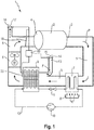
- Fig.1 shows a laundry dryer 1 in the form of a circulating air dryer.
- the laundry drying apparatus 1 has a laundry drying room in the form of a horizontal rotatable laundry drum 2 with a front-side process air outlet opening 3 and a rear process air inlet opening 4.
- the process air outlet opening 3 and the process air inlet opening 4 are connected to one another by means of a process air channel 5 for circulating process air P.
- a process air channel 5 for circulating process air P In the process air duct 5 - in this order in the flow direction of the process air P - a first heat exchanger, a second heat exchanger and a motor-driven process air blower 6 housed.
- the laundry drum 2 and the process air channel 5 represent at least during a normal drying operation or nominal operation a circulating closed process air circuit 2.5.
- the first heat exchanger is designed as an evaporator (or "evaporator") 7 of a heat pump and serves as a condenser with respect to the hot-moist process air P emerging from the process air outlet opening 3.
- the process air P precipitates on the cool heat exchanger surfaces of the evaporator 7, so that it condenses out to form condensate K.
- the condensate K can be collected in a condensate tray 8.
- the second heat exchanger is designed here as a condenser (or “condenser”) 9 of the heat pump and serves as compared to the cool-dry process air P coming from the evaporator 7 as a heater.
- the condenser 9 thus heats the cool-dry process air P.
- the process air blower 6 is arranged downstream of the condenser 9 and upstream of the process air inlet opening 4.
- Warm-dry process air P flowing into the process air inlet opening 4 can absorb moisture from the laundry and then emerge again from the process air outlet opening 3 as warm-moist process air, etc.
- the heat pump is designed here as a compressor heat pump 7, 9, 10, 11, 12 and has in a basically known manner except the evaporator 7 and the condenser 9 a compressor 10 arranged therebetween as a drive and a throttle valve 11.
- These functional elements 7, 9, 10, 11 are interconnected by coolant lines 12 and form a coolant circuit for circulating coolant therein.
- a Kanalabzweig 13 is provided on the process air channel 5, which has a first air passage opening in the form of a supply air opening 14.
- the supply air opening 14 is selectively openable and closable by means of a controllable closure device 15.
- the closure means 15 may be used to close the inlet air opening 14, e.g. a flap, a slider, a valve, etc. have.
- a second air passage opening in the form of an exhaust opening 16 is provided on the process air duct 5.
- the exhaust opening 16 is selectively openable and closable by means of another controllable closure device 17.
- the further closure device 17 may for closing the exhaust port 16 z. As a flap, a slider, a valve, etc. have.
- a shut-off device 18 is further provided in the process air channel 5, by means of which a cross-section of the process air channel 5 can be at least partially opened and closed or released and shut off.
- the shut-off device 18 may be used e.g. a flap, a slider, a valve, etc. have.
- the condenser 9 and the process air blower 6 serving as heating are thus arranged in the process air duct 5 between the supply air opening 14 and the shut-off device 18 and between the supply air opening 14 and the exhaust air opening 16.
- the closure device 15, the further closure device 17 and the shut-off device 18 are connected to a control device 19 for their control or activation.
- the control device 19 can actuate the closure device 15, the further closure device 17 and / or the shut-off device 18 individually or in a predefined relationship to one another.
- the control device 19 can be connected to at least one temperature sensor for temperature-dependent control or actuation of these devices 15, 17 and 18, for example with a temperature sensor 20 arranged in the region of the condenser 9 and / or with a temperature sensor sensing a temperature of the compressor 10 (see FIG .).
- the controller 19 may alternatively or additionally make the control or activation of the devices 15, 17 and 18 dependent on a temporal progress of the drying process.
- the control device 19 in a first setting state, the devices 15, 17th and 18 control so that the supply air opening 14 and the exhaust port 16 are closed and the process air channel 5 is released by the shut-off device 18.
- the process air P can thus circulate unhindered in the process air duct 5. There is virtually no secondary air flow from the supply air opening 14 to the exhaust port 16.
- control device 19 can control the devices 15, 17 and 18 such that the closure device 15 simultaneously controls the inlet air opening 14 at least partially releases, the closure device 17, the exhaust port 16 at least partially releases and the shut-off device 18, the process air channel 5 at least partially blocked. Consequently, by the Zu Kunststoffö réelle 14 comparatively cool ambient air F z. B. sucked from the interior of the laundry dryer 1 in the process air duct 5. Due to the current process air blower 6, the ambient air F or a mixture of the ambient air F and the process air P passes over the condenser 9, which is thereby cooled. The condenser 9 flowing through the cooling liquid of the compressor heat pump 7, 9 to 12 is thereby also cooled more, so that overheating can be avoided.
- shut-off device 18 at least partially obstructs the process air channel 5 ensures that only little or even virtually no ambient air F gets into the laundry drum 2, which saves energy. Also, this prevents the amount of ambient air F reaching the evaporator 7 from being kept low or even completely suppressed, which keeps the efficiency of the compressor heat pump 7, 9, 10, 11, 12 high.
- shut-off or release Under a virtually complete shut-off or release can be understood in particular a shut off or release that for practical purposes of drying clothes is complete. For example, minor leaks may occur that do not significantly reduce efficiency.
- This switching over of the devices 15, 17 and 18 can also be understood as meaning, in particular for cooling the compressor heat pump 7, 9, 10, 11, 12 from a recirculation mode for the process air P to an exhaust air mode for the ambient air F (and possibly a proportion of the process air P) can be switched, and vice versa.
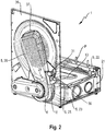
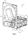
- Fig.2 and Figure 3 show in a view obliquely from behind a possible embodiment of the laundry drying apparatus 1 based on selected components in a partially transparent view.
- the laundry drying apparatus 1 has a bottom group 21, which carries a part of the process air duct 5, namely an air-technically connected to the front side process air outlet opening 3 of the laundry drum 2 (Fig.) Section 22, in a widened portion or a channel widening 23 of Process air duct 5 leads.
- the channel widening 23 of the evaporator 7 and the condenser 9 are housed, such as in Figure 5 and Figure 6 shown.
- the evaporator 7 is disposed closer to the portion 22, so that in the first setting state (corresponding to, eg, a nominal operation), the process air P flowing in through the portion 22 at the front into the channel widening 23 first passes through the evaporator 7 and then through the evaporator 7 Condenser 9 flows.
- the evaporator 7 is separated from the condenser 9 by an air gap 24. After passing through the condenser 9, the process air P is sucked through a short connecting portion 25 of the process air duct 5 to the process air blower 6.
- the process air blower 6 is designed as a radial fan.
- the process air blower 6 blows out the process air P through a further connecting section 26 of the process air duct 5 up to the rear process air inlet opening 4.
- the further connection portion 26 is in Fig.2 translucent and in Figure 3 drawn with a window available only for display.
- the connecting portion 26 is disposed on a rear end shield 36 which covers the process air inlet port through a perforated plate 37.
- the connecting section 26 has the exhaust air opening 16 on one side. Fluidically behind the process air blower 6, the cover 26 also has a laterally inwardly directed projection which serves as an air baffle and as a seat 28, as explained in more detail below.
- the condenser 9 and the process air blower 6 are thus arranged in the process air duct 5 fluidically between the supply air opening 14 and the exhaust opening 16.
- the channel branch 13 is formed as a separately manufactured component and with an open end from the outside to an in Figure 5 and Figure 6 shown opening 29 of the channel widening 23 attached. Namely, the channel branch 13 opens there into the air gap 24.
- the existing at the other end of the Kanalabzweigs 13 supply air opening 14 terminates near the exhaust port 16.
- the supply air opening 14 is directly connected with the air gap air-24.
- the supply air opening 14 and the exhaust opening 16 are arranged practically perpendicular to each other.
- the closure device 15, the further closure device 17 and the shut-off device 18 are parts of a common air guiding device 30, 31 or are integrated in a common air guiding device.
- the louver 30, 31 only a pivotable, one-piece closure member 30 and an actuator 31 for pivoting the closure member 30.
- the closure element 30 may be, for example, a one-piece plastic or metal part.
- the actuator 31 may be, for example, a piezoelectric actuator or an electric motor and can be actuated by the control device 19.
- the closure element 30 has a horizontally oriented axis of rotation 32 in the further connection portion 26 of the process air channel 5 close to an upper edge of the exhaust port 16. From the axis of rotation 32 from here a plate-shaped second portion 33 extends down so that it increases in the Figure 4 shown first actuating state, the exhaust port 16 covers from the inside in the manner of a flap and thus completely closes. By contrast, the process air channel 5 is practically not shut off in the first setting state.
- the first setting state corresponds to a first end position of the closure element 30.
- a first partial region 34 runs vertically from the second partial region 33.
- the first portion 34 is plate-shaped and flat has a circular plane in the plate-like curved course.
- an air guide region 35 which extends perpendicularly to the rear, adjoins here with the same width as the first portion 34.
- the first portion 34 covers the supply air opening 14 and closes it completely. This ensures that in the drying operation without overheating (ie, the nominal operation) practically no ambient air is sucked in targeted, which would reduce the efficiency of the laundry dryer 1.
- the second portion 33 In the second setting state, which corresponds to a second end position, the second portion 33 now presses on the seat 28 and thus blocks the process air channel 5 between the process air blower 6 and the washing drum 2 practically completely. At the same time, the second portion 33 releases the exhaust port 16.
- the second subregion 33 thus serves both as part of the shut-off device 17 in the form of a shut-off flap for shutting off or releasing the process air channel 5 and as part of the further closure device 18 for shutting off or releasing the exhaust air opening 16.
- the first portion 34 thus serves as a closure device in the form of a slide for the supply air opening 14.
- the closure element 30 If the closure element 30 is in the second end position, ambient air F is sucked from the interior of the laundry drying device 1 into the supply air opening 14 while the process air blower 6 is running and flows through the channel branch 13 into the air gap 24. From there, the ambient air F is sucked under heat through the condenser 9 to the process air blower 6, whereby the condenser 9 cools. Ambient air F warmed up by the process air blower 6 is blown back into the interior of the laundry drying apparatus 1 through the exhaust air opening 16. In the second end position, therefore, an exhaust air channel for the ambient air F is formed by the closure element 30, in which the condenser 9 and the process air blower 6 are arranged.
- the actuator 31 may be able to pivot the closure element 30 only between the first end position and the second end position, which allows the use of a particularly simple actuator 31.
- the actuator 31 can adjust the closure element 30 to at least one discrete intermediate position or continuously between the two end positions.
- the closure element 30 may be adjustable such that the supply air opening 14 remains hidden up to an angular position of the closure element 30 of about 20 ° to 30 ° from the first end position through the first portion 34, while the process air channel 5 already by the second Subarea 33 is proportionally locked.
- the second subregion 33 can also be used to reduce the volume flow of the process air P-also independently of a cooling of the heat pump. This opens up additional possibilities for setting or regulating the drying process.
- the process air P can be throttled, so that the heat pump 7, 9 to 12 heats up faster and gets into a favorable process window.
- closure element 30 may be pivoted into at least one further setting state corresponding to at least one second intermediate position, in which the first portion 34 of the closure element 30 completely releases the supply air opening 14 and the second portion 33 only partially blocks the process air channel 5.
- closure element 30 may be pivoted into at least one further setting state corresponding to at least one third intermediate position, in which the first portion 34 of the closure element 30 partially releases the supply air opening 14 and the second portion 33 partially blocks the process air channel 5.
- a number may include exactly the specified number as well as a usual tolerance range, as long as this is not explicitly excluded.
Landscapes
- Engineering & Computer Science (AREA)
- Textile Engineering (AREA)
- Detail Structures Of Washing Machines And Dryers (AREA)
Description
- Die Erfindung betrifft ein Wäschetrocknungsgerät, aufweisend einen Wäschetrocknungsraum mit einer Prozessluft-Einlassöffnung und einer Prozessluft-Austrittsöffnung, welche Öffnungen mittels eines Prozessluftkanals zu einem Prozessluftkreislauf miteinander verbunden sind, wobei in dem Prozessluftkanal ein Kondensator zur Abkühlung von aus dem Wäschetrocknungsraum austretender Prozessluft, eine Heizung zum Aufwärmen von zuvor abgekühlter Prozessluft und ein Prozessluftgebläse zum Umwälzen der Prozessluft in dem Prozessluftkreislauf angeordnet sind, ferner aufweisend eine Wärmepumpe mit einem Antrieb, einem als der Kondensator dienenden ersten Wärmetauscher und einem als die Heizung dienenden zweiten Wärmetauscher, und zudem aufweisend eine steuerbare Verschlusseinrichtung zum wahlweisen Öffnen und Verschließen einer ersten Luftdurchtrittsöffnung des Prozessluftkreislaufs. Die Erfindung ist insbesondere vorteilhaft anwendbar auf Haushalts-Wäschetrocknungsgeräte.
- Bei Wärmepumpentrocknern mit einer Kompressor-Wärmepumpe heizt sich die Wärmepumpe häufig über einen zeitlichen Verlauf einer Trocknung auf. Damit es nicht zu einer Überhitzung des Kompressors kommt, wird bei einigen Wärmepumpentrocknern mit Erreichen einer Grenztemperatur ein Zusatzventilator eingeschaltet, der Umgebungsluft von außen in den Wärmepumpentrockner ansaugt und auf den Kompressor und eine Verrohrung der Wärmepumpe leitet. Die Umgebungsluft kühlt den Kompressor und führt Wärme aus der Wärmepumpe ab. Der Zusatzventilator befindet sich meist an einer Frontseite des Geräts. Es gibt Ausführungen, bei denen hinter dem Zusatzventilator ein separater Wärmetauscher angeordnet ist, um die Wärmeabfuhr aus dem Kältekreislauf der Wärmepumpe zu erhöhen. Jedoch ist diese Bauform aufwändig. Der Zusatzventilator erzeugt zudem deutlich hörbare Geräusche.
-
DE 40 23 000 C2 offenbart einen Wäschetrockner mit einem zum Heizen von Prozessluft, die mittels eines elektromotorisch angetriebenen Gebläses in einem geschlossenen Prozessluftkanal durch einen Wäschetrockenraum geführt wird, und zum Ausfällen der in der Prozessluft aus dem Wäschetrockenraum mitgeführten Feuchtigkeit eingerichteten Wärmepumpenkreis aus Verflüssiger, Verdampfer, Kompressor und Drossel sowie ferner mit einer einstellbaren Abluftöffnung im Prozessluftkanal zwischen dem Verflüssiger und dem Wäschetrockenraum, wobei zwischen dem Verdampfer und dem Verflüssiger im Prozessluftkanal eine Zuluftöffnung angeordnet ist, die mit einer steuerbaren Verschlusseinrichtung verschließbar ist. -
DE 10 2008 043 176 A1 betrifft einen Trockner mit einer Trocknungskammer für zu trocknende Gegenstände, einem Zuluftkanal, einem Prozessluftkanal, einem Abluftkanal und einer Wärmepumpe mit einer Wärmesenke und einer Wärmequelle, wobei der Zuluftkanal und der Abluftkanal mittels eines Mechanismus über einen Umluftkanal zur Einstellung eines Anteils an Um- und Abluft im Trockner zusammengeschaltet werden können. Auch offenbart sind ein Verfahren zum Betrieb dieses Trockners sowie ein Verfahren zur Steuerung der Temperatur und/oder der Feuchtigkeit einer Luft eines Raumes unter Verwendung dieses Trockners. -
JP 2007-22455 A - Es ist die Aufgabe der vorliegenden Erfindung, die Nachteile des Standes der Technik zumindest teilweise zu überwinden und insbesondere eine Möglichkeit zur verbesserten Kühlung einer Wärmepumpe in einem Wäschetrocknungsgerät, insbesondere in einem Umluft-Wäschetrockner, bereitzustellen.
- Diese Aufgabe wird gemäß den Merkmalen der unabhängigen Ansprüche gelöst. Bevorzugte Ausführungsformen sind insbesondere den abhängigen Ansprüchen entnehmbar. Die Aufgabe wird gelöst durch ein Wäschetrocknungsgerät, aufweisend einen Wäschetrocknungsraum mit einer Prozessluft-Einlassöffnung und einer Prozessluft-Austrittsöffnung, welche Öffnungen mittels eines Prozessluftkanals zu einem Prozessluftkreislauf miteinander verbunden sind, wobei in dem Prozessluftkanal ein Kondensator zur Abkühlung von aus dem Wäschetrocknungsraum austretender Prozessluft, eine Heizung zum Aufwärmen von zuvor abgekühlter Prozessluft und ein Prozessluftgebläse zum Umwälzen der Prozessluft in dem Prozessluftkreislauf angeordnet sind, ferner aufweisend eine Wärmepumpe mit einem Antrieb, einem als der Kondensator dienenden ersten Wärmetauscher und einem als die Heizung dienenden zweiten Wärmetauscher, zudem aufweisend eine steuerbare Verschlusseinrichtung zum wahlweisen Öffnen und Verschließen einer ersten Luftdurchtrittsöffnung des Prozessluftkreislaufs, und aufweisend eine steuerbare Absperreinrichtung zum wahlweisen Öffnen und Verschließen des Prozessluftkanals, wobei die Heizung und das Prozessluftgebläse in dem Prozessluftkanal zwischen der ersten Luftdurchtrittsöffnung und der Absperreinrichtung angeordnet sind und die Verschlusseinrichtung und die Absperreinrichtung so steuerbar sind, dass gleichzeitig die Verschlusseinrichtung die erste Luftdurchtrittsöffnung zumindest teilweise freigibt und die Absperreinrichtung den Prozessluftkanal zumindest teilweise absperrt.
- Dieses Wäschetrocknungsgerät weist unter anderem den Vorteil auf, dass während eines Kühlvorganges mit versperrtem Prozessluftkanal strömt keine Luft durch den Wäschetrocknungsraum und somit keine bzw. nur unwesentlich Feuchtigkeit aus dem Gerät abgeführt wird. Folglich wird der Kondensationswirkungsgrad nicht vermindert. Zudem ist dieses Wäschetrocknungsgerät einfach und preiswert herstellbar. Die durch die erste Luftdurchtrittsöffnung in den Prozessluftkanal einströmende Umgebungsluft mag aus dem Inneren des Wäschetrocknungsgeräts oder von außerhalb des Wäschetrocknungsgeräts angesaugt werden.
- Ein weiterer Vorteil besteht darin, dass auf einen Zusatzventilator und auch auf einen Zusatzwärmetauscher verzichtet werden kann. Insbesondere auch bei Ansaugung der Umgebungsluft aus dem Inneren des Wäschetrocknungsgeräts kann eine Belüftungsöffnung in einer insbesondere frontseitigen Gehäusewand entfallen. Dieser Bereich unterliegt dann weniger Restriktionen und steht z.B. zur designerischen Gestaltung zur Verfügung. Beispielsweise kann das Gerät durch Entfall der frontseitigen Belüftungsöffnung eine glatte Front erhalten. Der Entfall der frontseitigen Belüftungsöffnung ergibt den weiteren Vorteil, dass eine Schallabstrahlung des Kompressors nach vorne erheblich vermindert wird.
- Die Abkühlung der Wärmepumpe erfolgt darüber hinaus wesentlich schneller als durch einen Zusatzventilator. So kann eine Trocknungszeit verkürzt werden. Durch die Abkühlung verschieben sich die Prozesszustände in einen für die Effizienz der Wärmepumpe günstigeren Bereich, so dass ein Gesamtenergieverbrauch verringert werden kann.
- Unter einer Luftdurchtrittsöffnung mag insbesondere eine Öffnung verstanden werden, durch die Luft in den Prozessluftkanal einströmen oder ausströmen kann. Die Luftdurchtrittsöffnung mag in einer Wandung des Prozessluftkanals angeordnet sein, z.B. in Form eines Lochs.
- Das Verschließen oder Absperren des Prozessluftkanals durch die Absperreinrichtung betrifft hingegen eine Änderung eines Strömungsquerschnitts des Prozessluftkanals.
- Das Wäschetrocknungsgerät ist ein Umluft-Wäschetrockner, in dessen Nennbetrieb, bei dem Prozessluft durch den Wäschetrocknungsraum strömt, der Wäschetrocknungsraum und der Prozessluftkanal einen geschlossen umlaufenden Prozessluftkreislauf bilden. Im Kühlbetrieb, bei dem die erste Luftdurchtrittsöffnung zumindest teilweise geöffnet ist und der Prozessluftkanal zumindest teilweise abgesperrt ist, ist ausschließlich oder zusätzlich ein offener Abluftkanal vorhanden, der die Umgebungsluft über die Heizung bzw. den zweiten Wärmetauscher leitet.
- Das Wäschetrocknungsgerät ist insbesondere ein Haushalts-Wäschetrocknungsgerät. Das Wäschetrocknungsgerät mag ein eigenständiger Wäschetrockner oder ein Wasch/Trocknungs-Kombigerät oder Waschtrockner sein.
- Der Wäschetrocknungsraum mag eine Wäschetrommel sein, insbesondere eine drehbare Wäschetrommel. Die Wäschetrommel mag um eine horizontale Drehachse drehbar sein. Die Prozessluft-Einlassöffnung und die Prozessluft-Austrittsöffnung mögen dann an Stirnflächen der Wäschetrommel angeordnet sein. Beispielsweise mag sich die Prozessluft-Einlassöffnung an einer rückwärtigen Stirnfläche der Wäschetrommel befinden und sich die Prozessluft-Austrittsöffnung an einer frontseitigen Stirnfläche der Wäschetrommel befinden.
- An dem als Kondensator dienenden ersten Wärmetauscher kühlt aus der Wäschetrommel ausströmende warm-feuchte Prozessluft ab und wird kondensiert. Das so gewonnene Kondensat tropft z.B. in eine Kondensatwanne und mag in einen Abfluss oder in einen Spülbehälter abgepumpt werden.
- Der als Heizung dienende zweite Wärmetauscher ist in Bezug auf die Strömungsrichtung der Prozessluft stromabwärts oder hinter dem Kondensator bzw. hinter dem ersten Wärmetauscher angeordnet und heizt die auskondensierte Prozessluft wieder auf, bevor sie wieder in die Wäschetrommel einströmt.
- Das Prozessluftgebläse mag insbesondere zwischen der Heizung und der Wäschetrommel angeordnet sein und damit auch in Bezug auf die Strömungsrichtung der Prozessluft stromabwärts zu der Heizung. Das Prozessluftgebläse mag z.B. ein Axiallüfter oder ein Radiallüfter sein.
- Die Wärmepumpe mag eine Kompressor-Wärmepumpe mit einem Kompressor als dem Antrieb, einem Verdampfer als dem ersten Wärmetauscher und einem Verflüssiger als dem zweiten Wärmetauscher sein. Sie weist auf grundsätzlich bekannte Weise auch eine Drossel auf. Diese Komponenten sind auf grundsätzlich bekannte Weise Komponenten eines Kreislaufs, in dem Arbeits- oder Kältemittel zirkuliert. Die Wärmepumpe mag folglich auch als "Kältekreislauf' bezeichnet werden.
- Alternativ mag die Wärmepumpe als eine Stirling-Wärmepumpe oder als eine Vuilleumier-Wärmepumpe ausgebildet sein.
- Die steuerbare Verschlusseinrichtung und die steuerbare Absperreinrichtung sind insbesondere elektrisch steuerbar. Die mögen mittels eines gemeinsamen Aktors (z.B. eines Piezoaktors oder eines Elektromotors) steuerbar sein oder dazu mit einem jeweiligen Aktor gekoppelt sein.
- Dadurch, dass die Heizung und das Prozessluftgebläse in dem Prozessluftkanal zwischen der ersten Luftdurchtrittsöffnung und der Absperreinrichtung angeordnet sind, fließt bei verschlossenem oder abgesperrtem Prozessluftkanal durch diese beiden Komponenten ein signifikanter Volumenstrom der Umgebungsluft. Erfindungsgemäß sind nur die Heizung und das Prozessluftgebläse in dem Prozessluftkanal zwischen der ersten Luftdurchtrittsöffnung und der Absperreinrichtung angeordnet. Somit fließt bei gleichzeitig geöffneter erster Luftdurchtrittsöffnung und bei verschlossenem Prozessluftkanal nur durch diese beiden Komponenten des Prozessluftkanals ein signifikanter Volumenstrom der Umgebungsluft, jedoch z.B. nicht durch den Wäschetrocknungsraum und auch nicht durch den ersten Wärmetauscher bzw. Kondensator. Dadurch lässt sich ein besonders hoher Wirkungsgrad aufrechterhalten.
- Die Prozessluft hat im Nennbetrieb bei Eintritt in den zweiten Wärmetauscher bzw. die Heizung je nach Wärmepumpen/Kältekreislauf- und Gerätekonfiguration eine typische Prozessluft-Temperatur von typischerweise zwischen 35°C und 60°C (ist aber nicht darauf beschränkt). Bei höheren Umgebungstemperaturen und in einer Endphase der Trocknung, bei welcher eine Feuchtigkeit der aus der Prozessluft-Austrittsöffnung des Wäschetrocknungsgeräts ausströmenden Prozessluft sinkt, steigt die Prozessluft-Temperatur. Angesaugte Umgebungsluft liegt mit etwa 15°C bis 30°C deutlich unterhalb der Prozessluft-Temperatur. Der Temperaturgradient zwischen einem in der Wärmepumpe zirkulierenden Kältemittel und der Umgebungsluft ist also signifikant größer als zwischen dem Kältemittel der Wärmepumpe und der Prozessluft. Dies wirkt sich günstig auf die Wärmeübertragung aus.
- Steigen die Temperaturen der Wärmepumpe, kann von dem Nennbetrieb in den Kühlbetrieb umgeschaltet werden. Dazu wird in einer Variante die erste Luftdurchtrittsöffnung zumindest teilweise geöffnet und der Antrieb wird in Betrieb gehalten. Der Prozessluftkreislauf ist unterbrochen und es strömt kein bzw. nur ein sehr geringer Volumenstrom durch den Verdampfer. Es findet an dieser Stelle also kein weiterer Wärmeeintrag in die Wärmepumpe statt, sondern nur noch durch die Arbeit des Antriebs. Damit insgesamt eine Abkühlung der Wärmepumpe stattfindet, muss also die Wärmeabfuhr durch die Umgebungsluft größer sein als die durch die Arbeit des Antriebs erzeugte Wärme. Je größer diese Differenz ist, desto schneller kann die Abkühlung der Wärmepumpe erfolgen und desto geringer ist der Gesamtenergieverlust in dem Kühlbetrieb.
- Es ist eine Weiterbildung, dass ein Volumenstrom der Umgebungsluft im Kühlbetrieb zwischen ca. 10% bis ca. 50% des Volumenstroms der Prozessluft im Nennbetrieb beträgt.
- Es ist noch eine Weiterbildung, dass die erste Luftdurchtrittsöffnung nur für eine relativ kurze Zeit geöffnet wird, insbesondere zwischen ca. 5 s und ca. 100 s, bis eine ausreichende Abkühlung erreicht worden ist.
- Das Umschalten zwischen dem Nennbetrieb und dem Kühlbetrieb mag über eine Temperaturmessung an geeigneter Stelle an der Wärmepumpe ausgelöst werden. Der Kühlbetrieb mag entweder für eine vorgegebene Zeitdauer ablaufen oder über eine Temperaturmessung wieder beendet werden.
- Es ist eine Weiterbildung, dass in einem ersten Stellzustand die Verschlusseinrichtung die erste Luftdurchtrittsöffnung vollständig verschließt und die Absperreinrichtung den Prozessluftkanal vollständig freigibt und in einem zweiten Stellzustand die Verschlusseinrichtung die erste Luftdurchtrittsöffnung freigibt und die Absperreinrichtung den Prozessluftkanal vollständig absperrt. Dadurch lässt sich eine Beimischung von Umgebungsluft zum Prozessluftstrom im Nennbetrieb und eine Beimischung von Prozessluft im Kühlbetrieb vermeiden. Der erste Stellzustand mag auch als eine erste Endstellung, Nennstellung oder Umluftstellung bezeichnet werden, während der zweite Stellzustand auch als zweite Endstellung, Kühlstellung oder Abluftstellung bezeichnet werden kann.
- Es ist zum Erreichen eines hohen Volumenstroms der Umgebungsluft sowie für eine genaue Einstellung des Volumenstroms vorgesehen, dass die Absperreinrichtung wechselweise den Prozessluftkanal zumindest teilweise freigibt oder absperrt und eine zweite Luftdurchtrittsöffnung des Prozessluftkreislaufs mittels einer weiteren Verschlusseinrichtung zumindest teilweise verschlossen oder freigegeben ist, wobei die Heizung und das Prozessluftgebläse in dem Prozessluftkanal zwischen der ersten Luftdurchtrittsöffnung und der zweiten Luftdurchtrittsöffnung angeordnet sind. Gibt also die Absperreinrichtung den Prozessluftkanal zumindest teilweise frei, ist die zweite Luftdurchtrittsöffnung des Prozessluftkreislaufs zumindest teilweise verschlossen, und umgekehrt. Die Umgebungsluft strömt im Kühlbetrieb also zuerst durch die erste Luftdurchtrittsöffnung in den Prozessluftkanal ein und tritt an der zweiten Luftdurchtrittsöffnung wieder aus, oder umgekehrt. Diejenige Luftdurchtrittsöffnung, durch die Umgebungsluft in den Prozessluftkanal einströmt, mag auch als Zuluftöffnung bezeichnet werden. Diejenige Luftdurchtrittsöffnung, durch die Luft aus dem Prozessluftkanal austritt, mag auch als Abluftöffnung bezeichnet werden. Die Richtung der Luftströmung ist durch das Prozessluftgebläse vorgegeben und mag immer die gleiche Richtung durch das Prozessluftgebläse aufweisen oder einen Richtungswechsel erfahren.
- Die zweite Luftdurchtrittsöffnung mag durch die weitere Verschlusseinrichtung wahlweise öffenbar und verschließbar sein.
- Es ist eine für eine besonders vielgestaltige Luftführung vorteilhafte Ausgestaltung, dass in mindestens einem dritten Stellzustand die Verschlusseinrichtung die erste Luftdurchtrittsöffnung vollständig verschließt und die Absperreinrichtung den Prozessluftkanal teilweise absperrt. Der dritte Stellzustand mag auch als Zwischenstellung bezeichnet werden. Die zweite Luftdurchtrittsöffnung mag insbesondere teilweise geöffnet oder verschlossen sein.
- Alternativ oder zusätzlich mag in mindestens einem weiteren dritten Stellzustand die Verschlusseinrichtung die erste Luftdurchtrittsöffnung vollständig freigeben und die Absperreinrichtung den Prozessluftkanal teilweise absperren. Die zweite Luftdurchtrittsöffnung mag, falls vorhanden, insbesondere teilweise geöffnet sein.
- Auch mag in mindestens einem weiteren dritten Stellzustand die Verschlusseinrichtung die erste Luftdurchtrittsöffnung teilweise freigeben und die Absperreinrichtung den Prozessluftkanal teilweise absperren. Die zweite Luftdurchtrittsöffnung mag insbesondere teilweise geöffnet sein.
- Es ist erfindungsgemäß besonders einfach, preiswert und kompakt umsetzbar, dass die Verschlusseinrichtung und die Absperreinrichtung Teile einer einsamen Luftleiteinrichtung darstellen. Da eine zweite Luftdurchtrittsöffnung mit einer zugehörigen weiteren Verschlusseinrichtung vorhanden sind, stellen zu diesem Zweck die Verschlusseinrichtung für die erste Luftdurchtrittsöffnung, die weitere Verschlusseinrichtung für die zweite Luftdurchtrittsöffnung und die Absperreinrichtung Teile einer einsamen Luftleiteinrichtung dar. Die Teile mögen insbesondere mittels eines gemeinsamen Aktors bewegbar sein, was eine besonders leichte Einstellung eines Stellzustands ermöglicht.
- Es ist erfindungsgemäß ganz besonders einfach, preiswert und kompakt umsetzbar, dass die Luftleiteinrichtung ein bewegbares Verschlusselement aufweisen, das eine als die Verschlusseinrichtung dienenden ersten Teilbereich und einen als die Absperreinrichtung und die weitere Verschlusseinrichtung dienenden zweiten Teilbereich aufweist.
- Das Verschlusselement mag insbesondere ein verschwenkbares Verschlusselement sein, kann aber z.B. auch ein linear verschiebbares Verschlusselement sein. Die Teilbereiche mögen z.B. als Klappe, Ventil und/oder Schieber ausgebildet sein.
- Es ist ferner eine Ausgestaltung, dass der erste Wärmetauscher oder Kondensator und der zweite Wärmetauscher oder Heizung durch einen Spalt getrennt nebeneinander angeordnet sind. Der Spalt ermöglicht ein Einbringen der Umgebungsluft hinter dem Kondensator und vor der Heizung ohne aufwändige bauliche Maßnahmen. Die erste Luftdurchlassöffnung ist dazu vorteilhafterweise lufttechnisch direkt mit dem Spalt verbunden. Unter einer direkten Verbindung mag insbesondere eine nur lufttechnische Verbindung verstanden werden, bei der zwischen der ersten Luftdurchlassöffnung und dem Spalt keine Funktionselemente des Prozessluftkreislaufs oder der Wärmepumpe angeordnet sind. Die lufttechnische Verbindung mag über einen Kanal bereitgestellt sein.
- Es ist eine praktisch besonders einfach und sicher umsetzbare Ausgestaltung, dass der erste Teilbereich des Verschlusselements als ein Schieber ausgebildet ist und der zweite Teilbereich des Verschlusselements als eine Klappe ausgebildet ist, so dass in einem ersten Stellzustand (z.B. entsprechend einer ersten Endstellung) der erste Teilbereich des Verschlusselements über die erste Luftdurchlassöffnung geschoben ist und der zweite Teilbereich auf der zweiten Luftdurchlassöffnung aufliegt und in einem zweiten Stellzustand (z.B. entsprechend einer zweiten Endstellung) der erste Teilbereich des Verschlusselements zumindest teilweise von der ersten Luftdurchlassöffnung weggeschoben ist und der zweite Teilbereich von der zweiten Luftdurchlassöffnung abgehoben ist und auf einem Sitz in dem Prozessluftkanal aufliegt.
- In dem ersten Stellzustand sind also die erste Luftdurchlassöffnung durch den ersten Teilbereich und die zweite Luftdurchlassöffnung durch den zweiten Teilbereich verschlossen, während der Prozessluftkanal freigegeben ist. In dem zweiten Stellzustand ist die erste Luftdurchlassöffnung mittels des ersten Teilbereichs zumindest teilweise (insbesondere ganz) freigegeben, die zweite Luftdurchlassöffnung mittels des zweiten Teilbereichs zumindest teilweise (insbesondere ganz) geöffnet und der Prozessluftkanal zumindest teilweise (insbesondere ganz) versperrt.
- Der erste Teilbereich mag insbesondere ein plattenförmiger Teilbereich sein. Der zweite Teilbereich mag insbesondere ein plattenförmiger Teilbereich sein, der senkrecht von dem ersten Teilbereich absteht. Der erste Teilbereich mag in der ersten Endstellung auf der zweiten Luftdurchlassöffnung aufliegen und in der zweiten Endstellung auf einem in dem Prozessluftkanal befindlichen Sitz aufsitzen.
- Das Verschlusselement mag beispielsweise aus Kunststoff oder aus Metall bestehen. Es mag insbesondere einstückig hergestellt worden sein, z.B. mittels eines Gussverfahrens, beispielsweise eines Spritzgussverfahrens, und folglich ein Gussteil sein.
- Allgemein mag im Kühlbetrieb die Umgebungsluft aus dem Inneren des Wäschetrocknungsgeräts oder von außerhalb des Wäschetrocknungsgeräts angesaugt werden. Auch mag im Kühlbetrieb allgemein die aus dem Prozessluftkanal wieder ausströmende Luft in das Innere des Wäschetrocknungsgeräts oder aus dem Wäschetrocknungsgerät heraus abgegeben werden.
- Die Aufgabe wird auch gelöst durch ein Verfahren zum Betreiben eines Wäschetrocknungsgeräts, welches einen Wäschetrocknungsraum aufweist, dessen Öffnungen mittels eines Prozessluftkanals zu einem Prozessluftkreislauf miteinander verbunden sind, wobei in dem Prozessluftkanal eine Heizung zum Aufwärmen von zuvor abgekühlter Prozessluft und ein Prozessluftgebläse zum Umwälzen der Prozessluft in dem Prozessluftkreislauf angeordnet sind, und welches Wäschetrocknungsgerät eine Wärmepumpe mit einem als die Heizung dienenden Wärmetauscher aufweist, wobei bei dem Verfahren zwischen einem Umluftbetrieb für die Prozessluft in dem Prozessluftkreislauf (z.B. während eines Nennbetriebs des Wäschetrocknungsgeräts) und einem Abluftbetrieb (z.B. während eines Kühlbetriebs des Wäschetrocknungsgeräts) für Umgebungsluft umgeschaltet wird, wobei während des Abluftbetriebs mittels des Prozessluftgebläses Umgebungsluft über die Heizung geleitet wird und der Prozessluftkanal zwischen der Heizung und dem Wäschetrocknungsraum zumindest teilweise blockiert oder querschnittsreduziert wird. Dieses Verfahren kann analog zu dem Wäschetrocknungsgerät ausgebildet werden und weist die gleichen Vorteile auf.
- Beispielsweise mag während des Abluftbetriebs ein Antrieb der Wärmepumpe (z.B. ein Kompressor) betrieben werden bzw. der Antrieb in Betrieb sein.
- Die oben beschriebenen Eigenschaften, Merkmale und Vorteile dieser Erfindung sowie die Art und Weise, wie diese erreicht werden, werden klarer und deutlicher verständlich im Zusammenhang mit der folgenden schematischen Beschreibung eines Ausführungsbeispiels, das im Zusammenhang mit den Zeichnungen näher erläutert wird.
- Fig.1
- zeigt ein Funktionsschaltbild eines erfindungsgemäßen Wäschetrocknungsgeräts;
- Fig.2
- zeigt in einer teilweise transparenten Ansicht von schräg hinten Komponenten eines erfindungsgemäßen Wäschetrocknungsgeräts gemäß einer Weiterbildung der
Fig.1 mit einer Luftleiteinrichtung in einer ersten Endstellung; - Fig.3
- zeigt das erfindungsgemäße Wäschetrocknungsgerät als Strichzeichnung in einer zu
Fig.2 analogen Darstellung; - Fig.4
- zeig einen Ausschnitt aus
Fig.3 im Bereich der Luftleiteinrichtung; - Fig.5
- zeigt als Schnittdarstellung in Schrägansicht Komponenten des erfindungsgemäßen Wäschetrocknungsgeräts mit der Luftleiteinrichtung in einer zweiten Endstellung; und
- Fig.6
- zeigt als Schnittdarstellung in Seitenansicht Komponenten des erfindungsgemäßen Wäschetrocknungsgeräts mit der Luftleiteinrichtung in der zweiten Endstellung.
-
Fig.1 zeigt ein Wäschetrocknungsgerät 1 in Form eines Umluft-Wäschetrockners. Das Wäschetrocknungsgerät 1 weist einen Wäschetrocknungsraum in Form einer horizontal drehbaren Wäschetrommel 2 mit einer frontseitigen Prozessluft-Austrittsöffnung 3 und einer rückseitigen Prozessluft-Einlassöffnung 4 auf. Die Prozessluft-Austrittsöffnung 3 und die Prozessluft-Einlassöffnung 4 sind mittels eines Prozessluftkanals 5 zum Umwälzen von Prozessluft P miteinander verbunden sind. In dem Prozessluftkanal 5 sind - in dieser Reihenfolge in Strömungsrichtung der Prozessluft P - ein erster Wärmetauscher, ein zweiter Wärmetauscher und ein elektromotorisch angetriebenes Prozessluftgebläse 6 untergebracht. Die Wäschetrommel 2 und der Prozessluftkanal 5 stellen zumindest während eines normalen Trocknungsbetriebs oder Nennbetriebs einen umlaufend geschlossenen Prozessluftkreis 2,5 dar. - Der erste Wärmetauscher ist als ein Verdampfer (oder "Evaporator") 7 einer Wärmepumpe ausgebildet und dient gegenüber der aus der Prozessluft-Austrittsöffnung 3 austretenden warm-feuchten Prozessluft P als ein Kondensator. Die Prozessluft P schlägt sich an den kühlen Wärmetauscherflächen des Verdampfers 7 nieder, so dass sie unter Bildung von Kondensat K auskondensiert. Das Kondensat K kann in einer Kondensatwanne 8 aufgefangen werden.
- Der zweite Wärmetauscher ist hier als ein Verflüssiger (oder "Kondensor") 9 der Wärmepumpe ausgebildet und dient gegenüber von dem Verdampfer 7 kommenden kühltrockenen Prozessluft P als eine Heizung. Der Verflüssiger 9 erwärmt also die kühltrockene Prozessluft P.
- Das Prozessluftgebläse 6 ist stromabwärts des Verflüssigers 9 und vor der Prozessluft-Einlassöffnung 4 angeordnet. In die Prozessluft-Einlassöffnung 4 einströmende warmtrockene Prozessluft P kann Feuchtigkeit aus der Wäsche aufnehmen und dann als warm-feuchte Prozessluft wieder aus der Prozessluft-Austrittsöffnung 3 austreten usw.
- Die Wärmepumpe ist hier als eine Kompressor-Wärmepumpe 7, 9, 10, 11, 12 ausgestaltet und weist in grundsätzlich bekannter Weise außer dem Verdampfer 7 und dem Verflüssiger 9 einen dazwischen angeordneten Kompressor 10 als Antrieb und ein Drosselventil 11 auf. Diese Funktionselemente 7, 9, 10, 11 sind durch Kühlmittelleitungen 12 miteinander verbunden und bilden einen Kühlmittelkreis für darin zirkulierendes Kühlmittel.
- Zwischen dem Verdampfer 7 und dem Verflüssiger 9 ist an dem Prozessluftkanal 5 ein Kanalabzweig 13 vorgesehen, der eine erste Luftdurchtrittsöffnung in Form einer Zuluftöffnung 14 aufweist. Die Zuluftöffnung 14 ist mittels einer steuerbaren Verschlusseinrichtung 15 wahlweise öffenbar und verschließbar. Die Verschlusseinrichtung 15 mag zum Verschließen der Zuluftöffnung 14 z.B. eine Klappe, einen Schieber, ein Ventil usw. aufweisen.
- Zwischen dem Verflüssiger 9 und der Wäschetrommel 2 ist an dem Prozessluftkanal 5 eine zweite Luftdurchtrittsöffnung in Form einer Abluftöffnung 16 vorgesehen. Die Abluftöffnung 16 ist mittels einer weiteren steuerbaren Verschlusseinrichtung 17 wahlweise öffenbar und verschließbar. Die weitere Verschlusseinrichtung 17 mag zum Verschließen der Abluftöffnung 16 z. B. eine Klappe, einen Schieber, ein Ventil usw. aufweisen.
- Zwischen dem Verflüssiger 9 und der Wäschetrommel 2 ist in dem Prozessluftkanal 5 ferner eine Absperreinrichtung 18 vorgesehen, mittels welcher ein Querschnitt des Prozessluftkanals 5 zumindest teilweise geöffnet und verschlossen bzw. freigegeben und abgesperrt werden kann. Die Absperreinrichtung 18 mag dazu z.B. eine Klappe, einen Schieber, ein Ventil usw. aufweisen. Der als Heizung dienende Verflüssiger 9 und das Prozessluftgebläse 6 sind also in dem Prozessluftkanal 5 zwischen der Zuluftöffnung 14 und der Absperreinrichtung 18 und zwischen der Zuluftöffnung 14 und der Abluftöffnung 16 angeordnet.
- Die Verschlusseinrichtung 15, die weitere Verschlusseinrichtung 17 und die Absperreinrichtung 18 sind zu ihrer Steuerung oder Aktivierung an eine Steuereinrichtung 19 angeschlossen. Die Steuereinrichtung 19 kann die Verschlusseinrichtung 15, die weitere Verschlusseinrichtung 17 und/oder die Absperreinrichtung 18 individuell oder in einer vorgegebenen Beziehung zueinander betätigen. Die Steuereinrichtung 19 kann zur temperaturabhängigen Steuerung oder Betätigung dieser Einrichtungen 15, 17 und 18 mit mindestens einem Temperatursensor verbunden sein, beispielsweise mit einem im Bereich des Verflüssigers 9 angeordneten Temperatursensor 20 und/oder mit einem eine Temperatur des Kompressors 10 abfühlenden Temperatursensors (o. Abb.). Die Steuereinrichtung 19 kann die Steuerung oder Aktivierung der Einrichtungen 15, 17 und 18 alternativ oder zusätzlich von einem zeitlichen Fortschritt des Trockenprozesses abhängig machen.
- Insbesondere bei einem Zustand des Wäschetrocknungsgeräts 1, bei dem keine Überhitzung des Kühlmittelkreislaufs bzw. Kompressor-Wärmepumpe 7, 9, 10, 11, 12 vorliegt oder droht (z.B. im Nennbetrieb), kann die Steuereinrichtung 19 in einem ersten Stellzustand die Einrichtungen 15, 17 und 18 so steuern, dass die Zuluftöffnung 14 und die Abluftöffnung 16 verschlossen sind und der Prozessluftkanal 5 durch die Absperreinrichtung 18 freigegeben ist. Die Prozessluft P kann also ungehindert in dem Prozessluftkanal 5 zirkulieren. Es tritt praktisch kein Nebenluftstrom von der Zuluftöffnung 14 zu der Abluftöffnung 16 auf.
- Um eine Überhitzung des Kühlmittelkreislaufs bzw. Kompressor-Wärmepumpe 7, 9, 10, 11, 12, insbesondere des Kompressors 10, zu vermeiden, kann die Steuereinrichtung 19 die Einrichtungen 15, 17 und 18 so steuern, dass gleichzeitig die Verschlusseinrichtung 15 die Zuluftöffnung 14 zumindest teilweise freigibt, die Verschlusseinrichtung 17 die Abluftöffnung 16 zumindest teilweise freigibt und die Absperreinrichtung 18 den Prozessluftkanal 5 zumindest teilweise versperrt. Folglich wird durch die Zuluftöffnung 14 vergleichsweise kühle Umgebungsluft F z. B. aus dem Innenraum des Wäschetrocknungsgeräts 1 in den Prozessluftkanal 5 eingesaugt. Durch das laufende Prozessluftgebläse 6 überstreicht die Umgebungsluft F oder eine Mischung aus der Umgebungsluft F und der Prozessluft P den Verflüssiger 9, der dadurch abgekühlt wird. Die den Verflüssiger 9 durchströmende Kühlflüssigkeit der Kompressor-Wärmepumpe 7, 9 bis 12 wird dadurch ebenfalls stärker abgekühlt, so dass eine Überhitzung vermieden werden kann.
- Dadurch, dass die Absperreinrichtung 18 den Prozessluftkanal 5 zumindest teilweise versperrt, wird erreicht, dass eine nur geringe oder sogar praktisch keine Umgebungsluft F in die Wäschetrommel 2 gelangt, was Energie einspart. Auch wird dadurch verhindert, dass die Menge der zu dem Verdampfer 7 gelangenden Umgebungsluft F gering gehalten wird oder sogar ganz unterbunden wird, was eine Effizienz der Kompressor-Wärmepumpe 7, 9, 10, 11, 12 hoch hält. Diese Vorteile werden insbesondere dadurch erreicht, dass die Absperreinrichtung 18 den Prozessluftkanal 5 praktisch vollständig absperren kann und die Zuluftöffnung 14 und die Abluftöffnung 16 praktisch vollständig freigeben kann.
- Unter einem praktisch vollständigen Absperren oder Freigeben kann insbesondere ein Absperren oder Freigeben verstanden werden, dass für praktische Zwecke der Wäschetrocknung vollständig ist. Beispielsweise mögen geringfügige Leckagen auftreten, die einen Wirkungsgrad aber nicht merklich mindern.
- Dieses Umschalten der Einrichtungen 15, 17 und 18 kann auch so verstanden werden, dass insbesondere zum Abkühlen der Kompressor-Wärmepumpe 7, 9, 10, 11, 12 von einem Umluftbetrieb für die Prozessluft P zu einem Abluftbetrieb für die Umgebungsluft F (und ggf. einen Anteil der Prozessluft P) umgeschaltet werden kann, und umgekehrt.
-
Fig.2 undFig.3 zeigen in einer Ansicht von schräg hinten eine mögliche Ausgestaltung des Wäschetrocknungsgeräts 1 anhand ausgesuchter Komponenten in einer teilweise transparenten Ansicht. Das Wäschetrocknungsgerät 1 weist eine Bodengruppe 21 auf, die einen Teil des Prozessluftkanals 5 trägt, nämlich einen mit der frontseitigen Prozessluft-Austrittsöffnung 3 der Wäschetrommel 2 (o. Abb.) lufttechnisch verbundenen Abschnitt 22, der in einen verbreiterten Abschnitt oder eine Kanalverbreiterung 23 des Prozessluftkanals 5 führt. In der Kanalverbreiterung 23 sind der Verdampfer 7 und der Verflüssiger 9 untergebracht, wie z.B. auch inFig.5 undFig.6 gezeigt. - Und zwar ist der Verdampfer 7 näher an dem Abschnitt 22 angeordnet, so dass im ersten Stellzustand (entsprechend z. B. einem Nennbetrieb) die durch den Abschnitt 22 frontseitig in die Kanalverbreiterung 23 einströmende Prozessluft P folgend zuerst durch den Verdampfer 7 und dann durch den Verflüssiger 9 strömt. Der Verdampfer 7 ist durch einen Luftspalt 24 von dem Verflüssiger 9 getrennt. Nach Durchlaufen des Verflüssigers 9 wird die Prozessluft P durch einen kurzen Verbindungsabschnitt 25 des Prozessluftkanals 5 zu dem Prozessluftgebläse 6 gesaugt. Das Prozessluftgebläse 6 ist als ein Radiallüfter ausgebildet. Das Prozessluftgebläse 6 bläst die Prozessluft P durch einen weiteren Verbindungsabschnitt 26 des Prozessluftkanals 5 bis zu der rückseitigen Prozessluft-Einlassöffnung 4 aus. Der weitere Verbindungsabschnitt 26 ist in
Fig.2 durchscheinend und inFig.3 mit einem nur zur Darstellung vorhandenen Fenster eingezeichnet. Der Verbindungsabschnitt 26 ist an einem hinteren Lagerschild 36 angeordnet, das die Prozessluft-Einlassöffnung durch ein gelochtes Blech 37 abdeckt. - Der Verbindungsabschnitt 26 weist an einer Seite die Abluftöffnung 16 auf. Strömungstechnisch hinter dem Prozessluftgebläse 6 weist die Abdeckung 26 ferner einen seitlich nach innen gerichteten Vorsprung auf, der als ein Luftleitblech und als ein Sitz 28 dient, wie weiter unten genauer erklärt wird. Der Verflüssiger 9 und das Prozessluftgebläse 6 sind in dem Prozessluftkanal 5 also strömungstechnisch zwischen der Zuluftöffnung 14 und der Abluftöffnung 16 angeordnet.
- Der Kanalabzweig 13 ist als ein separat hergestelltes Bauteil ausgebildet und mit einem offenen Ende von außen auf eine in
Fig.5 undFig.6 gezeigte Öffnung 29 der Kanalverbreiterung 23 aufgesetzt. Und zwar mündet der Kanalabzweig 13 dort in den Luftspalt 24. Die am anderen Ende des Kanalabzweigs 13 vorhandene Zuluftöffnung 14 endet nahe der Abluftöffnung 16. Die Zuluftöffnung 14 ist lufttechnisch direkt mit dem Luftspalt 24 verbunden. Die Zuluftöffnung 14 und die Abluftöffnung 16 sind praktisch senkrecht zueinander angeordnet. - Wie nun insbesondere unter Bezug auf
Fig.3 undFig.4 genauer beschrieben wird, stellen die Verschlusseinrichtung 15, die weitere Verschlusseinrichtung 17 und die Absperreinrichtung 18 Teile einer gemeinsamen Luftleiteinrichtung 30, 31 dar bzw. sind in eine gemeinsame Luftleiteinrichtung integriert. Dies ermöglicht ein besonders einfaches, preiswertes und kompaktes Umschalten zwischen mindestens zwei Stellzuständen der Einrichtungen 15, 17 und 18. Und zwar weist die Luftleiteinrichtung 30, 31 lediglich ein verschwenkbares, einstückiges Verschlusselement 30 sowie einen Aktor 31 zum Verschwenken des Verschlusselements 30 auf. Das Verschlusselement 30 mag beispielsweise ein einstückiges Kunststoff- oder Metallteil sein. Der Aktor 31 mag z.B. ein Piezoaktor oder ein Elektromotor sein und ist durch die Steuereinrichtung 19 betätigbar. - Das Verschlusselement 30 weist eine horizontal ausgerichtete Drehachse 32 in dem weiteren Verbindungsabschnitt 26 des Prozessluftkanals 5 nahe an einem oberen Rand der Abluftöffnung 16 auf. Von der Drehachse 32 aus erstreckt sich ein hier plattenförmiger zweiter Teilbereich 33 so nach unten, dass er in dem vergrößert in
Fig.4 gezeigten ersten Stellzustand die Abluftöffnung 16 von innen nach Art einer Klappe abdeckt und damit vollständig verschließt. Der Prozessluftkanal 5 wird in dem ersten Stellzustand hingegen praktisch nicht abgesperrt. Der erste Stellzustand entspricht einer ersten Endstellung des Verschlusselements 30. - In Bezug auf den Prozessluftkanal 5 außenseitig geht von dem zweiten Teilbereich 33 senkrecht ein erster Teilbereich 34 ab. Der erste Teilbereich 34 ist plattenförmig eben und weist einen in Plattenebene kreissektorartig gekrümmten Verlauf auf. An seinem dem ersten Teilbereich 33 abgewandten Rand schließt sich ein senkrecht nach hinten abgehender Luftleitbereich 35 mit hier gleicher Breite wie der erste Teilbereich 34 an. In der ersten Endstellung überdeckt der erste Teilbereich 34 die Zuluftöffnung 14 und verschließt sie damit vollständig. Dadurch wird erreicht, dass im Trocknungsbetrieb ohne Überhitzung (d.h., dem Nennbetrieb) praktisch keine Umgebungsluft gezielt eingesaugt wird, was einen Wirkungsgrad des Wäschetrocknungsgeräts 1 verringern würde.
- Beispielsweise zum Kühlen der Kompressor-Wärmepumpe 7, 9 bis 12 kann durch Aktivierung des Aktors 31 das Verschlusselement 30 von dem ersten Stellzustand bzw. der ersten Endstellung in einen zweiten Stellzustand verschwenkt werden, was in
Fig.5 undFig.6 genauer gezeigt ist. - In dem zweiten Stellzustand, welcher einer zweiten Endstellung entspricht, drückt der zweite Teilbereich 33 nun auf den Sitz 28 und versperrt damit den Prozessluftkanal 5 zwischen dem Prozessluftgebläse 6 und der Wäschetrommel 2 praktisch vollständig. Gleichzeitig gibt der zweite Teilbereich 33 die Abluftöffnung 16 frei. Der zweite Teilbereich 33 dient also sowohl als Teil der Absperreinrichtung 17 in Form einer Absperrklappe zum Absperren bzw. Freigeben des Prozessluftkanals 5 und als Teil der weiteren Verschlusseinrichtung 18 zum Absperren bzw. Freigeben der Abluftöffnung 16.
- Auch ist nun der erste Teilbereich 34 von der Zuluftöffnung 14 wegverschoben worden, die damit ebenfalls freiliegt bzw. offen ist. Der erste Teilbereich 34 dient somit als eine Verschlusseinrichtung in Form eines Schiebers für die Zuluftöffnung 14.
- Zudem ist nun ein unterer Teil der Abluftöffnung 16 durch den Luftleitbereich 35 abgedeckt. Dadurch wird verhindert, dass ein aus der Abluftöffnung 16 austretender warmer Luftstrom zumindest teilweise durch die Zuluftöffnung 14 wieder angesaugt wird. Ein Volumenstrom eines durch die Abluftöffnung 16 hindurchtretenden Luftstroms wird dadurch hingegen nicht oder nicht merklich verringert.
- Befindet sich das Verschlusselement 30 in der zweiten Endstellung, wird bei laufendem Prozessluftgebläse 6 Umgebungsluft F aus dem Inneren des Wäschetrocknungsgeräts 1 in die Zuluftöffnung 14 eingesaugt und strömt durch den Kanalabzweig 13 in den Luftspalt 24. Von dort wird die Umgebungsluft F unter Erwärmung durch den Verflüssiger 9 zu dem Prozessluftgebläse 6 gesaugt, wodurch der Verflüssiger 9 abkühlt. Von dem Prozessluftgebläse 6 aufgewärmte Umgebungsluft F wird durch die Abluftöffnung 16 wieder in das Innere des Wäschetrocknungsgeräts 1 eingeblasen. In der zweiten Endstellung wird durch das Verschlusselement 30 also ein Abluftkanal für die Umgebungsluft F gebildet, in dem der Verflüssiger 9 und das Prozessluftgebläse 6 angeordnet sind.
- Der Aktor 31 mag das Verschlusselement 30 nur zwischen der ersten Endstellung und der zweiten Endstellung verschwenken können, was die Verwendung eines besonders einfachen Aktors 31 ermöglicht. Alternativ kann der Aktor 31 das Verschlusselement 30 auf mindestens eine diskrete Zwischenstellung oder kontinuierlich zwischen den beiden Endstellungen einstellen.
- Beispielsweise mag das Verschlusselement 30 derart stellbar sein, dass die Zuluftöffnung 14 bis zu einer Winkelstellung des Verschlusselements 30 von ca. 20° bis 30° aus der ersten Endstellung heraus noch durch den ersten Teilbereich 34 verdeckt bleibt, während der Prozessluftkanal 5 bereits durch den zweiten Teilbereich 33 anteilig verblockt wird. Auf diese Weise kann der zweite Teilbereich 33 - auch unabhängig von einer Kühlung der Wärmepumpe - zur Reduktion des Volumenstroms der Prozessluft P eingesetzt werden. Dadurch eröffnen sich zusätzliche Möglichkeiten zur Einstellung oder Regelung des Trocknungsablaufs. Beispielsweise kann in einer Startphase die Prozessluft P gedrosselt werden, damit sich die Wärmepumpe 7, 9 bis 12 schneller aufheizt und in ein günstiges Prozessfenster gelangt.
- Alternativ oder zusätzlich mag das Verschlusselement 30 in mindestens einen weiteren Stellzustand entsprechend mindestens einer zweiten Zwischenstellung verschwenkt werden, in dem der erste Teilbereich 34 des Verschlusselements 30 die Zuluftöffnung 14 vollständig freigibt und der zweite Teilbereich 33 den Prozessluftkanal 5 nur teilweise absperrt.
- Alternativ oder zusätzlich mag das Verschlusselement 30 in mindestens einen weiteren Stellzustand entsprechend mindestens einer dritten Zwischenstellung verschwenkt werden, in dem der erste Teilbereich 34 des Verschlusselements 30 die Zuluftöffnung 14 teilweise freigibt und der zweite Teilbereich 33 den Prozessluftkanal 5 teilweise absperrt.
- Selbstverständlich ist die vorliegende Erfindung nicht auf das gezeigte Ausführungsbeispiel beschränkt.
- Allgemein kann unter "ein", "eine" usw. eine Einzahl oder eine Mehrzahl verstanden werden, insbesondere im Sinne von "mindestens ein" oder "ein oder mehrere" usw., solange dies nicht explizit ausgeschlossen ist, z.B. durch den Ausdruck "genau ein" usw.
- Auch kann eine Zahlenangabe genau die angegebene Zahl als auch einen üblichen Toleranzbereich umfassen, solange dies nicht explizit ausgeschlossen ist.
-
- 1
- Wäschetrocknungsgerät
- 2
- Wäschetrommel
- 3
- Prozessluft-Austrittsöffnung
- 4
- Prozessluft-Einlassöffnung
- 5
- Prozessluftkanal
- 6
- Prozessluftgebläse
- 7
- Verdampfer
- 8
- Kondensatwanne
- 9
- Verflüssiger
- 10
- Kompressor
- 11
- Drosselventil
- 12
- Kühlmittelleitung
- 13
- Kanalabzweig
- 14
- Zuluftöffnung
- 15
- Verschlusseinrichtung
- 16
- Abluftöffnung
- 17
- Weitere Verschlusseinrichtung
- 18
- Absperreinrichtung
- 19
- Steuereinrichtung
- 20
- Temperatursensor
- 21
- Bodengruppe
- 22
- Abschnitt des Prozessluftkanals
- 23
- Kanalverbreiterung
- 24
- Luftspalt
- 25
- Verbindungsabschnitt des Prozessluftkanals
- 26
- Weitere Verbindungsabschnitt
- 28
- Sitz
- 29
- Öffnung der Kanalverbreiterung
- 30
- Verschlusselement
- 31
- Aktor
- 32
- Drehachse
- 33
- Zweiter Teilbereich des Verschlusselements
- 34
- Erster Teilbereich des Verschlusselements
- 35
- Luftleitleitbereich
- 36
- Hinterer Lagerschild
- 37
- Gelochtes Blech
- F
- Umgebungsluft
- P
- Prozessluft
Claims (11)
- Wäschetrocknungsgerät (1),- aufweisend einen Wäschetrocknungsraum (2) mit einer Prozessluft-Einlassöffnung (4) und einer Prozessluft-Austrittsöffnung (3), welche Öffnungen mittels eines Prozessluftkanals (5) zu einem Prozessluftkreislauf (2, 5) miteinander verbunden sind, wobei- in dem Prozessluftkanal (5) ein Kondensator (7) zur Abkühlung von aus dem Wäschetrocknungsraum (2) austretender Prozessluft (P), eine Heizung (9) zum Aufwärmen von zuvor abgekühlter Prozessluft (P) und ein Prozessluftgebläse (6) zum Umwälzen der Prozessluft (P) in dem Prozessluftkreislauf (2, 5) angeordnet sind, ferner aufweisend- eine Wärmepumpe (7, 9-12) mit einem Antrieb (10), einem als der Kondensator (7) dienenden ersten Wärmetauscher und einem als die Heizung (9) dienenden zweiten Wärmetauscher, zudem aufweisend- eine steuerbare Verschlusseinrichtung (15) zum wahlweisen Öffnen und Verschließen einer ersten Luftdurchtrittsöffnung (14) des Prozessluftkreislaufs (2, 5) und aufweisend- eine zweite Luftdurchtrittsöffnung (16), wobei die Heizung (9) und das Prozessluftgebläse (6) in dem Prozessluftkanal (5) zwischen der ersten Luftdurchtrittsöffnung (14) und der zweiten Luftdurchtrittsöffnung (16) angeordnet sind,
und dadurch gekennzeichnet, dass das Wäschetrocknungsgerät (1) ferner
eine steuerbare Absperreinrichtung (18) zum wahlweisen Öffnen und Sperren des Prozessluftkanals (5) aufweist,
wobei- die Heizung (9) und das Prozessluftgebläse (6) in dem Prozessluftkanal (5) zwischen der ersten Luftdurchtrittsöffnung (14) und der Absperreinrichtung (18) angeordnet sind und- die Verschlusseinrichtung (15) und die Absperreinrichtung (18) so steuerbar sind, dass gleichzeitig die Verschlusseinrichtung (15) die erste Luftdurchtrittsöffnung (14) zumindest teilweise freigibt und die Absperreinrichtung (18) den Prozessluftkanal (5) zumindest teilweise absperrt,- die Absperreinrichtung (18) wechselweise den Prozessluftkanal (5) zumindest teilweise freigibt oder absperrt und die zweite Luftdurchtrittsöffnung (16) des Prozessluftkreislaufs (5) mittels einer weiteren Verschlusseinrichtung (17) zumindest teilweise verschlossen oder freigegeben ist,- die Verschlusseinrichtung (15), die weitere Verschlusseinrichtung (17) und die Absperreinrichtung (18) Teile einer einsamen Luftleiteinrichtung (30, 31) darstellen und- die Luftleiteinrichtung (30, 31) ein bewegbares, insbesondere verschwenkbares, Verschlusselement (30) aufweist, das einen als die Verschlusseinrichtung (15) dienenden ersten Teilbereich (34) und einen als die Absperreinrichtung (18) und die weitere Verschlusseinrichtung (17) dienenden zweiten Teilbereich (33) aufweist. - Wäschetrocknungsgerät (1) nach Anspruch 1, bei dem- in einem ersten Stellzustand die Verschlusseinrichtung (15) die erste Luftdurchtrittsöffnung (14) vollständig verschließt und die Absperreinrichtung (18) den Prozessluftkanal (5) vollständig freigibt und- in einem zweiten Stellzustand die Verschlusseinrichtung (15) die erste Luftdurchtrittsöffnung (14) freigibt und die Absperreinrichtung (18) den Prozessluftkanal (5) vollständig absperrt.
- Wäschetrocknungsgerät (1) nach einem der vorhergehenden Ansprüche, bei dem in mindestens einem dritten Stellzustand die Verschlusseinrichtung (15) die erste Luftdurchtrittsöffnung (14) vollständig verschließt oder vollständig freigibt und die Absperreinrichtung (18) den Prozessluftkanal (5) teilweise absperrt.
- Wäschetrocknungsgerät (1) nach einem der vorhergehenden Ansprüche, bei dem die Heizung (9) und das Prozessluftgebläse (6), aber nicht der Kondensator (7) in dem Prozessluftkanal (5) zwischen der ersten Luftdurchtrittsöffnung (14) und der zweiten Luftdurchtrittsöffnung (16) angeordnet sind.
- Wäschetrocknungsgerät (1) nach Anspruch 4, bei dem die Luftleiteinrichtung (30, 31) ein mittels eines Aktors (31) bewegbares, insbesondere verschwenkbares, Verschlusselement (30) aufweist.
- Wäschetrocknungsgerät (1) nach einem der vorhergehenden Ansprüche, bei dem- der Kondensator (7) und die Heizung (9) durch einen Spalt (24) getrennt nebeneinander angeordnet sind und- die erste Luftdurchlassöffnung (14) lufttechnisch direkt mit dem Spalt (24) verbunden ist.
- Wäschetrocknungsgerät (1) nach einem der vorhergehenden Ansprüche, bei dem- der erste Teilbereich (34) des Verschlusselements (30) als ein Schieber ausgebildet ist,- der zweite Teilbereich (33) des Verschlusselements (30) als eine Klappe ausgebildet ist.
- Wäschetrocknungsgerät (1) nach einem der Ansprüche 2 bis 7, bei dem- in einer dem ersten Stellzustand entsprechenden ersten Endstellung der erste Teilbereich (34) des Verschlusselements (30) über die erste Luftdurchlassöffnung (14) geschoben ist und der zweite Teilbereich (33) auf der zweiten Luftdurchlassöffnung (16) aufliegt und- in einer dem zweiten Stellzustand entsprechenden zweiten Endstellung der erste Teilbereich (34) des Verschlusselements (30) zumindest teilweise von der ersten Luftdurchlassöffnung (14) weggeschoben ist und der zweite Teilbereich (33) von der zweiten Luftdurchlassöffnung (16) abgehoben ist und auf einem Sitz (28) in dem Prozessluftkanal (5) aufliegt.
- Wäschetrocknungsgerät (1) nach einem der vorhergehenden Ansprüche, bei dem die Wärmepumpe (7, 9-12) eine Kompressor-Wärmepumpe mit einem Kompressor (10) als dem Antrieb, einem Verdampfer (7) als dem Kondensator und einem Verflüssiger (9) als der Heizung ist.
- Verfahren zum Betreiben eines Wäschetrocknungsgeräts (1) nach einem der vorhergehenden Ansprüche, welches einen Wäschetrocknungsraum (2) aufweist, dessen Öffnungen (3, 4) mittels eines Prozessluftkanals (5) zu einem Prozessluftkreislauf miteinander verbunden sind, wobei in dem Prozessluftkanal (5) eine Heizung zum Aufwärmen von zuvor abgekühlter Prozessluft (P) und ein Prozessluftgebläse (6) zum Umwälzen der Prozessluft (P) in dem Prozessluftkreislauf angeordnet sind, und welches Wäschetrocknungsgerät (1) eine Wärmepumpe (7, 9-12) mit einem als die Heizung (9) dienenden Wärmetauscher aufweist, wobei bei dem Verfahren zwischen einem Umluftbetrieb für die Prozessluft (P) in dem Prozessluftkreislauf (5) und einem Abluftbetrieb für Umgebungsluft (F) umgeschaltet wird, wobei während des Abluftbetriebs mittels des Prozessluftgebläses (6) Umgebungsluft (F) über die Heizung (9) geleitet wird und der Prozessluftkanal (5) zwischen der Heizung (9) und dem Wäschetrocknungsraum (2) zumindest teilweise blockiert wird.
- Verfahren nach Anspruch 10, bei dem während des Abluftbetriebs ein Antrieb (10) der Wärmepumpe (7, 9-12) betrieben wird.
Applications Claiming Priority (1)
| Application Number | Priority Date | Filing Date | Title |
|---|---|---|---|
| DE102014224214.2A DE102014224214A1 (de) | 2014-11-27 | 2014-11-27 | Wäschetrocknungsgerät und Verfahren zum Betreiben eines Wäschetrocknungsgeräts |
Publications (2)
| Publication Number | Publication Date |
|---|---|
| EP3026167A1 EP3026167A1 (de) | 2016-06-01 |
| EP3026167B1 true EP3026167B1 (de) | 2017-06-28 |
Family
ID=54364175
Family Applications (1)
| Application Number | Title | Priority Date | Filing Date |
|---|---|---|---|
| EP15192328.1A Active EP3026167B1 (de) | 2014-11-27 | 2015-10-30 | Wäschetrocknungsgerät und verfahren zum betreiben eines wäschetrocknungsgeräts |
Country Status (2)
| Country | Link |
|---|---|
| EP (1) | EP3026167B1 (de) |
| DE (1) | DE102014224214A1 (de) |
Families Citing this family (6)
| Publication number | Priority date | Publication date | Assignee | Title |
|---|---|---|---|---|
| US9783925B1 (en) * | 2016-04-12 | 2017-10-10 | Haier Us Appliance Solutions, Inc. | Dryer appliances and methods of operation |
| DE102016210166A1 (de) * | 2016-06-09 | 2017-12-14 | BSH Hausgeräte GmbH | Bodengruppe für ein Gerät zum Trocknen von Wäsche und Gerät zum Trocknen von Wäsche |
| CN112323432B (zh) * | 2017-04-28 | 2022-03-08 | 无锡小天鹅电器有限公司 | 热泵底壳和洗衣机 |
| CN108797056B (zh) * | 2017-04-28 | 2021-08-10 | 无锡小天鹅电器有限公司 | 热泵底壳和热泵壳体 |
| KR102655369B1 (ko) * | 2018-12-27 | 2024-04-08 | 삼성전자주식회사 | 세탁물 처리 장치 |
| DE102020101575A1 (de) * | 2019-02-15 | 2020-08-20 | Miele & Cie. Kg | Wäschepflegegerät, vorzugsweise Trockner |
Family Cites Families (7)
| Publication number | Priority date | Publication date | Assignee | Title |
|---|---|---|---|---|
| DE1959207A1 (de) * | 1969-11-26 | 1971-05-27 | Licentia Gmbh | Verfahren zum Trocknen von Waesche und Vorrichtung zur Durchfuehrung des Verfahrens |
| DE4023000C2 (de) | 1990-07-19 | 2003-02-27 | Bsh Bosch Siemens Hausgeraete | Wäschetrockner mit einem Wärmepumpenkreis |
| DE4306217B4 (de) * | 1993-02-27 | 2004-04-22 | AEG Hausgeräte GmbH | Programmgesteuerter Wäschetrockner mit einem Wärmepumpenkreis |
| JP4631740B2 (ja) * | 2006-02-24 | 2011-02-16 | パナソニック株式会社 | 洗濯乾燥機 |
| JP2007319458A (ja) * | 2006-06-01 | 2007-12-13 | Matsushita Electric Ind Co Ltd | 洗濯乾燥機 |
| JP2008104625A (ja) * | 2006-10-25 | 2008-05-08 | Matsushita Electric Ind Co Ltd | 衣類乾燥機 |
| DE102008043176B4 (de) | 2008-10-24 | 2021-08-26 | BSH Hausgeräte GmbH | Trockner mit Wärmepumpe, Verfahren zu seinem Betrieb und Verfahren zur Klimatisierung eines Raumes |
-
2014
- 2014-11-27 DE DE102014224214.2A patent/DE102014224214A1/de not_active Withdrawn
-
2015
- 2015-10-30 EP EP15192328.1A patent/EP3026167B1/de active Active
Non-Patent Citations (1)
| Title |
|---|
| None * |
Also Published As
| Publication number | Publication date |
|---|---|
| DE102014224214A1 (de) | 2016-06-02 |
| EP3026167A1 (de) | 2016-06-01 |
Similar Documents
| Publication | Publication Date | Title |
|---|---|---|
| EP3026167A1 (de) | Wäschetrocknungsgerät und verfahren zum betreiben eines wäschetrocknungsgeräts | |
| EP2115208B1 (de) | Kondensationstrockner mit einer wärmepumpe sowie verfahren zu seinem betrieb | |
| EP2326762B1 (de) | Trocknungsverfahren und kondensationstrockner mit einer wärmepumpe und system zur erkennung eines unzulässigen betriebszustands | |
| EP3390916B1 (de) | Verfahren zum betreiben eines gewerblichen gargeräts und ein solches gargerät | |
| EP2194183A2 (de) | Trockner mit Umluftanteil sowie Verfahren zu seinem Betrieb | |
| EP2194182A1 (de) | Trockner mit einer Wärmepumpe und einer elektrischen Heizung sowie Verfahren zu seinem Betrieb | |
| WO2010015570A2 (de) | Kondensationstrockner mit einer wärmepumpe und erkennung eines unzulässigen betriebszustands sowie verfahren zu seinem betrieb | |
| DE112017002430B4 (de) | Luftkonditioniereinheit für ein Fahrzeug | |
| EP0467188A1 (de) | Wäschetrockner mit einem Wärmepumpenkreis | |
| DE102016215650A1 (de) | Haushaltsgargerät | |
| EP2573478B1 (de) | Lüftungsgerät mit Wärmerückgewinnung | |
| DE202019101197U1 (de) | Wasserrest-verhindernde Dunstabzugshaube | |
| EP2041359B1 (de) | Hausgerät zur pflege von wäschestücken und verfahren zum leiten von kühlluft in einem solchen hausgerät | |
| DE102015217064A1 (de) | Anordnung und Verfahren zum Einleiten von Prozessluft in eine Wäschetrommel eines Wäschetrockners | |
| EP3213666B1 (de) | Geschirrspülmaschine | |
| EP3392396A1 (de) | Trommelwäschetrockner mit raumlufttrocknungsfunktion | |
| EP3718461A1 (de) | Geschirrspülmaschine, insbesondere haushaltsgeschirrspülmaschine | |
| EP2759635A2 (de) | Wäschetrockner mit Zusatzheizung und Zusatzwärmetauscher | |
| DE102009002482A1 (de) | Energieeffizienter Trockner und Verfahren zu seinem Betrieb | |
| DE69910526T2 (de) | Trommeltrockner mit einer Wärmepumpe | |
| DE4211011C2 (de) | Haushalt-Wäschetrockner mit einem Prozeßluft-Kanal und einem Wärmetauscher | |
| DE69717318T2 (de) | Bügelmaschine mit heizzylinder und luftumwälzung | |
| DE102010000794A1 (de) | Hausgerät mit einem Gehäuse, welches eine Öffnung hat, und Verfahren zum Betreiben eines solchen | |
| EP3427631A1 (de) | Geschirrspülmaschine mit einem wärmepumpenkreislauf | |
| DE8805325U1 (de) | Dunstabzugshaube |
Legal Events
| Date | Code | Title | Description |
|---|---|---|---|
| PUAI | Public reference made under article 153(3) epc to a published international application that has entered the european phase |
Free format text: ORIGINAL CODE: 0009012 |
|
| AK | Designated contracting states |
Kind code of ref document: A1 Designated state(s): AL AT BE BG CH CY CZ DE DK EE ES FI FR GB GR HR HU IE IS IT LI LT LU LV MC MK MT NL NO PL PT RO RS SE SI SK SM TR |
|
| AX | Request for extension of the european patent |
Extension state: BA ME |
|
| 17P | Request for examination filed |
Effective date: 20161201 |
|
| RBV | Designated contracting states (corrected) |
Designated state(s): AL AT BE BG CH CY CZ DE DK EE ES FI FR GB GR HR HU IE IS IT LI LT LU LV MC MK MT NL NO PL PT RO RS SE SI SK SM TR |
|
| GRAP | Despatch of communication of intention to grant a patent |
Free format text: ORIGINAL CODE: EPIDOSNIGR1 |
|
| RIC1 | Information provided on ipc code assigned before grant |
Ipc: D06F 58/20 20060101AFI20170131BHEP Ipc: D06F 58/02 20060101ALI20170131BHEP Ipc: D06F 58/28 20060101ALN20170131BHEP |
|
| INTG | Intention to grant announced |
Effective date: 20170214 |
|
| GRAS | Grant fee paid |
Free format text: ORIGINAL CODE: EPIDOSNIGR3 |
|
| GRAA | (expected) grant |
Free format text: ORIGINAL CODE: 0009210 |
|
| AK | Designated contracting states |
Kind code of ref document: B1 Designated state(s): AL AT BE BG CH CY CZ DE DK EE ES FI FR GB GR HR HU IE IS IT LI LT LU LV MC MK MT NL NO PL PT RO RS SE SI SK SM TR |
|
| REG | Reference to a national code |
Ref country code: GB Ref legal event code: FG4D Free format text: NOT ENGLISH |
|
| REG | Reference to a national code |
Ref country code: CH Ref legal event code: EP |
|
| REG | Reference to a national code |
Ref country code: AT Ref legal event code: REF Ref document number: 904916 Country of ref document: AT Kind code of ref document: T Effective date: 20170715 |
|
| REG | Reference to a national code |
Ref country code: IE Ref legal event code: FG4D Free format text: LANGUAGE OF EP DOCUMENT: GERMAN |
|
| REG | Reference to a national code |
Ref country code: DE Ref legal event code: R096 Ref document number: 502015001338 Country of ref document: DE |
|
| PG25 | Lapsed in a contracting state [announced via postgrant information from national office to epo] |
Ref country code: LT Free format text: LAPSE BECAUSE OF FAILURE TO SUBMIT A TRANSLATION OF THE DESCRIPTION OR TO PAY THE FEE WITHIN THE PRESCRIBED TIME-LIMIT Effective date: 20170628 Ref country code: NO Free format text: LAPSE BECAUSE OF FAILURE TO SUBMIT A TRANSLATION OF THE DESCRIPTION OR TO PAY THE FEE WITHIN THE PRESCRIBED TIME-LIMIT Effective date: 20170928 Ref country code: FI Free format text: LAPSE BECAUSE OF FAILURE TO SUBMIT A TRANSLATION OF THE DESCRIPTION OR TO PAY THE FEE WITHIN THE PRESCRIBED TIME-LIMIT Effective date: 20170628 Ref country code: GR Free format text: LAPSE BECAUSE OF FAILURE TO SUBMIT A TRANSLATION OF THE DESCRIPTION OR TO PAY THE FEE WITHIN THE PRESCRIBED TIME-LIMIT Effective date: 20170929 Ref country code: HR Free format text: LAPSE BECAUSE OF FAILURE TO SUBMIT A TRANSLATION OF THE DESCRIPTION OR TO PAY THE FEE WITHIN THE PRESCRIBED TIME-LIMIT Effective date: 20170628 |
|
| REG | Reference to a national code |
Ref country code: NL Ref legal event code: MP Effective date: 20170628 |
|
| REG | Reference to a national code |
Ref country code: LT Ref legal event code: MG4D |
|
| PG25 | Lapsed in a contracting state [announced via postgrant information from national office to epo] |
Ref country code: BG Free format text: LAPSE BECAUSE OF FAILURE TO SUBMIT A TRANSLATION OF THE DESCRIPTION OR TO PAY THE FEE WITHIN THE PRESCRIBED TIME-LIMIT Effective date: 20170928 Ref country code: LV Free format text: LAPSE BECAUSE OF FAILURE TO SUBMIT A TRANSLATION OF THE DESCRIPTION OR TO PAY THE FEE WITHIN THE PRESCRIBED TIME-LIMIT Effective date: 20170628 Ref country code: NL Free format text: LAPSE BECAUSE OF FAILURE TO SUBMIT A TRANSLATION OF THE DESCRIPTION OR TO PAY THE FEE WITHIN THE PRESCRIBED TIME-LIMIT Effective date: 20170628 Ref country code: SE Free format text: LAPSE BECAUSE OF FAILURE TO SUBMIT A TRANSLATION OF THE DESCRIPTION OR TO PAY THE FEE WITHIN THE PRESCRIBED TIME-LIMIT Effective date: 20170628 Ref country code: RS Free format text: LAPSE BECAUSE OF FAILURE TO SUBMIT A TRANSLATION OF THE DESCRIPTION OR TO PAY THE FEE WITHIN THE PRESCRIBED TIME-LIMIT Effective date: 20170628 |
|
| PG25 | Lapsed in a contracting state [announced via postgrant information from national office to epo] |
Ref country code: CZ Free format text: LAPSE BECAUSE OF FAILURE TO SUBMIT A TRANSLATION OF THE DESCRIPTION OR TO PAY THE FEE WITHIN THE PRESCRIBED TIME-LIMIT Effective date: 20170628 Ref country code: RO Free format text: LAPSE BECAUSE OF FAILURE TO SUBMIT A TRANSLATION OF THE DESCRIPTION OR TO PAY THE FEE WITHIN THE PRESCRIBED TIME-LIMIT Effective date: 20170628 Ref country code: EE Free format text: LAPSE BECAUSE OF FAILURE TO SUBMIT A TRANSLATION OF THE DESCRIPTION OR TO PAY THE FEE WITHIN THE PRESCRIBED TIME-LIMIT Effective date: 20170628 Ref country code: SK Free format text: LAPSE BECAUSE OF FAILURE TO SUBMIT A TRANSLATION OF THE DESCRIPTION OR TO PAY THE FEE WITHIN THE PRESCRIBED TIME-LIMIT Effective date: 20170628 |
|
| PG25 | Lapsed in a contracting state [announced via postgrant information from national office to epo] |
Ref country code: ES Free format text: LAPSE BECAUSE OF FAILURE TO SUBMIT A TRANSLATION OF THE DESCRIPTION OR TO PAY THE FEE WITHIN THE PRESCRIBED TIME-LIMIT Effective date: 20170628 Ref country code: PL Free format text: LAPSE BECAUSE OF FAILURE TO SUBMIT A TRANSLATION OF THE DESCRIPTION OR TO PAY THE FEE WITHIN THE PRESCRIBED TIME-LIMIT Effective date: 20170628 Ref country code: SM Free format text: LAPSE BECAUSE OF FAILURE TO SUBMIT A TRANSLATION OF THE DESCRIPTION OR TO PAY THE FEE WITHIN THE PRESCRIBED TIME-LIMIT Effective date: 20170628 Ref country code: IT Free format text: LAPSE BECAUSE OF FAILURE TO SUBMIT A TRANSLATION OF THE DESCRIPTION OR TO PAY THE FEE WITHIN THE PRESCRIBED TIME-LIMIT Effective date: 20170628 Ref country code: IS Free format text: LAPSE BECAUSE OF FAILURE TO SUBMIT A TRANSLATION OF THE DESCRIPTION OR TO PAY THE FEE WITHIN THE PRESCRIBED TIME-LIMIT Effective date: 20171028 |
|
| REG | Reference to a national code |
Ref country code: DE Ref legal event code: R097 Ref document number: 502015001338 Country of ref document: DE |
|
| PG25 | Lapsed in a contracting state [announced via postgrant information from national office to epo] |
Ref country code: DK Free format text: LAPSE BECAUSE OF FAILURE TO SUBMIT A TRANSLATION OF THE DESCRIPTION OR TO PAY THE FEE WITHIN THE PRESCRIBED TIME-LIMIT Effective date: 20170628 |
|
| PLBE | No opposition filed within time limit |
Free format text: ORIGINAL CODE: 0009261 |
|
| STAA | Information on the status of an ep patent application or granted ep patent |
Free format text: STATUS: NO OPPOSITION FILED WITHIN TIME LIMIT |
|
| PG25 | Lapsed in a contracting state [announced via postgrant information from national office to epo] |
Ref country code: MC Free format text: LAPSE BECAUSE OF FAILURE TO SUBMIT A TRANSLATION OF THE DESCRIPTION OR TO PAY THE FEE WITHIN THE PRESCRIBED TIME-LIMIT Effective date: 20170628 |
|
| 26N | No opposition filed |
Effective date: 20180329 |
|
| REG | Reference to a national code |
Ref country code: IE Ref legal event code: MM4A |
|
| REG | Reference to a national code |
Ref country code: FR Ref legal event code: ST Effective date: 20180629 |
|
| PG25 | Lapsed in a contracting state [announced via postgrant information from national office to epo] |
Ref country code: LU Free format text: LAPSE BECAUSE OF NON-PAYMENT OF DUE FEES Effective date: 20171030 |
|
| REG | Reference to a national code |
Ref country code: BE Ref legal event code: MM Effective date: 20171031 |
|
| PG25 | Lapsed in a contracting state [announced via postgrant information from national office to epo] |
Ref country code: BE Free format text: LAPSE BECAUSE OF NON-PAYMENT OF DUE FEES Effective date: 20171031 Ref country code: FR Free format text: LAPSE BECAUSE OF NON-PAYMENT OF DUE FEES Effective date: 20171031 Ref country code: SI Free format text: LAPSE BECAUSE OF FAILURE TO SUBMIT A TRANSLATION OF THE DESCRIPTION OR TO PAY THE FEE WITHIN THE PRESCRIBED TIME-LIMIT Effective date: 20170628 |
|
| PG25 | Lapsed in a contracting state [announced via postgrant information from national office to epo] |
Ref country code: MT Free format text: LAPSE BECAUSE OF FAILURE TO SUBMIT A TRANSLATION OF THE DESCRIPTION OR TO PAY THE FEE WITHIN THE PRESCRIBED TIME-LIMIT Effective date: 20170628 |
|
| PG25 | Lapsed in a contracting state [announced via postgrant information from national office to epo] |
Ref country code: IE Free format text: LAPSE BECAUSE OF NON-PAYMENT OF DUE FEES Effective date: 20171030 |
|
| REG | Reference to a national code |
Ref country code: CH Ref legal event code: PL |
|
| PG25 | Lapsed in a contracting state [announced via postgrant information from national office to epo] |
Ref country code: HU Free format text: LAPSE BECAUSE OF FAILURE TO SUBMIT A TRANSLATION OF THE DESCRIPTION OR TO PAY THE FEE WITHIN THE PRESCRIBED TIME-LIMIT; INVALID AB INITIO Effective date: 20151030 |
|
| PG25 | Lapsed in a contracting state [announced via postgrant information from national office to epo] |
Ref country code: CH Free format text: LAPSE BECAUSE OF NON-PAYMENT OF DUE FEES Effective date: 20181031 Ref country code: LI Free format text: LAPSE BECAUSE OF NON-PAYMENT OF DUE FEES Effective date: 20181031 |
|
| PG25 | Lapsed in a contracting state [announced via postgrant information from national office to epo] |
Ref country code: CY Free format text: LAPSE BECAUSE OF FAILURE TO SUBMIT A TRANSLATION OF THE DESCRIPTION OR TO PAY THE FEE WITHIN THE PRESCRIBED TIME-LIMIT Effective date: 20170628 |
|
| PG25 | Lapsed in a contracting state [announced via postgrant information from national office to epo] |
Ref country code: MK Free format text: LAPSE BECAUSE OF FAILURE TO SUBMIT A TRANSLATION OF THE DESCRIPTION OR TO PAY THE FEE WITHIN THE PRESCRIBED TIME-LIMIT Effective date: 20170628 |
|
| PG25 | Lapsed in a contracting state [announced via postgrant information from national office to epo] |
Ref country code: TR Free format text: LAPSE BECAUSE OF FAILURE TO SUBMIT A TRANSLATION OF THE DESCRIPTION OR TO PAY THE FEE WITHIN THE PRESCRIBED TIME-LIMIT Effective date: 20170628 |
|
| PG25 | Lapsed in a contracting state [announced via postgrant information from national office to epo] |
Ref country code: PT Free format text: LAPSE BECAUSE OF FAILURE TO SUBMIT A TRANSLATION OF THE DESCRIPTION OR TO PAY THE FEE WITHIN THE PRESCRIBED TIME-LIMIT Effective date: 20170628 |
|
| PG25 | Lapsed in a contracting state [announced via postgrant information from national office to epo] |
Ref country code: AL Free format text: LAPSE BECAUSE OF FAILURE TO SUBMIT A TRANSLATION OF THE DESCRIPTION OR TO PAY THE FEE WITHIN THE PRESCRIBED TIME-LIMIT Effective date: 20170628 |
|
| GBPC | Gb: european patent ceased through non-payment of renewal fee |
Effective date: 20191030 |
|
| PG25 | Lapsed in a contracting state [announced via postgrant information from national office to epo] |
Ref country code: GB Free format text: LAPSE BECAUSE OF NON-PAYMENT OF DUE FEES Effective date: 20191030 |
|
| REG | Reference to a national code |
Ref country code: AT Ref legal event code: MM01 Ref document number: 904916 Country of ref document: AT Kind code of ref document: T Effective date: 20201030 |
|
| PG25 | Lapsed in a contracting state [announced via postgrant information from national office to epo] |
Ref country code: AT Free format text: LAPSE BECAUSE OF NON-PAYMENT OF DUE FEES Effective date: 20201030 |
|
| REG | Reference to a national code |
Ref country code: DE Ref legal event code: R084 Ref document number: 502015001338 Country of ref document: DE |
|
| PGFP | Annual fee paid to national office [announced via postgrant information from national office to epo] |
Ref country code: DE Payment date: 20251031 Year of fee payment: 11 |