EP3025370B1 - A soc design with critical technology pitch alignment - Google Patents
A soc design with critical technology pitch alignment Download PDFInfo
- Publication number
- EP3025370B1 EP3025370B1 EP14758188.8A EP14758188A EP3025370B1 EP 3025370 B1 EP3025370 B1 EP 3025370B1 EP 14758188 A EP14758188 A EP 14758188A EP 3025370 B1 EP3025370 B1 EP 3025370B1
- Authority
- EP
- European Patent Office
- Prior art keywords
- pitch
- interconnects
- metal
- interconnect
- metal layer
- Prior art date
- Legal status (The legal status is an assumption and is not a legal conclusion. Google has not performed a legal analysis and makes no representation as to the accuracy of the status listed.)
- Active
Links
Images

Classifications
-
- H—ELECTRICITY
- H01—ELECTRIC ELEMENTS
- H01L—SEMICONDUCTOR DEVICES NOT COVERED BY CLASS H10
- H01L23/00—Details of semiconductor or other solid state devices
- H01L23/52—Arrangements for conducting electric current within the device in operation from one component to another, i.e. interconnections, e.g. wires, lead frames
- H01L23/522—Arrangements for conducting electric current within the device in operation from one component to another, i.e. interconnections, e.g. wires, lead frames including external interconnections consisting of a multilayer structure of conductive and insulating layers inseparably formed on the semiconductor body
- H01L23/5226—Via connections in a multilevel interconnection structure
-
- H—ELECTRICITY
- H01—ELECTRIC ELEMENTS
- H01L—SEMICONDUCTOR DEVICES NOT COVERED BY CLASS H10
- H01L21/00—Processes or apparatus adapted for the manufacture or treatment of semiconductor or solid state devices or of parts thereof
- H01L21/70—Manufacture or treatment of devices consisting of a plurality of solid state components formed in or on a common substrate or of parts thereof; Manufacture of integrated circuit devices or of parts thereof
- H01L21/71—Manufacture of specific parts of devices defined in group H01L21/70
- H01L21/768—Applying interconnections to be used for carrying current between separate components within a device comprising conductors and dielectrics
- H01L21/76801—Applying interconnections to be used for carrying current between separate components within a device comprising conductors and dielectrics characterised by the formation and the after-treatment of the dielectrics, e.g. smoothing
- H01L21/76802—Applying interconnections to be used for carrying current between separate components within a device comprising conductors and dielectrics characterised by the formation and the after-treatment of the dielectrics, e.g. smoothing by forming openings in dielectrics
- H01L21/76807—Applying interconnections to be used for carrying current between separate components within a device comprising conductors and dielectrics characterised by the formation and the after-treatment of the dielectrics, e.g. smoothing by forming openings in dielectrics for dual damascene structures
- H01L21/76813—Applying interconnections to be used for carrying current between separate components within a device comprising conductors and dielectrics characterised by the formation and the after-treatment of the dielectrics, e.g. smoothing by forming openings in dielectrics for dual damascene structures involving a partial via etch
-
- H—ELECTRICITY
- H01—ELECTRIC ELEMENTS
- H01L—SEMICONDUCTOR DEVICES NOT COVERED BY CLASS H10
- H01L21/00—Processes or apparatus adapted for the manufacture or treatment of semiconductor or solid state devices or of parts thereof
- H01L21/70—Manufacture or treatment of devices consisting of a plurality of solid state components formed in or on a common substrate or of parts thereof; Manufacture of integrated circuit devices or of parts thereof
- H01L21/71—Manufacture of specific parts of devices defined in group H01L21/70
- H01L21/768—Applying interconnections to be used for carrying current between separate components within a device comprising conductors and dielectrics
- H01L21/76801—Applying interconnections to be used for carrying current between separate components within a device comprising conductors and dielectrics characterised by the formation and the after-treatment of the dielectrics, e.g. smoothing
- H01L21/76802—Applying interconnections to be used for carrying current between separate components within a device comprising conductors and dielectrics characterised by the formation and the after-treatment of the dielectrics, e.g. smoothing by forming openings in dielectrics
- H01L21/76816—Aspects relating to the layout of the pattern or to the size of vias or trenches
-
- H—ELECTRICITY
- H01—ELECTRIC ELEMENTS
- H01L—SEMICONDUCTOR DEVICES NOT COVERED BY CLASS H10
- H01L23/00—Details of semiconductor or other solid state devices
- H01L23/48—Arrangements for conducting electric current to or from the solid state body in operation, e.g. leads, terminal arrangements ; Selection of materials therefor
- H01L23/488—Arrangements for conducting electric current to or from the solid state body in operation, e.g. leads, terminal arrangements ; Selection of materials therefor consisting of soldered or bonded constructions
- H01L23/498—Leads, i.e. metallisations or lead-frames on insulating substrates, e.g. chip carriers
-
- H—ELECTRICITY
- H01—ELECTRIC ELEMENTS
- H01L—SEMICONDUCTOR DEVICES NOT COVERED BY CLASS H10
- H01L23/00—Details of semiconductor or other solid state devices
- H01L23/52—Arrangements for conducting electric current within the device in operation from one component to another, i.e. interconnections, e.g. wires, lead frames
- H01L23/522—Arrangements for conducting electric current within the device in operation from one component to another, i.e. interconnections, e.g. wires, lead frames including external interconnections consisting of a multilayer structure of conductive and insulating layers inseparably formed on the semiconductor body
- H01L23/528—Layout of the interconnection structure
-
- H—ELECTRICITY
- H10—SEMICONDUCTOR DEVICES; ELECTRIC SOLID-STATE DEVICES NOT OTHERWISE PROVIDED FOR
- H10D—INORGANIC ELECTRIC SEMICONDUCTOR DEVICES
- H10D89/00—Aspects of integrated devices not covered by groups H10D84/00 - H10D88/00
- H10D89/10—Integrated device layouts
-
- H—ELECTRICITY
- H01—ELECTRIC ELEMENTS
- H01L—SEMICONDUCTOR DEVICES NOT COVERED BY CLASS H10
- H01L2924/00—Indexing scheme for arrangements or methods for connecting or disconnecting semiconductor or solid-state bodies as covered by H01L24/00
- H01L2924/0001—Technical content checked by a classifier
- H01L2924/0002—Not covered by any one of groups H01L24/00, H01L24/00 and H01L2224/00
Definitions
- the present disclosure relates generally to a circuit layout, and more particularly, to a system on a chip (SOC) design with critical technology pitch alignment.
- SOC system on a chip
- a pitch is the distance between the same type of adjacent elements.
- an area scaling of approximately x 2 % should be obtained.
- approximately a 50% area scaling should be obtained.
- an x % pitch scaling may not provide the best cost, power, and performance benefits. As such, methods and apparatuses are needed for determining a pitch or pitch scaling given a desired area scaling.
- a system on a chip (SOC) apparatus is provided as recited in claim 1.
- a method of operating a system on a chip (SOC) apparatus is provided as recited in claim 9.
- An SOC apparatus includes a plurality of gate interconnects with a minimum pitch g , a plurality of metal interconnects with a minimum pitch m , and a plurality of vias interconnecting the gate interconnects and the metal interconnects.
- the vias have a minimum pitch v .
- the values m , g , and v are such that g 2 + m 2 ⁇ v 2 and an LCM of g and m is less than 20 g .
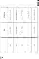
- FIG. 1 is a diagram 100 illustrating pitch scalings.
- the gate interconnect may also be referred to as "POLY" interconnect
- POLY the gate interconnect
- the gate interconnect may have a minimum pitch of g 1 (the distance between any two gate interconnects is at the minimum g 1 ).
- the gate interconnect may have a minimum pitch of g 2 (the distance between any two gate interconnects is at the minimum g 2 ).
- g 1 may be 130nm.
- a 70% scaling of the gate interconnect pitch would result in a g 2 of 90nm.
- the first metal layer M1 may have a minimum pitch of ml 1 (the distance between any two first metal layer M1 interconnects is at the minimum ml 1 ).
- the first metal layer M1 may have a minimum pitch of m1 2 (the distance between any two first metal layer M1 interconnects is at the minimum m1 2 ).
- m1 may be 90nm. A 70% scaling of the first metal layer M1 interconnect pitch would result in an m1 2 of 64nm.
- other metal layers Ma may have a minimum pitch of ma 1 (the distance between any two metal layer Ma interconnects is at the minimum ma 1 ).
- the metal layer Ma may have a minimum pitch of ma 2 (the distance between any two metal layer Ma interconnects is at the minimum ma 2 ).
- ma 1 may be 90nm.
- a 70% scaling of the metal layer Ma interconnect pitch would result in an ma 2 of 64nm.
- the Mb metal layer may have a pitch of mb.
- the Mb metal layer is higher than the Ma metal layer and may be wider than the Ma metal layer.
- the Ma metal layer may include an M2 metal layer and an M3 metal layer, and the Mb metal layer may include an M4 metal layer.
- the Ma metal layer may include an M2 metal layer, an M3 metal layer, and an M4 metal layer, and the Mb metal layer may include an M5 metal layer.
- mb is 80nm. In a 28nm manufacturing process technology, vias may have a minimum pitch of v 1 (the distance between any two vias is at the minimum v 1 ).
- the vias may have a minimum pitch of v 2 (the distance between any two vias is at the minimum v 2 ).
- v 1 may be 130nm. Maintaining a process limit due to a single patterning process (using only one mask rather than multiple masks in a double patterning process) limits the minimum pitch of any two vias. Assuming a 115nm minimum pitch (i.e., assuming v 2 is 115nm) results in an 88% scaling of the vias.
- the via pitch is not necessarily scaled similar to other elements, such as the gate and metal interconnects.
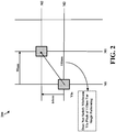
- FIG. 2 is a diagram 200 illustrating gate interconnect, metal interconnect, and via pitches.
- the two shown metal layer M1 interconnects extend in the same direction as the gate interconnects, are connected to the gate interconnects, and have the same pitch as the gate interconnects.
- Other metal layer M interconnects may have a smaller pitch, such as 64nm. Accordingly, as shown in FIG. 2 , when the gate interconnect pitch g 2 is a minimum 90nm and the metal layer M2 pitch ma 2 is a minimum 64nm, the via pitch v 2 is 110nm. If the process limit for single patterning is 115nm for the via pitch, a via pitch of 110nm would not satisfy the minimum via pitch requirements for single patterning.
- the gate interconnect, vias, and metal interconnect pitches would not align, which can cause pin access difficulty, degrade place and route efficiency, and cause a low place and route utilization (the area utilized may not be reduced to 50%).
- the scaling of the gate interconnect pitch g 2 and/or the metal layer M2 interconnect pitch ma 2 may be increased in order to satisfy the requisite scaling of the via pitch v 2 , and allow for improved pin access, place and route efficiency, and place and route utilization.
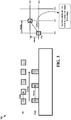
- FIG. 3 is a diagram 300 illustrating a first set of exemplary gate interconnect, metal interconnect, and via pitches.
- the scaling of the gate interconnect pitch g 2 and/or the metal layer M2 interconnect pitch ma 2 may be increased in order to satisfy the requisite scaling of the via pitch v 2 .
- the scaling of the gate interconnect pitch g 2 is increased to 73.85%.
- the via pitch V2 is 115nm, which satisfies the aforementioned 115nm via pitch limit. As shown in FIG.
- the metal layer M3 pitch may also be a minimum of 64nm.
- the least common multiple (LCM) also referred to as lowest common multiple
- the LCM of the minimum gate and metal interconnect pitches may be constrained to be less than 20 times the minimum gate interconnect pitch.
- the LCM of the minimum gate and metal interconnect pitches may be constrained to be less than 1920nm (20*96nm). In this case, the minimum gate and metal interconnect pitches of 96nm and 64nm, respectively, satisfy such a requirement.
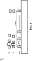
- FIG. 4 is a diagram 400 illustrating a second set of exemplary gate interconnect, metal interconnect, and via pitches.
- the minimum gate interconnect pitch may be 96nm
- the minimum metal layers M2 may be 64nm
- the minimum metal layer M3 pitch may be 72nm
- the minimum metal layer M5 pitch may be 80nm.
- the LCM of 96nm, 72nm, and 80nm is 1440nm.
- an SOC apparatus may have a plurality of gate interconnects with a minimum pitch g , a plurality of metal interconnects with a minimum pitch m , and a plurality of vias interconnecting the gate interconnects and the metal interconnects.
- the vias have a minimum pitch v .
- the pitches g , m , and v are such that g 2 + m 2 ⁇ v 2 and an LCM of g and m is less than 20 g .
- g is equal to or is approximately equal to 96nm
- m is equal to or is approximately equal to 64nm
- v is equal to or is approximately equal to 115nm.
- the LCM is 192nm, which is less than 1920nm.
- the pitches g , m, and v are constrained by the equations g 2 + m 2 ⁇ v 2 and LCM( g , m ) ⁇ 20 g .
- a via pitch v is assumed, and the gate interconnect pitch g and metal interconnect pitch m are adjusted to satisfy the equations.
- the plurality of metal interconnects are on at least one of a first interconnect level or a second interconnect level, and the vias interconnect the metal interconnects between the first interconnect level and the second interconnect level.
- the first interconnect level may be a first metal layer M1 and the second interconnect level may be a second metal layer M2.
- the SOC apparatus may further include a second plurality of metal interconnects with a minimum pitch of m 2 , where m 2 > m and the LCM of g , m , and m 2 is less than 20 g .
- g is equal to or is approximately equal to 96nm
- m is equal to or is approximately equal to 72nm
- v is equal to or is approximately equal to 115nm
- m 2 is equal to or is approximately equal to 80nm.
- the pitches g , m , m 2 , and v are constrained by the equations g 2 + m 2 > v 2 and LCM( g , m , m 2 ) ⁇ 20 g .
- a via pitch v is assumed, and the gate interconnect pitch g , metal interconnect pitch m , and metal interconnect pitch m 2 are adjusted to satisfy the equations.
- the plurality of metal interconnects may be on a third interconnect level (e.g., metal layer M3) and the second plurality of metal interconnects may be on a fifth interconnect level (e.g., metal layer M5) higher than the third interconnect level.
- the vias interconnect metal interconnects between the plurality of metal interconnects and the second plurality of metal interconnects.
- the third interconnect level may be a third metal layer M3 and the fifth interconnect level may be a fifth metal layer M5.
- FIG. 5 is a flow chart 500 of a method of operating an SOC apparatus.
- a current is flowed through a plurality of gate interconnects with a minimum pitch g .
- a current is flowed through a plurality of metal interconnects with a minimum pitch m .
- a current is flowed through a plurality of vias interconnecting the gate interconnects and the metal interconnects.
- the vias have a minimum pitch v .
- the pitches of the gate interconnects, metal interconnects, and vias satisfy g 2 + m 2 > v 2 .
- an LCM of g and m is less than 20 g .
- the plurality of metal interconnects may be on at least one of a first interconnect level or a second interconnect level, and the vias may interconnect the metal interconnects between the first interconnect level and the second interconnect level.
- the first interconnect level may be a first metal layer and the second interconnect level may be a second metal layer.
- a current is flowed through a second plurality of metal interconnects with a minimum pitch of m 2 , where m 2 > m and the LCM of g , m , and m 2 is less than 20 g .
- the plurality of metal interconnects may be on a third interconnect level and the second plurality of metal interconnects may be on a fifth interconnect level.
- the vias may interconnect metal interconnects between the plurality of metal interconnects and the second plurality of metal interconnects.
- the third interconnect level may be a third metal layer and the fifth interconnect level may be a fifth metal layer.
- an SOC apparatus includes means for flowing a current through a plurality of gate interconnects with a minimum pitch g , means for flowing a current through a plurality of metal interconnects with a minimum pitch m , and means for flowing a current through a plurality of vias interconnecting the gate interconnects and the metal interconnects.
- the vias having a minimum pitch v , g 2 + m 2 > v 2 , and an LCM of g and m is less than 20 g .
- the means for flowing a current through a plurality of gate interconnects is the plurality of gate interconnects
- the means for flowing a current through a plurality of metal interconnects is the plurality of metal interconnects
- the means for flowing a current through a plurality of vias is the plurality of vias.
- the SOC apparatus may further include means for flowing a current through a second plurality of metal interconnects with a minimum pitch of m 2 , where m 2 > m and the LCM of g , m , and m 2 is less than 20 g .
- the means for flowing a current through a second plurality of metal interconnects is the second plurality of metal interconnects.
- x % pitch scaling may be used for some interconnects.
- the minimum pitch scaling may be determined based on minimum via pitch limits. Such a scaling may provide improved cost, power, and performance benefits over an x % pitch scaling for all interconnects.
- Combinations such as “at least one of A, B, or C,” “at least one of A, B, and C,” and “A, B, C, or any combination thereof' include any combination of A, B, and/or C, and may include multiples of A, multiples of B, or multiples of C.
- combinations such as “at least one of A, B, or C,” “at least one of A, B, and C,” and “A, B, C, or any combination thereof” may be A only, B only, C only, A and B, A and C, B and C, or A and B and C, where any such combinations may contain one or more member or members of A, B, or C.
Landscapes
- Engineering & Computer Science (AREA)
- Physics & Mathematics (AREA)
- Microelectronics & Electronic Packaging (AREA)
- Power Engineering (AREA)
- Condensed Matter Physics & Semiconductors (AREA)
- General Physics & Mathematics (AREA)
- Computer Hardware Design (AREA)
- Manufacturing & Machinery (AREA)
- Geometry (AREA)
- Design And Manufacture Of Integrated Circuits (AREA)
- General Engineering & Computer Science (AREA)
- Internal Circuitry In Semiconductor Integrated Circuit Devices (AREA)
Applications Claiming Priority (3)
| Application Number | Priority Date | Filing Date | Title |
|---|---|---|---|
| US201361858567P | 2013-07-25 | 2013-07-25 | |
| US14/338,229 US9331016B2 (en) | 2013-07-25 | 2014-07-22 | SOC design with critical technology pitch alignment |
| PCT/US2014/047834 WO2015013415A1 (en) | 2013-07-25 | 2014-07-23 | A soc design with critical technology pitch alignment |
Publications (2)
| Publication Number | Publication Date |
|---|---|
| EP3025370A1 EP3025370A1 (en) | 2016-06-01 |
| EP3025370B1 true EP3025370B1 (en) | 2017-02-01 |
Family
ID=52389817
Family Applications (1)
| Application Number | Title | Priority Date | Filing Date |
|---|---|---|---|
| EP14758188.8A Active EP3025370B1 (en) | 2013-07-25 | 2014-07-23 | A soc design with critical technology pitch alignment |
Country Status (7)
| Country | Link |
|---|---|
| US (1) | US9331016B2 (enExample) |
| EP (1) | EP3025370B1 (enExample) |
| JP (1) | JP6208350B2 (enExample) |
| KR (1) | KR101820813B1 (enExample) |
| CN (1) | CN105453263B (enExample) |
| CA (1) | CA2917642A1 (enExample) |
| WO (1) | WO2015013415A1 (enExample) |
Families Citing this family (8)
| Publication number | Priority date | Publication date | Assignee | Title |
|---|---|---|---|---|
| US9391056B2 (en) * | 2013-08-16 | 2016-07-12 | Taiwan Semiconductor Manufacturing Company, Ltd. | Mask optimization for multi-layer contacts |
| US9972624B2 (en) | 2013-08-23 | 2018-05-15 | Qualcomm Incorporated | Layout construction for addressing electromigration |
| US9786663B2 (en) | 2013-08-23 | 2017-10-10 | Qualcomm Incorporated | Layout construction for addressing electromigration |
| KR20250008983A (ko) * | 2017-06-20 | 2025-01-16 | 인텔 코포레이션 | 메모리 비트 셀들을 위한 내부 노드 점퍼 |
| US10903239B2 (en) | 2017-07-28 | 2021-01-26 | Taiwan Semiconductor Manufacturing Co., Ltd. | Integrated circuit device with improved layout |
| DE102018118053A1 (de) | 2017-07-28 | 2019-01-31 | Taiwan Semiconductor Manufacturing Co., Ltd. | Integrierte Schaltungsvorrichtung mit verbessertem Layout |
| US10916498B2 (en) | 2018-03-28 | 2021-02-09 | Taiwan Semiconductor Manufacturing Co., Ltd. | Interconnect structure for logic circuit |
| KR102842752B1 (ko) | 2019-12-04 | 2025-08-04 | 삼성전자주식회사 | 반도체 장치 |
Family Cites Families (25)
| Publication number | Priority date | Publication date | Assignee | Title |
|---|---|---|---|---|
| JP3241106B2 (ja) * | 1992-07-17 | 2001-12-25 | 株式会社東芝 | ダイナミック型半導体記憶装置及びその製造方法 |
| US5508938A (en) | 1992-08-13 | 1996-04-16 | Fujitsu Limited | Special interconnect layer employing offset trace layout for advanced multi-chip module packages |
| US5471093A (en) | 1994-10-28 | 1995-11-28 | Advanced Micro Devices, Inc. | Pseudo-low dielectric constant technology |
| US6207479B1 (en) * | 1999-06-14 | 2001-03-27 | Taiwan Semiconductor Manufacturing Co., Ltd. | Place and route method for integrated circuit design |
| US7398498B2 (en) * | 2001-08-23 | 2008-07-08 | Cadence Design Systems, Inc. | Method and apparatus for storing routes for groups of related net configurations |
| US6618846B2 (en) * | 2001-08-31 | 2003-09-09 | Synopsys, Inc. | Estimating capacitance effects in integrated circuits using congestion estimations |
| US6735753B2 (en) | 2002-10-04 | 2004-05-11 | Oki Electric Industry Co., Ltd. | Method of fabricating a semiconductor device having a multilevel interconnections |
| US7084476B2 (en) * | 2004-02-26 | 2006-08-01 | International Business Machines Corp. | Integrated circuit logic with self compensating block delays |
| US7414275B2 (en) * | 2005-06-24 | 2008-08-19 | International Business Machines Corporation | Multi-level interconnections for an integrated circuit chip |
| US7492013B2 (en) * | 2005-06-27 | 2009-02-17 | International Business Machines Corporation | Systems and arrangements to interconnect components of a semiconductor device |
| JP4791855B2 (ja) * | 2006-02-28 | 2011-10-12 | 株式会社東芝 | 半導体記憶装置 |
| US7932545B2 (en) | 2006-03-09 | 2011-04-26 | Tela Innovations, Inc. | Semiconductor device and associated layouts including gate electrode level region having arrangement of six linear conductive segments with side-to-side spacing less than 360 nanometers |
| US7446352B2 (en) * | 2006-03-09 | 2008-11-04 | Tela Innovations, Inc. | Dynamic array architecture |
| US7557449B2 (en) | 2006-09-07 | 2009-07-07 | Taiwan Semiconductor Manufacturing Company, Ltd. | Flexible via design to improve reliability |
| JP2008171977A (ja) * | 2007-01-11 | 2008-07-24 | Matsushita Electric Ind Co Ltd | 半導体集積回路のレイアウト構造 |
| US7888705B2 (en) * | 2007-08-02 | 2011-02-15 | Tela Innovations, Inc. | Methods for defining dynamic array section with manufacturing assurance halo and apparatus implementing the same |
| US7737554B2 (en) * | 2007-06-25 | 2010-06-15 | Taiwan Semiconductor Manufacturing Company, Ltd. | Pitch by splitting bottom metallization layer |
| WO2010019441A1 (en) | 2008-08-14 | 2010-02-18 | Nantero, Inc. | Nonvolatile nanotube programmable logic devices and field programmable gate array |
| US8198655B1 (en) * | 2009-04-27 | 2012-06-12 | Carnegie Mellon University | Regular pattern arrays for memory and logic on a semiconductor substrate |
| US8174868B2 (en) | 2009-09-30 | 2012-05-08 | Taiwan Semiconductor Manufacturing Co., Ltd. | Embedded SRAM structure and chip |
| WO2012053125A1 (ja) * | 2010-10-21 | 2012-04-26 | パナソニック株式会社 | 半導体装置 |
| JP6066542B2 (ja) | 2010-11-18 | 2017-01-25 | ピーエスフォー ルクスコ エスエイアールエルPS4 Luxco S.a.r.l. | 半導体装置 |
| US9112000B2 (en) * | 2011-09-19 | 2015-08-18 | Texas Instruments Incorporated | Method for ensuring DPT compliance for auto-routed via layers |
| US8860141B2 (en) * | 2012-01-06 | 2014-10-14 | International Business Machines Corporation | Layout to minimize FET variation in small dimension photolithography |
| US8863048B1 (en) * | 2013-03-15 | 2014-10-14 | Cadence Design Systems, Inc. | Methods, systems, and articles of manufacture for implementing multiple-patterning-aware correct-by-construction layout processing for an electronic design |
-
2014
- 2014-07-22 US US14/338,229 patent/US9331016B2/en active Active
- 2014-07-23 JP JP2016529862A patent/JP6208350B2/ja active Active
- 2014-07-23 WO PCT/US2014/047834 patent/WO2015013415A1/en not_active Ceased
- 2014-07-23 EP EP14758188.8A patent/EP3025370B1/en active Active
- 2014-07-23 CN CN201480041649.6A patent/CN105453263B/zh active Active
- 2014-07-23 KR KR1020167003858A patent/KR101820813B1/ko not_active Expired - Fee Related
- 2014-07-23 CA CA2917642A patent/CA2917642A1/en not_active Abandoned
Non-Patent Citations (1)
| Title |
|---|
| None * |
Also Published As
| Publication number | Publication date |
|---|---|
| EP3025370A1 (en) | 2016-06-01 |
| US9331016B2 (en) | 2016-05-03 |
| US20150028495A1 (en) | 2015-01-29 |
| CN105453263A (zh) | 2016-03-30 |
| JP2016527724A (ja) | 2016-09-08 |
| WO2015013415A1 (en) | 2015-01-29 |
| JP6208350B2 (ja) | 2017-10-04 |
| CN105453263B (zh) | 2021-03-12 |
| CA2917642A1 (en) | 2015-01-29 |
| KR101820813B1 (ko) | 2018-01-22 |
| KR20160034338A (ko) | 2016-03-29 |
Similar Documents
| Publication | Publication Date | Title |
|---|---|---|
| EP3025370B1 (en) | A soc design with critical technology pitch alignment | |
| US10593700B2 (en) | Standard cell architecture with M1 layer unidirectional routing | |
| US9502351B1 (en) | Multiple split rail standard cell library architecture | |
| US9520358B2 (en) | Via structure for optimizing signal porosity | |
| US11437375B2 (en) | Layout construction for addressing electromigration | |
| DE112016007567T5 (de) | Gehäusesubstrat mit hochdichte-zwischenverbindungsschicht mit säulen- und via-verbindungen zur fan-out-skalierung | |
| US11508725B2 (en) | Layout construction for addressing electromigration | |
| US12341098B2 (en) | Metal patterning for internal cell routing | |
| US20150262936A1 (en) | Multi supply cell arrays for low power designs | |
| CN106165097A (zh) | 用于小面积数字soc的自适应标准单元架构和布局技术 | |
| US9640480B2 (en) | Cross-couple in multi-height sequential cells for uni-directional M1 | |
| KR101898510B1 (ko) | 고밀도 안테나 보호 다이오드를 위한 회로 및 레이아웃 | |
| EP4338204B9 (en) | Dummy cell and tap cell layout structure | |
| CN107463724B (zh) | 用于设计和制造半导体器件的方法以及相应的半导体器件 | |
| US7382053B2 (en) | Power supply wiring structure | |
| CN107078121B (zh) | Io功率总线网格结构设计 | |
| US20180269148A1 (en) | Semiconductor device, layout pattern and method for manufacturing an integrated circuit | |
| KR20230002969A (ko) | 인접한 특징부들 사이에 전도성 파이프를 형성하는 방법 및 인접한 특징부들 사이에 전도성 파이프를 갖는 집적 조립체 |
Legal Events
| Date | Code | Title | Description |
|---|---|---|---|
| PUAI | Public reference made under article 153(3) epc to a published international application that has entered the european phase |
Free format text: ORIGINAL CODE: 0009012 |
|
| 17P | Request for examination filed |
Effective date: 20160222 |
|
| AK | Designated contracting states |
Kind code of ref document: A1 Designated state(s): AL AT BE BG CH CY CZ DE DK EE ES FI FR GB GR HR HU IE IS IT LI LT LU LV MC MK MT NL NO PL PT RO RS SE SI SK SM TR |
|
| AX | Request for extension of the european patent |
Extension state: BA ME |
|
| GRAP | Despatch of communication of intention to grant a patent |
Free format text: ORIGINAL CODE: EPIDOSNIGR1 |
|
| RIC1 | Information provided on ipc code assigned before grant |
Ipc: H01L 21/768 20060101ALI20160721BHEP Ipc: H01L 23/528 20060101ALI20160721BHEP Ipc: H01L 27/02 20060101AFI20160721BHEP Ipc: H01L 23/498 20060101ALI20160721BHEP Ipc: H01L 23/522 20060101ALI20160721BHEP |
|
| INTG | Intention to grant announced |
Effective date: 20160818 |
|
| DAX | Request for extension of the european patent (deleted) | ||
| GRAS | Grant fee paid |
Free format text: ORIGINAL CODE: EPIDOSNIGR3 |
|
| GRAA | (expected) grant |
Free format text: ORIGINAL CODE: 0009210 |
|
| AK | Designated contracting states |
Kind code of ref document: B1 Designated state(s): AL AT BE BG CH CY CZ DE DK EE ES FI FR GB GR HR HU IE IS IT LI LT LU LV MC MK MT NL NO PL PT RO RS SE SI SK SM TR |
|
| REG | Reference to a national code |
Ref country code: GB Ref legal event code: FG4D |
|
| REG | Reference to a national code |
Ref country code: CH Ref legal event code: EP Ref country code: AT Ref legal event code: REF Ref document number: 866207 Country of ref document: AT Kind code of ref document: T Effective date: 20170215 |
|
| REG | Reference to a national code |
Ref country code: FR Ref legal event code: PLFP Year of fee payment: 4 |
|
| REG | Reference to a national code |
Ref country code: IE Ref legal event code: FG4D |
|
| REG | Reference to a national code |
Ref country code: DE Ref legal event code: R096 Ref document number: 602014006652 Country of ref document: DE |
|
| PGFP | Annual fee paid to national office [announced via postgrant information from national office to epo] |
Ref country code: FR Payment date: 20170218 Year of fee payment: 4 |
|
| REG | Reference to a national code |
Ref country code: NL Ref legal event code: MP Effective date: 20170201 |
|
| REG | Reference to a national code |
Ref country code: LT Ref legal event code: MG4D |
|
| REG | Reference to a national code |
Ref country code: AT Ref legal event code: MK05 Ref document number: 866207 Country of ref document: AT Kind code of ref document: T Effective date: 20170201 |
|
| PG25 | Lapsed in a contracting state [announced via postgrant information from national office to epo] |
Ref country code: GR Free format text: LAPSE BECAUSE OF FAILURE TO SUBMIT A TRANSLATION OF THE DESCRIPTION OR TO PAY THE FEE WITHIN THE PRESCRIBED TIME-LIMIT Effective date: 20170502 Ref country code: NO Free format text: LAPSE BECAUSE OF FAILURE TO SUBMIT A TRANSLATION OF THE DESCRIPTION OR TO PAY THE FEE WITHIN THE PRESCRIBED TIME-LIMIT Effective date: 20170501 Ref country code: HR Free format text: LAPSE BECAUSE OF FAILURE TO SUBMIT A TRANSLATION OF THE DESCRIPTION OR TO PAY THE FEE WITHIN THE PRESCRIBED TIME-LIMIT Effective date: 20170201 Ref country code: FI Free format text: LAPSE BECAUSE OF FAILURE TO SUBMIT A TRANSLATION OF THE DESCRIPTION OR TO PAY THE FEE WITHIN THE PRESCRIBED TIME-LIMIT Effective date: 20170201 Ref country code: IS Free format text: LAPSE BECAUSE OF FAILURE TO SUBMIT A TRANSLATION OF THE DESCRIPTION OR TO PAY THE FEE WITHIN THE PRESCRIBED TIME-LIMIT Effective date: 20170601 Ref country code: LT Free format text: LAPSE BECAUSE OF FAILURE TO SUBMIT A TRANSLATION OF THE DESCRIPTION OR TO PAY THE FEE WITHIN THE PRESCRIBED TIME-LIMIT Effective date: 20170201 |
|
| PG25 | Lapsed in a contracting state [announced via postgrant information from national office to epo] |
Ref country code: AT Free format text: LAPSE BECAUSE OF FAILURE TO SUBMIT A TRANSLATION OF THE DESCRIPTION OR TO PAY THE FEE WITHIN THE PRESCRIBED TIME-LIMIT Effective date: 20170201 Ref country code: NL Free format text: LAPSE BECAUSE OF NON-PAYMENT OF DUE FEES Effective date: 20170201 Ref country code: RS Free format text: LAPSE BECAUSE OF FAILURE TO SUBMIT A TRANSLATION OF THE DESCRIPTION OR TO PAY THE FEE WITHIN THE PRESCRIBED TIME-LIMIT Effective date: 20170201 Ref country code: LV Free format text: LAPSE BECAUSE OF FAILURE TO SUBMIT A TRANSLATION OF THE DESCRIPTION OR TO PAY THE FEE WITHIN THE PRESCRIBED TIME-LIMIT Effective date: 20170201 Ref country code: SE Free format text: LAPSE BECAUSE OF FAILURE TO SUBMIT A TRANSLATION OF THE DESCRIPTION OR TO PAY THE FEE WITHIN THE PRESCRIBED TIME-LIMIT Effective date: 20170201 Ref country code: ES Free format text: LAPSE BECAUSE OF FAILURE TO SUBMIT A TRANSLATION OF THE DESCRIPTION OR TO PAY THE FEE WITHIN THE PRESCRIBED TIME-LIMIT Effective date: 20170201 Ref country code: BG Free format text: LAPSE BECAUSE OF FAILURE TO SUBMIT A TRANSLATION OF THE DESCRIPTION OR TO PAY THE FEE WITHIN THE PRESCRIBED TIME-LIMIT Effective date: 20170501 Ref country code: PL Free format text: LAPSE BECAUSE OF FAILURE TO SUBMIT A TRANSLATION OF THE DESCRIPTION OR TO PAY THE FEE WITHIN THE PRESCRIBED TIME-LIMIT Effective date: 20170201 Ref country code: PT Free format text: LAPSE BECAUSE OF FAILURE TO SUBMIT A TRANSLATION OF THE DESCRIPTION OR TO PAY THE FEE WITHIN THE PRESCRIBED TIME-LIMIT Effective date: 20170601 |
|
| PG25 | Lapsed in a contracting state [announced via postgrant information from national office to epo] |
Ref country code: CZ Free format text: LAPSE BECAUSE OF FAILURE TO SUBMIT A TRANSLATION OF THE DESCRIPTION OR TO PAY THE FEE WITHIN THE PRESCRIBED TIME-LIMIT Effective date: 20170201 Ref country code: IT Free format text: LAPSE BECAUSE OF FAILURE TO SUBMIT A TRANSLATION OF THE DESCRIPTION OR TO PAY THE FEE WITHIN THE PRESCRIBED TIME-LIMIT Effective date: 20170201 Ref country code: EE Free format text: LAPSE BECAUSE OF FAILURE TO SUBMIT A TRANSLATION OF THE DESCRIPTION OR TO PAY THE FEE WITHIN THE PRESCRIBED TIME-LIMIT Effective date: 20170201 Ref country code: SK Free format text: LAPSE BECAUSE OF FAILURE TO SUBMIT A TRANSLATION OF THE DESCRIPTION OR TO PAY THE FEE WITHIN THE PRESCRIBED TIME-LIMIT Effective date: 20170201 Ref country code: RO Free format text: LAPSE BECAUSE OF FAILURE TO SUBMIT A TRANSLATION OF THE DESCRIPTION OR TO PAY THE FEE WITHIN THE PRESCRIBED TIME-LIMIT Effective date: 20170201 |
|
| REG | Reference to a national code |
Ref country code: DE Ref legal event code: R097 Ref document number: 602014006652 Country of ref document: DE |
|
| PG25 | Lapsed in a contracting state [announced via postgrant information from national office to epo] |
Ref country code: SM Free format text: LAPSE BECAUSE OF FAILURE TO SUBMIT A TRANSLATION OF THE DESCRIPTION OR TO PAY THE FEE WITHIN THE PRESCRIBED TIME-LIMIT Effective date: 20170201 Ref country code: DK Free format text: LAPSE BECAUSE OF FAILURE TO SUBMIT A TRANSLATION OF THE DESCRIPTION OR TO PAY THE FEE WITHIN THE PRESCRIBED TIME-LIMIT Effective date: 20170201 |
|
| PLBE | No opposition filed within time limit |
Free format text: ORIGINAL CODE: 0009261 |
|
| STAA | Information on the status of an ep patent application or granted ep patent |
Free format text: STATUS: NO OPPOSITION FILED WITHIN TIME LIMIT |
|
| 26N | No opposition filed |
Effective date: 20171103 |
|
| PG25 | Lapsed in a contracting state [announced via postgrant information from national office to epo] |
Ref country code: SI Free format text: LAPSE BECAUSE OF FAILURE TO SUBMIT A TRANSLATION OF THE DESCRIPTION OR TO PAY THE FEE WITHIN THE PRESCRIBED TIME-LIMIT Effective date: 20170201 |
|
| REG | Reference to a national code |
Ref country code: CH Ref legal event code: PL |
|
| REG | Reference to a national code |
Ref country code: IE Ref legal event code: MM4A |
|
| PG25 | Lapsed in a contracting state [announced via postgrant information from national office to epo] |
Ref country code: CH Free format text: LAPSE BECAUSE OF NON-PAYMENT OF DUE FEES Effective date: 20170731 Ref country code: IE Free format text: LAPSE BECAUSE OF NON-PAYMENT OF DUE FEES Effective date: 20170723 Ref country code: LI Free format text: LAPSE BECAUSE OF NON-PAYMENT OF DUE FEES Effective date: 20170731 |
|
| REG | Reference to a national code |
Ref country code: BE Ref legal event code: MM Effective date: 20170731 |
|
| PG25 | Lapsed in a contracting state [announced via postgrant information from national office to epo] |
Ref country code: LU Free format text: LAPSE BECAUSE OF NON-PAYMENT OF DUE FEES Effective date: 20170723 |
|
| PG25 | Lapsed in a contracting state [announced via postgrant information from national office to epo] |
Ref country code: BE Free format text: LAPSE BECAUSE OF NON-PAYMENT OF DUE FEES Effective date: 20170731 |
|
| PG25 | Lapsed in a contracting state [announced via postgrant information from national office to epo] |
Ref country code: MT Free format text: LAPSE BECAUSE OF NON-PAYMENT OF DUE FEES Effective date: 20170723 |
|
| GBPC | Gb: european patent ceased through non-payment of renewal fee |
Effective date: 20180723 |
|
| PG25 | Lapsed in a contracting state [announced via postgrant information from national office to epo] |
Ref country code: GB Free format text: LAPSE BECAUSE OF NON-PAYMENT OF DUE FEES Effective date: 20180723 Ref country code: FR Free format text: LAPSE BECAUSE OF NON-PAYMENT OF DUE FEES Effective date: 20180731 |
|
| PG25 | Lapsed in a contracting state [announced via postgrant information from national office to epo] |
Ref country code: MC Free format text: LAPSE BECAUSE OF FAILURE TO SUBMIT A TRANSLATION OF THE DESCRIPTION OR TO PAY THE FEE WITHIN THE PRESCRIBED TIME-LIMIT Effective date: 20170201 Ref country code: HU Free format text: LAPSE BECAUSE OF FAILURE TO SUBMIT A TRANSLATION OF THE DESCRIPTION OR TO PAY THE FEE WITHIN THE PRESCRIBED TIME-LIMIT; INVALID AB INITIO Effective date: 20140723 |
|
| PG25 | Lapsed in a contracting state [announced via postgrant information from national office to epo] |
Ref country code: CY Free format text: LAPSE BECAUSE OF FAILURE TO SUBMIT A TRANSLATION OF THE DESCRIPTION OR TO PAY THE FEE WITHIN THE PRESCRIBED TIME-LIMIT Effective date: 20170201 |
|
| PG25 | Lapsed in a contracting state [announced via postgrant information from national office to epo] |
Ref country code: MK Free format text: LAPSE BECAUSE OF FAILURE TO SUBMIT A TRANSLATION OF THE DESCRIPTION OR TO PAY THE FEE WITHIN THE PRESCRIBED TIME-LIMIT Effective date: 20170201 |
|
| PG25 | Lapsed in a contracting state [announced via postgrant information from national office to epo] |
Ref country code: TR Free format text: LAPSE BECAUSE OF FAILURE TO SUBMIT A TRANSLATION OF THE DESCRIPTION OR TO PAY THE FEE WITHIN THE PRESCRIBED TIME-LIMIT Effective date: 20170201 |
|
| PG25 | Lapsed in a contracting state [announced via postgrant information from national office to epo] |
Ref country code: AL Free format text: LAPSE BECAUSE OF FAILURE TO SUBMIT A TRANSLATION OF THE DESCRIPTION OR TO PAY THE FEE WITHIN THE PRESCRIBED TIME-LIMIT Effective date: 20170201 |
|
| REG | Reference to a national code |
Ref country code: DE Ref legal event code: R079 Ref document number: 602014006652 Country of ref document: DE Free format text: PREVIOUS MAIN CLASS: H01L0027020000 Ipc: H10D0089000000 |
|
| PGFP | Annual fee paid to national office [announced via postgrant information from national office to epo] |
Ref country code: DE Payment date: 20250616 Year of fee payment: 12 |