EP3025057B1 - Sous-ensemble oscillo-rotatif et dispositif pour multiplexage fluidique et pompage volumétrique co-intégrés d'un fluide - Google Patents
Sous-ensemble oscillo-rotatif et dispositif pour multiplexage fluidique et pompage volumétrique co-intégrés d'un fluide Download PDFInfo
- Publication number
- EP3025057B1 EP3025057B1 EP14738555.3A EP14738555A EP3025057B1 EP 3025057 B1 EP3025057 B1 EP 3025057B1 EP 14738555 A EP14738555 A EP 14738555A EP 3025057 B1 EP3025057 B1 EP 3025057B1
- Authority
- EP
- European Patent Office
- Prior art keywords
- proximal
- distal
- ducts
- fluid
- duct
- Prior art date
- Legal status (The legal status is an assumption and is not a legal conclusion. Google has not performed a legal analysis and makes no representation as to the accuracy of the status listed.)
- Not-in-force
Links
Images


Classifications
-
- F—MECHANICAL ENGINEERING; LIGHTING; HEATING; WEAPONS; BLASTING
- F04—POSITIVE - DISPLACEMENT MACHINES FOR LIQUIDS; PUMPS FOR LIQUIDS OR ELASTIC FLUIDS
- F04B—POSITIVE-DISPLACEMENT MACHINES FOR LIQUIDS; PUMPS
- F04B7/00—Piston machines or pumps characterised by having positively-driven valving
- F04B7/04—Piston machines or pumps characterised by having positively-driven valving in which the valving is performed by pistons and cylinders coacting to open and close intake or outlet ports
- F04B7/06—Piston machines or pumps characterised by having positively-driven valving in which the valving is performed by pistons and cylinders coacting to open and close intake or outlet ports the pistons and cylinders being relatively reciprocated and rotated
-
- F—MECHANICAL ENGINEERING; LIGHTING; HEATING; WEAPONS; BLASTING
- F04—POSITIVE - DISPLACEMENT MACHINES FOR LIQUIDS; PUMPS FOR LIQUIDS OR ELASTIC FLUIDS
- F04B—POSITIVE-DISPLACEMENT MACHINES FOR LIQUIDS; PUMPS
- F04B13/00—Pumps specially modified to deliver fixed or variable measured quantities
- F04B13/02—Pumps specially modified to deliver fixed or variable measured quantities of two or more fluids at the same time
-
- F—MECHANICAL ENGINEERING; LIGHTING; HEATING; WEAPONS; BLASTING
- F04—POSITIVE - DISPLACEMENT MACHINES FOR LIQUIDS; PUMPS FOR LIQUIDS OR ELASTIC FLUIDS
- F04B—POSITIVE-DISPLACEMENT MACHINES FOR LIQUIDS; PUMPS
- F04B53/00—Component parts, details or accessories not provided for in, or of interest apart from, groups F04B1/00 - F04B23/00 or F04B39/00 - F04B47/00
- F04B53/14—Pistons, piston-rods or piston-rod connections
- F04B53/148—Pistons, piston-rods or piston-rod connections the piston being provided with channels which are coacting with the cylinder and are used as a distribution member for another piston-cylinder unit
-
- F—MECHANICAL ENGINEERING; LIGHTING; HEATING; WEAPONS; BLASTING
- F04—POSITIVE - DISPLACEMENT MACHINES FOR LIQUIDS; PUMPS FOR LIQUIDS OR ELASTIC FLUIDS
- F04B—POSITIVE-DISPLACEMENT MACHINES FOR LIQUIDS; PUMPS
- F04B53/00—Component parts, details or accessories not provided for in, or of interest apart from, groups F04B1/00 - F04B23/00 or F04B39/00 - F04B47/00
- F04B53/16—Casings; Cylinders; Cylinder liners or heads; Fluid connections
-
- F—MECHANICAL ENGINEERING; LIGHTING; HEATING; WEAPONS; BLASTING
- F04—POSITIVE - DISPLACEMENT MACHINES FOR LIQUIDS; PUMPS FOR LIQUIDS OR ELASTIC FLUIDS
- F04B—POSITIVE-DISPLACEMENT MACHINES FOR LIQUIDS; PUMPS
- F04B7/00—Piston machines or pumps characterised by having positively-driven valving
- F04B7/0003—Piston machines or pumps characterised by having positively-driven valving the distribution member forming both the inlet and discharge distributor for one single pumping chamber
- F04B7/0007—Piston machines or pumps characterised by having positively-driven valving the distribution member forming both the inlet and discharge distributor for one single pumping chamber and having a rotating movement
-
- F—MECHANICAL ENGINEERING; LIGHTING; HEATING; WEAPONS; BLASTING
- F04—POSITIVE - DISPLACEMENT MACHINES FOR LIQUIDS; PUMPS FOR LIQUIDS OR ELASTIC FLUIDS
- F04B—POSITIVE-DISPLACEMENT MACHINES FOR LIQUIDS; PUMPS
- F04B9/00—Piston machines or pumps characterised by the driving or driven means to or from their working members
- F04B9/02—Piston machines or pumps characterised by the driving or driven means to or from their working members the means being mechanical
- F04B9/04—Piston machines or pumps characterised by the driving or driven means to or from their working members the means being mechanical the means being cams, eccentrics or pin-and-slot mechanisms
- F04B9/047—Piston machines or pumps characterised by the driving or driven means to or from their working members the means being mechanical the means being cams, eccentrics or pin-and-slot mechanisms the means being pin-and-slot mechanisms
-
- F—MECHANICAL ENGINEERING; LIGHTING; HEATING; WEAPONS; BLASTING
- F16—ENGINEERING ELEMENTS AND UNITS; GENERAL MEASURES FOR PRODUCING AND MAINTAINING EFFECTIVE FUNCTIONING OF MACHINES OR INSTALLATIONS; THERMAL INSULATION IN GENERAL
- F16K—VALVES; TAPS; COCKS; ACTUATING-FLOATS; DEVICES FOR VENTING OR AERATING
- F16K11/00—Multiple-way valves, e.g. mixing valves; Pipe fittings incorporating such valves
- F16K11/02—Multiple-way valves, e.g. mixing valves; Pipe fittings incorporating such valves with all movable sealing faces moving as one unit
- F16K11/06—Multiple-way valves, e.g. mixing valves; Pipe fittings incorporating such valves with all movable sealing faces moving as one unit comprising only sliding valves, i.e. sliding closure elements
- F16K11/072—Multiple-way valves, e.g. mixing valves; Pipe fittings incorporating such valves with all movable sealing faces moving as one unit comprising only sliding valves, i.e. sliding closure elements with pivoted closure members
- F16K11/076—Multiple-way valves, e.g. mixing valves; Pipe fittings incorporating such valves with all movable sealing faces moving as one unit comprising only sliding valves, i.e. sliding closure elements with pivoted closure members with sealing faces shaped as surfaces of solids of revolution
-
- F—MECHANICAL ENGINEERING; LIGHTING; HEATING; WEAPONS; BLASTING
- F16—ENGINEERING ELEMENTS AND UNITS; GENERAL MEASURES FOR PRODUCING AND MAINTAINING EFFECTIVE FUNCTIONING OF MACHINES OR INSTALLATIONS; THERMAL INSULATION IN GENERAL
- F16K—VALVES; TAPS; COCKS; ACTUATING-FLOATS; DEVICES FOR VENTING OR AERATING
- F16K11/00—Multiple-way valves, e.g. mixing valves; Pipe fittings incorporating such valves
- F16K11/02—Multiple-way valves, e.g. mixing valves; Pipe fittings incorporating such valves with all movable sealing faces moving as one unit
- F16K11/08—Multiple-way valves, e.g. mixing valves; Pipe fittings incorporating such valves with all movable sealing faces moving as one unit comprising only taps or cocks
- F16K11/085—Multiple-way valves, e.g. mixing valves; Pipe fittings incorporating such valves with all movable sealing faces moving as one unit comprising only taps or cocks with cylindrical plug
- F16K11/0856—Multiple-way valves, e.g. mixing valves; Pipe fittings incorporating such valves with all movable sealing faces moving as one unit comprising only taps or cocks with cylindrical plug having all the connecting conduits situated in more than one plane perpendicular to the axis of the plug
Definitions
- the invention generally relates to an oscillating-rotary subassembly for volumetric pumping of a fluid and an oscillating-rotary pumping device incorporating a compact fluidic multiplexing means.
- pumping devices for production and / or reconstitution (liquid-solid or liquid-liquid mixtures) and / or administration (injection, infusion, oral, spray, etc.) is known, in particular for medical, aesthetic, veterinary applications, for which they allow the supply of fluid for example from one or more administration devices.
- the pumping devices comprise a body provided with ducts opening into a cavity receiving a piston with which it defines a working chamber.
- the piston is for example displaced in an oscillatory-rotary movement putting the radial ducts successively in fluid communication with the working chamber to suck and then discharge the fluid.
- the fluidic configuration of such pumping devices is fixed, namely that the conduits are either conducting (allowing fluid communication) or non-conducting (not permitting fluid communication) depending on the position of the piston.
- the documents DE 36 30 528 and DE 44 09 994 also describe devices for volumetric pumping of a fluid.
- the object of the invention is to overcome this disadvantage by proposing an oscillation-rotary subassembly for volumetric pumping and an oscillating-rotary pumping device for multiplying the external conduits to the subset and rendering said conduits selectively, passing or no passing, and thus to increase the possibilities of fluidic transfer configurations between these conduits.
- the subject of the invention is an oscillating-rotary subassembly for volumetric pumping of a fluid, comprising a hollow body of longitudinal axis defining at least one cavity and the wall of which is traversed by conduits, a piston housed in the cavity with which it defines a working chamber, the piston having on its periphery at least one recess in fluid communication with the working chamber, the piston being adapted to be driven in a rotational-rotary movement relative to the body so as to be angularly movable between different operating positions in each of which the recess is or not facing at least one of the ducts and in translation so as to vary the volume of the working chamber to successively suck and then push back the fluid, characterized in that the oscillating-rotational subassembly comprises a movable sleeve between the piston and the body, in that the wall of the jacket is traversed by the orifices, inserted radially between the piston and the body, and adapted to adopt in
- the idea underlying the invention is to provide a perforated liner, disposed between the body and the piston, and whose mobility relative to the body allows to seal or not the ducts so that they are selectively passing or not depending on the position of the jacket and thus propose different fluidic configurations.
- the mobility of the chamber may be angular or longitudinal or an angular and longitudinal combination.
- distal is used in the following for any element oriented in the direction of introduction of the piston into the body and the term “proximal” for any element oriented opposite .
- the distal and proximal directions are schematized respectively by the arrows D and P, in particular on the figure 1 .
- references CPi, CRi, CSi, CDi are used for conduits in general, the index i being replaced by a number to designate a specific conduit.
- the references OPi, ORi, OSi, ODi are used for the orifices in general, the index i being replaced by a number to designate a specific orifice
- the invention extends to an oscillation-rotating pump device for fluid, characterized in that it comprises drive means, a rotary-oscillation subassembly for pumping a fluid as described and means for removable mechanical coupling to mechanically connect the drive means to said piston in a removable manner.
- the oscillation-rotary pumping device may comprise an oscillating-rotary sub-assembly, the liner of which is provided with drive shapes intended to be coupled to adjustment means, and adjustment means able to urge the training forms for change the position of the shirt relative to the body.
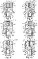
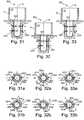
- the oscillating-rotational subassembly 1 comprises a body 2 according to a first arrangement, a liner 3 according to a first arrangement, and a piston 4 according to a first embodiment.
- the body 2 is hollow and formed of two cylindrical portions 20, 21 illustrated on the figure 1 , of different diameters and interconnected by a shoulder 22.
- the body 2 is for example made of plastic material or any other suitable material.
- the inside of the cylindrical portion 20 of large diameter forms a bore 23 of longitudinal axis A.
- the free end of this cylindrical portion 20 of large diameter is open and intended to receive the longitudinal engagement of the sleeve 3 and the piston 4.
- the other end of the cylindrical portion 20 of large diameter is connected to the cylindrical portion 21 of small diameter by the shoulder 22.
- the wall of the cylindrical portion 20 of large diameter is traversed by a hole 24 for receiving a radial guide pin (not shown) arranged to protrude into the bore 23.
- the guide pin for example a pin, may have a cylindrical section or any other adapted section. Furthermore, at the shoulder 22, the cylindrical portion 21 of small diameter is traversed by a slot 27 visible on the Figures 1 and 2 , allowing access to the interior of the bore, and whose function is explained below.
- the inside of the cylindrical portion 21 of small diameter defines a cavity 25 visible on the figure 2 with a longitudinal axis A and a diameter smaller than that of the bore 23.
- the free end of the cylindrical portion 21 of small diameter is closed by a bottom 26 visible on the figure 2 .
- the bore 23 and the cavity 25 are intended to receive the liner 3 housed in the body 2, and the piston 4 housed in the liner 3.
- the body 2 thus delimits, with the piston 4 and through the liner 3 , a working chamber 5 for receiving fluid to be transferred.
- the wall of the cylindrical portion 21 of small diameter is traversed by two pairs of conduits CP1, CP2, CD1, CD2 opening radially into the cavity 25, for example of circular section and having between them the same diameter.
- conduits CP1, CP2, CD1, CD2 are coaxial two by two, diametrically opposite to each other and located respectively in a radial proximal plane PP and in a radial radial plane DD perpendicular to the longitudinal axis A.
- first and second proximal conduits CP1, CP2 are used in the following for the proximal ducts whose axis is in a proximal radial plane PP; and first and second distal ducts CD1, CD2 for ducts whose axis is in a distal radial plane DD.
- Each of these ducts may be used indifferently for admission or delivery depending on the direction of movement of the piston 4 in the body 2 described below.
- the conduits may also be arranged in any other suitable configuration. They can also be equipped with tips allowing their fluidic connection, for example via an inlet pipe or a discharge pipe.
- the liner 3 is formed by an annular portion 30, one end of which is closed by a bottom 31 and the other end of which is provided with a collar 32.
- the liner 3 is sized to fit the inner shapes of the body 2, the flange 32 resting on the inner face of the shoulder 22, the bottom 31 of the liner 3 resting against the bottom 26 of the body 2.
- the liner 3 is coaxial with the body 2 with respect to which it can rotate without longitudinal displacement.
- the flange 32 is provided with drive forms 33 adapted to be biased by adjustment means to modify the angular position of the liner 3 relative to the body 2.
- the adjustment means pass through the slot 27.
- the wall of the annular portion 30 is traversed by a plurality of orifices arranged in the same proximal radial plane PP and distal DD as the proximal conduits CP1, CP2, and distal CD1, CD2, and intended to be individually facing or not one of the ducts.
- an orifice OP1, OP2, OP3, OD1, OD2, OD3 is opposite a conduit CP1, CP2, CD1, CD2, it authorizes the passage of the fluid of the conduit CP1, CP2, CD1, CD2 towards the cavity 25.
- the liner 3 comprises first, second and third proximal orifices OP1, OP2, OP3 angularly distributed in the proximal radial plane PP and first, second and third distal orifices OD1, OD2, OD3 angularly distributed in the distal radial plane DD.
- the second proximal orifice OP2 is shifted 135 ° clockwise from the first proximal orifice OP1.
- the third proximal orifice OP3 is shifted 45 ° clockwise relative to the second proximal orifice OP2.
- the second distal orifice OD2 is 90 ° offset clockwise from the first distal orifice OD1.
- the third distal orifice OD3 is shifted 180 ° clockwise relative to the second distal orifice OD2.
- the first distal orifice OD1 is offset by 45 ° counterclockwise relative to the first proximal orifice OP1.
- the orifices may be arranged in any other suitable manner. The possible fluidic configurations depend on the respective angular position of the orifices and that of the ducts.
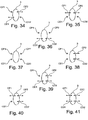
- the first to eighth possible fluidic configurations are illustrated by the Figures 34 to 41 .
- the jacket 3 is schematized by the thin mixed line, each non-fluidic communication is schematized by a cross and each fluidic communication is schematized by a two-way arrow.
- at least one of the orifices is used for admission, another for delivery.
- the first proximal duct CP1 and the second distal duct CD2 are non-conducting, that is to say that the liner 3 fluidically closes them, the first distal duct CD1 and the second proximal duct CP2 are passing through. that is to say that proximal and distal ports of the liner 3 are facing them so as to allow fluid communication with the cavity 25.
- the fluid can be admitted by the first distal duct CD1 and discharged by the second proximal duct CP2 or vice versa.
- the second proximal duct CP2 and the first distal duct CD1 are non-conducting, the first proximal duct CP1 and the second distal duct CD2 are passing.
- the fluid can be admitted via the second distal duct CD2 and delivered by the first proximal duct CP1 or vice versa.
- the first and second proximal ducts CP1, CP2 are on, and the first and second distal ducts CD1, CD2 are non-conducting. So, in the second fluidic configuration, the fluid can be admitted by the first proximal conduit CP1 and discharged by the second proximal conduit CP2 or vice versa.
- the first and second proximal conduits CP1, CP2 are on, and the first and second distal conduits CD1, CD2 are non-conducting.
- the fluid can be admitted via the first distal duct CD1 and delivered by the second distal duct CD2 or vice versa.
- the first and second proximal conduits CP1, CP2, and distal CD1, CD2 are all non-conducting.
- the fluid can not be admitted or repressed.
- the first and second proximal conduits CP1, CP2, and distal CD1, CD2 are thus isolated from the working chamber 5.
- the first proximal CP1 and distal CD1 conduits are non-conducting, the second proximal CP2 and distal CD2 conduits are passing.
- the fluid can be admitted by the second proximal conduit CP2 and delivered by the second distal conduit CD2 or vice versa.
- the first proximal conduit CP1 is non-conducting, the second proximal conduit CP2 and the first and second distal conduits CD1, CD2 are on.
- the fluid can be admitted by the first distal duct CD1 and discharged by the second proximal and distal ducts CP2, CD2 or vice versa.
- the second proximal conduit CP2 is non-passing, the first proximal conduit CP1 the first and second distal conduits CD1, CD2 are passing.
- the fluid can be admitted via the second duct distal CD2 and discharged by the first proximal and distal conduits CP1, CD1 or vice versa.
- the first and second proximal ducts CP1, CP2 and the second distal duct CD2 are on, the first distal duct CD1 is off.
- the fluid can be admitted by the first proximal conduit CP1 and discharged by the second proximal and distal conduits CP2, CD2 or vice versa.
- the first and second proximal ducts CP1, CP2 and the first distal duct CD1 are on, the second distal duct CD2 is non-conducting.
- the fluid can be admitted by the first proximal and distal conduits CP1, CD1 and delivered by the second proximal conduit CP2 or vice versa.
- the first and second proximal conduits CP1, CP2 and distal CD1, CD2 are all on.
- the fluid can be admitted by the first proximal and distal conduits CP1, CD1 and discharged by the second proximal and distal conduits CP2, CD2 or vice versa.
- the body 2 according to the first arrangement and the jacket 3 according to the first arrangement allow several fluidic configurations, three of which are illustrated and detailed below with reference to FIGS. Figures 2 to 4B .
- an arrow facing the body 2 corresponds to the inlet
- an arrow facing the opposite corresponds to the discharge.
- the inlet and the discharge can be reversed, the direction of the arrows being then also reversed.
- the jacket 3 is in the first fluid configuration (Cf. figure 34 ) in which the first proximal conduit CP1 is closed by the liner 3, the second distal orifice OP2 is opposite the second proximal conduit CP2, the first distal orifice OD1 is in view of the first distal duct CD1, the second distal duct CD2 is closed by the liner 3.
- the jacket 3 is in the second fluid configuration (Cf. figure 35 ) in which the first and the third proximal orifice OP1, OP3 are respectively opposite the first and second proximal ducts CP1, CP2, the first and the second distal ducts CD1, CD2 are closed by the jacket 3.
- the liner 3 was rotated at an angle ⁇ of 45 ° to the body counterclockwise in a distal direction of observation.
- the jacket 3 is in the third fluid configuration (Cf. figure 36 ) in which the first and the second proximal ducts CP 1, CP2 are closed by the liner 3, the second distal orifice OD2 is opposite the first distal duct CD1 and the third distal orifice OD3 is opposite the second distal duct CD2.
- the liner 3 was rotated at an angle ⁇ of 45 ° to the body counterclockwise in a distal direction of observation.
- the jacket 3 can be rotated to adopt other non-detailed fluidic configurations.
- the piston 4 is formed of two cylindrical portions 40, 41 of different diameters interconnected by a not detailed shoulder.
- the piston 4 is for example made of plastic material or any other suitable material.
- the cylindrical portion 40 of large diameter of the piston 4 has an outside diameter slightly smaller than the diameter of the cavity 25 in which it can thus be accommodated.
- the cylindrical portion 41 of small diameter of the piston 4 has an outer diameter slightly smaller than the diameter of the sleeve 3 in which it can thus be accommodated.
- the free end of the cylindrical portion 41 of small diameter defines, with the bottom of the body 2, a working chamber 5 (visible on the Figures 6 to 10 ) intended to receive the fluid.
- the free end of the cylindrical portion 40 of large diameter has an axial recess 42 visible on the figure 1 , for example in the form of a cross, adapted to receive an end-piece (not shown) of complementary shape coupled to drive means intended to rotate the piston 4 with respect to the body 2.
- the piston 4 comprises, on its periphery, a recess 43.
- the recess 43 has the shape of a groove extending longitudinally between a closed end oriented towards the cylindrical portion 40 of large diameter and one end. Opened opening in the working chamber 5.
- the recess 43 extends over a length allowing it, at each half-turn of the piston 4 in the body 2, to be successively facing the first distal and proximal ducts CD1, CP1 and second distal and proximal conduits CD2, CP2.
- the recess 43 comprises a balancing stud 44 (visible on the figure 1 ) provided at its open end and extending radially so that its top bears against the sleeve 3 while allowing the passage of the fluid on its sides.
- the piston 4 also comprises, on its periphery, a recessed area 45 (visible on the figure 1 )
- the closed area 45 and the recess 43 are delimited by a non-detailed seal, for example made of elastomer and to prevent any passage of fluid outside the recess 43 and the working chamber 5.
- the cylindrical portion 40 of large diameter of the piston 4 comprises two annular ribs 46, parallel to each other so as to define between them a double guide cam of the guide pin.
- the guide finger may also be provided with a rotating portion intended to roll on the annular ribs 46 and thus reduce friction. The energy efficiency is thus optimized.
- Guide finger and ribs annular 46 allow to transform the rotation of the piston 4 relative to the body 2 in longitudinal translation along the longitudinal axis A.
- the annular ribs 46 each comprise a first and a second inclined portion SI1, SI2, symmetrical to one another with respect to a median longitudinal plane.
- the first and second inclined portions SI1, SI2 thus have inverted slopes on the periphery of the piston 4.
- the first and second inclined portions SI1, SI2 are separated from each other by first and second planar portions SP1, SP2 substantially parallel to each other and perpendicular to the longitudinal axis A.
- the piston 4 thus oscillates between a proximal position (Cf. figure 8 ) in which the working chamber 5 has a maximum volume and a distal position (Cf. figure 5 ) in which the working chamber 5 has a minimum volume. Between these two positions of the piston 4, the working chamber 5 admits and then represses the fluid.
- a first switching phase illustrated by the figure 5 the guide finger flows along the first flat portion SP1 of the cam.
- the rotation R of the piston 4 does not then cause its translation, it remains axially immobile in its distal position, the volume of the working chamber 5 does not vary and remains minimal.
- the first distal duct CD1 and the second distal duct CD2 are opposite the solid portion of the piston 4.
- the working chamber 5 is fluidly sealed.
- the rotation R of the piston 4 relative to the body 2 is extended until reaching the intake phase.
- the guiding finger circulates mainly along the first inclined portion SI1 of the cam which converts the rotation R of the piston 4 into a proximal translation TP of the piston 4 with respect to the body 2.
- the piston 4 passes from the distal position ( figure 5 ) at a proximal position ( figure 8 ) in which the working chamber 5 has a maximum volume.
- the piston 4 rotates relative to the body 2 with the recess 43 flowing in front of the first distal duct CD1 and the first proximal duct CP1.
- the first distal duct CD1 is in fluid communication with the working chamber 5 via the second distal orifice OD2 and the recess 43.
- the fluid is sucked along the arrow E, by increasing the volume of the chamber work 5 caused by the proximal translation TP and the depression generated in the working chamber 5.
- the first proximal conduit CP1 and the second proximal conduit CP2 remain closed by the jacket 3.
- the sealing of the recessed area 45 is provided by the seal
- the second distal duct CD2 is not in fluid communication with the working chamber 5, which is schematized by a cross.
- the rotation R of the piston 4 with respect to the body 2 is extended until reaching a second switching phase.
- the guide finger flows on the end of the second flat portion SP2.
- the guide finger flows on the beginning of the first flat portion SP1 of the cam.
- the transition phases occur at constant volume of the working chamber 5.
- the second switching phase illustrated by the figure 8 is substantially similar to the first switching phase. It differs by the piston 4 in the proximal position and the working chamber 5 which has a maximum volume. During this second switching phase the guide pin flows along the second flat portion SP2 of the cam. The rotation R of the piston 4 does not then cause its translation, it remains axially immobile in its distal position, the volume of the working chamber 5 does not vary and remains maximum. During this second switching phase, the first distal duct CD1 and the second distal duct CD2 are facing the solid portion of the piston 4. Thus, even if the first and the second distal orifice OD1, OD2 are respectively facing the first and the second distal duct CD1, CD2, the working chamber 5 is fluidly sealed. The rotation R of the piston 4 relative to the body 2 is extended until reaching the discharge phase.
- the guide finger circulates mainly along the second inclined portion SI2 of the cam which converts the rotation R of the piston 4 into a distal translation TD, opposite to the proximal translation TP.
- the piston 4 passes from its proximal position ( figure 8 ) at its distal position ( figure 5 ).
- the piston 4 rotates relative to the body 2 with the recess 43 flowing in front of the second distal duct CD2 and the second proximal duct CP2.
- the second distal duct CD2 is in fluid communication with the working chamber 5 via the second distal orifice OD2 and the recess 43.
- the fluid is discharged according to the arrow S, by reducing the volume of the chamber. work 5 caused by the distal translation TD and creating an overpressure in the working chamber 5.
- the sealing of the recessed area 45 is provided by the seal, the first distal duct CD1 is not in fluid communication with the working chamber 5.
- the rotation R of the piston 4 relative to the body 2 is extended until reaching the first switching phase described above.
- the guide finger flows on the end of the first planar portion SP1.
- the guide finger moves on the beginning of the second flat portion SP2 of the cam.
- the transition phases occur at constant volume of the working chamber 5.
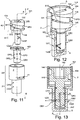
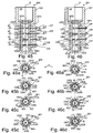
- the tilt-rotary device 101 comprises a body 2 according to the first arrangement, a liner 103 according to a second arrangement, and a piston 104 according to a second embodiment.
- the piston 104 according to the second embodiment is substantially similar to the piston 4 according to the first embodiment and differs mainly in that it comprises a distal recess 143D and a proximal recess 143P cross-shaped provided on the periphery of the cylindrical portion 41 of small diameter.
- the 143D and proximal 143P distal recesses may have any other suitable shape.
- distal recesses 143D and proximal 143P are angularly offset from one another, here by 180 °, and longitudinally from a distance depending in particular on the profile of the annular ribs 146 and provided so that, at each half-turn of the piston 104 in the body 2, the proximal recess 143P is facing one of the first and second proximal conduits CP1, CP2, and the distal recess 143D is opposite one of the first and second distal ducts CD1, CD2 .
- the piston 104 further includes a channel 147 visible on the figure 13 provided with a longitudinal section opening longitudinally in the working chamber 5, a distal radial section opening into the distal recess 143D and a proximal radial section opening into the proximal recess 143P.
- the recess axial 142 provided at the free end of the cylindrical portion 140 of large diameter has a straight slot shape.
- the liner 103 in the second arrangement is substantially similar to the liner 3 in the first arrangement. It differs in the number and location of orifices.
- the liner 103 has first, second and third proximal orifices OP1, OP2, OP3 angularly distributed in the proximal radial plane PP and first, second and third distal orifices OD1, OD2, OD3 angularly distributed in the distal radial plane DD.
- the second proximal orifice OP2 is shifted 180 ° clockwise with respect to the first proximal orifice OP1.
- the third proximal orifice OP3 is shifted 45 ° clockwise relative to the second proximal orifice OP2.
- the second distal orifice OD2 is shifted 180 ° clockwise with respect to the first distal orifice OD1.
- the third distal orifice OD3 is shifted 135 ° clockwise relative to the second distal orifice OD2.
- the first distal orifice OD1 is offset 90 ° counterclockwise with respect to the first proximal orifice OP1.
- the body 2 according to the first arrangement and the liner 103 according to the second arrangement allow several fluidic configurations, some of which are illustrated and detailed below.
- the liner 103 is in the fourth fluid configuration (Cf. figure 37 ) in which the first and second distal conduits CD1, CD2 and proximal CP1, CP2 are closed by the jacket 103.
- the jacket 103 is in the second fluid configuration (Cf. figure 35 ) in which the first and the second proximal orifice OP1, OP2 are respectively opposite the first and second proximal ducts CP1, CP2, the first and the second distal ducts CD1, CD2 are closed by the jacket 103.
- the liner 103 was rotated at an angle ⁇ of 45 ° with respect to the body 2 counterclockwise in a distal direction of observation.
- the liner 103 is in the fifth fluidic configuration (Cf. figure 38 ) in which the third proximal orifice OP3 is facing the second proximal duct CP2, the third distal orifice OD3 is opposite the second distal duct CD2, the first proximal duct CP1 and the first distal duct CD1 are closed by the liner 103.
- the liner 103 passing from the second to the fifth fluidic configuration, the liner 103 has been rotated at an angle ⁇ of 45 ° to the body counterclockwise in a distal direction of observation.
- the jacket 103 is in the third fluid configuration (Cf. figure 36 ) in which the first and second distal orifices OD1, OD2 are respectively facing second and first distal ducts CD2, CD1, the first and second proximal ducts CP1, CP2 are closed by the jacket 103.
- the liner 103 was rotated at an angle ⁇ of 45 ° relative to the body 2 in the counterclockwise direction in a distal direction of observation. Beyond this third fluid configuration, the liner 103 can be rotated to adopt other non-detailed fluidic configurations.
- such a rotary-oscillation device 101 may for example be used to reconstitute a mixture based for example on a liquid solution and a lyophilizate separately contained in two separate bottles 6, 7, and then to administer the mixture obtained to a patient or keep it in one of the vials or another container.
- the first proximal conduit CP1 is connected to a first vial 6 containing a liquid solution
- the second proximal and distal conduits CP2, CD2 are connected to a second vial 7 containing a lyophilisate
- the first distal conduit CD1 is connected to a device administration 8, for example by injection.
- These connections can be made by any suitable means, for example pipes.
- the pipes are shown in solid lines when fluid flows inside and dotted in the absence of fluid flow in the pipe.
- the liner 103 (shown in fine phantom) is retained in the fourth fluidic configuration (Cf. Figures 14, 14A, 14B and 37 ).
- the liquid solution in the first vial 6 remains, at this stage, fluidly separated from the lyophilizate stored in the second vial 7.
- the liner 103 is disposed in the second fluid configuration (Cf. Figures 15, 15A, 15B and 35 ).
- the piston 104 is actuated so as to suck the liquid solution into the working chamber 5 by the first proximal conduit CP1 and to push it from the working chamber 5 by the second proximal conduit CP2 to the second bottle 7.
- the liquid solution is thus transferred from the first vial 6 containing it initially to the second vial 7 containing the lyophilizate.
- the mixture of liquid solution and lyophilizate can be homogenized by going back and forth between the first and second bottles 6, 7 by reversing the direction of rotation of the piston 104.
- the liner 103 is disposed in the fifth fluidic configuration (Cf. Figures 16, 16A and 16B and 38 ).
- the piston 104 is actuated so as to suck up the liquid solution and the lyophilizate of the second bottle 7 in the working chamber 5 by the second distal conduit CD2 and to push it from the working chamber 5 to the second bottle 7 by the second conduit proximal CP2. Circulation and mixing of the liquid solution and lyophilizate makes it possible to obtain a homogeneous mixture in the second bottle 7.
- the liner 103 is disposed in the third fluid configuration (Cf. Figures 17, 17A and 17B and 36 ).
- the piston 104 is actuated so as to suck the mixture contained in the second vial into the working chamber 5 by the second distal duct CD2 and to discharge it from the working chamber 5 through the first distal duct CD1 to the delivery device 8.
- a part of the mixture may be preserved in the first bottle 6, another part of the mixture being contained in the second bottle 7 to be transferred to the administration device 8.
- the part of the mixture stored in the first vial 6 can then be transferred to the second vial 7 and to the delivery device 8.
- the administration can thus be sequenced in time.
- the sequencing can be decomposed into a higher number of sequences, the volume administered to each sequence being adapted as needed.
- the rotary oscillation device 101 of the Figures 11 to 17B can be used for any other application.
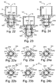
- the jacket 203 according to this third arrangement is substantially similar to the shirts 3 and 103 of the first and second arrangements. It differs in the number and location of orifices.
- the liner 203 comprises first, second, third, fourth and fifth proximal orifices OP1, OP2, OP3, OP4, OP5, angularly distributed in the proximal radial plane PP and first, second, third, fourth and fifth distal orifices OD1, OD2 , OD3, OD4, OD5 angularly distributed in the distal radial plane DD.
- the second OD2 proximal orifice is shifted 45 ° clockwise from the first proximal orifice OD1.
- the third proximal orifice OP3 is shifted 90 ° clockwise relative to the second proximal orifice OP2.
- the fourth proximal orifice OP4 is shifted 45 ° clockwise relative to the third proximal orifice OP3.
- the fifth proximal orifice OP5 is shifted 45 ° clockwise relative to the fourth proximal orifice OP4.
- the second distal orifice OD2 is shifted 90 ° clockwise from the first distal orifice OD1.
- the third distal orifice OD3 is shifted 90 ° clockwise relative to the second distal orifice OD2.
- the fourth distal orifice OD4 is shifted 45 ° clockwise relative to the third distal orifice OD3.
- the fifth distal orifice OD5 is shifted 45 ° clockwise relative to the fourth distal orifice OD4.
- the first distal orifice OD1 is offset by 45 ° counterclockwise relative to the first proximal orifice OP1.
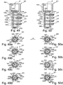
- the jacket 203 is in the sixth fluid configuration (Cf. figure 39 ) in which the first, second, fourth and fifth proximal orifices OP1, OP2, OP4, OP5 as well as the second, fourth and fifth distal orifices OD2, OD4, OD5 are closed by the jacket 203, the third proximal orifice OP3 is opposite of the second proximal conduit CP2, the first and the third distal orifice OD1, OD3 are respectively opposite first and second distal conduits CD1, CD2.
- the jacket 203 is in the seventh fluidic configuration (Cf. figure 40 ) in which the first and fourth proximal ports OP1, OP4 are respectively opposite first and second proximal conduits CP1, CP2, the first, second, third and fifth distal orifices OD1, OD2, OD3, OD5 are closed by the jacket 203 and the fourth distal orifice OD4 is opposite the second distal duct CD2.
- the jacket 203 has been rotated by an angle ⁇ of 45 ° by relative to the body 2 counterclockwise in a distal direction of observation.
- the jacket 203 is in the eighth fluidic configuration (Cf. figure 41 ) in which the first and the fifth proximal orifice OP1, OP5 are respectively opposite first and second proximal conduits CP1, CP2, the second and the fifth distal orifice OD2, OD5 are respectively opposite first and second distal ducts CD1 , CD2.
- the liner 203 was rotated at an angle ⁇ of 45 ° with respect to the body 2 counterclockwise in a distal direction of observation.
- angles separating the orifices of the jacket are different and allow additional fluidic configurations.
- the orifices are chosen, in number and location, according to the desired fluidic configurations.
- conduits provided in the body are not diametrically opposed to each other, but arranged at an angle, for example chosen according to the desired fluidic connection configuration.
- the ports of the jacket and recesses of the piston are arranged accordingly.
- the tilt-and-turn device 201 comprises a body 2 according to the first arrangement, a liner 303 according to a fourth arrangement, and a piston 204 according to a third embodiment.
- the piston 204 according to the third embodiment is substantially similar to the piston 104 according to the second embodiment. It differs mainly in that the distal recess 143D and the proximal recess 143P are aligned longitudinally with each other. As previously indicated, the conduits in the body may not be diametrically opposed to each other, but arranged at any other angle adapted, the openings of the liner and recesses of the piston being arranged accordingly.
- the piston 204 comprises a channel 247 formed of a longitudinal section, a distal radial section and a proximal radial section.
- the same jacket 303 thus makes it possible to adopt four distinct fluidic configurations without counting the first symmetrical fluidic configuration.
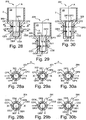
- the tilt-rotary device 201 comprises a liner 403 in a fifth arrangement.
- the sleeve 403 differs from the preceding by the number and the location of the orifices. It comprises first, second, third, fourth, fifth and sixth proximal orifices OP1, OP2, OP3, OP4, OP5, OP6 angularly distributed in the proximal radial plane PP and first, second, third and fourth distal orifices OD1, OD2, OD3, OD4 angularly distributed in the distal radial plane DD.
- first, second, third, fourth, fifth and sixth proximal orifices OP1, OP2, OP3, OP4, OP5, OP6 are mutually offset by 45 ° in the clockwise direction.
- the second distal orifice OD2 is shifted 135 ° clockwise from the first distal orifice OD1.
- the third distal orifice OD3 is shifted 135 ° clockwise relative to the second distal orifice OD2.
- the fourth distal orifice OD4 is shifted 45 ° clockwise relative to the third distal orifice OD3.
- the first distal orifice OD1 is longitudinally aligned with the first proximal orifice OP1.
- the same jacket 403 also makes it possible to adopt the first fluid configuration (Cf. figure 34 , 30, 30A and 30B ) and the second fluidic configuration (Cf. figure 36 , 29, 29A and 29B ).
- the orifices are provided in the jacket according to the combinations of configurations. desired fluidics for each specific application of the rotary-oscillation device 1, 101, 201 according to the invention.
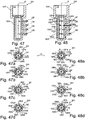
- the tilt-and-turn device 301 includes a body 102 in a second arrangement, a liner 503 in a fifth arrangement, and a piston 304 in a fourth embodiment.
- the body 102 differs from the previous ones in that the four pipes CP, CR, CS, CD are superimposed on each other, aligned longitudinally with each other, so that all the fluidic connections of the tilt-and-turn device 301 operate on the same side.
- the body 102 thus comprises a proximal conduit CP located in a proximal plane PP, a distal canal CD located in a distal plane DD and an intermediate proximal conduit CR located in an intermediate proximal plane RR and an intermediate distal conduit CS located in a intermediate distal plane SS.
- each proximal 143P and distal recess 143D has the shape of an inclined slit sufficiently extended longitudinally to cover simultaneously the proximal conduit CP and the intermediate proximal conduit CR, or the distal conduit CD and the distal intermediate conduit CS.
- the sleeve 503 according to the fifth arrangement is illustrated by the Figures 45 to 54 . It comprises six proximal orifices OP1, OP2, OP3, OP4, OP5, OP6 distributed in the proximal plane PP, six distal orifices OD1, OD2, OD3, OD4, OD5, OD6 distributed in the distal plane DD as well as six intermediate proximal orifices OR1 , OR2, OR3, OR4, OR5, OR6 distributed in the intermediate proximal plane RR and six intermediate distal ports OS1, OS2, OS3, OS4, OS5, OS6 distributed in the intermediate distal plane SS.
- the proximal, distal, proximal orifices intermediary and distal intermediates are arranged between them in longitudinal planes offset from each other by 40 °
- the second proximal orifice OP2 is shifted 80 ° clockwise from the first proximal orifice OP1.
- the third proximal orifice OP3 is shifted 40 ° clockwise relative to the second proximal orifice OP2.
- the fourth proximal orifice OP4 is shifted 80 ° clockwise from the third proximal orifice OP3.
- the fifth proximal orifice OP5 is shifted 40 ° clockwise from the fourth proximal orifice OP4.
- the sixth proximal orifice OP6 is shifted 80 ° clockwise from the fifth proximal orifice OP5.
- the second intermediate proximal orifice OR2 is shifted 40 ° clockwise from the first intermediate proximal orifice OR1.
- the third intermediate proximal orifice OR3 is shifted 40 ° clockwise relative to the second intermediate proximal orifice OR2.
- the fourth intermediate proximal orifice OR4 is shifted 40 ° clockwise relative to the third intermediate proximal orifice OR3.
- the fifth proximal proximal orifice OR5 is shifted 120 ° clockwise from the fourth proximal proximal orifice OR4.
- the sixth proximal proximal orifice OR6 is shifted 40 ° clockwise from the fifth proximal proximal orifice OR5.
- the first intermediate proximal orifice OR1 is offset by 40 ° in the clockwise direction with respect to the first proximal orifice OP1.
- the second intermediate distal orifice OS2 is shifted by 40 ° in the clockwise direction relative to the first intermediate distal orifice OS1.
- the third intermediate distal orifice OS3 is shifted by 40 ° in the clockwise direction relative to the second intermediate distal orifice OS2.
- the fourth intermediate distal orifice OS4 is shifted by 40 ° in the clockwise direction relative to the third intermediate distal orifice OS3.
- the fifth distal orifice intermediate OS5 is shifted 80 ° clockwise relative to the fourth intermediate distal orifice OS4.
- the sixth intermediate distal orifice OS6 is shifted 80 ° clockwise relative to the fifth intermediate distal orifice OS5.
- the first intermediate distal orifice OS1 is offset by 40 ° counterclockwise relative to the first intermediate proximal orifice OR1.
- second distal orifice OD2 is shifted 40 ° clockwise relative to the first distal orifice OD1.
- the third distal orifice OD3 is shifted 80 ° clockwise from the second distal orifice OD2.
- the fourth distal orifice OD4 is shifted 40 ° clockwise relative to the third distal orifice OD3.
- the fifth distal orifice OD5 is shifted 80 ° clockwise from the fourth distal orifice OD4.
- the sixth distal orifice OD6 is shifted 80 ° clockwise from the fifth distal orifice OD5.
- the first distal orifice OD1 is aligned longitudinally with the first intermediate distal orifice OS1.
- the liner 503 is in a ninth fluidic configuration in which the proximal conduit CP is closed by the liner 503, the fourth intermediate proximal orifice OR4 is opposite the intermediate proximal conduit CR which is passing, the intermediate distal duct CS is closed by the 503, the fourth distal orifice OD4 is opposite the distal duct CD which is passing.
- the fluid can be admitted via the distal duct CD and discharged through the intermediate CP proximal conduit, or vice versa.
- the liner 503 is in a tenth fluid configuration in which the fourth proximal orifice OP4 is facing the proximal conduit CP which is passing, the intermediate proximal conduit CR is closed by the liner 503, the fifth intermediate distal orifice OS5 is opposite the intermediate distal duct CS which is passing, the fourth distal orifice OD4 is closed by the jacket 503.
- the fluid can be admitted via the intermediate distal duct CS and discharged via the proximal duct CP, or vice versa.
- the liner 503 is in an eleventh fluid configuration in which the fifth proximal orifice OP5 is opposite the proximal conduit CP which is passing, the intermediate proximal conduit CR is closed by the liner 503, the intermediate distal conduit I is closed by the 503, the fifth distal orifice OD5 is opposite the fourth distal duct CD4 which is passing.
- the fluid can be admitted via the distal duct CD and delivered by the proximal duct CP, or vice versa.
- the liner 503 is in a twelfth fluid configuration in which the proximal conduit CP is closed by the liner 503, the fifth intermediate proximal orifice OR5 is opposite the intermediate proximal conduit CR which is passing, the sixth intermediate distal orifice OS6 is opposite of the intermediate distal duct CS which is passing, the distal duct CD is closed by the liner 503.
- the fluid can be admitted via the intermediate distal duct CS and discharged through the intermediate proximal duct CR, or vice versa .
- the jacket 503 is in a thirteenth fluid configuration in which the sixth proximal orifice OP6 is opposite the proximal conduit CP which is passing, the sixth intermediate proximal orifice OR6 is opposite the intermediate proximal conduit CR which is passing through, the intermediate distal conduit CS is closed by the liner 503, the sixth distal orifice OD6 is opposite the distal duct CD which is passing.
- the fluid can be admitted via the distal duct CD and discharged through the proximal intermediate CR and proximal CP conduits, or vice versa.
- the 503 shirt is in a fourteenth fluidic configuration in which the first proximal orifice OP1 is facing the proximal conduit CP which is passing, the intermediate proximal conduit CR is closed by the sleeve 503, the first intermediate distal orifice OS1 is opposite the intermediate distal conduit CS which is passing, the first distal orifice OD1 is opposite the distal duct CD which is passing.
- the fluid can be admitted via the distal CD and distal intermediate conduits CS and delivered by the proximal conduit CP, or vice versa.
- the liner 503 is in a fifteenth fluidic configuration in which the proximal conduit CP is closed by the liner 503, the first intermediate proximal orifice OR1 is opposite the intermediate proximal conduit CR which is passing, the second intermediate distal orifice OS2 is opposite of the intermediate distal duct CS which is passing, the second distal orifice OD2 is opposite the distal duct CD which is passing.
- the fluid can be admitted via the distal CD and distal intermediate CS conduits and discharged through the intermediate proximal conduit CR, or vice versa.
- the liner 503 is in a sixteenth fluid configuration in which the second proximal orifice OP2 is facing the proximal conduit CP which is passing, the second intermediate proximal orifice OR2 is opposite the intermediate proximal conduit CR which is passing, the third distal orifice intermediate OS3 is opposite the intermediate distal duct CS which is passing, the distal duct CD is closed by the liner 503.
- the fluid can be admitted via the intermediate distal duct CS and discharged by the proximal ducts intermediate CR and proximal CP, or vice versa.
- the liner 503 is in a seventeenth fluid configuration in which the third proximal orifice OP3 is opposite the proximal duct CP which is passing, the third intermediate proximal orifice OR3 is facing the intermediate proximal conduit CR which is passing, the fourth intermediate distal orifice OS4 is opposite the intermediate distal conduit CS which is passing, the third distal orifice OD3 is opposite the distal conduit CD who is passing.
- all the ducts are conducting and the fluid can be admitted via the distal CD and distal intermediate ducts CS and discharged through the proximal intermediate CR and proximal CP conduits, or vice versa.
- the liner 503 has been rotated by an angle ⁇ of 40 ° to the body 102 counterclockwise in a distal direction of observation.
- the same jacket 503 thus allows nine distinct fluidic configurations. This number can of course be lower.
- the oscillating-rotary subassembly according to the invention may of course comprise additional conduits and additional orifices respectively provided in the body and the jacket, these conduits and additional orifices being provided in radial planes intermediate to the radial planes previously described.
- the oscillation-rotary pumping device comprises an oscillating-rotary subassembly 1, 101, 201, 301 as previously described, the piston of which is mechanically coupled to known-type drive means.
- This mechanical coupling can be achieved by means of removable mechanical coupling means making it possible to be easily decoupled from the piston 4; 104; 204; 304.
- the drive means can form a reusable subassembly while the oscillating-rotational subassembly 1, 101, 201, 301 forms a disposable subassembly.
- Moving the shirt 3; 103; 203; 303; 403; 503 between the different fluidic configurations can be obtained manually or motorized by any known means cooperating with the training forms provided on the shirt 3; 103; 203; 303; 403; 503.
- the fluidic communication between the ducts and the working chamber 5 is obtained via the The invention thus makes it possible to achieve the above-mentioned objectives by increasing, for a predetermined number of ducts, the number of possible fluidic configurations while maintaining simplicity, compactness, and stability. a reduced number of pieces.
- the tilt-rotary device 1, 101, 201, 301 allows different fluidic connections allowing applications various without changing neither the body 2, 102 nor the piston 4, 104, 204, 304 nor the sleeve 3, 103, 203, 303, 403, 503 of the tilt-rotary device 1, 101, 201, 301.
- the liner is angularly movable relative to the body.
- the liner may be provided so as to be able to slide longitudinally with respect to the body, the change from one fluidic configuration to another then acting by translating the chamber into the body.
- the orifices used from one fluidic configuration to another will be aligned with each other longitudinally, the spacing between the orifices varying according to the fluidic communications to ensure or not.
- Translation and rotation of the liner relative to the body can also be combined.
- the shirt can be provided without bottom, in the form of a sheath open at both ends. Several options are then possible.
- the longitudinal wall of the liner may extend to the bottom of the body.
- Wall Longitudinal can also be interrupted under the distal duct, the body may then include an inner diameter of reduced section limiting the dead volume around the piston when the latter is in its distal position.
- the working chamber is at least partially defined directly by the body wall.
- the body comprises at least two proximal and two distal ducts. It is understood that multiplexing is possible with a body having two proximal ducts and a single distal duct, or a single proximal duct and two distal ducts.
- the illustrated examples relate to a single-stage single-stage oscillo-rotary subassembly.
- the oscillating-rotational subassembly can also have a multi-effect configuration. For this purpose, in a commonly accepted manner, it will comprise several stages.
Landscapes
- Engineering & Computer Science (AREA)
- General Engineering & Computer Science (AREA)
- Mechanical Engineering (AREA)
- Infusion, Injection, And Reservoir Apparatuses (AREA)
- Media Introduction/Drainage Providing Device (AREA)
- Reciprocating Pumps (AREA)
Applications Claiming Priority (2)
| Application Number | Priority Date | Filing Date | Title |
|---|---|---|---|
| FR1357188A FR3008745B1 (fr) | 2013-07-22 | 2013-07-22 | Sous-ensemble oscillo-rotatif et dispositif pour multiplexage fluidique et pompage volumetrique co-integres d'un fluide |
| PCT/FR2014/051416 WO2015011353A1 (fr) | 2013-07-22 | 2014-06-11 | Sous-ensemble oscillo-rotatif et dispositif pour multiplexage fluidique et pompage volumétrique co-intégrés d'un fluide |
Publications (2)
| Publication Number | Publication Date |
|---|---|
| EP3025057A1 EP3025057A1 (fr) | 2016-06-01 |
| EP3025057B1 true EP3025057B1 (fr) | 2017-05-17 |
Family
ID=50064704
Family Applications (1)
| Application Number | Title | Priority Date | Filing Date |
|---|---|---|---|
| EP14738555.3A Not-in-force EP3025057B1 (fr) | 2013-07-22 | 2014-06-11 | Sous-ensemble oscillo-rotatif et dispositif pour multiplexage fluidique et pompage volumétrique co-intégrés d'un fluide |
Country Status (11)
| Country | Link |
|---|---|
| US (1) | US10393096B2 (enExample) |
| EP (1) | EP3025057B1 (enExample) |
| JP (1) | JP2016525645A (enExample) |
| KR (1) | KR20160045711A (enExample) |
| CN (1) | CN105556119B (enExample) |
| AU (1) | AU2014294902B2 (enExample) |
| CA (1) | CA2918995C (enExample) |
| ES (1) | ES2629412T3 (enExample) |
| FR (1) | FR3008745B1 (enExample) |
| WO (1) | WO2015011353A1 (enExample) |
| ZA (1) | ZA201600455B (enExample) |
Families Citing this family (10)
| Publication number | Priority date | Publication date | Assignee | Title |
|---|---|---|---|---|
| CN105110231B (zh) * | 2015-09-17 | 2017-08-29 | 京东方科技集团股份有限公司 | 一种液压千斤顶 |
| US10363912B2 (en) * | 2017-03-09 | 2019-07-30 | Ford Global Technologies, Llc | Hydraulic brake actuators and related methods |
| WO2019084084A2 (en) * | 2017-10-24 | 2019-05-02 | Dow Global Technologies Llc | PULSED COMPRESSION REACTORS AND METHODS OF OPERATION THEREOF |
| EP3499034B1 (en) * | 2017-12-12 | 2021-06-23 | Sensile Medical AG | Micropump with cam mechanism for axial displacement of rotor |
| US11174852B2 (en) | 2018-07-20 | 2021-11-16 | Becton, Dickinson And Company | Reciprocating pump |
| EP3657055A1 (en) * | 2018-11-22 | 2020-05-27 | Rosemount Aerospace, Inc. | Fluid valve |
| CN114450046B (zh) * | 2019-08-26 | 2023-12-08 | 伊莱利利公司 | 旋转柱塞泵子系统 |
| DK4135830T3 (da) | 2020-12-23 | 2024-10-28 | Tolmar International Ltd | Systemer og fremgangsmåder til blanding af sprøjteventilanordninger |
| CN114649917B (zh) * | 2022-05-19 | 2022-08-05 | 浙大城市学院 | 一种二维电机组合活塞泵 |
| USD1029245S1 (en) | 2022-06-22 | 2024-05-28 | Tolmar International Limited | Syringe connector |
Family Cites Families (15)
| Publication number | Priority date | Publication date | Assignee | Title |
|---|---|---|---|---|
| US2927570A (en) * | 1958-02-03 | 1960-03-08 | Gen Motors Corp | Fuel injection system |
| US3168872A (en) | 1963-01-23 | 1965-02-09 | Harry E Pinkerton | Positive displacement piston pump |
| US3486455A (en) * | 1968-05-09 | 1969-12-30 | Minijector Corp | Variable stroke plunger pump |
| US3893481A (en) * | 1973-03-13 | 1975-07-08 | Watts Ltd H & D | Mixer taps or valves |
| DE3441215A1 (de) * | 1984-11-10 | 1986-05-15 | Alfred Teves Gmbh, 6000 Frankfurt | Hydraulische pumpe |
| DE3630528A1 (de) * | 1986-09-08 | 1988-03-10 | Klaus Hirsch | Kolbenpumpe |
| US4971099A (en) * | 1989-12-15 | 1990-11-20 | Cooper Industries, Inc. | Pressure balanced cartridge choke valve |
| FI94164C (fi) * | 1991-03-21 | 1995-07-25 | Borealis Polymers Oy | Menetelmä juoksevaksi saatetun polymerointikatalyytin annostelemiseksi polymerointireaktoriin |
| US5312233A (en) * | 1992-02-25 | 1994-05-17 | Ivek Corporation | Linear liquid dispensing pump for dispensing liquid in nanoliter volumes |
| DE4409994A1 (de) * | 1994-03-23 | 1995-09-28 | Prominent Dosiertechnik Gmbh | Verdrängerkolbenpumpe |
| US5494420A (en) * | 1994-05-31 | 1996-02-27 | Diba Industries, Inc. | Rotary and reciprocating pump with self-aligning connection |
| JP4773595B2 (ja) * | 1999-10-18 | 2011-09-14 | 東メンシステム株式会社 | 塗装装置 |
| ES2359159T3 (es) * | 2004-11-29 | 2011-05-18 | Nomet Management Services B.V. | Bomba volumétrica con distribución continua de flujo. |
| EP2222957B1 (en) * | 2007-12-10 | 2017-01-25 | Bayer Healthcare LLC | Continuous fluid delivery system and method |
| WO2011114285A2 (en) * | 2010-03-17 | 2011-09-22 | Sensile Pat Ag | Micropump |
-
2013
- 2013-07-22 FR FR1357188A patent/FR3008745B1/fr active Active
-
2014
- 2014-06-11 WO PCT/FR2014/051416 patent/WO2015011353A1/fr not_active Ceased
- 2014-06-11 CN CN201480051186.1A patent/CN105556119B/zh not_active Expired - Fee Related
- 2014-06-11 AU AU2014294902A patent/AU2014294902B2/en not_active Ceased
- 2014-06-11 CA CA2918995A patent/CA2918995C/fr not_active Expired - Fee Related
- 2014-06-11 JP JP2016528566A patent/JP2016525645A/ja active Pending
- 2014-06-11 EP EP14738555.3A patent/EP3025057B1/fr not_active Not-in-force
- 2014-06-11 KR KR1020167004525A patent/KR20160045711A/ko not_active Abandoned
- 2014-06-11 US US14/906,368 patent/US10393096B2/en not_active Expired - Fee Related
- 2014-06-11 ES ES14738555.3T patent/ES2629412T3/es active Active
-
2016
- 2016-01-20 ZA ZA2016/00455A patent/ZA201600455B/en unknown
Non-Patent Citations (1)
| Title |
|---|
| None * |
Also Published As
| Publication number | Publication date |
|---|---|
| AU2014294902A1 (en) | 2016-02-11 |
| FR3008745A1 (fr) | 2015-01-23 |
| CA2918995C (fr) | 2017-11-07 |
| CN105556119B (zh) | 2017-07-07 |
| US20160195074A1 (en) | 2016-07-07 |
| EP3025057A1 (fr) | 2016-06-01 |
| CA2918995A1 (fr) | 2015-01-29 |
| CN105556119A (zh) | 2016-05-04 |
| US10393096B2 (en) | 2019-08-27 |
| KR20160045711A (ko) | 2016-04-27 |
| WO2015011353A1 (fr) | 2015-01-29 |
| FR3008745B1 (fr) | 2015-07-31 |
| JP2016525645A (ja) | 2016-08-25 |
| ZA201600455B (en) | 2017-03-29 |
| ES2629412T3 (es) | 2017-08-09 |
| AU2014294902B2 (en) | 2017-06-15 |
Similar Documents
| Publication | Publication Date | Title |
|---|---|---|
| EP3025057B1 (fr) | Sous-ensemble oscillo-rotatif et dispositif pour multiplexage fluidique et pompage volumétrique co-intégrés d'un fluide | |
| CA2876056C (fr) | Distributeur fluidique et dispositif de reconstitution in situ et d'administration | |
| CA2919004C (fr) | Sous-ensemble oscillo-rotatif et dispositif de pompage volumetrique oscillo-rotatif pour pompage volumetrique d'un fluide | |
| EP3121070B1 (fr) | Dispositif de nettoyage d'un capteur pour vehicule automobile | |
| CA2918927C (fr) | Sous-ensemble oscillo-rotatif pour pompage d'un fluide et dispositif de pompage oscillo-rotatif | |
| EP3094415B1 (fr) | Procede d'utilisation d'un ensemble de distribution de produit fluide | |
| WO1998001174A1 (fr) | Seringue a chambre double permettant le melange de deux produits avant leur injection | |
| CH629395A5 (fr) | Dispositif d'ejection a buse reglable pour atomiseur de liquide. | |
| WO2002045866A1 (fr) | Dispositif de distribution de produit fluide ou pulverulent | |
| WO2019170608A1 (fr) | Distributeur portatif à plusieurs pompes et à tête de distribution rotative | |
| EP3485165B1 (fr) | Mecanisme de dosage d'une pompe a dosage proportionnel, pompe et procede de mise en oeuvre associes | |
| EP2852760B1 (fr) | Pompe rotative volumétrique sans pulsation | |
| EP4100650A1 (fr) | Dispositif de distribution de liquide oscillo-rotatif avec ressort et sa méthode | |
| EP3449222A1 (fr) | Dispositif de distribution de produit liquide ou pateux | |
| EP0604888B1 (fr) | Pompe pour matière visqueuse, comportant un organe de distribution rotatif | |
| EP3297753A1 (fr) | Système de mélange d'un produit chimique avec de l'eau | |
| FR2544890A1 (fr) | Dispositif mesureur-doseur pour fluides | |
| EP1446324B1 (fr) | Systeme d'injection d'au moins deux produits dans des recipients | |
| WO2004027352A2 (fr) | Dispositif de dosage volumetrique differentiel | |
| FR3036508A1 (fr) | Dispositif de regulation de debit et systeme de melange comprenant un tel dispositif |
Legal Events
| Date | Code | Title | Description |
|---|---|---|---|
| PUAI | Public reference made under article 153(3) epc to a published international application that has entered the european phase |
Free format text: ORIGINAL CODE: 0009012 |
|
| 17P | Request for examination filed |
Effective date: 20160222 |
|
| AK | Designated contracting states |
Kind code of ref document: A1 Designated state(s): AL AT BE BG CH CY CZ DE DK EE ES FI FR GB GR HR HU IE IS IT LI LT LU LV MC MK MT NL NO PL PT RO RS SE SI SK SM TR |
|
| AX | Request for extension of the european patent |
Extension state: BA ME |
|
| DAX | Request for extension of the european patent (deleted) | ||
| GRAP | Despatch of communication of intention to grant a patent |
Free format text: ORIGINAL CODE: EPIDOSNIGR1 |
|
| STAA | Information on the status of an ep patent application or granted ep patent |
Free format text: STATUS: GRANT OF PATENT IS INTENDED |
|
| INTG | Intention to grant announced |
Effective date: 20161123 |
|
| GRAJ | Information related to disapproval of communication of intention to grant by the applicant or resumption of examination proceedings by the epo deleted |
Free format text: ORIGINAL CODE: EPIDOSDIGR1 |
|
| STAA | Information on the status of an ep patent application or granted ep patent |
Free format text: STATUS: REQUEST FOR EXAMINATION WAS MADE |
|
| GRAP | Despatch of communication of intention to grant a patent |
Free format text: ORIGINAL CODE: EPIDOSNIGR1 |
|
| STAA | Information on the status of an ep patent application or granted ep patent |
Free format text: STATUS: GRANT OF PATENT IS INTENDED |
|
| INTC | Intention to grant announced (deleted) | ||
| GRAS | Grant fee paid |
Free format text: ORIGINAL CODE: EPIDOSNIGR3 |
|
| GRAA | (expected) grant |
Free format text: ORIGINAL CODE: 0009210 |
|
| STAA | Information on the status of an ep patent application or granted ep patent |
Free format text: STATUS: THE PATENT HAS BEEN GRANTED |
|
| INTG | Intention to grant announced |
Effective date: 20170321 |
|
| AK | Designated contracting states |
Kind code of ref document: B1 Designated state(s): AL AT BE BG CH CY CZ DE DK EE ES FI FR GB GR HR HU IE IS IT LI LT LU LV MC MK MT NL NO PL PT RO RS SE SI SK SM TR |
|
| REG | Reference to a national code |
Ref country code: GB Ref legal event code: FG4D Free format text: NOT ENGLISH |
|
| REG | Reference to a national code |
Ref country code: CH Ref legal event code: EP |
|
| REG | Reference to a national code |
Ref country code: IE Ref legal event code: FG4D Free format text: LANGUAGE OF EP DOCUMENT: FRENCH |
|
| REG | Reference to a national code |
Ref country code: AT Ref legal event code: REF Ref document number: 894716 Country of ref document: AT Kind code of ref document: T Effective date: 20170615 |
|
| REG | Reference to a national code |
Ref country code: FR Ref legal event code: PLFP Year of fee payment: 4 |
|
| REG | Reference to a national code |
Ref country code: DE Ref legal event code: R096 Ref document number: 602014009968 Country of ref document: DE |
|
| REG | Reference to a national code |
Ref country code: NL Ref legal event code: FP |
|
| REG | Reference to a national code |
Ref country code: ES Ref legal event code: FG2A Ref document number: 2629412 Country of ref document: ES Kind code of ref document: T3 Effective date: 20170809 |
|
| REG | Reference to a national code |
Ref country code: LT Ref legal event code: MG4D |
|
| REG | Reference to a national code |
Ref country code: AT Ref legal event code: MK05 Ref document number: 894716 Country of ref document: AT Kind code of ref document: T Effective date: 20170517 |
|
| PG25 | Lapsed in a contracting state [announced via postgrant information from national office to epo] |
Ref country code: LT Free format text: LAPSE BECAUSE OF FAILURE TO SUBMIT A TRANSLATION OF THE DESCRIPTION OR TO PAY THE FEE WITHIN THE PRESCRIBED TIME-LIMIT Effective date: 20170517 Ref country code: GR Free format text: LAPSE BECAUSE OF FAILURE TO SUBMIT A TRANSLATION OF THE DESCRIPTION OR TO PAY THE FEE WITHIN THE PRESCRIBED TIME-LIMIT Effective date: 20170818 Ref country code: FI Free format text: LAPSE BECAUSE OF FAILURE TO SUBMIT A TRANSLATION OF THE DESCRIPTION OR TO PAY THE FEE WITHIN THE PRESCRIBED TIME-LIMIT Effective date: 20170517 Ref country code: HR Free format text: LAPSE BECAUSE OF FAILURE TO SUBMIT A TRANSLATION OF THE DESCRIPTION OR TO PAY THE FEE WITHIN THE PRESCRIBED TIME-LIMIT Effective date: 20170517 Ref country code: AT Free format text: LAPSE BECAUSE OF FAILURE TO SUBMIT A TRANSLATION OF THE DESCRIPTION OR TO PAY THE FEE WITHIN THE PRESCRIBED TIME-LIMIT Effective date: 20170517 Ref country code: NO Free format text: LAPSE BECAUSE OF FAILURE TO SUBMIT A TRANSLATION OF THE DESCRIPTION OR TO PAY THE FEE WITHIN THE PRESCRIBED TIME-LIMIT Effective date: 20170817 |
|
| PG25 | Lapsed in a contracting state [announced via postgrant information from national office to epo] |
Ref country code: RS Free format text: LAPSE BECAUSE OF FAILURE TO SUBMIT A TRANSLATION OF THE DESCRIPTION OR TO PAY THE FEE WITHIN THE PRESCRIBED TIME-LIMIT Effective date: 20170517 Ref country code: IS Free format text: LAPSE BECAUSE OF FAILURE TO SUBMIT A TRANSLATION OF THE DESCRIPTION OR TO PAY THE FEE WITHIN THE PRESCRIBED TIME-LIMIT Effective date: 20170917 Ref country code: LV Free format text: LAPSE BECAUSE OF FAILURE TO SUBMIT A TRANSLATION OF THE DESCRIPTION OR TO PAY THE FEE WITHIN THE PRESCRIBED TIME-LIMIT Effective date: 20170517 Ref country code: BG Free format text: LAPSE BECAUSE OF FAILURE TO SUBMIT A TRANSLATION OF THE DESCRIPTION OR TO PAY THE FEE WITHIN THE PRESCRIBED TIME-LIMIT Effective date: 20170817 Ref country code: SE Free format text: LAPSE BECAUSE OF FAILURE TO SUBMIT A TRANSLATION OF THE DESCRIPTION OR TO PAY THE FEE WITHIN THE PRESCRIBED TIME-LIMIT Effective date: 20170517 Ref country code: PL Free format text: LAPSE BECAUSE OF FAILURE TO SUBMIT A TRANSLATION OF THE DESCRIPTION OR TO PAY THE FEE WITHIN THE PRESCRIBED TIME-LIMIT Effective date: 20170517 |
|
| PG25 | Lapsed in a contracting state [announced via postgrant information from national office to epo] |
Ref country code: CZ Free format text: LAPSE BECAUSE OF FAILURE TO SUBMIT A TRANSLATION OF THE DESCRIPTION OR TO PAY THE FEE WITHIN THE PRESCRIBED TIME-LIMIT Effective date: 20170517 Ref country code: RO Free format text: LAPSE BECAUSE OF FAILURE TO SUBMIT A TRANSLATION OF THE DESCRIPTION OR TO PAY THE FEE WITHIN THE PRESCRIBED TIME-LIMIT Effective date: 20170517 Ref country code: SK Free format text: LAPSE BECAUSE OF FAILURE TO SUBMIT A TRANSLATION OF THE DESCRIPTION OR TO PAY THE FEE WITHIN THE PRESCRIBED TIME-LIMIT Effective date: 20170517 Ref country code: EE Free format text: LAPSE BECAUSE OF FAILURE TO SUBMIT A TRANSLATION OF THE DESCRIPTION OR TO PAY THE FEE WITHIN THE PRESCRIBED TIME-LIMIT Effective date: 20170517 Ref country code: DK Free format text: LAPSE BECAUSE OF FAILURE TO SUBMIT A TRANSLATION OF THE DESCRIPTION OR TO PAY THE FEE WITHIN THE PRESCRIBED TIME-LIMIT Effective date: 20170517 |
|
| REG | Reference to a national code |
Ref country code: CH Ref legal event code: PL |
|
| REG | Reference to a national code |
Ref country code: DE Ref legal event code: R097 Ref document number: 602014009968 Country of ref document: DE |
|
| PG25 | Lapsed in a contracting state [announced via postgrant information from national office to epo] |
Ref country code: SM Free format text: LAPSE BECAUSE OF FAILURE TO SUBMIT A TRANSLATION OF THE DESCRIPTION OR TO PAY THE FEE WITHIN THE PRESCRIBED TIME-LIMIT Effective date: 20170517 |
|
| REG | Reference to a national code |
Ref country code: IE Ref legal event code: MM4A |
|
| PLBE | No opposition filed within time limit |
Free format text: ORIGINAL CODE: 0009261 |
|
| STAA | Information on the status of an ep patent application or granted ep patent |
Free format text: STATUS: NO OPPOSITION FILED WITHIN TIME LIMIT |
|
| 26N | No opposition filed |
Effective date: 20180220 |
|
| PG25 | Lapsed in a contracting state [announced via postgrant information from national office to epo] |
Ref country code: LU Free format text: LAPSE BECAUSE OF NON-PAYMENT OF DUE FEES Effective date: 20170611 Ref country code: IE Free format text: LAPSE BECAUSE OF NON-PAYMENT OF DUE FEES Effective date: 20170611 Ref country code: CH Free format text: LAPSE BECAUSE OF NON-PAYMENT OF DUE FEES Effective date: 20170630 Ref country code: LI Free format text: LAPSE BECAUSE OF NON-PAYMENT OF DUE FEES Effective date: 20170630 |
|
| PG25 | Lapsed in a contracting state [announced via postgrant information from national office to epo] |
Ref country code: SI Free format text: LAPSE BECAUSE OF FAILURE TO SUBMIT A TRANSLATION OF THE DESCRIPTION OR TO PAY THE FEE WITHIN THE PRESCRIBED TIME-LIMIT Effective date: 20170517 |
|
| REG | Reference to a national code |
Ref country code: FR Ref legal event code: PLFP Year of fee payment: 5 |
|
| PGFP | Annual fee paid to national office [announced via postgrant information from national office to epo] |
Ref country code: NL Payment date: 20180620 Year of fee payment: 5 |
|
| PGFP | Annual fee paid to national office [announced via postgrant information from national office to epo] |
Ref country code: TR Payment date: 20180625 Year of fee payment: 8 Ref country code: BE Payment date: 20180620 Year of fee payment: 5 |
|
| PG25 | Lapsed in a contracting state [announced via postgrant information from national office to epo] |
Ref country code: MT Free format text: LAPSE BECAUSE OF FAILURE TO SUBMIT A TRANSLATION OF THE DESCRIPTION OR TO PAY THE FEE WITHIN THE PRESCRIBED TIME-LIMIT Effective date: 20170517 |
|
| PG25 | Lapsed in a contracting state [announced via postgrant information from national office to epo] |
Ref country code: HU Free format text: LAPSE BECAUSE OF FAILURE TO SUBMIT A TRANSLATION OF THE DESCRIPTION OR TO PAY THE FEE WITHIN THE PRESCRIBED TIME-LIMIT; INVALID AB INITIO Effective date: 20140611 Ref country code: MC Free format text: LAPSE BECAUSE OF FAILURE TO SUBMIT A TRANSLATION OF THE DESCRIPTION OR TO PAY THE FEE WITHIN THE PRESCRIBED TIME-LIMIT Effective date: 20170517 |
|
| PG25 | Lapsed in a contracting state [announced via postgrant information from national office to epo] |
Ref country code: CY Free format text: LAPSE BECAUSE OF FAILURE TO SUBMIT A TRANSLATION OF THE DESCRIPTION OR TO PAY THE FEE WITHIN THE PRESCRIBED TIME-LIMIT Effective date: 20170517 |
|
| PG25 | Lapsed in a contracting state [announced via postgrant information from national office to epo] |
Ref country code: MK Free format text: LAPSE BECAUSE OF FAILURE TO SUBMIT A TRANSLATION OF THE DESCRIPTION OR TO PAY THE FEE WITHIN THE PRESCRIBED TIME-LIMIT Effective date: 20170517 |
|
| REG | Reference to a national code |
Ref country code: NL Ref legal event code: MM Effective date: 20190701 |
|
| REG | Reference to a national code |
Ref country code: BE Ref legal event code: MM Effective date: 20190630 |
|
| PG25 | Lapsed in a contracting state [announced via postgrant information from national office to epo] |
Ref country code: NL Free format text: LAPSE BECAUSE OF NON-PAYMENT OF DUE FEES Effective date: 20190701 |
|
| PG25 | Lapsed in a contracting state [announced via postgrant information from national office to epo] |
Ref country code: PT Free format text: LAPSE BECAUSE OF FAILURE TO SUBMIT A TRANSLATION OF THE DESCRIPTION OR TO PAY THE FEE WITHIN THE PRESCRIBED TIME-LIMIT Effective date: 20170517 Ref country code: BE Free format text: LAPSE BECAUSE OF NON-PAYMENT OF DUE FEES Effective date: 20190630 |
|
| PG25 | Lapsed in a contracting state [announced via postgrant information from national office to epo] |
Ref country code: AL Free format text: LAPSE BECAUSE OF FAILURE TO SUBMIT A TRANSLATION OF THE DESCRIPTION OR TO PAY THE FEE WITHIN THE PRESCRIBED TIME-LIMIT Effective date: 20170517 |
|
| PGFP | Annual fee paid to national office [announced via postgrant information from national office to epo] |
Ref country code: IT Payment date: 20210625 Year of fee payment: 8 |
|
| PGFP | Annual fee paid to national office [announced via postgrant information from national office to epo] |
Ref country code: ES Payment date: 20210826 Year of fee payment: 8 |
|
| PG25 | Lapsed in a contracting state [announced via postgrant information from national office to epo] |
Ref country code: TR Free format text: LAPSE BECAUSE OF NON-PAYMENT OF DUE FEES Effective date: 20190611 |
|
| PG25 | Lapsed in a contracting state [announced via postgrant information from national office to epo] |
Ref country code: IT Free format text: LAPSE BECAUSE OF NON-PAYMENT OF DUE FEES Effective date: 20220611 |
|
| PGFP | Annual fee paid to national office [announced via postgrant information from national office to epo] |
Ref country code: FR Payment date: 20230628 Year of fee payment: 10 Ref country code: DE Payment date: 20230620 Year of fee payment: 10 |
|
| REG | Reference to a national code |
Ref country code: ES Ref legal event code: FD2A Effective date: 20230801 |
|
| PG25 | Lapsed in a contracting state [announced via postgrant information from national office to epo] |
Ref country code: ES Free format text: LAPSE BECAUSE OF NON-PAYMENT OF DUE FEES Effective date: 20220612 |
|
| PGFP | Annual fee paid to national office [announced via postgrant information from national office to epo] |
Ref country code: GB Payment date: 20230622 Year of fee payment: 10 |
|
| REG | Reference to a national code |
Ref country code: DE Ref legal event code: R119 Ref document number: 602014009968 Country of ref document: DE |
|
| GBPC | Gb: european patent ceased through non-payment of renewal fee |
Effective date: 20240611 |
|
| PG25 | Lapsed in a contracting state [announced via postgrant information from national office to epo] |
Ref country code: DE Free format text: LAPSE BECAUSE OF NON-PAYMENT OF DUE FEES Effective date: 20250101 |
|
| PG25 | Lapsed in a contracting state [announced via postgrant information from national office to epo] |
Ref country code: FR Free format text: LAPSE BECAUSE OF NON-PAYMENT OF DUE FEES Effective date: 20240630 |
|
| PG25 | Lapsed in a contracting state [announced via postgrant information from national office to epo] |
Ref country code: GB Free format text: LAPSE BECAUSE OF NON-PAYMENT OF DUE FEES Effective date: 20240611 |